EP1950997B1 - Ultrasonic probe - Google Patents
Ultrasonic probe Download PDFInfo
- Publication number
- EP1950997B1 EP1950997B1 EP06782183.5A EP06782183A EP1950997B1 EP 1950997 B1 EP1950997 B1 EP 1950997B1 EP 06782183 A EP06782183 A EP 06782183A EP 1950997 B1 EP1950997 B1 EP 1950997B1
- Authority
- EP
- European Patent Office
- Prior art keywords
- diaphragm
- ultrasonic
- ultrasonic transducer
- beams
- diaphragms
- Prior art date
- Legal status (The legal status is an assumption and is not a legal conclusion. Google has not performed a legal analysis and makes no representation as to the accuracy of the status listed.)
- Active
Links
- 239000000523 sample Substances 0.000 title claims description 46
- 238000002604 ultrasonography Methods 0.000 claims description 41
- 239000000758 substrate Substances 0.000 claims description 33
- 230000001902 propagating effect Effects 0.000 claims description 2
- 239000000463 material Substances 0.000 description 31
- 230000005540 biological transmission Effects 0.000 description 30
- 238000010586 diagram Methods 0.000 description 29
- 230000010355 oscillation Effects 0.000 description 24
- 238000001228 spectrum Methods 0.000 description 24
- 230000000052 comparative effect Effects 0.000 description 23
- 238000003384 imaging method Methods 0.000 description 20
- 238000004519 manufacturing process Methods 0.000 description 17
- 230000000694 effects Effects 0.000 description 16
- 230000035945 sensitivity Effects 0.000 description 16
- 238000006243 chemical reaction Methods 0.000 description 15
- 239000010408 film Substances 0.000 description 13
- 239000007787 solid Substances 0.000 description 13
- 239000004065 semiconductor Substances 0.000 description 11
- 238000004364 calculation method Methods 0.000 description 10
- 238000000034 method Methods 0.000 description 10
- 230000008859 change Effects 0.000 description 9
- 230000004044 response Effects 0.000 description 9
- 229910052581 Si3N4 Inorganic materials 0.000 description 8
- 239000003990 capacitor Substances 0.000 description 8
- HQVNEWCFYHHQES-UHFFFAOYSA-N silicon nitride Chemical compound N12[Si]34N5[Si]62N3[Si]51N64 HQVNEWCFYHHQES-UHFFFAOYSA-N 0.000 description 8
- 210000004204 blood vessel Anatomy 0.000 description 7
- 229910052710 silicon Inorganic materials 0.000 description 6
- 239000010703 silicon Substances 0.000 description 6
- XUIMIQQOPSSXEZ-UHFFFAOYSA-N Silicon Chemical compound [Si] XUIMIQQOPSSXEZ-UHFFFAOYSA-N 0.000 description 5
- 238000005516 engineering process Methods 0.000 description 5
- 238000009413 insulation Methods 0.000 description 5
- 239000011295 pitch Substances 0.000 description 5
- XLYOFNOQVPJJNP-UHFFFAOYSA-N water Substances O XLYOFNOQVPJJNP-UHFFFAOYSA-N 0.000 description 5
- 238000003491 array Methods 0.000 description 4
- 230000008901 benefit Effects 0.000 description 4
- 238000006073 displacement reaction Methods 0.000 description 4
- 238000004088 simulation Methods 0.000 description 4
- 230000001154 acute effect Effects 0.000 description 3
- 229910052782 aluminium Inorganic materials 0.000 description 3
- XAGFODPZIPBFFR-UHFFFAOYSA-N aluminium Chemical compound [Al] XAGFODPZIPBFFR-UHFFFAOYSA-N 0.000 description 3
- 239000004020 conductor Substances 0.000 description 3
- 238000013461 design Methods 0.000 description 3
- 230000006866 deterioration Effects 0.000 description 3
- 229910052751 metal Inorganic materials 0.000 description 3
- 239000002184 metal Substances 0.000 description 3
- 238000012856 packing Methods 0.000 description 3
- 230000008569 process Effects 0.000 description 3
- 239000010409 thin film Substances 0.000 description 3
- -1 aluminum alloys Chemical class 0.000 description 2
- 238000005452 bending Methods 0.000 description 2
- 239000000919 ceramic Substances 0.000 description 2
- 230000007423 decrease Effects 0.000 description 2
- 238000009826 distribution Methods 0.000 description 2
- 239000011521 glass Substances 0.000 description 2
- HFGPZNIAWCZYJU-UHFFFAOYSA-N lead zirconate titanate Chemical compound [O-2].[O-2].[O-2].[O-2].[O-2].[Ti+4].[Zr+4].[Pb+2] HFGPZNIAWCZYJU-UHFFFAOYSA-N 0.000 description 2
- 229910052451 lead zirconate titanate Inorganic materials 0.000 description 2
- 210000004185 liver Anatomy 0.000 description 2
- 239000000203 mixture Substances 0.000 description 2
- 230000000737 periodic effect Effects 0.000 description 2
- 229910021420 polycrystalline silicon Inorganic materials 0.000 description 2
- 229920005591 polysilicon Polymers 0.000 description 2
- 230000005855 radiation Effects 0.000 description 2
- 229910052814 silicon oxide Inorganic materials 0.000 description 2
- 230000002123 temporal effect Effects 0.000 description 2
- 210000001519 tissue Anatomy 0.000 description 2
- 229910000838 Al alloy Inorganic materials 0.000 description 1
- 229910000881 Cu alloy Inorganic materials 0.000 description 1
- 239000004642 Polyimide Substances 0.000 description 1
- VYPSYNLAJGMNEJ-UHFFFAOYSA-N Silicium dioxide Chemical compound O=[Si]=O VYPSYNLAJGMNEJ-UHFFFAOYSA-N 0.000 description 1
- 239000000853 adhesive Substances 0.000 description 1
- 230000001070 adhesive effect Effects 0.000 description 1
- 230000001174 ascending effect Effects 0.000 description 1
- 230000003247 decreasing effect Effects 0.000 description 1
- 230000001934 delay Effects 0.000 description 1
- 230000003111 delayed effect Effects 0.000 description 1
- 230000001419 dependent effect Effects 0.000 description 1
- 238000000151 deposition Methods 0.000 description 1
- 230000002542 deteriorative effect Effects 0.000 description 1
- 238000003745 diagnosis Methods 0.000 description 1
- 239000002019 doping agent Substances 0.000 description 1
- 230000005611 electricity Effects 0.000 description 1
- 238000004134 energy conservation Methods 0.000 description 1
- 238000005530 etching Methods 0.000 description 1
- 239000011810 insulating material Substances 0.000 description 1
- 238000005304 joining Methods 0.000 description 1
- 230000007246 mechanism Effects 0.000 description 1
- 150000002739 metals Chemical class 0.000 description 1
- 229910021421 monocrystalline silicon Inorganic materials 0.000 description 1
- 210000000056 organ Anatomy 0.000 description 1
- 230000035515 penetration Effects 0.000 description 1
- 230000002093 peripheral effect Effects 0.000 description 1
- 229920001721 polyimide Polymers 0.000 description 1
- 229920000642 polymer Polymers 0.000 description 1
- 238000003825 pressing Methods 0.000 description 1
- 230000002265 prevention Effects 0.000 description 1
- 238000012545 processing Methods 0.000 description 1
- 230000000644 propagated effect Effects 0.000 description 1
- 230000009467 reduction Effects 0.000 description 1
- 238000012827 research and development Methods 0.000 description 1
- 230000002441 reversible effect Effects 0.000 description 1
- 210000000614 rib Anatomy 0.000 description 1
- 229910052594 sapphire Inorganic materials 0.000 description 1
- 239000010980 sapphire Substances 0.000 description 1
- 238000004904 shortening Methods 0.000 description 1
- LIVNPJMFVYWSIS-UHFFFAOYSA-N silicon monoxide Chemical class [Si-]#[O+] LIVNPJMFVYWSIS-UHFFFAOYSA-N 0.000 description 1
- 239000002210 silicon-based material Substances 0.000 description 1
- 239000011343 solid material Substances 0.000 description 1
- 210000001685 thyroid gland Anatomy 0.000 description 1
- 238000003325 tomography Methods 0.000 description 1
- 238000009966 trimming Methods 0.000 description 1
- WFKWXMTUELFFGS-UHFFFAOYSA-N tungsten Chemical compound [W] WFKWXMTUELFFGS-UHFFFAOYSA-N 0.000 description 1
- 229910052721 tungsten Inorganic materials 0.000 description 1
- 239000010937 tungsten Substances 0.000 description 1
Images


Classifications
-
- B—PERFORMING OPERATIONS; TRANSPORTING
- B06—GENERATING OR TRANSMITTING MECHANICAL VIBRATIONS IN GENERAL
- B06B—METHODS OR APPARATUS FOR GENERATING OR TRANSMITTING MECHANICAL VIBRATIONS OF INFRASONIC, SONIC, OR ULTRASONIC FREQUENCY, e.g. FOR PERFORMING MECHANICAL WORK IN GENERAL
- B06B1/00—Methods or apparatus for generating mechanical vibrations of infrasonic, sonic, or ultrasonic frequency
- B06B1/02—Methods or apparatus for generating mechanical vibrations of infrasonic, sonic, or ultrasonic frequency making use of electrical energy
- B06B1/0292—Electrostatic transducers, e.g. electret-type
Definitions
- the present invention relates to a diaphragm type ultrasonic transducer, ultrasonic probe, and ultrasonic imaging device.
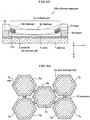
- a capacitor is formed by a bottom electrode 2 (which is an electrode on a substrate side and will be hereinafter also referred to also merely as an electrode 2) and a top electrode 3 (which is an electrode on an outer diaphragm layer 5b side and will be hereinafter also referred to merely as an electrode 3) which are provided respectively on a substrate 1 and on a flat outer diaphragm layer 5b with a cavity 4 therebetween.
- the direction where the ultrasonic transducer lOOp receives ultrasound (downward direction in Fig. 40 ) will be referred to as z direction
- the right direction in Fig. 40 will be referred to x direction
- the perpendicular downward direction with respect to the sheet of Fig. 40 will be referred to as y direction.
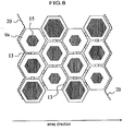
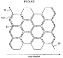
- a number of the above described transducers are disposed and arrayed, as shown in Fig. 43 , to be used.
- plural hexagonal ultrasonic transducers 100 are electrically connected by connection 13 arranged between ultrasonic transducers to form a single channel partitioned by shown dashed lines 20.
- Ultrasonic pulses are transmitted and received, utilizing ultrasonic transducers.
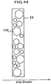
- the degree of freedom in controlling a device is advantageously increased, an example of which is that different frequencies can be selected, depending on the distance from an ultrasonic transducer to a subject. Therefore, a method is disclosed, in Patent Document 1, to achieve a broadband by simultaneously driving ultrasonic transducers 100, as shown in Fig. 44 , having respective diaphragms in different diameters, the ultrasonic transducers being connected by connections therebetween to serve as a single element 14.
- Patent Document 2 discloses a capacitive ultrasonic transducer reinforced by a stiffing layer at the central portion of a film.
- Patent Document 3 discloses an acoustic transducer with a structure, arranged above a cavity, having an insulating layer part and a top electrode which are disposed within the thickness dimension of a film.
- Non-patent Document 1 " A surface micromachined electrostatic ultrasonic air transducer", Proceedings of 1994 IEEE Ultrasonics Symposium, pp. 1241-1244
- JP 2005 110204 A discloses a capacitor microphone with microphone units using beams of varying configuration disposed on diaphragms allowing the microphone to cover a wide resonance frequency range.
- an ultrasonic probe configured with diaphragms in polygonal or circular shapes in different sizes packed in an area inevitably has gaps between ultrasonic transducers. These gaps make a problem of deteriorating the performance of the ultrasonic probe due to the following two causes.
- Reverberant sound may also be caused by the phenomenon that an ultrasound from a diaphragm passes through a portion not formed with a diaphragm, and this propagated ultrasound is reflected by the edge of an adjacent ultrasonic transducer, and finally returns to the original diaphragm.
- the upper limits of the sizes of respective ultrasonic transducers are defined by the disposition pitch for which diffraction of ultrasound and the like is taken into account, and the lower limits of the sizes are defined from a point of view of securing radiation impedance which achieves a required radiation efficiency. Therefore, the sizes of these ultrasonic transducers are selected usually from a narrow range in designing.
- Non-patent Document 1 since a semiconductor manufacturing technology is used for the above described conventional electrostatic transducer (described in Non-patent Document 1), masks corresponding to the planar shapes of diaphragms are used in a manufacturing process. There is a method of changing the frequency spectrum of a diaphragm, which changes the size (planar shape) of the diaphragm. However, it is necessary to design and manufacture a new mask for this method, which requires time and cost, causing a problem of decreasing the manufacturing efficiency.
- another method of changing the frequency spectrum of a diaphragm changes the thickness of the diaphragm.
- the thickness of the diaphragm which achieves a desired center frequency is substantially uniquely determined.
- the size and thickness of the diaphragm define the sensitivity and fractional bandwidth of this ultrasonic transducer. Consequently, there has been a problem that a desired frequency spectrum, namely, a combination of a center frequency and a fractional band width cannot be realized.
- an object of the present invention is to provide an ultrasonic transducer, ultrasonic probe, and ultrasonic imaging device having a simple structure and being capable of improving the performance of transmission and reception of ultrasound.
- the ultrasonic transducer of the present invention is defined in Claim 1. Further advantageous features are set out in the dependent claims.
- an ultrasonic probe which have a simple structure and are capable of improving the performance of transmission and reception of ultrasound are provided.
- an ultrasonic transducer a converter between electricity and ultrasound
- a transducer array a group of plural ultrasonic transducers in an array
- an ultrasonic imaging device will represent “an imaging device by the use of ultrasound provided with an ultrasonic probe, image former (means for forming an image from a signal obtained by an ultrasonic probe), display (means for displaying an image), controller, and the like”.
- Fig. 1 is a diagram showing an example of a structure of an ultrasonic imaging device using ultrasonic transducers in a first embodiment. Referring to Fig. 1 , the operation of the ultrasonic imaging device will be described.
- a transmission delay and weight selector 203 selects the values of a transmission delay time and a weight function for each channel to be supplied to a transmission beam-former 204. According to these values, the transmission beam-former 204 supplies an electro-acoustic conversion element 101 with transmission pulses through plural switches 205 for switching transmission/reception waves.
- an electro-acoustic conversion element 101 is also applied with a bias voltage by a bias voltage controller 202. As a result, the electro-acoustic conversion element 101 transmits ultrasound to a specimen, not shown here.
- a transmission/reception sequence controller 201 controls a reception beam-former 206 after a predetermined time has elapsed from the timing of transmission so as to start a reception mode.
- the predetermined time described above in a case of obtaining an image from a depth of a specimen deeper than 1 mm for example, is the turn around time for a sound to return a distance of 1 mm.
- the mode does not change to the reception mode immediately after transmission because the amplitude of the reception voltage is extremely smaller than the amplitude of the transmission voltage, being one hundredth to one thousandth.
- the reception beam-former 206 continuously controls the delay time and a weight function, corresponding to the arrival time of each reflected ultrasound, which is so-called a dynamic focus.
- Data after dynamic focus is converted into an image signal by image forming means including, for example, a filter 207, envelope detector 208, and scan converter 209, and then displayed on a display 210 as an ultrasonic tomographic image.
- a center frequency f c is a frequency with the highest electromechanical conversion efficiency (sensitivity) .
- a fractional bandwidth f h is, for example in a case of 3dB width, defined as a difference between two frequencies divided by the center frequency, wherein the sensitivity at these two frequencies is 3 dB lower than the sensitivity at the center frequency.
- a single ultrasonic transducer can be used for more various frequency bands, or ultrasonic pulses with a shorter time width can be formed, which achieves advantageous characteristics, such as obtaining a high distance resolution in a case of imaging by the use of ultrasonic beams.
- the center frequency f c of a diaphragm type ultrasonic transducer is substantially equal to the value of resonance frequency of the diaphragm, and is accordingly represented by following Expression (1), while the fractional bandwidth f h is represented by Expression (2), wherein the stiffness and the mass of the diaphragm are represented respectively by D and m.
- the stiffness and mass of an oscillation diaphragm are determined by the shape and dimensions of the oscillation diaphragm and the thickness thereof in a case of a solid material. Accordingly, in principle, by defining a proper shape and thickness of an oscillation diaphragm, a desired frequency spectrum can be obtained. However, only the two-degree-of-freedom of D and m for designing is not enough to optimize the three parameters of the center frequency, maximum value of sensitivity and fractional bandwidth.
- An ultrasonic probe for an ultrasonic imaging device for photographing common two-dimensional tomographic images performs fixed focusing by an acoustic lens in the direction (short axis direction) perpendicular to the tomographic plane, and performs electronic focusing of an ultrasonic beam at a desired position on the tomographic plane, having arrayed oscillators arranged in the direction (long axis direction) along the tomographic plane.
- ultrasonic transducers are arrayed ideally with a width of approximately a half of the wavelength at the center frequency of beams. For example, with a center frequency of 5 MHz, ultrasonic transducers are arrayed with a width of approximately 0.15 mm.
- the width along the short axis is preferably 7 to 8 mm.
- Patent Document 1 In the specification of United States Patent No. 5, 870, 351 (Patent Document 1), an example, as shown in Fig. 44 , is disclosed where a number of hexagonal shapes of diaphragms with different diameters are disposed in a single element which are electrically connected.
- Fig. 44 When circles or polygonal shapes with different diameters are packed in an area, there arises a problem that the packing efficiency drops.
- the pulse response of the element is greatly affected. This deterioration of pulse response will be described, referring to Fig. 45 . As shown in Fig.
- the total length of a path (arrow in the figure) on which an ultrasonic wave passes from one diaphragm through spaces where no diaphragm is formed, gets reflected by the surfaces of diaphragms adjacent to the one diaphragm, and returns to the one diaphragm is longer than in a case where hexagonal diaphragms with the same diameter are packed to form an array.
- Fig. 2 is a diagram of graphs showing a result of a simulation of a received ultrasonic pulse response by finite element method in a case of changing the distance between one diaphragm and adjacent diaphragms.
- a two dimensional model with diaphragms with a width of 60 ⁇ m and an unlimited length is employed.
- the material of the diaphragms is silicon nitride (SiN), and the thickness is 1.2 ⁇ m.
- Ultrasonic waves arriving from the front face of the array are sine waves with a center frequency of 10 MHz, and a cycle number of one periodic time.
- the horizontal axis represents time with an origin being the time when an ultrasonic pulse arriving from the front face of the array arrives at the surface of a diaphragm.
- the vertical axis represents the vertical velocity of the central portion of the diaphragm.
- the four graphs show the cases where the distance between adjacent diaphragms are 5 ⁇ m, 20 ⁇ m, 40 ⁇ m and 60 ⁇ m.
- the wider the distance between adjacent diaphragms the wider the pulse width.
- the diaphragm is deformed substantially the same as the waveform of an ultrasonic wave arriving from outside; the central portion of the diaphragm oscillates in a sine wave for one periodic time; thereafter (approximately 0.1 ⁇ sec later), the oscillation amplitude rapidly becomes small; the pulse width is narrow; and the frequency spectrum of the transmission function converting the ultrasonic wave to the deformation of the diaphragm is substantially flat.
- the wider the distance between the adjacent diaphragms the more the pulse waveform is extended.
- the pulse width is extended substantially 1.5 times compared with the case of the distance between adjacent diaphragms of 5 ⁇ m, showing that using an array in such conditions deteriorates the space resolution.
- Fig. 3 is a diagram of graphs showing waveforms of reception pulses in cases with the distance between adjacent diaphragms of 20 ⁇ m, 40 ⁇ m, and 60 ⁇ m, subtracted by a waveform of a reception pulse in a case of the distance between adjacent diaphragms of 5 ⁇ m.
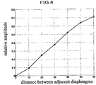
- the integrated values of the amplitudes of the reflected waves are represented by the vertical axis, and the distances between adjacent diaphragms are represented by the horizontal axis, in the graph in Fig. 4 .
- the vertical axis is normalized by the integrated value of the amplitude of the original reception waveform. It is shown that the value of the vertical axis becomes 0.1 or smaller where affects by a reflected wave can be almost neglected, when the distance between adjacent diaphragms is 10 ⁇ m or smaller.
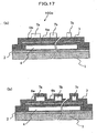
- Fig. 46(a) and 46(b) illustrate the mechanism in which an ultrasonic wave entering a substrate from a gap between diaphragms generates a noise.
- Fig. 46(a) is a schematic cross-sectional view of a diaphragm and the peripheral
- Fig. 46 (b) is a diagram showing the temporal change in a gain voltage signal.
- an ultrasonic pulse A having directly entered a diaphragm is first converted into an electrical signal, as shown as A in the graph with the horizontal axis of time and the vertical axis of echo voltage signal in Fig. 46(b) .
- an ultrasonic pulse B having arrived in a region of a gap between diaphragms, as shown by paths a, b and c in Fig. 46 (a) repeats multiple reflections in the substrate, passes through a limb portion of a diaphragm, and arrives at the diaphragm.
- the ultrasonic pulse having passed through the paths a, b and c is also converted into an electric signal by deforming the diaphragm, and appears as an electric signal with waveforms B, B' and B" as shown in Fig. 46(b) .
- an ultrasonic imaging device in a case, for example, of observing the inner structure of a blood vessel, in order to observe sites of which reflectance intensities differ from each other by 40 dB to 60 dB, such as the tissue site of the blood vessel and the lumen of the blood vessel, an image of the structure is created by compressing the brightness and with a wide dynamic range. Therefore, even if the echo of B and B' are imperceptible, when echo of delayed B and B' accompanies the reflectance signal A from the tissue site of the blood vessel, the echo is observed as an image inside the blood vessel, which does not allow distinction between a plaque in the blood vessel and a false image of B or the like.
- the amplitude of a reflectance signal B is necessary to be reduced to one thousandth, namely approximately -60 dB, compared with the amplitude of a reflectance signal A.
- the transmission efficiency of a sound through the gap drops and effect by a reverberant sound, such as B, does not become a problem.
- the shapes and structures of diaphragms are adopted which are suitable for making the resonance frequencies differ from each other to widen the fractional bandwidth, while minimizing the areas of gaps between diaphragms.
- Fig. 5 shows an example of an ultrasonic probe in the present embodiment, and is a top view showing a part of a semiconductor diaphragm type transducer array configuring the ultrasonic probe.
- Fig. 6 is a schematic diagram showing an oblique top view of one of the diaphragm type ultrasonic transducers in the array shown in Fig. 5 , the one being cut for viewing.
- Each diaphragm type ultrasonic transducer is, as shown in Fig. 6 , includes a bottom electrode 2 (the first electrode) formed on a substrate 1, an inner diaphragm layer 5a being formed on the bottom electrode 2 and having a cavity 4 therein, a top electrode 3 (the second electrode) provided on the inner diaphragm layer 5a, and an outer diaphragm layer 5b, which are disposed in this order, and a beam 7 connecting opposite apexes of the diaphragm, the beam being formed on the outer diaphragm layer 5b.
- the bottom electrode 2 and the top electrode 3 are facing each other through the inner diaphragm layer 5a having the cavity 4 therein, and configure a capacitor.
- a film in a homothetic shape of the diaphragm is formed to be continuous with the beam 7.
- both or either the inner diaphragm layer 5a or the outer diaphragm layer 5b may be described merely as “diaphragm” . Further, symbols of other elements may be omitted.
- a diaphragm type ultrasonic transducer applying a high DC bias improves the sensitivity of transmission and reception because more charges are accumulated. However, if an excessive DC bias is applied, a part of the diaphragm comes in contact with the opposite surface of the cavity 4.
- Such a contact causes charge emission into the diaphragm, and drifts the electro-acoustic conversion characteristics of the element.
- the contact starts at the gaps between the beams 7 and a portion adjacent to the center of the diaphragm.
- the diameter of the homothetic shape is preferably approximately 50% to 80% of the diameter of the entire diaphragm.
- the beams 7 have a structure having a smaller width compared with the length and a shape covering only a part of the diaphragm.
- the beams 7 effect the resonance frequency of the diaphragm type entire ultrasonic transducer, by having the hardness conditions described below. That is, the hardness of the beams 7 is made great enough compared with the hardness of the material of the diaphragm portion forming the upper wall of the cavity 4, or the thickness of the beams 7 is made great enough compared with the thickness of the diaphragm portion.
- the resonance frequency of the diaphragm type entire ultrasonic transducer can be controlled by the shape and material of the beam 7.
- the resonance frequency f b in the thickness direction is represented by the following Expression (3).
- E denotes Young's Module
- I denotes the cross-sectional moment
- m denotes the mass.
- Equation (3) is equivalent to Equation (4).
- Equation (4) is a proportional expression, coefficients are omitted.
- the resonance frequency f b is proportional to the square root of the width W.
- the beams 7 are in a rectangular solid shape with a width of W at the marginal portion, and are in a homothetic shape of the diaphragm, as shown in Figs. 5 and 6 , at the central portion of the diaphragm, assuming that the central portion of the diaphragm to be approximately a spindle with a mass of M, Expression (3) is described as Expression (5), and almost the same case as described above is applicable.
- Expression (3) is described as Expression (5), and almost the same case as described above is applicable.
- the resonance frequency of a diaphragm can be controlled by the width W of beams 7 in such a manner, then, by packing ultrasonic transducers having diaphragms with a constant diameter and beams 7 with different widths W provided on the front surfaces or back surfaces of the respective diaphragms, as shown in Fig. 5 , it is possible to configure a single ultrasonic transducer with diaphragm type plural ultrasonic transducers with different resonance frequencies, without gaps between the diaphragms.
- the boundary of an ultrasonic transducer that functions as a single element is shown by dashed lines 20.
- the bottom electrode 2 is common to the diaphragm type plural ultrasonic transducers configuring the single ultrasonic transducer, and the top electrodes of the diaphragm type plural ultrasonic transducers configuring the single ultrasonic transducer are electrically connected mutually by connections 13.
- a substrate 1 is made of silicon and a bottom electrode 2 with a thickness of approximately 500 nm and made of metal or polysilicon is formed on the silicon substrate.
- a bottom electrode 2 with a thickness of approximately 500 nm and made of metal or polysilicon is formed on the silicon substrate.
- an insulation film of silicon oxide or the like is formed with a thickness of approximately 50 nm on which a cavity 4 with a dimension in the thickness direction of approximately 200 nm is formed.
- An insulation film (the first diaphragm) 5 is formed with a thickness of approximately 100 nm to form the upper wall of the cavity 4, and a top electrode 3 is formed with a thickness of approximately 400 nm of metal such as aluminum on the insulation film 5.
- an outer diaphragm layer 5b with a thickness of approximately 200 nm of silicon nitride to cover the entire cavity 4, and further on the outer diaphragm layer 5b, formed is a film of silicon nitride with a thickness of approximately 1000 nm to form beams 7.
- the center frequency is 7.8 MHz and -6 dB fractional bandwidth is 120% (-6 dB fractional band is 3 to 12.5 MHz) with W 1 of 0.5 ⁇ m
- the center frequency is 10 MHz and -6 dB fractional bandwidth is 100% (-6 dB fractional band is 5 to 15 MHz) with W 2 of 4 ⁇ m
- the center frequency is 11.5 MHz and -6 dB fractional bandwidth is 96% (-6 dB fractional band is 6 to 17 MHz) with W 3 of 20 ⁇ m.
- -6 dB band becomes 3 to 17 MHz, that is, -6 dB fractional bandwidth becomes 140%.
- -6 dB fractional bandwidth is improved by 40 to 20 points.
- a film in a homothetic shape of the diaphragm in a polygonal shape is formed at the central portion of the diaphragm continuously with the beams 7.
- the same effect can be obtained of course.
- it is also possible to set different resonance frequencies of individual diaphragms by providing hard regions 15 in the respective central portions of the diaphragms and changing the sizes of the hard regions 15, without changing the size of the entire diaphragms.
- a structure in which beams 7 having different widths and connecting opposite apexes of diaphragms in a polygonal shape are formed on the front surfaces or back surfaces of diaphragms, as shown in Fig. 5 and Fig. 7 .
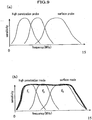
- Fig. 9(a) is an illustration on how to select frequencies for respective observation sites, in a case of using a conventional probe with a fractional bandwidth of approximately 60%.
- attenuation accompanying propagation of an ultrasound becomes greater substantially proportionally to the frequency. Therefore, in a case of observing with high penetration into a specimen, almost no signal returns due to attenuation.
- an optimum frequency is substantially automatically determined, wherein selected are frequencies of approximately 2 MHz for observation at a depth of 15 to 20 cm from a body surface (such as a liver), approximately 10 MHz for observation at a depth of several centimeters from the body surface (such as a thyroid), and higher for a case such as a probe in a blood vessel.
- the element width is necessary to be switchable. Switching of the element width is determined when an object site is selected.
- the element width is constant in a single imaging plane.
- the object site is relatively large and the element width is necessary to be changed even in a single screen depending on the place to set the object site.
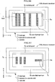
- the object site is extending from a vicinity of the body surface to a deep portion and the element width is necessary to be switched accompanying the movement of the focus position while receiving ultrasound. For example, a case of switching the element width while receiving ultrasound will be described, referring to a device diagram.
- An ultrasonic pulse in a wide band is applied from a transmission beam-former 204 in Fig. 1 through a switch 205 and sub-element cross point switch 17 to an ultrasonic probe configured with sub-elements 16, and the ultrasonic pulse is transmitted to a specimen not shown.
- the transmission beam-former 204 improving signal/noise ratio by widely transmitting ultrasonic pulses is more important than increasing the space resolution by narrowing the beam. Therefore, the number of sub-elements per channel is set small, and the total aperture is set narrow. Since ultrasounds scattered in a specimen return in order of nearness to the surface of the specimen, ultrasounds return in ascending order of the propagation distance in the specimen. In a conventional technology, ultrasounds returning from the specimen are received by reception beam-former 206 through the switch 205; the delay time and weight coefficient are adjusted between channels; and a tomographic image is displayed through an envelope detector and a scan converter.
- a sub-element cross point switch 17 between the sub-elements 16 and the switch 205 when ultrasounds from near-surface portions are received, sub-elements are bundled in the quantity corresponding to the upper end of the band having transmitted the ultrasounds, and when ultrasounds from deeper portions are received, sub-elements are bundled in the quantity corresponding to the lower end of the band having transmitted the ultrasounds.
- the time is continuous from when ultrasounds are received from the near-surface portions until when ultrasounds are received from deeper portions, and accordingly, switching of the quantity of sub-elements is necessary to be carried out continuously in terms of time.
- diaphragms in a hexagonal shape are connected criss-crossingly to form an ultrasonic transducer of a single electrical element.
- the element width can be changed corresponding to the mode.
- the mode is imaging conditions automatically determined by the depth of the object site.
- the photograhing conditions include the drive frequency, cut-off value of the frequency filter for reception, the number of transmission sine waves, temporal weight function, aperture weight function, and the like.
- the range of the depth of imaging is usually determined, and the degree of attenuation of propagation medium can be estimated. Accordingly, various conditions, such as an optimum frequency, are determined.
- an optimum frequency is determined.
- the object site often extends from a near portion to a far portion even if the object site is determined. Therefore, in some cases, plural modes are applied even for a single object site, and the modes are automatically switched depending on the depth generated by a reflected echo.
- Sub-elements are configured by a group of diaphragm type ultrasonic transducers of which top electrodes are permanently connected by conductors.
- the sub-element When a sub-element configures one element for beam forming, the sub-element serves as a unit of ultrasonic transducer bundled by a switchable switch.
- dashed lines 20 show the boundaries between sub-elements of ultrasonic transducers which are electrically connected.
- Fig. 10 four sub-elements 16a to 16d are shown which are electrically connected in a direction perpendicular to the array direction.
- an element width of 0.55 mm being 75% of a wavelength at 2 MHz can be achieved by 11 rows of diaphragms with a diameter of 50 ⁇ m, and the element width of 55 ⁇ m being 75% of a wavelength at 20 MHz can be achieved by one row of diaphragms with a diameter of 50 ⁇ m, which achieves an optimal element pitch for each mode in the range from 2 MHz to 20 MHz.
- an element width of 0.55 mm can be attained by simultaneously driving eleven bundled adjacent sub-elements as one element, and when driving an ultrasonic probe at 20 MHz, an element width of 55 ⁇ m can be attained by driving individual sub-elements independently.
- Fig. 11 is a diagram specifically illustrating how to change the number of sub-elements to be bundled and an effect of it.
- Fig. 11(a) shows the state where the focus of a transmission wave or reception wave is set to the nearest distance Fn.
- the total aperture width Wn Ws x N for a system with the number of channels N.
- Fig. 11b shows a state where the focus is set to a deeper distance Ff.
- F value in other words, focal length/ aperture width can be maintained to be substantially constant. Accordingly, compared with a case where the element width and the number of channels are constant, it is possible to inhibit generation of grating lobes (unnecessary emission) due to a too small F value at a near distance. Also, at a far distance, defocusing due to a too large F value can be inhibited.
- This sub-element cross point switch can be mounted in the ultrasonic imaging device.
- the number of cables 18 can be reduced to the necessity minimum by providing a sub-element cross point switch 17 on the sub-elements 16 side, rather than arranging cables 18 connecting the connector 19 in connection with the ultrasonic imaging device and the ultrasonic transducers.
- Fig. 13(a) is a schematic plan view showing an example of an ultrasonic probe using diaphragm type ultrasonic transducers having a rectangular diaphragm.
- Fig. 14 is a cross-sectional view along the array direction. As shown in Fig. 14 , with a structure where the widths of the cavity portions are different from each other, plural diaphragms having different resonance frequencies can be provided in an electrically connected single element.
- plural diaphragms each of which is an element configuring the respective diaphragm type ultrasonic transducer, are disposed in such a manner that the longer sides of the diaphragms are in the same direction as the longer sides of a single electrically connected element 14, namely, in the direction perpendicular to the array direction of the transducer array.
- a top electrode substantially in the same shape as the diaphragm and a cavity are provided, and a common (shared) bottom electrode arranged below the cavity and the top electrode configure a capacitor.
- each ultrasonic transducer provided with a rectangular diaphragm has a resonance frequency defined by the length of shorter sides of the diaphragm.
- a single ultrasonic transducer can be obtained in which plural diaphragms, which are disposed without a gap therebetween and have different center frequencies, are simultaneously driven electrically, by selecting a combination of the lengths of the shorter sides of diaphragms such as to divide the shorter side of the electrically connected single element 14 into plural parts.
- the center frequency is 7.8 MHz and the -6 dB fractional bandwidth is 120% (-6 dB fractional band is 3 to 12.5 MHz) for W 1 of 60 ⁇ m
- the center frequency is 10 MHz and the -6 dB fractional bandwidth is 100% (-6 dB fractional band is 5 to 15 MHz) for W 2 of 50 ⁇ m
- the center frequency is 11.5 MHz and the -6 dB fractional bandwidth is 100% (-6 dB fractional band is 6 to 17 MHz) for W 3 of 40 ⁇ m.
- -6 dB band becomes 1 to 15 MHz, that is, -6 dB fractional bandwidth becomes 140%. Since -6 dB fractional bandwidth of a conventional known diaphragm structure is approximately 100 to 120%, -6 dB fractional bandwidth is improved by 20 to 40 points.
- Fig. 13(b) is a schematic plan view showing another example of an ultrasonic probe using a diaphragm type transducer array, the diaphragms being rectangular.
- this ultrasound probe plural diaphragms each of which is an element configuring the respective ultrasonic transducer are disposed in such a manner that the longer sides of them are in the same direction as the shorter sides of an electrically single element 14, in other words, in the same direction as the array direction of the transducer array.
- a top electrode substantially in the same shape as the diaphragm and a cavity are provided, and a common bottom electrode arranged below the cavity and the top electrode configure a capacitor.
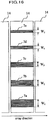
- Fig. 15 setting such as to allow free changing of the element width along the array long axis direction, depending on the mode, is advantageous in a viewpoint of fully utilizing the wide band characteristics of an ultrasonic probe.
- plural ultrasonic transducers are connected only along the direction perpendicular to the array direction and a number of sib-elements are formed, and the element width along the array long axis is changed by changing bundling of sub-elements.
- Fig. 15 plural ultrasonic transducers are connected only along the direction perpendicular to the array direction and a number of sib-elements are formed, and the element width along the array long axis is changed by changing bundling of sub-elements.
- Fig. 16 is a schematic plan view of an ultrasonic transducer in a second embodiment.
- Fig. 17(a) is a schematic cross-sectional view of it.
- an ultrasonic transducer 100q having a wide band can be realized.
- an element driven by a single electric signal in other words, a single electric element, is configured with a single diaphragm, wherein the bandwidth as the entire diaphragm is widened by aligning plural beams 7 having different center frequencies on the single diaphragm.
- plural rectangular beams 7a to 7e are formed crossing the short side direction of diaphragms, on a rectangular outer diaphragm layer 5b configuring a single ultrasonic transducer.
- the widths of the shorter sides of the beams 7a, 7b, 7c, 7d, and 7e are respectively W1, W2, W3, W4and W5, and the widths W1to W5are different from each other.
- the relationship between the diaphragm and the beams 7 is the same as the relationship between W1, W2 and W3, in Fig. 5 , and the resonance frequencies.
- beams with different widths may be embedded inside the outer diaphragm layer 5b.
- beams 7 having respective center frequencies are disposed with periodicity as little as possible, the same as described above, with care not to form grating lobes (unnecessary emission).
- a 1.5-dimensional array has a structure for which an array is arranged also along the direction (long axis) for scanning the position or direction of an ultrasonic beam, in other words, along the direction (short axis) perpendicular to the imaging plane, and thereby focusing along the short axis can be made variable.
- Fig. 18 is a vertical cross-sectional view showing an ultrasonic transducer 100 in the third embodiment.
- Fig. 19 is a plan view showing the ultrasonic transducer 100.
- the direction where the ultrasonic transducer 100 receives ultrasound namely, the downward direction in Fig. 18 and the perpendicular downward direction with respect to the sheet of Fig. 19 will be referred to as z direction.
- z direction the direction where the ultrasonic transducer 100 receives ultrasound
- x direction the direction where the ultrasonic transducer 100 receives ultrasound
- y direction the perpendicular downward direction with respect to Fig. 18 , which is also the upward direction in Fig. 19
- this ultrasonic transducer 100 is an electrostatic diaphragm transducer including a flat plate shaped substrate 1 of insulating material, such as a monocrystalline silicon, or semiconductor material, an electrode 2 disposed on the top of the substrate 1 and formed of a conductive material, such as aluminum, in a thin film shape, a diaphragm 5 disposed on the top surface of the electrode 2 and formed in a thin plate shape, and one or plural beams 7 formed on the top of the diaphragm 5.
- insulating material such as a monocrystalline silicon, or semiconductor material
- an electrode 2 disposed on the top of the substrate 1 and formed of a conductive material, such as aluminum, in a thin film shape
- a diaphragm 5 disposed on the top surface of the electrode 2 and formed in a thin plate shape
- one or plural beams 7 formed on the top of the diaphragm 5 formed on the top of the diaphragm 5.
- the surface which is provided with the diaphragm 5 and transmits ultrasound will be referred to as the top surface and the surface on the side of the substrate 1 will be referred to as the bottom surface.
- the diaphragm 5 has a cavity 4 therein, and the portion covering the top of the cavity 4 forms an oscillating part 5c for generating ultrasound by oscillation.
- the diaphragm 5 includes the cavity 4 making the distance between the oscillating part 5c of the diaphragm 5 and the electrode 2 on the substrate 1 side, and provided with an inner diaphragm layer 5b which causes insulation so that the electrode 2 on the substrate 1 side and an electrode 3 (described later) on the diaphragm 5 side are not electrically conducted with each other even when the oscillating part 5c is deformed excessively, an outer diaphragm 5b formed such as to cover the top surface of the inner diaphragm 5a, and the electrode 3 disposed on the diaphragm 5 side and formed of the same material as the electrode 2 and in a thin film shape between the inner diaphragm layer 5a and the outer diaphragm layer 5b.
- diaphragms 5 and beams 7 are those described in United States Patent No. 6,359, 367 , for example.
- Examples are silicon, sapphire, any sort of glass material, polymers (such as polyimide), polysilicon, silicon nitride, silicon oxynitride, thin film metals (such as aluminum alloys, copper alloys and tungsten), spin-on-glasses (SOGs), implantable or diffused dopants and grown films such as silicon oxides and silicon nitrides.
- the distance between the oscillating part 5c of the diaphragm 5 and the substrate 1, that is the thickness of the cavity 4 (dimension in z direction) is maintained mainly by the stiffness in the upper and lower direction (z direction) of both or either the inner diaphragm layer 5a or the outer diaphragm layer 5b. Further, this stiffness is reinforced in a predetermined direction by the beams 7.
- a significant feature of an ultrasonic transducer 100 in the present embodiment is that beams 7 are arranged on a diaphragm 5, and the stiffness of the diaphragm 5 is adjusted.
- a desired combination of a resonance frequency f b and a fractional bandwidth f h can be achieved by appropriately setting the combination of the thickness (the length along z direction) of the diaphragm 5 and the thickness (the length in z direction) of the beams 7.
- this ultrasonic transducer 100 acts as a variable capacity capacitor having an electrode 2 on the substrate 1 side and an electrode 3 on the diaphragm 5 side, the both electrodes serving as polar plates, with the cavity 4 disposed therebetween and functioning as a dielectric.
- the diaphragm 5 when a force is applied to the diaphragm 5, the diaphragm is displaced and thereby the distance between the electrode 2 and electrode 3 changes, thus the capacitance of the capacitor changes.
- a difference in potential is applied to the electrode 2 and electrode 3
- respective opposite charges are accumulated in them to cause forces acting on each other, and thus the diaphragm 5 is displaced.
- the ultrasonic transducer 100 is an electro-acoustic conversion element that converts a high frequency electric signal, which has been input, into an ultrasonic signal and emits the ultrasonic signal to a medium, such as water or a living organism, and then converts an ultrasonic signal being input from the medium into a high frequency electric signal and outputs the high frequency electric signal.
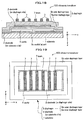
- Fig. 20 is a perspective view showing a transducer array 1000.
- This transducer array 1000 serves as the ultrasound transmission/reception surface of an ultrasonic probe (not shown), and is formed with a number of ultrasonic transducers 100, described above, on a substrate 1, the ultrasonic transducer 100 being connected by connections 13 by the unit of a predetermined number.
- the number of the ultrasonic transducers 100 is not limited to the number shown, and ultrasonic transducers 100 in an even greater number may be integrated on a larger substrate 1, depending on a semiconductor manufacturing technology.
- ultrasonic transducers 100 or ultrasonic transducers 100 bundled by a unit of predetermined number are connected through a transmission and reception switch to a transmission beam-former and a reception beam-former (both not shown) of an ultrasonic imaging device provided with this ultrasonic probe, and acts as a phased array to be utilized for transmission and reception of ultrasounds.
- the shown array of the ultrasonic transducer 100 is an example, and other forms of arrays may be arranged, including a honeycomb shape and grid shape. Further, the array surface may be either a flat surface or curved surface, and the outline of the surface may be formed in a circle shape, polygonal shape, or the like. Or, the ultrasonic transducers 100 may be disposed on a line or a curve.
- This ultrasonic probe is provided with a transducer array 1000 formed, for example, in an array shape having a plurality of groups of ultrasonic transducers 100 arrayed on a line, or formed in a convex type having a plurality of ultrasonic transducers 100 arrayed in a fan shape. Further, on the medium (specimen) side of the ultrasonic transducers 100 of this ultrasonic probe, there are arranged an acoustic lens for convergence of ultrasonic beams, and an acoustic matching layer for matching the acoustic impedance between the ultrasonic transducers 100 and the medium (specimen) . Further, on the back side (reverse side with respect to the medium side), a packing member for absorbing propagation of ultrasonic waves is arranged.
- Fig. 21 is a diagram of a graph showing an example of frequency versus gain response of an ultrasonic transducer 100.
- the horizontal axis represents frequency f
- the vertical axis represents sensitivity G (Gain) indicating electro-mechanical conversion efficiency.
- frequency f at which the sensitivity G is the highest is defined as peak frequency f p
- the range where sensitivity G is not smaller than -3 [dB] from the highest value is defined as the frequency bandwidth f w .
- the frequency at the center of frequency bandwidth f w is defined as center frequency f c , and the value of frequency bandwidth f w divided by center frequency f c (in other words, the value of frequency bandwidth f w normalized by center frequency f c ) is defined as fractional bandwidth f h (not shown).
- Gain G means the efficiency of mutual conversion between electric energy and mechanical energy, such as mechanical energy of a sound wave. Accordingly, in view of increasing the transmission efficiency and detecting faint sound wave signals, gain G of the ultrasonic transducers 100 is desired to be high.
- the fractional bandwidth f h is another one of the significant characteristics of the ultrasonic transducers 100 .
- the greater the fractional bandwidth f h the wider the usable frequency range, and thus a single ultrasonic transducer 100 can be used for various purposes, which is an advantage of the ultrasonic transducer 100.
- the fractional band width f h is greater, ultrasonic pulses with narrower pulse widths (in other words, the occupied frequency band width is wider) can be formed, which is an advantage achieving high distance resolution in ultrasonic imaging.
- an ultrasonic transducer 100 is a diaphragm type
- the center frequency f c and the resonance frequency f b are substantially the same.
- the resonance frequency fb, stiffness D and mass m of a diaphragm 5 have relationship in Expression (1).
- Fractional band width f h has a relationship in Expression (2).
- the stiffness D and mass m of a diaphragm 5 are defined by the planar shape and thickness thereof when the material is determined in advance. Accordingly, if both the planar shape and the thickness of the diaphragm 5 can be properly set, a desired frequency spectrum (combination of the center frequency f c ( ⁇ resonance frequency f b ) and the fractional band width f h ) can me obtained.
- Fig. 22 is a schematic diagram showing a bending state of a beam 7.
- the beam 7 is in a rectangular solid shape with a width of w, length of v and thickness of t when no force is applied.
- the stiffness D in the thickness direction (oscillation direction of the diaphragm 5: z direction) of the beam 7 has the following relation in Expression (6), wherein the mass of the beam 7 is represented by m, and the Young's Module is represented by E. D ⁇ Ew t v 3
- the resonance frequency f b in the thickness direction t (z direction; oscillation direction of the diaphragm 5) of the beam 7 has the relationship of the following Expression (8).
- f b 2 ⁇ D m Et 2 ⁇ v 4
- the resonance frequency f b of the beam 7 is proportional to the thickness t.
- the thickness t is uniquely determined, when the planar shape (width w and length v) is determined in advance. Further, if the material and respective dimensions of the beam 7 are determined, then the mass m is also determined, and thereby the fractional band width f h is also uniquely determined. Still further, this description on the beam 7 is also true in the case of parts which can be assumed to be a rectangular homogeneous solid shape, for example, the oscillating part 5c (the flat shaped portion excluding the beams 7) of the diaphragm 5.
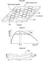
- Fig. 23 is a perspective view schematically showing an oscillating body 6a in accordance with the invention, and an oscillating body 6b in a comparative example.
- the oscillating body 6a in accordance by the invention follows the oscillating part 5c of the diaphragm 5 in the third embodiment, and is provided with a base plate 20a in a flat plate form and a single beam 7d on the base plate 20a.
- the thickness of the base plate 20a is t 1
- the thickness of the beam 7d is t 2 .
- the oscillating body 6b of the comparative example has a shape of the above described oscillating body 6a without the beam 7, and formed of a base plate 20b in a flat plate form.
- the thickness of the base plate 20b is t 0 .
- the length (dimension in y direction) of the base plate 20a and beam 7d of the oscillating body 6a and the length of the base plate 20b of the oscillating body 6b are both v.
- the both widths (dimension in x direction) of the base plate 20a and the base plate 20b are w 1
- the width (dimension in x direction) of the beam 7d is w 2 .
- the materials of the base plate 20a, base plate 20b, and beam 7d are all the same.
- Fig. 24 is a diagram of graphs showing a result of calculation of resonance frequencies f b and fractional bandwidths f h in a case where the width w 2 of the beam 7d of an oscillating body 6a in accordance with the invention is set to 20 percent of the width w 1 of a base plate 20a.
- the horizontal axis indicates the thickness ratio t 2 /t 0 of a beam, namely, the value of the thickness t 2 of the beam 7d of the oscillating body 6a normalized by the thickness t 0 of the base plate 20b of an oscillating body 6b.
- the vertical axis indicates the thickness ratio t 1 /t 0 , namely, the thickness t 1 of the base plate 20a of the oscillating body 6a normalized likewise by the thickness t 0 of the base plate 20b of the oscillating body 6b.
- Each solid graph represents the value of the resonance frequency f b of oscillating bodies 6a in accordance with the invention normalized by the resonance frequency f b of an oscillating body 6b of a comparative example.
- the numeral given to each solid graph indicates the value of a normalized resonance frequency f b , wherein the values of normalized resonance frequencies f b are all the same at arbitrary positions on a same solid graph.
- Each dashed graph represents the fractional bandwidth f h of oscillating bodies 6a in accordance with the invention normalized by the fractional bandwidth f b of the oscillating body 6b of the comparative example.
- the numeral given to each dashed graph indicates the value of a normalized fractional bandwidth f h , wherein the values of normalized fractional bandwidths f h are all the same at arbitrary positions on a same dashed line.
- this oscillating body 6a is equivalent to a base plate 20b with a thickness of t 0 of a comparative example. That is, the thickness ratio t 1 /t 0 of the base plate 20a of this oscillating body 6a is set to 1.0, and the thickness ratio t 2 /t 0 of the beam 7d is set to 0.0.
- a combination of a thickness ratio t 1 /t 0 and a thickness ratio t 2 /t 0 is selected such that the value of the normalized resonance frequency f b is 1.0 (moving on a solid graph given with "1.0"), and thus the thickness t 1 of a base plate 20a and the thickness t 2 of a beam 7d can be obtained.
- a combination, which achieves the desired normalized value of a fractional bandwidth f h , of a thickness ratio t 1 /t 0 and a thickness ratio t 2 /t 0 is selected with the value of a normalized resonance frequency f b be 2.0 (moving on the solid graph given with "2.0" and finding the intersection point between this solid graph and a dashed graph given with the desired normalized value of a fractional bandwidth f h ), and thus the thickness t 1 of a base plate 20a and the thickness t 2 of a beam 7d can be obtained.
- an oscillating body 6a has a structure provided with a beam 7d on a base plate 20a, by properly setting the respective thicknesses (dimension in z direction) of these elements (the base plate 20a and the beam 7d), a desired frequency spectrum (a combination of a resonance frequency f b and a fractional bandwidth f h ) can be realized, even without changing the planar shape of these elements.
- Fig. 25 is a diagram of graphs showing a result of calculation of resonance frequencies f b and fractional bandwidths f h in a case where the width w 2 of the beam 7d of an oscillating body 6a in accordance with the invention is set to 80 percent of the width w 1 of a base plate 20a.
- Comparison of Fig. 24 and Fig. 25 proves that, if the ratio of the width w 2 of the beam 7d of an oscillating body 6a to the width w 1 of a base plate 20a is different from that in another case while the thickness t 2 of the beam 7d and the thickness t 1 of the base plate 20a are changed in the same way as in the other case, the frequency spectrum changes differently from the other case.
- the width w 2 of the beam 7d is increased having the width w 1 of the base plate 20a be constant, the planar shape of the beam 7d and the planar shape of the base plate 20a become closer to each other. Accordingly, if the resonance frequency f b is maintained constant, the adjustable range of the fractional bandwidth f h achieved by selecting a combination of the thickness t 1 of the base plate 20a and the thickness t 2 of the beam 7d becomes narrower.
- the width w2 of the beam 7d is made as small as possible compared with the width w1 of a base plate 20a in a range allowed by manufacturability.
- the material of the base plate 20a and the material of a beam 7d are the same, however, the same effect can be achieved also using different materials.
- Fig. 26 is a schematic perspective view showing a beam 7d of a modified example.
- This beam 7b is configured with a beam part 7ba with a width of w 2 , the beam part 7ba being a part of the beam 7b, and a beam part 7bb with a different width of w 22 , the beam part 7bb being another part of the beam 7b, wherein the beam parts 7ba and 7bb are joined with each other with respect to the thickness direction (z direction) with the same long axis direction.
- the thickness t 21 of the beam part 7ba and the thickness t 22 of the beam part 7bb can be selected independently.
- the fractional bandwidth f h can be continuously changed by changing the combination of the thickness t 21 of the beam part 7ba and the thickness t 22 of the beam part 7bb.
- Fig. 27 is a perspective view showing the shapes of a beam 7c1, 7c2 and 7c3 of other modified examples.
- the beam 7c1 having a cross-section in a triangle shape may be employed.
- the beam 7c2 having a cross-section in a trapezoidal shape may be employed.
- the beam 7c3 of which width changes along the long axis direction may be employed.
- the beam may have a rectangular solid shape, in other words, a shape with rectangular cross-sections in the short and long axis directions, or any other shape as long as the thickness (dimension along the oscillation direction of the diaphragm 5, namely, z direction) can be controlled during a manufacturing process.
- the beam may have a cross-section in a polygonal shape, such as a triangular, rectangular, trapezoidal or another quadrilateral shape, or a cross-section, such as a circular, ellipsoidal shape or the like, or a cross-section which changes along a certain direction.
- Ultrasonic transducers 100b to 1001 in the later described fourth to fourteenth embodiments can also be used in the ultrasonic probe described above.
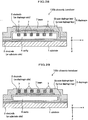
- Fig. 28 is a vertical cross-sectional view showing an ultrasonic transducer 100b in a fourth embodiment.
- This ultrasonic transducer 100b has a structure having beams 7 inside a cavity 4 of a diaphragm 5 (inner diaphragm layer 5a). That is, in the present embodiment, the beams 7 are disposed adjacent to an electrode 3 on the surface of the diaphragm 5 and on the side facing an electrode 2 on the substrate 1 side.
- This ultrasonic transducer 100b has the same effects as in the third embodiment, and allows the surfaces of the diaphragm 5 to be flat.
- Fig. 29 is a vertical cross-sectional view showing an ultrasonic transducer 100c in a fifth embodiment.
- This ultrasonic transducer 100c has a structure having beams 7 implanted in the substrate of a diaphragm 5 (more specifically, an outer diaphragm layer 5b). These beams 7 are formed of a material having a higher stiffness (the Young's Module) than that of the diaphragm 5 or a material having a lower stiffness than that of the diaphragm 5. Or, the beams 7 may be formed by cavities with vacuum therein or with air or another kind of gas charged therein.
- the direction and the amplitude of the stiffness of the diaphragm 5 can be adjusted as desired to change the stiffness, without changing the shape or thickness of the diaphragm 5. Further, the electro-acoustic efficiency can be increased by narrowing the distance between the electrode 2 and electrode 3.
- the beams 7 may be formed directly inside the inner diaphragm layer 5a or the outer diaphragm layer 5b, or may be formed by arranging recessions on the surface of the inner diaphragm layer 5a or the outer diaphragm layer 5b and joining the inner diaphragm layer 5a and the outer diaphragm layer 5b to seal these recessions.
- Fig. 30 is a vertical cross-sectional view showing an ultrasonic transducer 100d in a sixth embodiment.
- This ultrasonic transducer 100d has a structure having a beam 7z instead of the above described electrode 3 on the diaphragm side and beams 7.
- This beam 7z is formed, for example, of the same material as the above described electrode 3 on the diaphragm 5 side, or of another conductive material, and includes an electrode layer part 7zb in the same shape as the above described electrode 3 on the diaphragm 5 side, the electrode layer part 7zb being a part of the beam 7z, and beam parts 7za having a shape elongated along shown y direction and increasing the stiffness of the diaphragm 5 in y direction, each beam part 7za also being a part of the beam 7z.
- the beam parts 7za may be disposed in a grid pattern for example, without being limited to a single direction.
- the manufacturing process can be simplified and the structure can be hardened.
- this ultrasonic transducer 100d may have a structure which secures the most of the stiffness of the diaphragm 5 by the beam 7z serving also as an electrode and either the inner diaphragm layer 5a or the outer diaphragm layer 5b. Accordingly, either the inner diaphragm layer 5a or the outer diaphragm layer 5b is not required to take the role of securing the stiffness, and can be thinned or omitted. If the beam 7z secures most of the stiffness, the inner diaphragm 5a is unnecessary in principle. This allows narrowing the distance between the electrode 2 and the electrode 3 and improving the electro-acoustic conversion efficiency.
- the outer diaphragm layer 5b may have a thickness enough for protection or insulation.
- the manufacturing process can be simplified, and the distance between the electro-acoustic conversion section, configured by the beam 7z and the electrode 2 on the substrate 1 side, and a measured medium (not shown) can be shortened, which improves the sensitivity.
- Fig. 31 is a vertical cross-sectional view showing an ultrasonic transducer 100e in a seventh embodiment.
- this ultrasonic transducer 100e has a structure having a beam 7n formed of a material with a lower stiffness than that of a diaphragm 5 or formed as a cavity, adjacent to the portion where the diaphragm 5 supports itself on the electrode 2 on the substrate 1 side.
- this portion is a ring shaped potion inside the diaphragm 5 and is located above the marginal portion of the cavity 4, and is also a portion enclosing the oscillating part 5c of the diaphragm 5.
- the beam 7n lowers the stiffness of the marginal portion of the oscillating part 5c of the diaphragm 5, and thereby the stiffness of the entire oscillating part 5c improves relatively.
- Fig. 32 is a vertical cross-sectional view schematically showing the movement of the ultrasonic transducer 100e in the seventh embodiment.
- this ultrasonic transducer 100e has a structure where a support 5d holds the diaphragm 5n (shown by the solid curves) on the electrode 2 on the surface of the substrate 1.
- a diaphragm 5m in a case where the beam 7n is not provided is shown by the dashed curves.
- the diaphragm 5 when the diaphragm 5 oscillates upon transmission and reception of ultrasound, the diaphragm 5 is deformed greatly in the vicinity of the beam 7n, however, the entire oscillating part 5c of the diaphragm 5 (shown as diaphragm 5n) is uniformly displaced overall while a satisfactory flatness thereof is maintained. Therefore, the average displacement amount of the diaphragm 5 can be made large even without changing the maximum displacement amount, and also, it is possible to reduce the thickness (the length in z direction) of the cavity 4 and the distance between the electrode 2 and the electrode 3. In such a manner, the electro-acoustic conversion efficiency can be improved, and a high sensitivity and high output can be realized.
- Fig. 33 is a plan view of an outer diaphragm layer 5p in an eighth embodiment.
- An ultrasonic transducer 100f (not shown) in the eighth embodiment has a structure having an outer diaphragm layer 5p instead of the above described outer diaphragm layer 5b.
- This outer diaphragm layer 5p is provided with a number of beams 7p in a hole (or hollow) shape at the marginal portion of a planar shape. Similarly to the above described beam 7n, these many beams 7p lower the stiffness of the marginal portion of the outer diaphragm layer 5p and relatively improve the stiffness of the planar portion enclosed by the beams 7p.
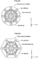
- Fig. 34 is a plan view of an ultrasonic transducer 100g in a ninth embodiment.
- This ultrasonic transducer 100g includes a circular diaphragm 5g, radial beams 7gr disposed radially on the top surface of the diaphragm 5g, and an annular beam 7gc disposed likewise.
- the diaphragm 5g may be in an ellipse shape.
- Fig. 35 is a plan view of an ultrasonic transducer 100h in a tenth embodiment.
- This ultrasonic transducer 100h includes a diaphragm 5h in a hexagonal shape, radial beams 7hr disposed radially on the top surface of the diaphragm 5h, and a cell shaped beam 7hc disposed along the inner margin of the diaphragm 5h likewise.
- the hexagonal shape is an example, and the shape of the diaphragm 5h may be a triangle, pentagon, heptagon, or another polygon.
- the above described radial beams 7gr are provided in a quantity of four (in eight directions from the center) in the ninth embodiment, and the above described radial beams 7hr are provided in a quantity of three (in six directions from the center) in the tenth embodiment.
- a suitable number of such beams may be provided, depending on the shapes of the diaphragms 5g and 5h, desired frequency spectrum and the like.
- the annular beam 7gc in the ninth embodiment and the cell shaped beam 7hc in the tenth embodiment are provided respectively in a single quantity, as examples.
- a suitable number of such beams may be provided, concentrically for example, depending on the shapes of the diaphragms 5g and 5h, desired frequency spectrum and the like.
- Fig. 36 is a plan view of an ultrasonic transducer 100i in an eleventh embodiment.
- This ultrasonic transducer 100i has a structure having plural beams 7 which are elongated in y direction and disposed at uneven intervals.
- the distribution of stiffness of the oscillating part 5c of a diaphragm 5 can be partially adjusted and an oscillation mode can be desirably inhibited or excited, by suitably setting the pitches of disposing the plural beams 7.
- Fig. 37 is a plan view of an ultrasonic transducer 100j, in a twelfth embodiment, for which the long axis directions of beams 7 are set to different directions.
- This ultrasonic transducer 100j has a structure having a beam 7x which is elongated in x direction and shorter in the long axis direction thereof than the length in x direction of an oscillating part 5c of a diaphragm 5, beams 7y which are elongated in y direction and shorter in the long axis direction thereof than the length in y direction of the oscillating part 5c of the diaphragm 5, the beams 7x and 7y being arranged on an outer diaphragm layer 5b.
- the beam 7x and 7y having different long axis directions may be disposed in mixture at different positions on the same diaphragm 5. Further, the beams 7x and 7y may have lengths shorter than the planar dimensions of the oscillating part 5c, depending on the purpose. Still further, the dimensions of the beams 7x and 7y may be different from each other.
- an oscillation mode/modes can be desirably inhibited or excited for each part of the oscillating part 5c, by suitably setting the positions, pitches, quantity of the beams 7y and 7x.
- Fig. 38 is a vertical cross-sectional view of an ultrasonic transducer 100k in a thirteenth embodiment.
- This ultrasonic transducer 100k has a structure having beams 7i, 7j and 7k which are elongated in y direction, have different cross-sections perpendicular to the long axis, and are disposed in mixture on a diaphragm 5.
- the beams 7i having the largest cross-section are disposed adjacent to the center of the diaphragm 5, the beams 7j having a smaller cross-section than the beams 7i are disposed outside the beams 7i, and the beams 7k having a smaller cross-section than the beams 7j are disposed outside the beams 7j.
- the stiffness of the portion in the vicinity of the center of the diaphragm 5 is greatly reinforced while the stiffness is less reinforced toward the marginal portion of the diaphragm 5. This disposition is an example and the order of disposing the beams 7i, 7j and 7k may be changed.
- the distribution of stiffness of the diaphragm 5 can be adjusted, and thereby, desired oscillation modes and resonance frequencies f b for the respective oscillation modes can be obtained.
- Fig. 39 is a plan view of an ultrasonic transducer 1001, in a fourteenth embodiment, provided with beams 7 of which long axes intersect with each other.
- This ultrasonic transducer 1001 has a structure having a beam 7q elongated in x direction (horizontal direction in the figure) and beams 7r elongated in y direction (vertical direction in the figure) on the top surface of an outer diaphragm layer 5b.
- the stiffness of the diaphragm 5 with respect to x direction can be changed by the horizontally elongated beam 7q
- the stiffness of the diaphragm 5 with respect to y direction can be changed by the vertically elongated beams 7r. Accordingly, even when the planar shape and dimensions of the oscillating part 5c of the diaphragm 5 are predetermined, it is possible to independently and arbitrarily set the resonance frequency f bx of an oscillation mode in x direction and the resonance frequency f by of an oscillation mode in y direction.
- the planar shape of the oscillating part 5c of the diaphragm 5 is substantially a square shape.
- the stiffness of this oscillating part 5c is reinforced by the single beam 7q elongated in x direction and the three beams 7r elongated in y direction.
- the oscillating part 5c of the diaphragm 5 has a small stiffness in x direction and a large stiffness in y direction despite the substantially square shape thereof.
- the beam 7q and each beam 7r may be joined with each other, or may intersect with each other in stories with respect to z direction (perpendicular direction to the sheet of the figure).
- the ultrasonic transducers 100, 100b to 1001 in the respective embodiments the following effects can be obtained, for example.
- Fig. 40 is a vertical cross-sectional view of an ultrasonic transducer lOOp of a Comparative Example.
- This ultrasonic transducer lOOp has the same structure as the ultrasonic transducer 100 (refer to Fig. 18 ) in the third embodiment except that no beam 7 is arranged.
- Fig. 41 is a diagram of a graph showing the frequency versus gain response of a diaphragm 5 in a rectangular planar shape with a ratio of longitudinal length to lateral length of 1:2.
- a notch (an area where gain G rapidly drops) appears near 0.8 MHz on the graph. Accordingly, there is a problem that the value of the frequency versus gain response of the diaphragm 5 is not flat. This notch is generated by the bonding between the lateral oscillation mode and the longitudinal oscillation mode. Therefore, it is understood that one of the oscillation modes can be inhibited and thereby notch is restricted by changing the longitudinal and/or lateral stiffness.
- the inventors produced design examples of the ultrasonic transducer 100 (refer to Fig. 18 ) in the third embodiment and the ultrasonic transducer lOOp of the comparative example, as described later. Design values were input in details to a computer, highly accurate numerical simulation was carried out regarding characteristic in water, and a result was compared with the calculation result described above (refer to Fig. 24 ).
- the substrate 1 is formed of silicon
- the diaphragm 5 is formed of silicon nitride
- the electrodes 2 and 3 are formed of aluminum.
- the vertical dimension (up-and-down direction, namely y direction, in Fig. 19 ) of the diaphragm 5 was set to 40 ⁇ m, and the length in the direction perpendicular to this direction on the same plate surface (left-right direction, namely x direction, in Fig. 19 ) was set approximately to 400 ⁇ m. These dimensions were set such as to make the vertical length/horizontal length ratio small enough, considering prevention of unnecessary oscillation modes from being excited. Further, the total thickness of the electrode 2 on the substrate 1 side and the substrate 1 is large enough for the displacement to be neglected substantially.
- the beams 7 of the ultrasonic transducer 100 are formed of the same material as the diaphragm 5.
- the width w of the beams 7 was set to 20 percent of the pitch between the beams 7.
- the resonance frequency f b of the diaphragm 5 in the third embodiment be the same as that of the diaphragm 5 in the comparative example and make the fractional bandwidth f h of the diaphragm 5 in the third embodiment is 1.5 times as wide as that in the comparative example, and based on the calculation result (refer to Fig.
- the diaphragm 5 of the ultrasonic transducer 100 was made 0.54 times as thick as the diaphragm 5 of the ultrasonic transducer lOOp of the comparative example, and the beams 7 were made 0.66 times as thick as this diaphragm 5 of the ultrasonic transducer 100p.
- the thicknesses of electrode 2, cavity 4 and electrode 3 were made the same as those of the ultrasonic transducer lOOp of the comparative example.
- the cavity 4 above the electrode 2 on the substrate 1 side was formed 300 nm thick, and the inner diaphragm layer 5a was formed 200 nm thick.
- the electrode 3 on the diaphragm 5 side was formed 400 nm thick, and the outer diaphragm layer 5b was formed 2000 nm thick.
- Fig. 42 is a diagram of graphs showing the frequency spectrums in water of the ultrasonic transducer 100 in the third embodiment and the ultrasonic transducer lOOp of the comparative example.
- a graph 31 represents measured values with the ultrasonic transducer 100 in the third embodiment, and a curve 30 represents measured values with the ultrasonic transducer lOOp of the comparative example.
- the center frequency f c was 15.4 MHz and the fractional bandwidth f h was 157% .
- the center frequency f c was 14.8 MHz and the fractional bandwidth f h was 120%.
- the ultrasonic transducer 100 in the third embodiment maintains the substantially same value of the center frequency f c , and shows a greater value of the fractional band width f h . This result agree with the tendency of the above described calculated result.
- the fractional bandwidth f h of the ultrasonic transducer 100 in accordance with the invention should be approximately 1.5 times as wide as the fractional bandwidth f h of the ultrasonic transducer lOOp of the comparative example.
- the ratio is approximately 1.3 times instead of 1.5 times. This is because, while the calculation result (refer to Fig. 24 ) is based on assumption that the respective elements are homogeneous, the numerical simulation (refer to Fig. 42 ) follows realistic element structures more faithfully wherein the diaphragm 5 includes the electrode 3 and others and is inhomogeneous accordingly.
Description
- The present invention relates to a diaphragm type ultrasonic transducer, ultrasonic probe, and ultrasonic imaging device.
- Mainstream transducers transmitting and receiving ultrasound transmit and receive ultrasound, using piezoelectric effect and inverse piezoelectric effect of a ceramic piezoelectric element represented by PZT (lead zirconate titanate). This type of piezoelectric ceramic ultrasonic transducer currently still constitutes the majority of ultrasonic transducers in practical use. However, to take the place of this type, research and development of diaphragm type fine ultrasonic transducers having a structure in micrometer order by a semiconductor micro processing technology has been carried out since the 1990's (refer to Non-patent Document 1).
- In a typical structure of such a transducer (an
ultrasonic transducer 100p) is, as shown in a cross-sectional schematic view inFig. 40 , a capacitor is formed by a bottom electrode 2 (which is an electrode on a substrate side and will be hereinafter also referred to also merely as an electrode 2) and a top electrode 3 (which is an electrode on anouter diaphragm layer 5b side and will be hereinafter also referred to merely as an electrode 3) which are provided respectively on asubstrate 1 and on a flatouter diaphragm layer 5b with acavity 4 therebetween. - Hereinafter, for brevity of description, the direction where the ultrasonic transducer lOOp receives ultrasound (downward direction in
Fig. 40 ) will be referred to as z direction, the right direction inFig. 40 will be referred to x direction, and the perpendicular downward direction with respect to the sheet ofFig. 40 will be referred to as y direction. - As shown in
Fig. 40 , when a voltage is applied between theelectrodes outer diaphragm layer 5b. In this situation, when the outer surface of theouter diaphragm layer 5b is in contact with water or an organism, sound waves are radiated into such medium. This is the principal of electro-acoustic (ultrasound) conversion in transmission. On the other hand, when a DC bias voltage is applied to induce a certain amount of charges on theelectrodes diaphragm layer 5b, thereby displacing thediaphragm layer 5b, then a voltage is additionally generated between theelectrodes - In order to form ultrasonic beams, a number of the above described transducers are disposed and arrayed, as shown in
Fig. 43 , to be used. InFig. 43 , plural hexagonalultrasonic transducers 100 are electrically connected byconnection 13 arranged between ultrasonic transducers to form a single channel partitioned by shown dashedlines 20. Ultrasonic pulses are transmitted and received, utilizing ultrasonic transducers. Herein, in imaging tomography of a subject from echo signals, the flatter the frequency spectrum of the electro-mechanical conversion efficiency of the ultrasonic transducers, the narrower the pulse width with respect to the time axis, achieving higher resolution. Further, the degree of freedom in controlling a device is advantageously increased, an example of which is that different frequencies can be selected, depending on the distance from an ultrasonic transducer to a subject. Therefore, a method is disclosed, inPatent Document 1, to achieve a broadband by simultaneously drivingultrasonic transducers 100, as shown inFig. 44 , having respective diaphragms in different diameters, the ultrasonic transducers being connected by connections therebetween to serve as asingle element 14. - Further,
Patent Document 2 discloses a capacitive ultrasonic transducer reinforced by a stiffing layer at the central portion of a film. - Still further,
Patent Document 3 discloses an acoustic transducer with a structure, arranged above a cavity, having an insulating layer part and a top electrode which are disposed within the thickness dimension of a film. - Non-patent Document 1: " A surface micromachined electrostatic ultrasonic air transducer", Proceedings of 1994 IEEE Ultrasonics Symposium, pp. 1241-1244
- Patent document 1: the specification of United States Patent No.
5,870,351 - Patent document 2: the specification of United States Patent No.
6, 426, 582 - Patent document 3: the specification of United States Patent No.
6,271,620 - Further,
US 2004/190377 A1 discloses an ultrasonic transducer with the features in the pre-characterizing portion ofClaim 1.JP 2005 110204 A - However, in the technology disclosed in
Patent Document 1, as shown inFig. 44 , an ultrasonic probe configured with diaphragms in polygonal or circular shapes in different sizes packed in an area inevitably has gaps between ultrasonic transducers. These gaps make a problem of deteriorating the performance of the ultrasonic probe due to the following two causes. First, a decrease in the effective element area drops the effective sensitivity for transmission and reception of waves. Second, if a portion of the element, the portion being provided with no diaphragm, is exposed in the aperture, of the ultrasonic probe, for transmission and reception of waves, a sound having entered through the portion into the substrate causes a reverberant sound and a false image on a diagnosis image. Reverberant sound may also be caused by the phenomenon that an ultrasound from a diaphragm passes through a portion not formed with a diaphragm, and this propagated ultrasound is reflected by the edge of an adjacent ultrasonic transducer, and finally returns to the original diaphragm. - Further, regarding transducer arrays, in general, the upper limits of the sizes of respective ultrasonic transducers are defined by the disposition pitch for which diffraction of ultrasound and the like is taken into account, and the lower limits of the sizes are defined from a point of view of securing radiation impedance which achieves a required radiation efficiency. Therefore, the sizes of these ultrasonic transducers are selected usually from a narrow range in designing.
- Still further, since a semiconductor manufacturing technology is used for the above described conventional electrostatic transducer (described in Non-patent Document 1), masks corresponding to the planar shapes of diaphragms are used in a manufacturing process. There is a method of changing the frequency spectrum of a diaphragm, which changes the size (planar shape) of the diaphragm. However, it is necessary to design and manufacture a new mask for this method, which requires time and cost, causing a problem of decreasing the manufacturing efficiency.
- Yet further, another method of changing the frequency spectrum of a diaphragm changes the thickness of the diaphragm. However, as described above, as the size of a diaphragm is limited in a narrow range, the thickness of the diaphragm which achieves a desired center frequency is substantially uniquely determined. Then, the size and thickness of the diaphragm define the sensitivity and fractional bandwidth of this ultrasonic transducer. Consequently, there has been a problem that a desired frequency spectrum, namely, a combination of a center frequency and a fractional band width cannot be realized.
- Further, for the above described conventional capacitive ultrasonic transducer (refer to Patent Document 2), a diaphragm is reinforced by a stiffing layer. However, even obtaining a desired center frequency by arranging a stiffing layer, there has been a problem that the fractional bandwidth is automatically defined and a desired frequency spectrum cannot be achieved.
- Still further, for the above described conventional acoustic transducer (described in Patent Document 3), a top electrode is arranged inside a diaphragm. Consequently, although the sensitivity may be improved, there has been a problem that means for obtaining a desired frequency spectrum is not provided, either.
- Addressing problems, as described above, an object of the present invention is to provide an ultrasonic transducer, ultrasonic probe, and ultrasonic imaging device having a simple structure and being capable of improving the performance of transmission and reception of ultrasound.
- The ultrasonic transducer of the present invention is defined in
Claim 1. Further advantageous features are set out in the dependent claims. - According to the present invention, an ultrasonic probe is provided which have a simple structure and are capable of improving the performance of transmission and reception of ultrasound are provided.
-
-
Fig. 1 is a diagram showing an example of a structure of an ultrasonic imaging device in a first embodiment which is not an embodiment of the invention but an example useful for its understanding; -
Fig. 2 is a diagram illustrating the relationship between the distance between diaphragms and a pulse waveform; -
Fig. 3 is a diagram illustrating the relationship between the distance between diaphragms and a reflected waveform; -
Fig. 4 is a diagram illustrating the distance between diaphragms and the intensity of a reflected waveform; -
Fig. 5 is a plan view showing an ultrasonic probe in the first embodiment; -
Fig. 6 is a diagram showing a structure of a semiconductor diaphragm type ultrasonic transducer in the first embodiment; -
Fig. 7 is a top view of the semiconductor diaphragm type ultrasonic transducers in the first embodiment; -
Fig. 8 is a top view of the semiconductor diaphragm type ultrasonic transducers in the first embodiment; -
Fig. 9 is a diagram illustrating utilization of a broaden frequency band; -
Fig. 10 is a diagram showing ultrasonic transducers to be used, switching the width/widths of a single electrical element/elements, depending on the mode; -
Fig. 11 is a diagram illustrating the effect of switching a manner of bundling a sub-element, corresponding to the distance to a focal point; -
Fig. 12 is a diagram illustrating a sub-element cross point switch and the periphery; -
Fig. 13 is a top view of a transducer array in the first embodiment; -
Fig. 14 is a schematic cross-sectional view of a semiconductor diaphragm type ultrasonic transducer in the first embodiment; -
Fig. 15 is a top view of a transducer array to be used, switching the width/widths of a single electrical element/elements, depending on the mode; -
Fig. 16 is a top view of an ultrasonic transducer in a second embodiment which is not an embodiment of the invention but an example useful for its understanding; -
Fig. 17 is a schematic cross-sectional view of the ultrasonic transducer in the second embodiment; -
Fig. 18 is a vertical cross-sectional view showing an ultrasonic transducer in a third embodiment as an embodiment of the invention; -
Fig. 19 is a plan view showing the ultrasonic transducer in the third embodiment; -
Fig. 20 is a perspective view of a transducer array; -
Fig. 21 is a diagram of a graph showing an example of the frequency versus gain response of an ultrasonic transducer; -
Fig. 22 is a schematic view showing a bending state of a beam; -
Fig. 23 is a schematic perspective view of an oscillating body in accordance with the invention and an oscillating body of a comparative example; -
Fig. 24 is diagram of graphs showing a result of calculation of resonance frequency and fractional bandwidth in a case where the width of a beam of an oscillating body is set to 20 percent of the width of a base plate; -
Fig. 25 is a diagram of graphs showing a result of calculation of resonance frequency and fractional bandwidth in a case where the width of a beam of an oscillating body is set to 80 percent of the width of a base plate; -
Fig. 26 is a schematic perspective view of a beam of a modified example; -
Fig. 27 is a schematic perspective view of beam shapes of other modified examples; -
Fig. 28 is a vertical cross-sectional view of an ultrasonic transducer in a fourth embodiment as an embodiment of the invention; -
Fig. 29 is a vertical cross-sectional view of an ultrasonic transducer in a fifth embodiment which is not an embodiment of the invention but an example useful for its understanding; -
Fig. 30 is a vertical cross-sectional view of an ultrasonic transducer in a sixth embodiment as an embodiment of the invention; -
Fig. 31 is a vertical cross-sectional view of an ultrasonic transducer in a seventh embodiment which is not an embodiment of the invention but an example useful for its understanding; -
Fig. 32 is a vertical cross-sectional view schematically showing the movement of the ultrasonic transducer in the seventh embodiment; -
Fig. 33 is a plan view of an outer diaphragm layer in an eighth embodiment as an embodiment of the invention; -
Fig. 34 is a plan view of an ultrasonic transducer in a ninth embodiment which is not an embodiment of the invention but an example useful for its understanding; -
Fig. 35 is a plan view of an ultrasonic transducer in a tenth embodiment which is not an embodiment of the invention but an example useful for its understanding; -
Fig. 36 is a plan view of an ultrasonic transducer in an eleventh embodiment which is not an embodiment of the invention but an example useful for its understanding; -
Fig. 37 is a plan view of an ultrasonic transducer in a twelfth embodiment which is not an embodiment of the invention but an example useful for its understanding; -
Fig. 38 is a vertical cross-sectional view of an ultrasonic transducer in a thirteenth embodiment which is not an embodiment of the invention but an example useful for its understanding; -
Fig. 39 is a plan view of an ultrasonic transducer in a fourteenth embodiment which is not an embodiment of the invention but an example useful for its understanding; -
Fig. 40 is a vertical cross-sectional view of an ultrasonic transducer of a comparative example (conventional example); -
Fig. 41 is a diagram of a graph showing the frequency versus gain response of a diaphragm in a rectangular planar shape with a ratio of longitudinal length to lateral length of 1:2; -
Fig. 42 is a diagram of graphs showing the frequency spectrums in water of theultrasonic transducer 100 in the third embodiment and the ultrasonic transducer lOOp of the comparative example; -
Fig. 43 is a top view of a transducer array; -
Fig. 44 is a diagram illustrating an ultrasonic transducer in which diaphragms with different diameters are disposed; -
Fig. 45 is a diagram illustrating the path of an ultrasound reflecting between diaphragms; and -
Fig. 46 is a diaphragm illustrating noise generation due to ultrasound having entered a substrate through gaps between diaphragms. -
- 1
- substrate
- 2,3
- electrode
- 4
- cavity
- 5
- diaphragm
- 7
- beam
- 13
- connection
- 14
- element
- 17
- switch
- 100
- ultrasonic transducer
- 1000
- transducer array
- Now, embodiments in accordance with the present invention as well as examples useful for its understanding will be described in details, referring to
Figs. 1 to 42 andFigs. 44 to 46 . - Hereinafter, "a converter between electricity and ultrasound" will be referred to as "an ultrasonic transducer", "a group of plural ultrasonic transducers in an array" as "a transducer array", and "a member that has plural transducer arrays and transmits and receives ultrasounds to and from a specimen" as "an ultrasonic probe". Further, "an ultrasonic imaging device" will represent "an imaging device by the use of ultrasound provided with an ultrasonic probe, image former (means for forming an image from a signal obtained by an ultrasonic probe), display (means for displaying an image), controller, and the like".
-
Fig. 1 is a diagram showing an example of a structure of an ultrasonic imaging device using ultrasonic transducers in a first embodiment. Referring toFig. 1 , the operation of the ultrasonic imaging device will be described. - Based on control by a transmission/
reception sequence controller 201 programmed in advance, a transmission delay andweight selector 203 selects the values of a transmission delay time and a weight function for each channel to be supplied to a transmission beam-former 204. According to these values, the transmission beam-former 204 supplies an electro-acoustic conversion element 101 with transmission pulses throughplural switches 205 for switching transmission/reception waves. Herein, an electro-acoustic conversion element 101 is also applied with a bias voltage by abias voltage controller 202. As a result, the electro-acoustic conversion element 101 transmits ultrasound to a specimen, not shown here. - Then, the ultrasounds having been reflected by scatterers in the specimen and thereby reflected are partially received back by the electro-
acoustic conversion element 101. A transmission/reception sequence controller 201 then controls a reception beam-former 206 after a predetermined time has elapsed from the timing of transmission so as to start a reception mode. The predetermined time described above, in a case of obtaining an image from a depth of a specimen deeper than 1 mm for example, is the turn around time for a sound to return a distance of 1 mm. The mode does not change to the reception mode immediately after transmission because the amplitude of the reception voltage is extremely smaller than the amplitude of the transmission voltage, being one hundredth to one thousandth. The reception beam-former 206 continuously controls the delay time and a weight function, corresponding to the arrival time of each reflected ultrasound, which is so-called a dynamic focus. Data after dynamic focus is converted into an image signal by image forming means including, for example, afilter 207,envelope detector 208, andscan converter 209, and then displayed on adisplay 210 as an ultrasonic tomographic image. - One of the basic characteristics which are significant in putting ultrasonic transducers in various practical uses is frequency spectrum represented by a center frequency and a fractional bandwidth. A center frequency fc is a frequency with the highest electromechanical conversion efficiency (sensitivity) . A fractional bandwidth fh is, for example in a case of 3dB width, defined as a difference between two frequencies divided by the center frequency, wherein the sensitivity at these two frequencies is 3 dB lower than the sensitivity at the center frequency. If the fractional bandwidth is wider, a single ultrasonic transducer can be used for more various frequency bands, or ultrasonic pulses with a shorter time width can be formed, which achieves advantageous characteristics, such as obtaining a high distance resolution in a case of imaging by the use of ultrasonic beams. The center frequency fc of a diaphragm type ultrasonic transducer is substantially equal to the value of resonance frequency of the diaphragm, and is accordingly represented by following Expression (1), while the fractional bandwidth fh is represented by Expression (2), wherein the stiffness and the mass of the diaphragm are represented respectively by D and m.


- The stiffness and mass of an oscillation diaphragm are determined by the shape and dimensions of the oscillation diaphragm and the thickness thereof in a case of a solid material. Accordingly, in principle, by defining a proper shape and thickness of an oscillation diaphragm, a desired frequency spectrum can be obtained. However, only the two-degree-of-freedom of D and m for designing is not enough to optimize the three parameters of the center frequency, maximum value of sensitivity and fractional bandwidth.
- An ultrasonic probe for an ultrasonic imaging device for photographing common two-dimensional tomographic images performs fixed focusing by an acoustic lens in the direction (short axis direction) perpendicular to the tomographic plane, and performs electronic focusing of an ultrasonic beam at a desired position on the tomographic plane, having arrayed oscillators arranged in the direction (long axis direction) along the tomographic plane. In order to form excellent ultrasonic beams, ultrasonic transducers are arrayed ideally with a width of approximately a half of the wavelength at the center frequency of beams. For example, with a center frequency of 5 MHz, ultrasonic transducers are arrayed with a width of approximately 0.15 mm. In the short axis direction, the wider the width of an ultrasonic transducer is, the narrower the beam width at the focus is, achieving a tomographic image with a higher space resolution. However, if the focus region of the fixed focus on the short axis is too narrow, it is difficult to control the focus region by electronic focusing on the long axis. Further, also in viewpoint of usability in operation by pressing the ultrasonic probe on an affected area, such as a gap between costae of a patient, the width along the short axis is preferably 7 to 8 mm.
- That is, since the size of an electric element is approximately 7 to 8 mm x 0.15 mm, in a case where the diameter of a diaphragm is approximately 50 µm for example, 450 (150 x 3 = 450) diaphragms are used in a state of being disposed in a single electric element. By changing the shape and material of each of the several hundred diaphragms, the fractional bandwidth of the entire single electric element can be designed more freely. There is a degree of freedom for the shape and material in principle. However, in a practical semiconductor process, a layer structure is formed on a substrate, layer by layer, it is not realistic to change the material for each transducer adjacent to one another, and it is also difficult to change the thickness of diaphragms. As a result, designing a desired fractional bandwidth by changing the diameters of diaphragms is the most practical method.
- In the specification of United States Patent No.
5, 870, 351 (Patent Document 1), an example, as shown inFig. 44 , is disclosed where a number of hexagonal shapes of diaphragms with different diameters are disposed in a single element which are electrically connected. However, when circles or polygonal shapes with different diameters are packed in an area, there arises a problem that the packing efficiency drops. To be more significant than the problem of drop in the sensitivity due to the drop in the ratio of "diaphragm area/entire element area", the pulse response of the element is greatly affected. This deterioration of pulse response will be described, referring toFig. 45 . As shown inFig. 45 , when plural diaphragms in hexagonal shapes in different sizes are disposed, the total length of a path (arrow in the figure) on which an ultrasonic wave passes from one diaphragm through spaces where no diaphragm is formed, gets reflected by the surfaces of diaphragms adjacent to the one diaphragm, and returns to the one diaphragm is longer than in a case where hexagonal diaphragms with the same diameter are packed to form an array. -
Fig. 2 is a diagram of graphs showing a result of a simulation of a received ultrasonic pulse response by finite element method in a case of changing the distance between one diaphragm and adjacent diaphragms. Herein, as an example, a two dimensional model with diaphragms with a width of 60 µm and an unlimited length is employed. The material of the diaphragms is silicon nitride (SiN), and the thickness is 1.2 µm. Ultrasonic waves arriving from the front face of the array are sine waves with a center frequency of 10 MHz, and a cycle number of one periodic time. The horizontal axis represents time with an origin being the time when an ultrasonic pulse arriving from the front face of the array arrives at the surface of a diaphragm. The vertical axis represents the vertical velocity of the central portion of the diaphragm. The four graphs show the cases where the distance between adjacent diaphragms are 5 µm, 20 µm, 40 µm and 60 µm. - From
Fig. 2 , it is understood that the wider the distance between adjacent diaphragms, the wider the pulse width. When the distance between adjacent diaphragms is 5 µm, the diaphragm is deformed substantially the same as the waveform of an ultrasonic wave arriving from outside; the central portion of the diaphragm oscillates in a sine wave for one periodic time; thereafter (approximately 0.1 µ sec later), the oscillation amplitude rapidly becomes small; the pulse width is narrow; and the frequency spectrum of the transmission function converting the ultrasonic wave to the deformation of the diaphragm is substantially flat. On the other hand, the wider the distance between the adjacent diaphragms is, the more the pulse waveform is extended. When the distance between adjacent diaphragms is 60 µm, the pulse width is extended substantially 1.5 times compared with the case of the distance between adjacent diaphragms of 5 µm, showing that using an array in such conditions deteriorates the space resolution. -
Fig. 3 is a diagram of graphs showing waveforms of reception pulses in cases with the distance between adjacent diaphragms of 20 µm, 40 µm, and 60 µm, subtracted by a waveform of a reception pulse in a case of the distance between adjacent diaphragms of 5 µm. By comparing with the waveform of the reception wave with the distance between adjacent diaphragms of 5 µm, which is almost free from affect by reflected waves form adjacent diaphragms, reflected waves from the adjacent diaphragms can be extracted. It is apparently shown that the reflected waves from the adjacent diaphragms become larger, corresponding to the distance between the adjacent diaphragms. - The integrated values of the amplitudes of the reflected waves are represented by the vertical axis, and the distances between adjacent diaphragms are represented by the horizontal axis, in the graph in
Fig. 4 . The vertical axis is normalized by the integrated value of the amplitude of the original reception waveform. It is shown that the value of the vertical axis becomes 0.1 or smaller where affects by a reflected wave can be almost neglected, when the distance between adjacent diaphragms is 10 µm or smaller. Taking into account that the acoustic velocity propagating in silicon material is 8000 m/s, this means that the distances between adjacent diaphragms is 1/80 of the wavelength or shorter because the wave length of an ultrasonic wave at 10 MHz is 800 µm. - In the ultrasonic transducer region as one element configured by electrically connecting diaphragm type plural ultrasonic transducers, if there is a region in which diaphragms are not formed, the pulse response is deteriorated also in the process described below.
Fig. 46(a) and 46(b) illustrate the mechanism in which an ultrasonic wave entering a substrate from a gap between diaphragms generates a noise.Fig. 46(a) is a schematic cross-sectional view of a diaphragm and the peripheral, andFig. 46 (b) is a diagram showing the temporal change in a gain voltage signal. - As shown
Fig. 46 (a) , regarding a case of receiving an ultrasonic pulse coming from above a diaphragm, an ultrasonic pulse A having directly entered a diaphragm is first converted into an electrical signal, as shown as A in the graph with the horizontal axis of time and the vertical axis of echo voltage signal inFig. 46(b) . On the other hand, an ultrasonic pulse B having arrived in a region of a gap between diaphragms, as shown by paths a, b and c inFig. 46 (a) , repeats multiple reflections in the substrate, passes through a limb portion of a diaphragm, and arrives at the diaphragm. The ultrasonic pulse having passed through the paths a, b and c is also converted into an electric signal by deforming the diaphragm, and appears as an electric signal with waveforms B, B' and B" as shown inFig. 46(b) . - With an ultrasonic imaging device, in a case, for example, of observing the inner structure of a blood vessel, in order to observe sites of which reflectance intensities differ from each other by 40 dB to 60 dB, such as the tissue site of the blood vessel and the lumen of the blood vessel, an image of the structure is created by compressing the brightness and with a wide dynamic range. Therefore, even if the echo of B and B' are imperceptible, when echo of delayed B and B' accompanies the reflectance signal A from the tissue site of the blood vessel, the echo is observed as an image inside the blood vessel, which does not allow distinction between a plaque in the blood vessel and a false image of B or the like. Judging from the dynamic range of an image by a common ultrasonic imaging device, the amplitude of a reflectance signal B is necessary to be reduced to one thousandth, namely approximately -60 dB, compared with the amplitude of a reflectance signal A. As described above, by shortening the gap between diaphragms approximately to one eightieth of a wave length, the transmission efficiency of a sound through the gap drops and effect by a reverberant sound, such as B, does not become a problem. By making the amplitude of an ultrasound entering a wafer along the path "a" small enough, the reverberant sound of B becomes small even if the reflectance ratio of the multiple reflections along the path b cannot be made small enough. As a result, it is possible to increase the degree of freedom in selection of the thicknesses and material of the adhesive to be applied to a wafer and a backside material having significant effects on the reflectance ratio of the multiple reflections along the path b, thereby improving the degree of freedom of manufacturing process.
- In the present embodiment, the shapes and structures of diaphragms are adopted which are suitable for making the resonance frequencies differ from each other to widen the fractional bandwidth, while minimizing the areas of gaps between diaphragms.
-
Fig. 5 shows an example of an ultrasonic probe in the present embodiment, and is a top view showing a part of a semiconductor diaphragm type transducer array configuring the ultrasonic probe.Fig. 6 is a schematic diagram showing an oblique top view of one of the diaphragm type ultrasonic transducers in the array shown inFig. 5 , the one being cut for viewing. - Each diaphragm type ultrasonic transducer is, as shown in
Fig. 6 , includes a bottom electrode 2 (the first electrode) formed on asubstrate 1, aninner diaphragm layer 5a being formed on thebottom electrode 2 and having acavity 4 therein, a top electrode 3 (the second electrode) provided on theinner diaphragm layer 5a, and anouter diaphragm layer 5b, which are disposed in this order, and abeam 7 connecting opposite apexes of the diaphragm, the beam being formed on theouter diaphragm layer 5b. Thebottom electrode 2 and thetop electrode 3 are facing each other through theinner diaphragm layer 5a having thecavity 4 therein, and configure a capacitor. At the central portion of each diaphragm in a hexagonal shape, a film in a homothetic shape of the diaphragm is formed to be continuous with thebeam 7. - Hereinafter, both or either the
inner diaphragm layer 5a or theouter diaphragm layer 5b may be described merely as "diaphragm" . Further, symbols of other elements may be omitted. - As shown in
Fig. 7 , ifbeams 7 only are formed, acute angles are formed in a part wherebeams 7 near the central part of a diaphragm intersect each other, which may cause variation in trimming the acute angle portion by etching process of semiconductor or the like. Herein, forming a homothetic shape portion at the center brings an advantage of not forming an acute angle portion. Further, in a diaphragm type ultrasonic transducer, applying a high DC bias improves the sensitivity of transmission and reception because more charges are accumulated. However, if an excessive DC bias is applied, a part of the diaphragm comes in contact with the opposite surface of thecavity 4. Such a contact causes charge emission into the diaphragm, and drifts the electro-acoustic conversion characteristics of the element. In a case of formingbeams 7, the contact starts at the gaps between thebeams 7 and a portion adjacent to the center of the diaphragm. In order to increase the upper limit of the DC bias which can be applied causing no contact, since deformation without unflatness is advantageous, it is advantageous to form a film in a homothetic shape of the diaphragm in the vicinity of the intersection between thebeams 7. Herein, if the homothetic shape is too large, the gaps between thebeams 7 are all filled to lose the effect of forming thebeams 7. Accordingly, the diameter of the homothetic shape is preferably approximately 50% to 80% of the diameter of the entire diaphragm. - Herein, the
beams 7 have a structure having a smaller width compared with the length and a shape covering only a part of the diaphragm. Thebeams 7 effect the resonance frequency of the diaphragm type entire ultrasonic transducer, by having the hardness conditions described below. That is, the hardness of thebeams 7 is made great enough compared with the hardness of the material of the diaphragm portion forming the upper wall of thecavity 4, or the thickness of thebeams 7 is made great enough compared with the thickness of the diaphragm portion. Thus, the resonance frequency of the diaphragm type entire ultrasonic transducer can be controlled by the shape and material of thebeam 7. For example, withbeams 7 in a simple rectangular solid shape of a width W,length 1 and thickness t, the resonance frequency fb in the thickness direction is represented by the following Expression (3). Herein, E denotes Young's Module, I denotes the cross-sectional moment, and m denotes the mass.
- A
beam 7 with a cross-section in a rectangle shape has a cross-sectional moment I of Wt3/3, and accordingly Equation (3) is equivalent to Equation (4). As Equation (4) is a proportional expression, coefficients are omitted.
- Accordingly, if the materials of
beams 7 are the same and the thickness t andlength 1 are constant, the resonance frequency fb is proportional to the square root of the width W. - If the
beams 7 are in a rectangular solid shape with a width of W at the marginal portion, and are in a homothetic shape of the diaphragm, as shown inFigs. 5 and6 , at the central portion of the diaphragm, assuming that the central portion of the diaphragm to be approximately a spindle with a mass of M, Expression (3) is described as Expression (5), and almost the same case as described above is applicable.
- If the resonance frequency of a diaphragm can be controlled by the width W of
beams 7 in such a manner, then, by packing ultrasonic transducers having diaphragms with a constant diameter and beams 7 with different widths W provided on the front surfaces or back surfaces of the respective diaphragms, as shown inFig. 5 , it is possible to configure a single ultrasonic transducer with diaphragm type plural ultrasonic transducers with different resonance frequencies, without gaps between the diaphragms. InFig. 5 , the boundary of an ultrasonic transducer that functions as a single element is shown by dashedlines 20. Herein, thebottom electrode 2 is common to the diaphragm type plural ultrasonic transducers configuring the single ultrasonic transducer, and the top electrodes of the diaphragm type plural ultrasonic transducers configuring the single ultrasonic transducer are electrically connected mutually byconnections 13. - An example including materials and dimensions configuring the diaphragm type ultrasonic transducer, shown in
Fig. 6 , will be described below. Asubstrate 1 is made of silicon and abottom electrode 2 with a thickness of approximately 500 nm and made of metal or polysilicon is formed on the silicon substrate. On thebottom electrode 2, an insulation film of silicon oxide or the like is formed with a thickness of approximately 50 nm on which acavity 4 with a dimension in the thickness direction of approximately 200 nm is formed. An insulation film (the first diaphragm) 5 is formed with a thickness of approximately 100 nm to form the upper wall of thecavity 4, and atop electrode 3 is formed with a thickness of approximately 400 nm of metal such as aluminum on theinsulation film 5. On thetop electrode 3, formed is anouter diaphragm layer 5b with a thickness of approximately 200 nm of silicon nitride to cover theentire cavity 4, and further on theouter diaphragm layer 5b, formed is a film of silicon nitride with a thickness of approximately 1000 nm to form beams 7. - However, these materials and dimensions are only an example, and materials and dimensions may not be as described above. For example, assuming that the
beams 7 are made of silicon nitride, the diameter of the diaphragm is 60 µm, the thickness of the film is 2 µm, and the thickness of thebeams 7 is 4 µm, then, the center frequency is 7.8 MHz and -6 dB fractional bandwidth is 120% (-6 dB fractional band is 3 to 12.5 MHz) with W1 of 0.5 µm, the center frequency is 10 MHz and -6 dB fractional bandwidth is 100% (-6 dB fractional band is 5 to 15 MHz) with W2 of 4 µm, and the center frequency is 11.5 MHz and -6 dB fractional bandwidth is 96% (-6 dB fractional band is 6 to 17 MHz) with W3 of 20 µm. By optimizing the number of ultrasonic transducers having the beam width of W1, W2 and W3 (When the numbers of ultrasonic transducers having the beam width of W1 and W3 are greater than the number of ultrasonic transducers having the beam width of W2, a flatter frequency spectrum can be obtained.), -6 dB band becomes 3 to 17 MHz, that is, -6 dB fractional bandwidth becomes 140%. Compared with a known diaphragm structure with which -6 dB fractional bandwidth is approximately 100 to 120%, -6 dB fractional bandwidth is improved by 40 to 20 points. - In the example shown in
Fig. 5 , a film in a homothetic shape of the diaphragm in a polygonal shape is formed at the central portion of the diaphragm continuously with thebeams 7. However, even arrangingbeams 7, as shown inFig. 7 , without a film in a homothetic shape of the diaphragm at the central portion, the same effect can be obtained of course. On the other hand, as shown inFig. 8 , it is also possible to set different resonance frequencies of individual diaphragms by providinghard regions 15 in the respective central portions of the diaphragms and changing the sizes of thehard regions 15, without changing the size of the entire diaphragms. However, although the resonance of a diaphragm can be understood by breaking down into respective spring contributions defined by mass, structure and material, when a diaphragm is thick, contribution by the material and shape at a lib portion of the diaphragm is dominating with respect to the strength of the spring. Accordingly, in the case of the shape shown inFig. 8 , it is difficult to set different frequencies for individual diaphragms. Therefore, compared with a structure in whichhard regions 15 in different sizes are formed at the respective centers of diaphragms as shown inFig. 8 , preferable is a structure in which beams 7 having different widths and connecting opposite apexes of diaphragms in a polygonal shape are formed on the front surfaces or back surfaces of diaphragms, as shown inFig. 5 andFig. 7 . - Next, a method of utilizing the wide band characteristics of an ultrasonic probe in accordance with the invention will be described.
Fig. 9(a) is an illustration on how to select frequencies for respective observation sites, in a case of using a conventional probe with a fractional bandwidth of approximately 60%. In general, the higher the frequency is, the shorter the wavelength is, improving the space resolution. However, attenuation accompanying propagation of an ultrasound becomes greater substantially proportionally to the frequency. Therefore, in a case of observing with high penetration into a specimen, almost no signal returns due to attenuation. Thus, deterioration of signal/noise ratio due to attenuation and space resolution are in a trade-off relationship, and therefore, a frequency as high as possible is selected within a range satisfying a desired signal/noise ratio. Accordingly, depending on the depth of an observation object, an optimum frequency is substantially automatically determined, wherein selected are frequencies of approximately 2 MHz for observation at a depth of 15 to 20 cm from a body surface (such as a liver), approximately 10 MHz for observation at a depth of several centimeters from the body surface (such as a thyroid), and higher for a case such as a probe in a blood vessel. - Conventionally, as there has not been an ultrasonic probe that covers such a wide range of frequencies approximately from 2 MHz to 15 MHz, probes have been used for each of which a predetermined center frequency is set, optimizing each probe for a corresponding object site. Accordingly, a constant width among elements has been applicable, and arrays of elements of a fixed element width, such as to be a half to 75% of a wavelength, have been adopted. However, according to the invention, as shown in
Fig. 9(b) , a single probe can cover almost a frequency band necessary for an object of a human body. The symbols f1, f2 and f3 inFig. 9(b) represent drive frequencies in respective modes. - Herein, in order to operate a single probe with greatly different center frequencies by switching the drive frequency depending on the depth of the object site from the body surface, the element width is necessary to be switchable. Switching of the element width is determined when an object site is selected. In a case, the element width is constant in a single imaging plane. In another case, the object site is relatively large and the element width is necessary to be changed even in a single screen depending on the place to set the object site. In still another case, the object site is extending from a vicinity of the body surface to a deep portion and the element width is necessary to be switched accompanying the movement of the focus position while receiving ultrasound. For example, a case of switching the element width while receiving ultrasound will be described, referring to a device diagram. An ultrasonic pulse in a wide band is applied from a transmission beam-former 204 in
Fig. 1 through aswitch 205 and sub-elementcross point switch 17 to an ultrasonic probe configured with sub-elements 16, and the ultrasonic pulse is transmitted to a specimen not shown. - In the transmission beam-former 204, improving signal/noise ratio by widely transmitting ultrasonic pulses is more important than increasing the space resolution by narrowing the beam. Therefore, the number of sub-elements per channel is set small, and the total aperture is set narrow. Since ultrasounds scattered in a specimen return in order of nearness to the surface of the specimen, ultrasounds return in ascending order of the propagation distance in the specimen. In a conventional technology, ultrasounds returning from the specimen are received by reception beam-former 206 through the
switch 205; the delay time and weight coefficient are adjusted between channels; and a tomographic image is displayed through an envelope detector and a scan converter. On the other hand, in the invention, in a sub-elementcross point switch 17 between the sub-elements 16 and theswitch 205, when ultrasounds from near-surface portions are received, sub-elements are bundled in the quantity corresponding to the upper end of the band having transmitted the ultrasounds, and when ultrasounds from deeper portions are received, sub-elements are bundled in the quantity corresponding to the lower end of the band having transmitted the ultrasounds. The time is continuous from when ultrasounds are received from the near-surface portions until when ultrasounds are received from deeper portions, and accordingly, switching of the quantity of sub-elements is necessary to be carried out continuously in terms of time. - In the example in
Fig. 5 , diaphragms in a hexagonal shape are connected criss-crossingly to form an ultrasonic transducer of a single electrical element. However, in order to realize the above described mode, as shown inFig. 10 , by connecting plural ultrasonic transducers byconnections 13 only in the short axis direction, having the electrically connected ultrasonic transducers be a sub-element, and changing the quantity of sub-elements to be bundled in the long axis direction (array direction), the element width can be changed corresponding to the mode. Herein, the mode is imaging conditions automatically determined by the depth of the object site. The photograhing conditions include the drive frequency, cut-off value of the frequency filter for reception, the number of transmission sine waves, temporal weight function, aperture weight function, and the like. - When an operator of the ultrasonic transducer selects or inputs an object site, the range of the depth of imaging is usually determined, and the degree of attenuation of propagation medium can be estimated. Accordingly, various conditions, such as an optimum frequency, are determined. In a case, for example, of observing a relatively large body organ, such as liver or heart, the object site often extends from a near portion to a far portion even if the object site is determined. Therefore, in some cases, plural modes are applied even for a single object site, and the modes are automatically switched depending on the depth generated by a reflected echo. Sub-elements are configured by a group of diaphragm type ultrasonic transducers of which top electrodes are permanently connected by conductors. When a sub-element configures one element for beam forming, the sub-element serves as a unit of ultrasonic transducer bundled by a switchable switch. In
Fig. 10 , dashedlines 20 show the boundaries between sub-elements of ultrasonic transducers which are electrically connected. InFig. 10 , foursub-elements 16a to 16d are shown which are electrically connected in a direction perpendicular to the array direction. - For example, when a diameter of diaphragms which configure a single diaphragm type ultrasound transducer is 50 µm, although it is of course impossible to adjust the element width to a range narrower than the width of one diaphragm, an element width of 0.55 mm being 75% of a wavelength at 2 MHz can be achieved by 11 rows of diaphragms with a diameter of 50 µm, and the element width of 55 µm being 75% of a wavelength at 20 MHz can be achieved by one row of diaphragms with a diameter of 50 µm, which achieves an optimal element pitch for each mode in the range from 2 MHz to 20 MHz. That is, in this case, when driving an ultrasonic probe at 2 MHz, an element width of 0.55 mm can be attained by simultaneously driving eleven bundled adjacent sub-elements as one element, and when driving an ultrasonic probe at 20 MHz, an element width of 55 µm can be attained by driving individual sub-elements independently.
-
Fig. 11 is a diagram specifically illustrating how to change the number of sub-elements to be bundled and an effect of it.Fig. 11(a) shows the state where the focus of a transmission wave or reception wave is set to the nearest distance Fn. In this case, since each element is arranged in such a manner that a single sub-element with a width of Ws forms one element, the total aperture width Wn = Ws x N for a system with the number of channels N. On the other hand,Fig. 11b shows a state where the focus is set to a deeper distance Ff. In this case, since an element with a width of Wc is structured by bundling two sub-elements, the total aperture width Wf = Wc x N = 2 x Ws x N. For a still deeper focus, the total aperture width can be widened by increasing the number of sub-elements to be bundled. In this way, even changing the focus of the ultrasonic probe, F value, in other words, focal length/ aperture width can be maintained to be substantially constant. Accordingly, compared with a case where the element width and the number of channels are constant, it is possible to inhibit generation of grating lobes (unnecessary emission) due to a too small F value at a near distance. Also, at a far distance, defocusing due to a too large F value can be inhibited. - This sub-element cross point switch can be mounted in the ultrasonic imaging device. However, as shown in
Fig. 12 , the number ofcables 18 can be reduced to the necessity minimum by providing a sub-elementcross point switch 17 on the sub-elements 16 side, rather than arrangingcables 18 connecting theconnector 19 in connection with the ultrasonic imaging device and the ultrasonic transducers. As a result, it is possible to reduce, as much as possible, the load on the operator for operation of the ultrasonic probe with a hand. - Now, an example of a diaphragm type transducer array using diaphragms in a shape other than a hexagonal shape will be described. Covering a transmission and reception surface of an ultrasonic probe with diaphragms with different resonance frequencies while minimizing the area of gaps between the diaphragms can be achieved also by using rectangular diaphragms. In this case, if the ratio between the longer sides and the shorter sides of the rectangular is nearly 1:1, a connected oscillation between modes corresponding to the respective sides makes the resonance mode complicated, and even though a wide band appears, the phase is not constant when the frequency spectrum is viewed in terms of both in the amplitude and the phase, resulting in different delays of respective frequency components and deterioration of the pulse spectrum along the time axis. However, by making a great difference between the length of the short sides and the length of the long sides (fore example, 1:8 or greater), diaphragms in a rectangular shape oscillates with deformation along the short sides, and accordingly, the resonance frequency is defined almost by the length of the shorter sides.
-
Fig. 13(a) is a schematic plan view showing an example of an ultrasonic probe using diaphragm type ultrasonic transducers having a rectangular diaphragm.Fig. 14 is a cross-sectional view along the array direction. As shown inFig. 14 , with a structure where the widths of the cavity portions are different from each other, plural diaphragms having different resonance frequencies can be provided in an electrically connected single element. In this ultrasonic probe, plural diaphragms, each of which is an element configuring the respective diaphragm type ultrasonic transducer, are disposed in such a manner that the longer sides of the diaphragms are in the same direction as the longer sides of a single electrically connectedelement 14, namely, in the direction perpendicular to the array direction of the transducer array. Below each diaphragm, a top electrode substantially in the same shape as the diaphragm and a cavity are provided, and a common (shared) bottom electrode arranged below the cavity and the top electrode configure a capacitor. - Further, each ultrasonic transducer provided with a rectangular diaphragm has a resonance frequency defined by the length of shorter sides of the diaphragm. A single ultrasonic transducer can be obtained in which plural diaphragms, which are disposed without a gap therebetween and have different center frequencies, are simultaneously driven electrically, by selecting a combination of the lengths of the shorter sides of diaphragms such as to divide the shorter side of the electrically connected
single element 14 into plural parts. For example, if W0 is 500 µm and the thickness of a film of silicon nitride is 3 µm, then, the center frequency is 7.8 MHz and the -6 dB fractional bandwidth is 120% (-6 dB fractional band is 3 to 12.5 MHz) for W1 of 60 µm, the center frequency is 10 MHz and the -6 dB fractional bandwidth is 100% (-6 dB fractional band is 5 to 15 MHz) for W2 of 50 µm, and the center frequency is 11.5 MHz and the -6 dB fractional bandwidth is 100% (-6 dB fractional band is 6 to 17 MHz) for W3 of 40 µm. By optimizing the numbers of ultrasonic transducers having the respective lengths of the shorter sides of W1, W2 and W3 (Flatter frequency spectrum is obtained with the numbers of W1 and W3 greater than the number of W2.), -6 dB band becomes 1 to 15 MHz, that is, -6 dB fractional bandwidth becomes 140%. Since -6 dB fractional bandwidth of a conventional known diaphragm structure is approximately 100 to 120%, -6 dB fractional bandwidth is improved by 20 to 40 points. -
Fig. 13(b) is a schematic plan view showing another example of an ultrasonic probe using a diaphragm type transducer array, the diaphragms being rectangular. In this ultrasound probe, plural diaphragms each of which is an element configuring the respective ultrasonic transducer are disposed in such a manner that the longer sides of them are in the same direction as the shorter sides of an electricallysingle element 14, in other words, in the same direction as the array direction of the transducer array. Below each diaphragm, a top electrode substantially in the same shape as the diaphragm and a cavity are provided, and a common bottom electrode arranged below the cavity and the top electrode configure a capacitor. Also by such disposition of diaphragms, it is possible to form the surface of an ultrasonic probe with plural diaphragms having different center frequencies without gaps therebetween. In disposing these diaphragms with different center frequencies, it is preferable to dispose the diaphragms with regularity as little as possible in order not to create unnecessary grating beams. Also inFig. 13(b) , since resonance frequencies are defined for W1, W2and W3, similarly to the case shown inFig. 13(a) , the way to select of them and the effect are also the same as in the case shown inFig. 13(a) . - Also in the present embodiment, as shown in
Fig. 15 , setting such as to allow free changing of the element width along the array long axis direction, depending on the mode, is advantageous in a viewpoint of fully utilizing the wide band characteristics of an ultrasonic probe. InFig. 15 , plural ultrasonic transducers are connected only along the direction perpendicular to the array direction and a number of sib-elements are formed, and the element width along the array long axis is changed by changing bundling of sub-elements. However, as shown inFig. 13(a) or 13(b) , by having anelement 14 configured by plural diaphragm type ultrasonic transducers be one sub-element, and changing bundling of sub-elements by a switch, the element width along the array long axis may be changed, corresponding to the mode. -
Fig. 16 is a schematic plan view of an ultrasonic transducer in a second embodiment.Fig. 17(a) is a schematic cross-sectional view of it. As shown inFigs, 16 and17(a) , by arrangingplural beams 7a to 7e having different widths on the surface of anouter diaphragm layer 5b, anultrasonic transducer 100q having a wide band can be realized. For theultrasonic transducer 100q in the present embodiment, an element driven by a single electric signal, in other words, a single electric element, is configured with a single diaphragm, wherein the bandwidth as the entire diaphragm is widened by aligningplural beams 7 having different center frequencies on the single diaphragm. - In the example, shown in
Fig. 16 , pluralrectangular beams 7a to 7e are formed crossing the short side direction of diaphragms, on a rectangularouter diaphragm layer 5b configuring a single ultrasonic transducer. The widths of the shorter sides of thebeams beams 7 do not intersect, as shown inFig. 16 , or the intersection parts ofbeams 7 have little contribution, the relationship between the diaphragm and thebeams 7 is the same as the relationship between W1, W2 and W3, inFig. 5 , and the resonance frequencies. As shown inFig. 17(b) , beams with different widths may be embedded inside theouter diaphragm layer 5b. - Also in the case of the
ultrasonic transducer 100q shown inFig. 16 ,beams 7 having respective center frequencies are disposed with periodicity as little as possible, the same as described above, with care not to form grating lobes (unnecessary emission). - In the above described embodiments, description has been made taking an example of one dimensional array for photographing a two-dimensional tomographic image. However, also in the case of a two-dimensional array or 1.5-dimensional array, plural diaphragms configure one electric element though the number of diaphragms configuring one element decreases. Therefore, it is possible to achieve a transducer array for which electric elements are disposed, wherein each of the electric elements is configured with plural diaphragms having minimized gaps therebetween and different center frequencies. A 1.5-dimensional array has a structure for which an array is arranged also along the direction (long axis) for scanning the position or direction of an ultrasonic beam, in other words, along the direction (short axis) perpendicular to the imaging plane, and thereby focusing along the short axis can be made variable.
- Now, a third embodiment in accordance with the invention will be described, referring to
Figs. 18 to 27 . Herein the same elements as those in the first and second embodiments will be given the same symbols, and description common to these elements will be appropriately omitted. -
Fig. 18 is a vertical cross-sectional view showing anultrasonic transducer 100 in the third embodiment.Fig. 19 is a plan view showing theultrasonic transducer 100. - Hereinafter, for brevity of description, the same as in the case of
Fig. 40 , the direction where theultrasonic transducer 100 receives ultrasound, namely, the downward direction inFig. 18 and the perpendicular downward direction with respect to the sheet ofFig. 19 will be referred to as z direction. Further, right direction inFigs. 18 and 19 will be referred to as x direction, and the perpendicular downward direction with respect toFig. 18 , which is also the upward direction inFig. 19 , will be referred to as y direction. - As shown in
Figs. 18 and 19 , thisultrasonic transducer 100 is an electrostatic diaphragm transducer including a flat plate shaped
substrate 1 of insulating material, such as a monocrystalline silicon, or semiconductor material, anelectrode 2 disposed on the top of thesubstrate 1 and formed of a conductive material, such as aluminum, in a thin film shape, adiaphragm 5 disposed on the top surface of theelectrode 2 and formed in a thin plate shape, and one orplural beams 7 formed on the top of thediaphragm 5. Herein, for brevity of description, for thisultrasonic transducer 100, the surface which is provided with thediaphragm 5 and transmits ultrasound will be referred to as the top surface and the surface on the side of thesubstrate 1 will be referred to as the bottom surface. - The
diaphragm 5 has acavity 4 therein, and the portion covering the top of thecavity 4 forms anoscillating part 5c for generating ultrasound by oscillation. Thediaphragm 5 includes thecavity 4 making the distance between theoscillating part 5c of thediaphragm 5 and theelectrode 2 on thesubstrate 1 side, and provided with aninner diaphragm layer 5b which causes insulation so that theelectrode 2 on thesubstrate 1 side and an electrode 3 (described later) on thediaphragm 5 side are not electrically conducted with each other even when theoscillating part 5c is deformed excessively, anouter diaphragm 5b formed such as to cover the top surface of theinner diaphragm 5a, and theelectrode 3 disposed on thediaphragm 5 side and formed of the same material as theelectrode 2 and in a thin film shape between theinner diaphragm layer 5a and theouter diaphragm layer 5b. - The materials of
diaphragms 5 andbeams 7 are those described in United States Patent No.6,359, 367 , for example. Examples are silicon, sapphire, any sort of glass material, polymers (such as polyimide), polysilicon, silicon nitride, silicon oxynitride, thin film metals (such as aluminum alloys, copper alloys and tungsten), spin-on-glasses (SOGs), implantable or diffused dopants and grown films such as silicon oxides and silicon nitrides. - In a steady state, the distance between the
oscillating part 5c of thediaphragm 5 and thesubstrate 1, that is the thickness of the cavity 4 (dimension in z direction) is maintained mainly by the stiffness in the upper and lower direction (z direction) of both or either theinner diaphragm layer 5a or theouter diaphragm layer 5b. Further, this stiffness is reinforced in a predetermined direction by thebeams 7. - That is, a significant feature of an
ultrasonic transducer 100 in the present embodiment is thatbeams 7 are arranged on adiaphragm 5, and the stiffness of thediaphragm 5 is adjusted. For thetransducer 100, a desired combination of a resonance frequency fb and a fractional bandwidth fh can be achieved by appropriately setting the combination of the thickness (the length along z direction) of thediaphragm 5 and the thickness (the length in z direction) of thebeams 7. - In order to change the planar shape (dimensions in x direction and y direction) of the
diaphragm 5 andbeams 7, different masks (not shown) are required in the manufacturing process. However, these thicknesses (dimension in z direction) can be changed by just changing the control of the manufacturing process, such as adjusting the time for depositing a material of the diaphragm to a desired thickness, which brings an advantage of manufacturing by the same manufacturing equipment. - When briefly described as an electric element, this
ultrasonic transducer 100 acts as a variable capacity capacitor having anelectrode 2 on thesubstrate 1 side and anelectrode 3 on thediaphragm 5 side, the both electrodes serving as polar plates, with thecavity 4 disposed therebetween and functioning as a dielectric. Specifically, when a force is applied to thediaphragm 5, the diaphragm is displaced and thereby the distance between theelectrode 2 andelectrode 3 changes, thus the capacitance of the capacitor changes. When a difference in potential is applied to theelectrode 2 andelectrode 3, respective opposite charges are accumulated in them to cause forces acting on each other, and thus thediaphragm 5 is displaced. That is, theultrasonic transducer 100 is an electro-acoustic conversion element that converts a high frequency electric signal, which has been input, into an ultrasonic signal and emits the ultrasonic signal to a medium, such as water or a living organism, and then converts an ultrasonic signal being input from the medium into a high frequency electric signal and outputs the high frequency electric signal. -
Fig. 20 is a perspective view showing atransducer array 1000. - This
transducer array 1000 serves as the ultrasound transmission/reception surface of an ultrasonic probe (not shown), and is formed with a number ofultrasonic transducers 100, described above, on asubstrate 1, theultrasonic transducer 100 being connected byconnections 13 by the unit of a predetermined number. The number of theultrasonic transducers 100 is not limited to the number shown, andultrasonic transducers 100 in an even greater number may be integrated on alarger substrate 1, depending on a semiconductor manufacturing technology. Individualultrasonic transducers 100 orultrasonic transducers 100 bundled by a unit of predetermined number are connected through a transmission and reception switch to a transmission beam-former and a reception beam-former (both not shown) of an ultrasonic imaging device provided with this ultrasonic probe, and acts as a phased array to be utilized for transmission and reception of ultrasounds. The shown array of theultrasonic transducer 100 is an example, and other forms of arrays may be arranged, including a honeycomb shape and grid shape. Further, the array surface may be either a flat surface or curved surface, and the outline of the surface may be formed in a circle shape, polygonal shape, or the like. Or, theultrasonic transducers 100 may be disposed on a line or a curve. - This ultrasonic probe is provided with a
transducer array 1000 formed, for example, in an array shape having a plurality of groups ofultrasonic transducers 100 arrayed on a line, or formed in a convex type having a plurality ofultrasonic transducers 100 arrayed in a fan shape. Further, on the medium (specimen) side of theultrasonic transducers 100 of this ultrasonic probe, there are arranged an acoustic lens for convergence of ultrasonic beams, and an acoustic matching layer for matching the acoustic impedance between theultrasonic transducers 100 and the medium (specimen) . Further, on the back side (reverse side with respect to the medium side), a packing member for absorbing propagation of ultrasonic waves is arranged. -
Fig. 21 is a diagram of a graph showing an example of frequency versus gain response of anultrasonic transducer 100. In this graph, the horizontal axis represents frequency f, and the vertical axis represents sensitivity G (Gain) indicating electro-mechanical conversion efficiency. Herein, frequency f at which the sensitivity G is the highest is defined as peak frequency fp, and the range where sensitivity G is not smaller than -3 [dB] from the highest value is defined as the frequency bandwidth fw. The frequency at the center of frequency bandwidth fw is defined as center frequency fc, and the value of frequency bandwidth fw divided by center frequency fc (in other words, the value of frequency bandwidth fw normalized by center frequency fc) is defined as fractional bandwidth fh (not shown). - One of the significant basic characteristics of an
ultrasonic transducer 100 is gain G. Gain G means the efficiency of mutual conversion between electric energy and mechanical energy, such as mechanical energy of a sound wave. Accordingly, in view of increasing the transmission efficiency and detecting faint sound wave signals, gain G of theultrasonic transducers 100 is desired to be high. - Further, another one of the significant characteristics of the
ultrasonic transducers 100 is the fractional bandwidth fh. The greater the fractional bandwidth fh, the wider the usable frequency range, and thus a singleultrasonic transducer 100 can be used for various purposes, which is an advantage of theultrasonic transducer 100. Further, if the fractional band width fh is greater, ultrasonic pulses with narrower pulse widths (in other words, the occupied frequency band width is wider) can be formed, which is an advantage achieving high distance resolution in ultrasonic imaging. - However, as derived from the energy conservation law, the height of sensitivity G and the width of fractional bandwidth fh contradict with each other. Therefore, in designing an
ultrasonic transducer 100, it is important to be able to select a combination of a desired center frequency fc and fractional band width fh within this limitation. - Since an
ultrasonic transducer 100 is a diaphragm type, the center frequency fc and the resonance frequency fb are substantially the same. The resonance frequency fb, stiffness D and mass m of adiaphragm 5 have relationship in Expression (1). Fractional band width fh has a relationship in Expression (2). - The stiffness D and mass m of a
diaphragm 5 are defined by the planar shape and thickness thereof when the material is determined in advance. Accordingly, if both the planar shape and the thickness of thediaphragm 5 can be properly set, a desired frequency spectrum (combination of the center frequency fc (≅ resonance frequency fb) and the fractional band width fh) can me obtained. -
Fig. 22 is a schematic diagram showing a bending state of abeam 7. - The
beam 7 is in a rectangular solid shape with a width of w, length of v and thickness of t when no force is applied. The stiffness D in the thickness direction (oscillation direction of the diaphragm 5: z direction) of thebeam 7 has the following relation in Expression (6), wherein the mass of thebeam 7 is represented by m, and the Young's Module is represented by E.
- On the other hand, the mass m of the
beam 7 is obtained by the following Expression (7), wherein the density is represented by ρ.
- The resonance frequency fb in the thickness direction t (z direction; oscillation direction of the diaphragm 5) of the
beam 7 has the relationship of the following Expression (8).
- Therefore, the resonance frequency fb of the
beam 7 is proportional to the thickness t. - Further, the fractional band width fh is proportional to the attenuation constant ζ, and the attenuation constant ζ has the relationship in the following Expression (9).

- Herein, if Expression (8) is assigned to Expression (9), the following Equation (10) is obtained.

- From this Expression (10), it is understood that the attenuation constant ζ is inversely proportional to the mass m of the
beam 7 when the resonance frequency fb is constant. That is, it is understood that the fractional band width fh is inversely proportional to the thickness t when the width w and the length v are determined in advance. - In order to realize a desired resonance frequency fb of a
beam 7 in a rectangular solid shape, the thickness t is uniquely determined, when the planar shape (width w and length v) is determined in advance. Further, if the material and respective dimensions of thebeam 7 are determined, then the mass m is also determined, and thereby the fractional band width fh is also uniquely determined. Still further, this description on thebeam 7 is also true in the case of parts which can be assumed to be a rectangular homogeneous solid shape, for example, theoscillating part 5c (the flat shaped portion excluding the beams 7) of thediaphragm 5. -
Fig. 23 is a perspective view schematically showing anoscillating body 6a in accordance with the invention, and anoscillating body 6b in a comparative example. - As shown in
Fig. 23(a) , theoscillating body 6a in accordance by the invention follows theoscillating part 5c of thediaphragm 5 in the third embodiment, and is provided with abase plate 20a in a flat plate form and asingle beam 7d on thebase plate 20a. The thickness of thebase plate 20a is t1, and the thickness of thebeam 7d is t2. As shown inFig. 23 (b) , theoscillating body 6b of the comparative example has a shape of the above describedoscillating body 6a without thebeam 7, and formed of abase plate 20b in a flat plate form. The thickness of thebase plate 20b is t0. - The length (dimension in y direction) of the
base plate 20a andbeam 7d of theoscillating body 6a and the length of thebase plate 20b of theoscillating body 6b are both v. The both widths (dimension in x direction) of thebase plate 20a and thebase plate 20b are w1, and the width (dimension in x direction) of thebeam 7d is w2. The materials of thebase plate 20a,base plate 20b, andbeam 7d are all the same. -
Fig. 24 is a diagram of graphs showing a result of calculation of resonance frequencies fb and fractional bandwidths fh in a case where the width w2 of thebeam 7d of anoscillating body 6a in accordance with the invention is set to 20 percent of the width w1 of abase plate 20a. The horizontal axis indicates the thickness ratio t2/t0 of a beam, namely, the value of the thickness t2 of thebeam 7d of theoscillating body 6a normalized by the thickness t0 of thebase plate 20b of anoscillating body 6b. The vertical axis indicates the thickness ratio t1/t0, namely, the thickness t1 of thebase plate 20a of theoscillating body 6a normalized likewise by the thickness t0 of thebase plate 20b of theoscillating body 6b. - Each solid graph represents the value of the resonance frequency fb of
oscillating bodies 6a in accordance with the invention normalized by the resonance frequency fb of anoscillating body 6b of a comparative example. The numeral given to each solid graph indicates the value of a normalized resonance frequency fb, wherein the values of normalized resonance frequencies fb are all the same at arbitrary positions on a same solid graph. - Each dashed graph represents the fractional bandwidth fh of
oscillating bodies 6a in accordance with the invention normalized by the fractional bandwidth fb of theoscillating body 6b of the comparative example. The numeral given to each dashed graph indicates the value of a normalized fractional bandwidth fh, wherein the values of normalized fractional bandwidths fh are all the same at arbitrary positions on a same dashed line. - For example, when a
beam 7d is not provided on anoscillating body 6a in accordance with the invention (in other words, the thickness t2 of thebeam 7d is set to zero), thisoscillating body 6a is equivalent to abase plate 20b with a thickness of t0 of a comparative example. That is, the thickness ratio t1/t0 of thebase plate 20a of thisoscillating body 6a is set to 1.0, and the thickness ratio t2/t0 of thebeam 7d is set to 0.0. Herein, in order to change the fractional bandwidth fh, having the resonance frequency fb be constant, a combination of a thickness ratio t1/t0 and a thickness ratio t2/t0 is selected such that the value of the normalized resonance frequency fb is 1.0 (moving on a solid graph given with "1.0"), and thus the thickness t1 of abase plate 20a and the thickness t2 of abeam 7d can be obtained. - . Further, for example, in order to make the resonance frequency fb of an
oscillating body 6a in accordance with the invention be twice as large as that of anoscillating body 6b of the comparative example and obtain a desired fractional bandwidth fh, a combination, which achieves the desired normalized value of a fractional bandwidth fh, of a thickness ratio t1/t0 and a thickness ratio t2/t0 is selected with the value of a normalized resonance frequency fb be 2.0 (moving on the solid graph given with "2.0" and finding the intersection point between this solid graph and a dashed graph given with the desired normalized value of a fractional bandwidth fh), and thus the thickness t1 of abase plate 20a and the thickness t2 of abeam 7d can be obtained. - As described above, since an
oscillating body 6a has a structure provided with abeam 7d on abase plate 20a, by properly setting the respective thicknesses (dimension in z direction) of these elements (thebase plate 20a and thebeam 7d), a desired frequency spectrum (a combination of a resonance frequency fb and a fractional bandwidth fh) can be realized, even without changing the planar shape of these elements. -
Fig. 25 is a diagram of graphs showing a result of calculation of resonance frequencies fb and fractional bandwidths fh in a case where the width w2 of thebeam 7d of anoscillating body 6a in accordance with the invention is set to 80 percent of the width w1 of abase plate 20a. - Comparison of
Fig. 24 andFig. 25 proves that, if the ratio of the width w2 of thebeam 7d of anoscillating body 6a to the width w1 of abase plate 20a is different from that in another case while the thickness t2 of thebeam 7d and the thickness t1 of thebase plate 20a are changed in the same way as in the other case, the frequency spectrum changes differently from the other case. - Specifically, when the width w2 of the
beam 7d is increased having the width w1 of thebase plate 20a be constant, the planar shape of thebeam 7d and the planar shape of thebase plate 20a become closer to each other. Accordingly, if the resonance frequency fb is maintained constant, the adjustable range of the fractional bandwidth fh achieved by selecting a combination of the thickness t1 of thebase plate 20a and the thickness t2 of thebeam 7d becomes narrower. - Therefore, in order to effectively change the frequency spectrum by changing the thickness t2 of the
beam 7d, the width w2 of thebeam 7d is made as small as possible compared with the width w1 of abase plate 20a in a range allowed by manufacturability. In the above description, the material of thebase plate 20a and the material of abeam 7d are the same, however, the same effect can be achieved also using different materials. -
Fig. 26 is a schematic perspective view showing abeam 7d of a modified example. - This
beam 7b is configured with a beam part 7ba with a width of w2, the beam part 7ba being a part of thebeam 7b, and a beam part 7bb with a different width of w22, the beam part 7bb being another part of thebeam 7b, wherein the beam parts 7ba and 7bb are joined with each other with respect to the thickness direction (z direction) with the same long axis direction. For thisbeam 7d, the thickness t21 of the beam part 7ba and the thickness t22 of the beam part 7bb can be selected independently. Consequently, without changing the planar shapes of the beam part 7ba and the beam part 7bb, it is possible to obtain an infinite number of combinations of the thickness t21 of the beam part 7ba and the thickness t22 of the beam part 7bb which maintain a constant ratio between the stiffness D with respect to the thickness direction and the mass m of theentire beam 7b. That is, using such abeam 7b, while having the resonance frequency fb be constant, the fractional bandwidth fh can be continuously changed by changing the combination of the thickness t21 of the beam part 7ba and the thickness t22 of the beam part 7bb. -
Fig. 27 is a perspective view showing the shapes of a beam 7c1, 7c2 and 7c3 of other modified examples. - For example, as shown in
Fig. 27(a) , the beam 7c1 having a cross-section in a triangle shape may be employed. As shown inFig. 27(b) , the beam 7c2 having a cross-section in a trapezoidal shape may be employed. Further, as shown inFig. 27(c) , the beam 7c3 of which width changes along the long axis direction may be employed. - In such a manner, the beam may have a rectangular solid shape, in other words, a shape with rectangular cross-sections in the short and long axis directions, or any other shape as long as the thickness (dimension along the oscillation direction of the
diaphragm 5, namely, z direction) can be controlled during a manufacturing process. For example, the beam may have a cross-section in a polygonal shape, such as a triangular, rectangular, trapezoidal or another quadrilateral shape, or a cross-section, such as a circular, ellipsoidal shape or the like, or a cross-section which changes along a certain direction. - Next, referring to
Figs. 28 to 39 , other embodiments in accordance with the invention and examples useful for its understanding will be described. The structures and operations in these embodiments may be basically the same as those in the third embodiment except the points described later.Ultrasonic transducers 100b to 1001 in the later described fourth to fourteenth embodiments can also be used in the ultrasonic probe described above. -
Fig. 28 is a vertical cross-sectional view showing anultrasonic transducer 100b in a fourth embodiment. Thisultrasonic transducer 100b has astructure having beams 7 inside acavity 4 of a diaphragm 5 (inner diaphragm layer 5a). That is, in the present embodiment, thebeams 7 are disposed adjacent to anelectrode 3 on the surface of thediaphragm 5 and on the side facing anelectrode 2 on thesubstrate 1 side. - This
ultrasonic transducer 100b has the same effects as in the third embodiment, and allows the surfaces of thediaphragm 5 to be flat. -
Fig. 29 is a vertical cross-sectional view showing anultrasonic transducer 100c in a fifth embodiment. - This
ultrasonic transducer 100c has astructure having beams 7 implanted in the substrate of a diaphragm 5 (more specifically, anouter diaphragm layer 5b). Thesebeams 7 are formed of a material having a higher stiffness (the Young's Module) than that of thediaphragm 5 or a material having a lower stiffness than that of thediaphragm 5. Or, thebeams 7 may be formed by cavities with vacuum therein or with air or another kind of gas charged therein. - In this
ultrasonic transducer 100c, the direction and the amplitude of the stiffness of thediaphragm 5 can be adjusted as desired to change the stiffness, without changing the shape or thickness of thediaphragm 5. Further, the electro-acoustic efficiency can be increased by narrowing the distance between theelectrode 2 andelectrode 3. - Herein, the
beams 7 may be formed directly inside theinner diaphragm layer 5a or theouter diaphragm layer 5b, or may be formed by arranging recessions on the surface of theinner diaphragm layer 5a or theouter diaphragm layer 5b and joining theinner diaphragm layer 5a and theouter diaphragm layer 5b to seal these recessions. -
Fig. 30 is a vertical cross-sectional view showing anultrasonic transducer 100d in a sixth embodiment. Thisultrasonic transducer 100d has a structure having abeam 7z instead of the above describedelectrode 3 on the diaphragm side and beams 7. Thisbeam 7z is formed, for example, of the same material as the above describedelectrode 3 on thediaphragm 5 side, or of another conductive material, and includes an electrode layer part 7zb in the same shape as the above describedelectrode 3 on thediaphragm 5 side, the electrode layer part 7zb being a part of thebeam 7z, and beam parts 7za having a shape elongated along shown y direction and increasing the stiffness of thediaphragm 5 in y direction, each beam part 7za also being a part of thebeam 7z. Or, the beam parts 7za may be disposed in a grid pattern for example, without being limited to a single direction. - In this
ultrasonic transducer 100d, since the beam parts 7za and the electrode-layer part 7zb can be formed as a single body, the manufacturing process can be simplified and the structure can be hardened. - Further, this
ultrasonic transducer 100d may have a structure which secures the most of the stiffness of thediaphragm 5 by thebeam 7z serving also as an electrode and either theinner diaphragm layer 5a or theouter diaphragm layer 5b. Accordingly, either theinner diaphragm layer 5a or theouter diaphragm layer 5b is not required to take the role of securing the stiffness, and can be thinned or omitted. If thebeam 7z secures most of the stiffness, theinner diaphragm 5a is unnecessary in principle. This allows narrowing the distance between theelectrode 2 and theelectrode 3 and improving the electro-acoustic conversion efficiency. - Or, from the point of view of protecting the
beam 7z against, or insulating thebeam 7z from, an external object (not shown), theouter diaphragm layer 5b may have a thickness enough for protection or insulation. By thinning theouter diaphragm layer 5b, the manufacturing process can be simplified, and the distance between the electro-acoustic conversion section, configured by thebeam 7z and theelectrode 2 on thesubstrate 1 side, and a measured medium (not shown) can be shortened, which improves the sensitivity. -
Fig. 31 is a vertical cross-sectional view showing anultrasonic transducer 100e in a seventh embodiment. - Instead of the
beams 7 in the third embodiment, thisultrasonic transducer 100e has a structure having abeam 7n formed of a material with a lower stiffness than that of adiaphragm 5 or formed as a cavity, adjacent to the portion where thediaphragm 5 supports itself on theelectrode 2 on thesubstrate 1 side. In other words, this portion is a ring shaped potion inside thediaphragm 5 and is located above the marginal portion of thecavity 4, and is also a portion enclosing theoscillating part 5c of thediaphragm 5. - In this
ultrasonic transducer 100e, thebeam 7n lowers the stiffness of the marginal portion of theoscillating part 5c of thediaphragm 5, and thereby the stiffness of the entireoscillating part 5c improves relatively. -
Fig. 32 is a vertical cross-sectional view schematically showing the movement of theultrasonic transducer 100e in the seventh embodiment. - It is understood that this
ultrasonic transducer 100e has a structure where asupport 5d holds the diaphragm 5n (shown by the solid curves) on theelectrode 2 on the surface of thesubstrate 1. For comparison, adiaphragm 5m in a case where thebeam 7n is not provided is shown by the dashed curves. - In this
ultrasonic transducer 100e, when thediaphragm 5 oscillates upon transmission and reception of ultrasound, thediaphragm 5 is deformed greatly in the vicinity of thebeam 7n, however, the entireoscillating part 5c of the diaphragm 5 (shown as diaphragm 5n) is uniformly displaced overall while a satisfactory flatness thereof is maintained. Therefore, the average displacement amount of thediaphragm 5 can be made large even without changing the maximum displacement amount, and also, it is possible to reduce the thickness (the length in z direction) of thecavity 4 and the distance between theelectrode 2 and theelectrode 3. In such a manner, the electro-acoustic conversion efficiency can be improved, and a high sensitivity and high output can be realized. - In comparison of the
diaphragm 5n provided with thisbeam 7n and thediaphragm 5m not provided with thebeam 7n, it is understood that the deflection of thediaphragm 5n is small and the central portion thereof hardly contacts theelectrode 2 on thesubstrate 1. -
Fig. 33 is a plan view of anouter diaphragm layer 5p in an eighth embodiment. - An ultrasonic transducer 100f (not shown) in the eighth embodiment has a structure having an
outer diaphragm layer 5p instead of the above describedouter diaphragm layer 5b. - This
outer diaphragm layer 5p is provided with a number ofbeams 7p in a hole (or hollow) shape at the marginal portion of a planar shape. Similarly to the above describedbeam 7n, thesemany beams 7p lower the stiffness of the marginal portion of theouter diaphragm layer 5p and relatively improve the stiffness of the planar portion enclosed by thebeams 7p. - Thus, with this ultrasonic transducer 100f in the eighth embodiment, the same effects as the
ultrasonic transducer 100e in the seventh embodiment can be achieved. -
Fig. 34 is a plan view of anultrasonic transducer 100g in a ninth embodiment. - This
ultrasonic transducer 100g includes acircular diaphragm 5g, radial beams 7gr disposed radially on the top surface of thediaphragm 5g, and an annular beam 7gc disposed likewise. Herein, thediaphragm 5g may be in an ellipse shape. -
Fig. 35 is a plan view of anultrasonic transducer 100h in a tenth embodiment. - This
ultrasonic transducer 100h includes adiaphragm 5h in a hexagonal shape, radial beams 7hr disposed radially on the top surface of thediaphragm 5h, and a cell shaped beam 7hc disposed along the inner margin of thediaphragm 5h likewise. The hexagonal shape is an example, and the shape of thediaphragm 5h may be a triangle, pentagon, heptagon, or another polygon. - As examples, the above described radial beams 7gr are provided in a quantity of four (in eight directions from the center) in the ninth embodiment, and the above described radial beams 7hr are provided in a quantity of three (in six directions from the center) in the tenth embodiment. However, a suitable number of such beams may be provided, depending on the shapes of the
diaphragms diaphragms -
Fig. 36 is a plan view of anultrasonic transducer 100i in an eleventh embodiment. - This
ultrasonic transducer 100i has a structure havingplural beams 7 which are elongated in y direction and disposed at uneven intervals. - In the
ultrasonic transducer 100i in the eleventh embodiment, the distribution of stiffness of theoscillating part 5c of adiaphragm 5 can be partially adjusted and an oscillation mode can be desirably inhibited or excited, by suitably setting the pitches of disposing the plural beams 7. -
Fig. 37 is a plan view of anultrasonic transducer 100j, in a twelfth embodiment, for which the long axis directions ofbeams 7 are set to different directions. - This
ultrasonic transducer 100j has a structure having abeam 7x which is elongated in x direction and shorter in the long axis direction thereof than the length in x direction of anoscillating part 5c of adiaphragm 5,beams 7y which are elongated in y direction and shorter in the long axis direction thereof than the length in y direction of theoscillating part 5c of thediaphragm 5, thebeams outer diaphragm layer 5b. - In such a manner, the
beam same diaphragm 5. Further, thebeams oscillating part 5c, depending on the purpose. Still further, the dimensions of thebeams - With the ultrasonic transducer 110j in the twelfth embodiment, an oscillation mode/modes can be desirably inhibited or excited for each part of the
oscillating part 5c, by suitably setting the positions, pitches, quantity of thebeams -
Fig. 38 is a vertical cross-sectional view of anultrasonic transducer 100k in a thirteenth embodiment. - This
ultrasonic transducer 100k has astructure having beams diaphragm 5. - In this example, on the
diaphragm 5, thebeams 7i having the largest cross-section are disposed adjacent to the center of thediaphragm 5, thebeams 7j having a smaller cross-section than thebeams 7i are disposed outside thebeams 7i, and thebeams 7k having a smaller cross-section than thebeams 7j are disposed outside thebeams 7j. Thus, the stiffness of the portion in the vicinity of the center of thediaphragm 5 is greatly reinforced while the stiffness is less reinforced toward the marginal portion of thediaphragm 5. This disposition is an example and the order of disposing thebeams - With the
ultrasonic transducer 100k in the thirteenth embodiment, the distribution of stiffness of thediaphragm 5 can be adjusted, and thereby, desired oscillation modes and resonance frequencies fb for the respective oscillation modes can be obtained. -
Fig. 39 is a plan view of anultrasonic transducer 1001, in a fourteenth embodiment, provided withbeams 7 of which long axes intersect with each other. - This
ultrasonic transducer 1001 has a structure having a beam 7q elongated in x direction (horizontal direction in the figure) andbeams 7r elongated in y direction (vertical direction in the figure) on the top surface of anouter diaphragm layer 5b. - In this
ultrasonic transducer 1001, the stiffness of thediaphragm 5 with respect to x direction (horizontal direction in the figure) can be changed by the horizontally elongated beam 7q, and also, the stiffness
of thediaphragm 5 with respect to y direction (vertical direction in the figure) can be changed by the vertically elongatedbeams 7r. Accordingly, even when the planar shape and dimensions of theoscillating part 5c of thediaphragm 5 are predetermined, it is possible to independently and arbitrarily set the resonance frequency fbx of an oscillation mode in x direction and the resonance frequency fby of an oscillation mode in y direction. - In this
ultrasonic transducer 1001, the planar shape of theoscillating part 5c of thediaphragm 5 is substantially a square shape. However, the stiffness of thisoscillating part 5c is reinforced by the single beam 7q elongated in x direction and the threebeams 7r elongated in y direction. Herein, assuming that the stiffness of the beam 7q and the stiffness of each of thebeams 7r are equal to each other, theoscillating part 5c of thediaphragm 5 has a small stiffness in x direction and a large stiffness in y direction despite the substantially square shape thereof. - Thus, by changing the stiffness (cross-sectional area in the short axis direction, material or the like), disposition direction, quantities and the like of
beams 7q and 7r, it is possible to set desired oscillation modes and desired resonance frequencies f for the respective oscillation modes. Herein, the beam 7q and eachbeam 7r may be joined with each other, or may intersect with each other in stories with respect to z direction (perpendicular direction to the sheet of the figure). - By the
ultrasonic transducers - (1) Since beams (
beam 7 and the like) are arranged for diaphragms (diaphragm 5 and the like), the thickness of a diaphragm (diaphragm 5 or the like) and the thickness of a beam (beam 7 or the like) can be independently changed, and the balance between the stiffness and the mass of theoscillating part 5c can be set freely, which allows control of the sensitivity G and fractional bandwidth fh, achieving a desired center frequency fc. - (2) By adjusting the thickness of a diaphragm (
diaphragm 5 or the like) and the thickness of a beam (beam 7 or the like), the frequency spectrum (resonance frequency fb and fractional bandwidth fh) of the diaphragm (diaphragm 5 or the like) can be changed without changing the planar shape (longitudinal and lateral dimensions) of the diaphragm (diaphragm 5 or the like) and the beam (beam 7 or the like). - (3) Since the frequency spectrum can be changed without changing the planar shape (dimensions in x and y directions) of a diaphragm (
diaphragm 5 or the like) and a beam (beam 7 or the like), flexible manufacturing can be carried out using the same manufacturing equipment and the same mask (not shown) by changing the control of a manufacturing process, allowing reduction in time and cost. - Next, a comparative example will be described, referring to
Figs. 40 and 41 . -
Fig. 40 is a vertical cross-sectional view of an ultrasonic transducer lOOp of a Comparative Example. - This ultrasonic transducer lOOp has the same structure as the ultrasonic transducer 100 (refer to
Fig. 18 ) in the third embodiment except that nobeam 7 is arranged. -
Fig. 41 is a diagram of a graph showing the frequency versus gain response of adiaphragm 5 in a rectangular planar shape with a ratio of longitudinal length to lateral length of 1:2. - A notch (an area where gain G rapidly drops) appears near 0.8 MHz on the graph. Accordingly, there is a problem that the value of the frequency versus gain response of the
diaphragm 5 is not flat. This notch is generated by the bonding between the lateral oscillation mode and the longitudinal oscillation mode. Therefore, it is understood that one of the oscillation modes can be inhibited and thereby notch is restricted by changing the longitudinal and/or lateral stiffness. - For example, instead of setting the ratio of longitudinal length to lateral length to 1:2, by making the ratio of longitudinal length to lateral length extremely large or small (in other words, making the planar shape of the
diaphragm 5 extremely elongated), it is expected that affect by either the longitudinal oscillation mode or the lateral oscillation mode is substantially eliminated, notch is restricted, and a flat frequency spectrum can be obtained over a broadband. However, adiaphragm 5 with a ratio of longitudinal length to lateral length which is extremely large or small enough to restrict notch has problems of extreme difficulty of manufacturing and impracticability. - The inventors produced design examples of the ultrasonic transducer 100 (refer to
Fig. 18 ) in the third embodiment and the ultrasonic transducer lOOp of the comparative example, as described later. Design values were input in details to a computer, highly accurate numerical simulation was carried out regarding characteristic in water, and a result was compared with the calculation result described above (refer toFig. 24 ). - For both the
ultrasonic transducers substrate 1 is formed of silicon, thediaphragm 5 is formed of silicon nitride, and theelectrodes Fig. 19 ) of thediaphragm 5 was set to 40 µm, and the length in the direction perpendicular to this direction on the same plate surface (left-right direction, namely x direction, inFig. 19 ) was set approximately to 400 µm. These dimensions were set such as to make the vertical length/horizontal length ratio small enough, considering prevention of unnecessary oscillation modes from being excited. Further, the total thickness of theelectrode 2 on thesubstrate 1 side and thesubstrate 1 is large enough for the displacement to be neglected substantially. Thebeams 7 of theultrasonic transducer 100 are formed of the same material as thediaphragm 5. - For the
ultrasonic transducer 100 in the third embodiment, the width w of thebeams 7 was set to 20 percent of the pitch between thebeams 7. In order to have the resonance frequency fb of thediaphragm 5 in the third embodiment be the same as that of thediaphragm 5 in the comparative example and make the fractional bandwidth fh of thediaphragm 5 in the third embodiment is 1.5 times as wide as that in the comparative example, and based on the calculation result (refer toFig. 24 ), thediaphragm 5 of theultrasonic transducer 100 was made 0.54 times as thick as thediaphragm 5 of the ultrasonic transducer lOOp of the comparative example, and thebeams 7 were made 0.66 times as thick as thisdiaphragm 5 of theultrasonic transducer 100p. Herein, the thicknesses ofelectrode 2,cavity 4 andelectrode 3 were made the same as those of the ultrasonic transducer lOOp of the comparative example. - For the ultrasonic transducer lOOp of the comparative example, the
cavity 4 above theelectrode 2 on thesubstrate 1 side was formed 300 nm thick, and theinner diaphragm layer 5a was formed 200 nm thick. Theelectrode 3 on thediaphragm 5 side was formed 400 nm thick, and theouter diaphragm layer 5b was formed 2000 nm thick. -
Fig. 42 is a diagram of graphs showing the frequency spectrums in water of theultrasonic transducer 100 in the third embodiment and the ultrasonic transducer lOOp of the comparative example. - The value of frequency f is indicated in the horizontal axis direction, and the value of gain G is indicated in the vertical axis direction in a logarithmic scale. A
graph 31 represents measured values with theultrasonic transducer 100 in the third embodiment, and acurve 30 represents measured values with the ultrasonic transducer lOOp of the comparative example. - For the
ultrasonic transducer 100 in the third embodiment, the center frequency fc was 15.4 MHz and the fractional bandwidth fh was 157% . - For the ultrasonic transducer lOOp in the comparative example, the center frequency fc was 14.8 MHz and the fractional bandwidth fh was 120%.
- Accordingly, it is understood that, when compared with the ultrasonic transducer lOOp of the comparative example, the
ultrasonic transducer 100 in the third embodiment maintains the substantially same value of the center frequency fc, and shows a greater value of the fractional band width fh. This result agree with the tendency of the above described calculated result. - According to the calculation result (refer to
Fig. 24 ), the fractional bandwidth fh of theultrasonic transducer 100 in accordance with the invention should be approximately 1.5 times as wide as the fractional bandwidth fh of the ultrasonic transducer lOOp of the comparative example. However, according to the result of the numerical simulation (refer toFig. 42 ), the ratio is approximately 1.3 times instead of 1.5 times. This is because, while the calculation result (refer toFig. 24 ) is based on assumption that the respective elements are homogeneous, the numerical simulation (refer toFig. 42 ) follows realistic element structures more faithfully wherein thediaphragm 5 includes theelectrode 3 and others and is inhomogeneous accordingly. - There is no practical problem with such a minor difference in most cases. However, for a more accurate calculation result, further accurate calculation may be performed, taking into account effects by other elements, such as the
electrode 3, or, a prototype may be produced to adjust calculated values, based on quantitative understanding of the difference between measured values of the prototype and calculated values.
Claims (6)
- An ultrasonic probe for transmitting and receiving ultrasound, comprising:a substrate (1); anda plurality of ultrasonic transducers (100) arranged on the substrate,wherein each of the plurality of the ultrasonic transducers includes:a bottom electrode (2);a top electrode (3);a diaphragm (5) adapted to oscillate together with the top electrode; anda cavity (4) provided between the bottom electrode and the top electrode, andwherein the diaphragm has a polygonal shape;wherein the ultrasonic transducers are arranged in groups such as to form an ultrasonic transducer array (1000),characterized in thatthe ultrasonic transducers of each group comprise diaphragms of the same polygonal shape and are electrically connected with each other via connections (13) between their top electrodes, each of the ultrasonic transducers being provided with a beam structure (7) of beams of the same size arranged at equal pitch and identical orientation on a surface of the diaphragm.
- The ultrasonic probe of claim 1, wherein the diaphragm (5) of each ultrasonic transducer (100) has a hexagonal shape.
- The ultrasonic probe of claim 2, wherein each beam structure (7) is formed such as to connect opposite apexes of the corresponding diaphragm (5).
- The ultrasonic probe of claim 1, wherein the diaphragm (5) of each ultrasonic transducer (100) has a rectangular shape.
- The ultrasonic probe of claim 1, wherein an interval between adjacent diaphragms (5) is shorter than or equal to 1/80 of a wavelength at a peak frequency of ultrasound propagating in the substrate (1).
- The ultrasonic probe of claim 1, wherein longitudinal stiffness and lateral stiffness of each diaphragm (5) are different from each other.
Applications Claiming Priority (3)
| Application Number | Priority Date | Filing Date | Title |
|---|---|---|---|
| JP2005303701 | 2005-10-18 | ||
| JP2006056541A JP4740770B2 (en) | 2006-03-02 | 2006-03-02 | Ultrasonic probe and ultrasonic imaging apparatus |
| PCT/JP2006/315314 WO2007046180A1 (en) | 2005-10-18 | 2006-08-02 | Ultrasonic transducer, ultrasonic probe and ultrasonic imaging device |
Publications (3)
| Publication Number | Publication Date |
|---|---|
| EP1950997A1 EP1950997A1 (en) | 2008-07-30 |
| EP1950997A4 EP1950997A4 (en) | 2016-04-27 |
| EP1950997B1 true EP1950997B1 (en) | 2019-10-09 |
Family
ID=37962279
Family Applications (1)
| Application Number | Title | Priority Date | Filing Date |
|---|---|---|---|
| EP06782183.5A Active EP1950997B1 (en) | 2005-10-18 | 2006-08-02 | Ultrasonic probe |
Country Status (4)
| Country | Link |
|---|---|
| US (1) | US8397574B2 (en) |
| EP (1) | EP1950997B1 (en) |
| CN (1) | CN104646260B (en) |
| WO (1) | WO2007046180A1 (en) |
Families Citing this family (34)
| Publication number | Priority date | Publication date | Assignee | Title |
|---|---|---|---|---|
| WO2007029357A1 (en) * | 2005-09-05 | 2007-03-15 | Hitachi Medical Corporation | Ultrasonographic device |
| WO2008050278A1 (en) * | 2006-10-23 | 2008-05-02 | Koninklijke Philips Electronics, N.V. | Symmetric and preferentially steered random arrays for ultrasound therapy |
| JP4958631B2 (en) * | 2007-05-14 | 2012-06-20 | 株式会社日立製作所 | Ultrasonic transmitting / receiving device and ultrasonic probe using the same |
| US20100312119A1 (en) * | 2007-11-28 | 2010-12-09 | Kunio Hashiba | Ultrasonic probe and ultrasonic imaging apparatus |
| US8753279B2 (en) | 2009-09-17 | 2014-06-17 | Hitachi Medical Corporation | Ultrasound probe and ultrasound imaging device |
| JP5486689B2 (en) * | 2010-10-15 | 2014-05-07 | 株式会社日立メディコ | Ultrasonic transducer and ultrasonic diagnostic apparatus using the same |
| JP5852461B2 (en) | 2012-02-14 | 2016-02-03 | 日立アロカメディカル株式会社 | Ultrasonic probe and ultrasonic diagnostic apparatus using the same |
| JP5943677B2 (en) * | 2012-03-31 | 2016-07-05 | キヤノン株式会社 | Probe and subject information acquisition apparatus using the probe |
| US9061320B2 (en) | 2012-05-01 | 2015-06-23 | Fujifilm Dimatix, Inc. | Ultra wide bandwidth piezoelectric transducer arrays |
| US9454954B2 (en) | 2012-05-01 | 2016-09-27 | Fujifilm Dimatix, Inc. | Ultra wide bandwidth transducer with dual electrode |
| US8767512B2 (en) * | 2012-05-01 | 2014-07-01 | Fujifilm Dimatix, Inc. | Multi-frequency ultra wide bandwidth transducer |
| US9660170B2 (en) | 2012-10-26 | 2017-05-23 | Fujifilm Dimatix, Inc. | Micromachined ultrasonic transducer arrays with multiple harmonic modes |
| JP6189033B2 (en) | 2012-12-14 | 2017-08-30 | 株式会社日立製作所 | Ultrasonic probe manufacturing method, ultrasonic probe, and ultrasonic diagnostic apparatus |
| JP2015023994A (en) * | 2013-07-26 | 2015-02-05 | セイコーエプソン株式会社 | Ultrasonic measurement device, ultrasonic head unit, ultrasonic probe, and ultrasonic imaging device |
| CN103385736B (en) * | 2013-07-31 | 2015-07-29 | 深圳先进技术研究院 | Inner peeping type nasopharyngeal carcinoma supersonic imaging device |
| JP6442821B2 (en) * | 2013-09-30 | 2018-12-26 | セイコーエプソン株式会社 | Ultrasonic device and electronic equipment |
| JP6233581B2 (en) * | 2013-12-26 | 2017-11-22 | セイコーエプソン株式会社 | Ultrasonic sensor and manufacturing method thereof |
| KR102250185B1 (en) * | 2014-01-29 | 2021-05-10 | 삼성전자주식회사 | Electro acoustic transducer |
| KR102303117B1 (en) * | 2014-04-08 | 2021-09-23 | 한국전자통신연구원 | Protocol for cooperation communication between access points in overlapped basic service set environment |
| US9602174B2 (en) * | 2014-04-08 | 2017-03-21 | Electronics And Telecommunications Research Institute | Protocol for cooperation communication between access points in overlapped basic service set (OBSS) environment |
| KR102306089B1 (en) * | 2014-04-08 | 2021-09-30 | 한국전자통신연구원 | Protocol for cooperation communication between access points in overlapped basic service set environment |
| CN106664494A (en) * | 2014-07-04 | 2017-05-10 | 精工爱普生株式会社 | Ultrasonic sensor |
| US10917788B2 (en) | 2014-11-19 | 2021-02-09 | Imprivata, Inc. | Inference-based detection of proximity changes |
| JP5997796B2 (en) * | 2015-02-27 | 2016-09-28 | 株式会社日立製作所 | Ultrasonic transducer unit |
| CN107405648B (en) * | 2015-03-03 | 2021-08-10 | 皇家飞利浦有限公司 | CMUT array including acoustic window layer |
| WO2016194208A1 (en) * | 2015-06-04 | 2016-12-08 | 株式会社日立製作所 | Ultrasonic transducer element, method for manufacturing same, and ultrasonic image pickup device |
| JP6925286B2 (en) | 2015-06-30 | 2021-08-25 | コーニンクレッカ フィリップス エヌ ヴェKoninklijke Philips N.V. | Ultrasonic system and ultrasonic pulse transmission method |
| JP6597026B2 (en) * | 2015-07-30 | 2019-10-30 | セイコーエプソン株式会社 | Ultrasonic device and ultrasonic module |
| US10856837B2 (en) * | 2016-09-30 | 2020-12-08 | Robert Bosch Gmbh | Micro-mechanical adjustment system for piezoelectric transducers |
| JP6904814B2 (en) * | 2017-06-30 | 2021-07-21 | キヤノン株式会社 | Hollow structure manufacturing method and hollow structure |
| CN108225544B (en) * | 2017-11-27 | 2020-02-18 | 东南大学 | Double-layer multiplexing type triangular folded beam mass block resonance system and trace detection method thereof |
| CN108433744B (en) * | 2018-04-23 | 2023-11-28 | 中国科学院苏州生物医学工程技术研究所 | Ultrasonic transducer, ultrasonic probe and ultrasonic hydrophone |
| US20190321853A1 (en) * | 2018-04-24 | 2019-10-24 | uBeam Inc. | Elastic layer for ultrasonic transducer |
| CN109620291B (en) * | 2019-02-01 | 2021-09-21 | 深圳先进技术研究院 | Ultrasonic signal adjusting method and device and ultrasonic array |
Family Cites Families (20)
| Publication number | Priority date | Publication date | Assignee | Title |
|---|---|---|---|---|
| JPS5357022A (en) | 1976-11-02 | 1978-05-24 | Kenzou Inoue | Movable coil acoustic transducer vibrator plate |
| JPS5710179A (en) | 1980-05-10 | 1982-01-19 | Osamu Furuta | Music sheet transferring scale table |
| JPS5765096A (en) | 1980-10-08 | 1982-04-20 | Matsushita Electric Ind Co Ltd | Vibration diaphragm for speaker |
| JPS61103988A (en) | 1984-10-26 | 1986-05-22 | Nippon Kokan Kk <Nkk> | Hydrogenation of high-boiling fraction in coal tar |
| JPH0728478B2 (en) | 1984-12-28 | 1995-03-29 | 幅 秀幸 | Speaker |
| JPH01319395A (en) | 1988-06-21 | 1989-12-25 | Pioneer Electron Corp | Diaphragm for speaker |
| US5619476A (en) | 1994-10-21 | 1997-04-08 | The Board Of Trustees Of The Leland Stanford Jr. Univ. | Electrostatic ultrasonic transducer |
| JP3545269B2 (en) * | 1998-09-04 | 2004-07-21 | 日本碍子株式会社 | Mass sensor and mass detection method |
| DE19922967C2 (en) | 1999-05-19 | 2001-05-03 | Siemens Ag | Micromechanical capacitive ultrasonic transducer and method for its production |
| US6271620B1 (en) * | 1999-05-20 | 2001-08-07 | Sen Corporation | Acoustic transducer and method of making the same |
| US6359367B1 (en) | 1999-12-06 | 2002-03-19 | Acuson Corporation | Micromachined ultrasonic spiral arrays for medical diagnostic imaging |
| US7201997B2 (en) * | 2000-12-28 | 2007-04-10 | Matsushita Electric Industrial Co., Ltd. | Non-aqueous electrolyte battery |
| JP2002330963A (en) | 2001-05-08 | 2002-11-19 | Hitachi Medical Corp | Ultrasound probe |
| JP2002360571A (en) | 2001-06-07 | 2002-12-17 | Hitachi Medical Corp | Ultrasonic probe and ultrasonic device using it |
| JP4034696B2 (en) | 2002-06-24 | 2008-01-16 | 松下電器産業株式会社 | Speaker diaphragm |
| JP4122867B2 (en) | 2002-07-05 | 2008-07-23 | 松下電器産業株式会社 | Speaker |
| US6958255B2 (en) * | 2002-08-08 | 2005-10-25 | The Board Of Trustees Of The Leland Stanford Junior University | Micromachined ultrasonic transducers and method of fabrication |
| US20040190377A1 (en) * | 2003-03-06 | 2004-09-30 | Lewandowski Robert Stephen | Method and means for isolating elements of a sensor array |
| JP4370120B2 (en) | 2003-05-26 | 2009-11-25 | オリンパス株式会社 | Ultrasound endoscope and ultrasound endoscope apparatus |
| JP4101785B2 (en) * | 2003-09-11 | 2008-06-18 | アオイ電子株式会社 | Condenser microphone and manufacturing method thereof |
-
2006
- 2006-08-02 US US12/064,158 patent/US8397574B2/en active Active
- 2006-08-02 CN CN201410795280.XA patent/CN104646260B/en active Active
- 2006-08-02 WO PCT/JP2006/315314 patent/WO2007046180A1/en active Application Filing
- 2006-08-02 EP EP06782183.5A patent/EP1950997B1/en active Active
Non-Patent Citations (1)
| Title |
|---|
| None * |
Also Published As
| Publication number | Publication date |
|---|---|
| US8397574B2 (en) | 2013-03-19 |
| EP1950997A4 (en) | 2016-04-27 |
| WO2007046180A1 (en) | 2007-04-26 |
| CN104646260A (en) | 2015-05-27 |
| CN104646260B (en) | 2018-08-28 |
| US20090301200A1 (en) | 2009-12-10 |
| EP1950997A1 (en) | 2008-07-30 |
Similar Documents
| Publication | Publication Date | Title |
|---|---|---|
| EP1950997B1 (en) | Ultrasonic probe | |
| JP5391241B2 (en) | Ultrasonic probe and ultrasonic imaging apparatus | |
| JP4795683B2 (en) | Micromachined curved ultrasonic transducer array and associated manufacturing method | |
| US6865140B2 (en) | Mosaic arrays using micromachined ultrasound transducers | |
| US7443765B2 (en) | Reconfigurable linear sensor arrays for reduced channel count | |
| JP7216550B2 (en) | Broadband ultrasonic transducer | |
| EP0090567B1 (en) | Ultrasonic sector-scan probe | |
| JP4242472B2 (en) | Ultrasonic transducer array and ultrasonic imaging system | |
| US6923066B2 (en) | Ultrasonic transmitting and receiving apparatus | |
| US20070164631A1 (en) | Capacitive micromachined ultrasonic transducer | |
| JP4740770B2 (en) | Ultrasonic probe and ultrasonic imaging apparatus | |
| US20080009741A1 (en) | Ultrasonic transducer array, ultrasonic probe, ultrasonic endoscope and ultrasonic diagnostic apparatus | |
| CN101332457A (en) | Transducer array with non-uniform kerfs | |
| Dausch et al. | 5I-4 Piezoelectric micromachined ultrasound transducer (pMUT) arrays for 3D imaging probes | |
| US20100137718A1 (en) | Bidimensional ultrasonic array for volumetric imaging | |
| US6095978A (en) | Method of manufacturing an ultrasonic probe and the ultrasonic probe and an ultrasonic imaging apparatus | |
| JP2006334075A (en) | Ultrasonic probe and ultrasonic diagnostic equipment | |
| JP4963899B2 (en) | Ultrasonic probe, ultrasonic diagnostic equipment | |
| JP2018519085A (en) | Ultrasonic system and ultrasonic pulse transmission method | |
| JPH0226189B2 (en) | ||
| JP7467628B2 (en) | Method and system for multi-frequency transducer arrays - Patents.com | |
| Rasmussen et al. | Comparison of 3D synthetic aperture imaging and explososcan using phantom measurements | |
| CN117665828A (en) | Transducer and imaging system | |
| JP2023504027A (en) | Method and system for multi-frequency transducer array | |
| Bertora | Ultrasound Transducers |
Legal Events
| Date | Code | Title | Description |
|---|---|---|---|
| PUAI | Public reference made under article 153(3) epc to a published international application that has entered the european phase |
Free format text: ORIGINAL CODE: 0009012 |
|
| 17P | Request for examination filed |
Effective date: 20080331 |
|
| AK | Designated contracting states |
Kind code of ref document: A1 Designated state(s): DE FR GB IT NL |
|
| DAX | Request for extension of the european patent (deleted) | ||
| RBV | Designated contracting states (corrected) |
Designated state(s): DE FR GB IT NL |
|
| RA4 | Supplementary search report drawn up and despatched (corrected) |
Effective date: 20160329 |
|
| RIC1 | Information provided on ipc code assigned before grant |
Ipc: H04R 7/08 20060101ALI20160321BHEP Ipc: H04R 19/00 20060101ALI20160321BHEP Ipc: G01N 29/24 20060101ALI20160321BHEP Ipc: H04R 1/40 20060101AFI20160321BHEP Ipc: A61B 8/00 20060101ALI20160321BHEP Ipc: B06B 1/02 20060101ALI20160321BHEP |
|
| RAP1 | Party data changed (applicant data changed or rights of an application transferred) |
Owner name: HITACHI, LTD. |
|
| 17Q | First examination report despatched |
Effective date: 20180326 |
|
| GRAP | Despatch of communication of intention to grant a patent |
Free format text: ORIGINAL CODE: EPIDOSNIGR1 |
|
| INTG | Intention to grant announced |
Effective date: 20190402 |
|
| GRAS | Grant fee paid |
Free format text: ORIGINAL CODE: EPIDOSNIGR3 |
|
| GRAA | (expected) grant |
Free format text: ORIGINAL CODE: 0009210 |
|
| AK | Designated contracting states |
Kind code of ref document: B1 Designated state(s): DE FR GB IT NL |
|
| REG | Reference to a national code |
Ref country code: GB Ref legal event code: FG4D |
|
| REG | Reference to a national code |
Ref country code: DE Ref legal event code: R096 Ref document number: 602006058686 Country of ref document: DE |
|
| REG | Reference to a national code |
Ref country code: NL Ref legal event code: MP Effective date: 20191009 |
|
| PG25 | Lapsed in a contracting state [announced via postgrant information from national office to epo] |
Ref country code: NL Free format text: LAPSE BECAUSE OF FAILURE TO SUBMIT A TRANSLATION OF THE DESCRIPTION OR TO PAY THE FEE WITHIN THE PRESCRIBED TIME-LIMIT Effective date: 20191009 |
|
| REG | Reference to a national code |
Ref country code: DE Ref legal event code: R097 Ref document number: 602006058686 Country of ref document: DE |
|
| PLBE | No opposition filed within time limit |
Free format text: ORIGINAL CODE: 0009261 |
|
| STAA | Information on the status of an ep patent application or granted ep patent |
Free format text: STATUS: NO OPPOSITION FILED WITHIN TIME LIMIT |
|
| PG25 | Lapsed in a contracting state [announced via postgrant information from national office to epo] |
Ref country code: IT Free format text: LAPSE BECAUSE OF FAILURE TO SUBMIT A TRANSLATION OF THE DESCRIPTION OR TO PAY THE FEE WITHIN THE PRESCRIBED TIME-LIMIT Effective date: 20191009 |
|
| 26N | No opposition filed |
Effective date: 20200710 |
|
| GBPC | Gb: european patent ceased through non-payment of renewal fee |
Effective date: 20200802 |
|
| PG25 | Lapsed in a contracting state [announced via postgrant information from national office to epo] |
Ref country code: FR Free format text: LAPSE BECAUSE OF NON-PAYMENT OF DUE FEES Effective date: 20200831 |
|
| PG25 | Lapsed in a contracting state [announced via postgrant information from national office to epo] |
Ref country code: GB Free format text: LAPSE BECAUSE OF NON-PAYMENT OF DUE FEES Effective date: 20200802 |
|
| REG | Reference to a national code |
Ref country code: DE Ref legal event code: R081 Ref document number: 602006058686 Country of ref document: DE Owner name: FUJIFILM HEALTHCARE CORPORATION, KASHIWA-SHI, JP Free format text: FORMER OWNER: HITACHI, LTD., TOKYO, JP |
|
| P01 | Opt-out of the competence of the unified patent court (upc) registered |
Effective date: 20230522 |
|
| PGFP | Annual fee paid to national office [announced via postgrant information from national office to epo] |
Ref country code: DE Payment date: 20230627 Year of fee payment: 18 |