EP1950482A1 - Leitungsanordnung mit einer Dichtung im Überlappungsbereich - Google Patents
Leitungsanordnung mit einer Dichtung im Überlappungsbereich Download PDFInfo
- Publication number
- EP1950482A1 EP1950482A1 EP07018151A EP07018151A EP1950482A1 EP 1950482 A1 EP1950482 A1 EP 1950482A1 EP 07018151 A EP07018151 A EP 07018151A EP 07018151 A EP07018151 A EP 07018151A EP 1950482 A1 EP1950482 A1 EP 1950482A1
- Authority
- EP
- European Patent Office
- Prior art keywords
- line
- arrangement according
- seal
- line end
- receptacle
- Prior art date
- Legal status (The legal status is an assumption and is not a legal conclusion. Google has not performed a legal analysis and makes no representation as to the accuracy of the status listed.)
- Granted
Links
Images


Classifications
-
- F—MECHANICAL ENGINEERING; LIGHTING; HEATING; WEAPONS; BLASTING
- F16—ENGINEERING ELEMENTS AND UNITS; GENERAL MEASURES FOR PRODUCING AND MAINTAINING EFFECTIVE FUNCTIONING OF MACHINES OR INSTALLATIONS; THERMAL INSULATION IN GENERAL
- F16L—PIPES; JOINTS OR FITTINGS FOR PIPES; SUPPORTS FOR PIPES, CABLES OR PROTECTIVE TUBING; MEANS FOR THERMAL INSULATION IN GENERAL
- F16L27/00—Adjustable joints; Joints allowing movement
- F16L27/02—Universal joints, i.e. with mechanical connection allowing angular movement or adjustment of the axes of the parts in any direction
- F16L27/04—Universal joints, i.e. with mechanical connection allowing angular movement or adjustment of the axes of the parts in any direction with partly-spherical engaging surfaces
-
- F—MECHANICAL ENGINEERING; LIGHTING; HEATING; WEAPONS; BLASTING
- F01—MACHINES OR ENGINES IN GENERAL; ENGINE PLANTS IN GENERAL; STEAM ENGINES
- F01N—GAS-FLOW SILENCERS OR EXHAUST APPARATUS FOR MACHINES OR ENGINES IN GENERAL; GAS-FLOW SILENCERS OR EXHAUST APPARATUS FOR INTERNAL-COMBUSTION ENGINES
- F01N13/00—Exhaust or silencing apparatus characterised by constructional features
- F01N13/18—Construction facilitating manufacture, assembly, or disassembly
- F01N13/1805—Fixing exhaust manifolds, exhaust pipes or pipe sections to each other, to engine or to vehicle body
-
- F—MECHANICAL ENGINEERING; LIGHTING; HEATING; WEAPONS; BLASTING
- F01—MACHINES OR ENGINES IN GENERAL; ENGINE PLANTS IN GENERAL; STEAM ENGINES
- F01N—GAS-FLOW SILENCERS OR EXHAUST APPARATUS FOR MACHINES OR ENGINES IN GENERAL; GAS-FLOW SILENCERS OR EXHAUST APPARATUS FOR INTERNAL-COMBUSTION ENGINES
- F01N13/00—Exhaust or silencing apparatus characterised by constructional features
- F01N13/18—Construction facilitating manufacture, assembly, or disassembly
- F01N13/1805—Fixing exhaust manifolds, exhaust pipes or pipe sections to each other, to engine or to vehicle body
- F01N13/1827—Sealings specially adapted for exhaust systems
-
- F—MECHANICAL ENGINEERING; LIGHTING; HEATING; WEAPONS; BLASTING
- F01—MACHINES OR ENGINES IN GENERAL; ENGINE PLANTS IN GENERAL; STEAM ENGINES
- F01N—GAS-FLOW SILENCERS OR EXHAUST APPARATUS FOR MACHINES OR ENGINES IN GENERAL; GAS-FLOW SILENCERS OR EXHAUST APPARATUS FOR INTERNAL-COMBUSTION ENGINES
- F01N13/00—Exhaust or silencing apparatus characterised by constructional features
- F01N13/18—Construction facilitating manufacture, assembly, or disassembly
- F01N13/1838—Construction facilitating manufacture, assembly, or disassembly characterised by the type of connection between parts of exhaust or silencing apparatus, e.g. between housing and tubes, between tubes and baffles
- F01N13/1844—Mechanical joints
- F01N13/1855—Mechanical joints the connection being realised by using bolts, screws, rivets or the like
Definitions
- the invention relates to a line arrangement comprising two mutually facing line ends, wherein the first line end at least partially surrounds the second line end to form an overlap region.
- the cable ends are pushed into each other and fixed by the ball clamp. This creates a very compact connection. Due to the bulging of the pipe ends aligning or twisting the pipe ends against each other in the still unstressed state without problems possible, After clamping by the ball band clamp a secure fixation of the cable ends is ensured.
- the known line arrangements can not reliably meet the prescribed by Euronorm 4 and Euronorm 5 leakage tightness.
- a modern line arrangement may show a leakage rate of not more than 0.2 l / min at 0.3 bar internal pressure, even after prolonged operation.
- the invention is based on the object to realize a line arrangement, which ensures a high tightness even after a long period of operation.
- the present invention solves the aforementioned object by the features of claim 1.
- the above-mentioned line arrangement is characterized in that in the overlap region, a receptacle for a seal is formed, which is positioned between the first line end and the second line end.
- the lateral surfaces of the line ends are only adjacent to each other and can only be sealed by plastic deformation of the adjacent curved surfaces.
- the outer lateral surfaces are constantly exposed to the weather.
- the positioning of a seal in the interior of the line arrangement, that is adjacent to the inner lateral surfaces reliably protects the seal from the effects of weathering.
- the seal positioned inside the conduit assembly is shielded by the jacket of at least one conduit end.
- the recording could be designed as a stepped deposition.
- This specific embodiment is particularly advantageous in terms of manufacturing technology, since a step shape can easily be impressed on a line end. It is also conceivable to impose the stepped deposition by a deep-drawing process to a line end.
- the cable ends could be made of metal.
- the use of a metal allows a particularly stable and temperature-resistant design of the line arrangement, so that they can be used in exhaust systems of motor vehicles.
- the receptacle could have an orthogonal to the line axis oriented contact surface and a parallel to the line axis oriented Aufschiebe resolution. This specific embodiment allows a problem-free sliding of the seal on the line end, which is associated with the recording. By oriented perpendicular to the line axis contact surface errors in the assembly are almost impossible because the fitter receives an indication where the seal must be present.
- the receptacle could be formed in the second line end. This ensures that the first line end can seal the seal against external influences.
- an installation space is created by the jacket of the first line end and the second line end, in which the seal is chambered.
- the recording could be formed in a thickened area.
- a very stable line end can be realized.
- the second conduit end could have a stop area at which the first conduit end abuts the second conduit end.
- This specific embodiment limits the axial displaceability of the line ends against each other. By suitable dimensioning of the stop region, the compression of the seal can be adjusted by the pressed against each other line ends.
- the second line end could have a closing edge, which bears against the inner wall of the first line end.
- This specific embodiment advantageously effects a sealing of the installation space in which the seal is positioned. As a result, a rinsing effect is avoided by exhaust gases on the front side of the seal.
- the closing edge could be designed to taper. This specific embodiment allows a problem-free sliding of the seal on the second end of the line. Abrasion of the seal or jamming of the seal when pushed onto the second end of the line are effectively avoided.
- the seal could be designed as a sealing ring.
- a sealing ring can be easily manufactured and can circumferentially surround the second line end.
- a sealing ring can be easily pushed onto a tubular pipe.
- the sealing ring could have a sealing flank.
- the sealing flank could be formed bevelled so that the inner wall of the first line end rests on the sealing ring. This concrete embodiment increases the life of the sealing ring, since this is only gently compressed when the line ends are pressed against each other.
- the sealing flank further increases the contact surface of the sealing ring on the inner wall of the first line end.
- the gasket could include a fabric wrapped with a metal foil.
- the soft materials are usually wound together with the metal foil and pressed into shape. This gives the sealing ring a high deformability, This allows the sealing ring to adapt to the dimensions of the mounting space formed by the line ends.
- At least one line end could be formed curved at least in sections. This embodiment allows a cost-effective formation of a line end for receiving the other line end, as curvatures can be formed by deep drawing processes. Arched areas can absorb the stresses occurring further by offsetting the line ends particularly well, without affecting the tightness.
- the line ends could be spherically curved and at least partially concentric with each other. This specific embodiment allows a problem-free tilting and twisting of the line ends against each other.
- the cable ends could be encompassed by a Kugelbandschelle.
- the use of a ball band clamp allows the tight pressing together spherical trained cable ends using only one screw. As a result, the assembly of the line arrangement is particularly easy to implement.
- the conduit ends could have flanges which are integrally formed with the conduit ends. As a result, storage costs are minimized and realized a low-part design.
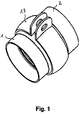
- Fig. 1 shows a conduit arrangement which comprises two mutually facing line ends 1 and 2.
- the line ends 1 and 2 are formed curved at least in sections.
- the line ends 1 and 2 are encompassed by a ball band clamp 13.
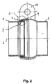
- Fig. 2 shows the line arrangement according to Fig. 1 in a sectional view.
- the line arrangement according to Fig. 2 comprises two mutually facing line ends 1, 2.
- the line ends 1, 2 are formed curved at least in sections.
- the first line end 1 surrounds the second line end 2 to form an overlap region 3.
- the overlap region 3 is in Fig. 2 highlighted by a circle.
- a receptacle 4 for a seal 5 is formed, which is positioned between the first line end 1 and the second line end 2.
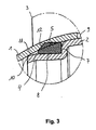
- Fig. 3 shows in an enlarged view the overlap region 3 according to Fig. 2 ,
- the receptacle 4 is designed as a stepped deposition.
- the receptacle 4 is formed in the second line end 2. More concretely, the step-shaped deposition is impressed on the jacket of the second line end 2.
- the receptacle 4 has an orthogonal to the line axis 6 oriented contact surface 7 and an aligned parallel to the line axis 6 Aufschiebe resolution 8.
- the second line end 2 has a stop region 9, on which the first line end 1 abuts against the second line end 2.
- the second line end has a closing edge 10, which bears against the inner wall 11 of the first line end 1.
- the plant of Closing edge 10 may be formed linear. As a result, the installation space in which the seal 5 is positioned, sealed.
- the seal 5 is designed as a sealing ring, which has a sealing edge 12.
- the sealing edge 12 is chamfered and is also on the inner wall 11 of the first line end 1 at.
- the gasket 5 has a soft material wound in a metal foil.
- the line ends 1, 2 are spherically curved, and at least partially concentric with each other.
- the first line end 1 surrounds the second line end second
- Fig. 4 shows in a sectional view of the line end 2, which is partially spherical in shape.
- the ball-shaped area is a closing edge 10, a stop area 9, a parallel to the line 6 oriented Aufschiebe resolution 8 and an orthogonal to the line axis 6 oriented contact surface 7 impressed.
- Fig. 5 shows a sectional view of a conduit assembly with a thickened second conduit end 2.
- the receptacle 4 is formed in a thickened portion 4a.
- the seal 5 is positioned in the receptacle 4.
- the receptacle 4 has a sliding surface 8 oriented parallel to the line axis 6.
- Fig. 6 shows a sectional view of a conduit arrangement with line ends 1, 2, on which connecting flanges 14 are arranged.
- the line ends 1, 2 are screwed together by screws 15.
- the line ends 1, 2 are formed as end pieces, which tubes 1a, 2a are assigned.
- the tubes 1a, 2a can be welded, screwed or pressed with the end pieces.
- the receptacle 4 is formed in a thickened region 4a, in the receptacle 4, the seal 5 is positioned.
- the receptacle 4 has a orthogonal to the line axis 6 oriented contact surface 7 and a parallel to the line axis 6 oriented Aufschiebe resolution 8.
- FIGS. 1 to 6 shown line arrangements or line ends found in exhaust systems of motor vehicles use.
- the piping arrangements described here show a maximum leakage of 0.1 l / min.
Landscapes
- Engineering & Computer Science (AREA)
- General Engineering & Computer Science (AREA)
- Mechanical Engineering (AREA)
- Chemical & Material Sciences (AREA)
- Combustion & Propulsion (AREA)
- Gasket Seals (AREA)
- Installation Of Indoor Wiring (AREA)
Abstract
Description
- Die Erfindung betrifft eine Leitungsanordnung, umfassend zwei einander zugewandte Leitungsenden, wobei das erste Leitungsende das zweite Leitungsende unter Ausbildung eines Überlappungsbereichs zumindest teilweise umgreift.
- Derartige Leitungsanordnungen sind aus dem Automobilbereich bekannt. Dort sind die Leitungen als Rohrenden ausgebildet, welche mittels einer Kugelbandschelle verbunden werden. Diese Leitungsanordnungen finden meistens im mittleren und hinteren Bereich der Abgasanlagen von Kraftfahrzeugen Verwendung.
- Die Leitungsenden werden ineinander geschoben und durch die Kugelbandschelle fixiert. Hierdurch entsteht eine sehr kompakte Verbindung. Durch die Auswölbung der Rohrenden ist ein Ausrichten oder Verdrehen der Rohrenden gegeneinander im noch unverspannten Zustand problemlos möglich, Nach dem Verspannen durch die Kugelverbandschelle ist eine sichere Fixierung der Leitungsenden sichergestellt.
- Kurz nach der Montage der bekannten Leitungsanordnungen weisen diese Leckageraten auf, die sich im Bereich kleiner 2 l/min bei 0,3 bar Innendruck bewegen. Nach längerer Zeit wird diese Leckagerate jedoch überschritten. Unter Umständen kann schon nach wenigen Stunden die genannte Leckagerate überschritten werden, wenn nämlich die Leitungsanordnung über 400°C erhitzt wird,
- Die bekannten Leitungsanordnungen können nicht zuverlässig die durch die Euronorm 4 und Euronorm 5 vorgeschriebene Leckagedichtheit erfüllen. Eine moderne Leitungsanordnung darf auch nach längerer Betriebsdauer eine Leckagerate von höchstens 0,2 I/min bei 0,3 bar Innendruck zeigen.
- Diese geforderte Dichtheit können die bekannten Leitungsanordnungen nicht dauerhaft gewährleisten.
- Der Erfindung liegt die Aufgabe zu Grunde, eine Leitungsanordnung zu realisieren, die selbst nach längerer Betriebsdauer eine hohe Dichtheit gewährleistet.
- Die vorliegende Erfindung löst die zuvor genannte Aufgabe durch die Merkmale des Patentanspruchs 1. Danach ist die eingangs genannte Leitungsanordnung dadurch gekennzeichnet, dass im Überlappungsbereich eine Aufnahme für eine Dichtung ausgebildet ist, die zwischen dem ersten Leitungsende und dem zweiten Leitungsende positioniert ist.
- Erfindungsgemäß ist erkannt worden, dass die Positionierung einer Dichtung zwischen den sich überlappenden Leitungsenden das Austreten von Gasen wirksam verhindert. Erfindungsgemäß ist insbesondere erkannt worden, dass eine Dichtung auf Grund ihrer Weichheit auftretende Spalte wirksam verschließen kann.
- Bei Kraftfahrzeugen treten auf Grund von Vibrationen, die durch den Motor oder die Fahrbahn angeregt werden, zwangsläufig kleine Spalte und Versatzräume auf. Bei den gattungsbildenden Leitungsanordnungen liegen die Mantelflächen der Leitungsenden lediglich aneinander und können nur durch plastische Verformung der anliegenden gewölbten Flächen abgedichtet werden. Die außen liegenden Mantelflächen sind ständig Witterungseinflüssen ausgesetzt.
- Erfindungsgemäß ist erkannt worden, dass die Positionierung einer Dichtung im Inneren der Leitungsanordnung, nämlich an den inneren Mantelflächen anliegend, die Dichtung zuverlässig vor Witterungseinflüssen schützt. Die im Inneren der Leitungsanordnung positionierte Dichtung wird durch den Mantel zumindest eines Leitungsendes abgeschirmt. Durch diese Ausgestaltung ist erfindungsgemäß realisiert, dass die Dichtung auch nach langer Betriebsdauer noch ihre Funktion erfüllen und die Leitungsanordnung zuverlässig abdichten kann.
- Folglich ist die eingangs genannte Aufgabe gelöst.
- Die Aufnahme könnte als stufenförmige Absetzung ausgebildet sein. Diese konkrete Ausgestaltung ist in fertigungstechnischer Hinsicht besonders vorteilhaft, da eine Stufenform problemlos einem Leitungsende aufgeprägt werden kann. Denkbar ist auch, die stufenförmige Absetzung durch ein Tiefziehverfahren einem Leitungsende aufzuprägen.
- Die Leitungsenden könnten dabei aus Metall gefertigt sein. Die Verwendung eines Metalls erlaubt eine besonders stabile und temperaturbeständige Ausgestaltung der Leitungsanordnung, so dass diese in Abgasanlagen von Kraftfahrzeugen Verwendung finden kann.
- Die Aufnahme könnte eine orthogonal zur Leitungsachse orientierte Anlagefläche und eine parallel zur Leitungsachse orientierte Aufschiebefläche aufweisen. Diese konkrete Ausgestaltung erlaubt ein problemloses Aufschieben der Dichtung auf das Leitungsende, dem die Aufnahme zugeordnet ist. Durch die senkrecht zur Leitungsachse orientierte Anlagefläche werden Fehler bei der Montage nahezu ausgeschlossen, da der Monteur einen Hinweis erhält, wo die Dichtung anliegen muss.
- Die Aufnahme könnte im zweiten Leitungsende ausgebildet sein. Hierdurch ist sichergestellt, dass das erste Leitungsende die Dichtung gegen äußere Einflüsse abdichten kann. Durch die Ausbildung der Aufnahme im zweiten Leitungsende wird durch den Mantel des ersten Leitungsendes und des zweiten Leitungsendes ein Einbauraum geschaffen, in dem die Dichtung gekammert ist.
- Vor diesem Hintergrund könnte die Aufnahme in einem verdickten Bereich ausgebildet sein. Durch diese konkrete Ausgestaltung ist ein sehr stabiles Leitungsende realisierbar.
- Das zweite Leitungsende könnte einen Anschlagbereich aufweisen, an dem das erste Leitungsende an dem zweiten Leitungsende anstößt. Diese konkrete Ausgestaltung begrenzt die axiale Verschiebbarkeit der Leitungsenden gegeneinander. Durch geeignete Dimensionierung des Anschlagsbereichs kann die Kompression der Dichtung durch die gegeneinander gepressten Leitungsenden eingestellt werden.
- Das zweite Leitungsende könnte eine Schließflanke aufweisen, die an der Innenwandung des ersten Leitungsendes anliegt. Diese konkrete Ausgestaltung bewirkt vorteilhaft eine Abdichtung des Einbauraums, in welchem die Dichtung positioniert ist. Hierdurch wird ein Spüleffekt durch Abgase an der Frontseite der Dichtung vermieden. Des Weiteren könnte die Schließflanke konisch verlaufend ausgebildet sein. Diese konkrete Ausgestaltung erlaubt ein problemloses Aufschieben der Dichtung auf das zweite Leitungsende. Ein Abscheuem der Dichtung oder ein Verklemmen der Dichtung beim Aufschieben auf das zweite Leitungsende werden wirksam vermieden.
- Die Dichtung könnte als Dichtring ausgebildet sein. Ein Dichtring lässt sich problemlos fertigen und kann das zweite Leitungsende umfänglich umgeben. Ein Dichtring lässt sich problemlos auf eine rohrförmige Leitung aufschieben.
- Der Dichtring könnte eine Dichtflanke aufweisen. Die Dichtflanke könnte derart abgeschrägt ausgebildet sein, dass die Innenwandung des ersten Leitungsendes am Dichtring anliegt. Diese konkrete Ausgestaltung erhöht die Lebensdauer des Dichtrings, da dieser nur schonend gestaucht wird, wenn die Leitungsenden gegeneinander gepresst werden. Die Dichtflanke erhöht des Weiteren die Anlagefläche des Dichtrings an der Innenwandung des ersten Leitungsendes.
- Die Dichtung könnte einen Weichstoff aufweisen, der mit einer Metallfolie aufgewickelt ist. Die Weichstoffe werden üblicherweise zusammen mit der Metallfolie gewickelt und in Form gepresst. Hierdurch erhält der Dichtring eine hohe Verformbarkeit, Dies erlaubt dem Dichtring, sich den Dimensionen des durch die Leitungsenden ausgebildeten Einbauraums anzupassen.
- Vor diesem Hintergrund ist denkbar, dass als Weichstoff Graphit, Glimmer oder asbestfreie Folien verwendet werden. Graphit ist besonders alterungsbeständig und behält eine dauerhafte Federeigenschaft. Aufgrund dieser Eigenschaft des Graphits können Mikrobewegungen der Leitungsenden infolge von Schwingungen kompensiert werden. Glimmer eignet sich für Dichtungen, die hohen Temperaturen standhalten müssen. Die Weichstoffe werden vorzugsweise zusammen mit einer Stahlfolie gewickelt, da Stahlfolie den Dichtring gegen Ausblasen sichert. Dies erlaubt, eine hohe Dichtheit der Leitungsanordnung auch bei hohen Innendrücken zu gewährleisten.
- Zumindest ein Leitungsende könnte zumindest abschnittsweise gewölbt ausgebildet sein. Diese Ausgestaltung erlaubt eine kostengünstige Ausformung eines Leitungsendes zur Aufnahme des anderen Leitungsendes, da Wölbungen durch Tiefziehprozesse ausgebildet werden können. Gewölbte Bereiche können des Weiteren auftretende Spannungen durch Versatz der Leitungsenden besonders gut aufnehmen, ohne die Dichtheit zu beeinträchtigen.
- Die Leitungsenden könnten kugelförmig gewölbt sein und zumindest bereichsweise konzentrisch aneinander liegen. Diese konkrete Ausgestaltung erlaubt ein problemloses Verkippen und Verwinkeln der Leitungsenden gegeneinander.
- Die Leitungsenden könnten von einer Kugelbandschelle umgriffen sein. Die Verwendung einer Kugelbandschelle erlaubt das feste Aneinanderpressen kugelförmig ausgebildeter Leitungsenden unter Verwendung nur einer Schraube. Hierdurch ist die Montage der Leitungsanordnung besonders problemlos zu realisieren.
- Die Leitungsenden könnten Flansche aufweisen, die mit den Leitungsenden einstückig ausgebildet sind. Hierdurch werden Lagerhaltungskosten minimiert und ein teilearmer Aufbau realisiert.
- Es gibt nun verschiedene Möglichkeiten, die Lehre der vorliegenden Erfindung in vorteilhafter Weise auszugestalten und weiterzubilden. Dazu ist einerseits auf die nachgeordneten Ansprüche, andererseits auf die nachfolgende Erläuterung eines bevorzugten Ausführungsbeispiels der erfindungsgemäßen Leitungsanordnung anhand der Zeichnung zu verweisen.
- In Verbindung mit der Erläuterung des bevorzugten Ausführungsbeispiels anhand der Zeichnung werden auch im Allgemeinen bevorzugte Ausgestaltungen und Weiterbildungen der Lehre erläutert.
- In der Zeichnung zeigen
- Fig. 1
- in einer perspektivischen Ansicht eine Leitungsanordnung, in der die Leitungsenden von einer Kugelbandschelle umgriffen sind,
- Fig. 2
- eine Schnittansicht der Leitungsanordnung gemäß
Fig. 1 , - Fig. 3
- eine Detailansicht der
Fig. 2 , - Fig. 4
- eine Schnittansicht des zweiten Leitungsendes,
- Fig. 5
- eine Schnittansicht einer Leitungsanordnung mit einem verdickten zweiten Leitungsende und
- Fig. 6
- eine Schnittansicht einer Leitungsanordnung mit Leitungsenden, an denen Verbindungsflansche angeordnet sind.
-
Fig. 1 zeigt eine Leitungsanordnung, welche zwei einander zugewandte Leitungsenden 1 und 2 umfasst. Die Leitungsenden 1 und 2 sind zumindest abschnittsweise gewölbt ausgebildet. Die Leitungsenden 1 und 2 sind von einer Kugelbandschelle 13 umgriffen. -
Fig. 2 zeigt die Leitungsanordnung gemäßFig. 1 in einer Schnittansicht. Die Leitungsanordnung gemäßFig. 2 umfasst zwei einander zugewandte Leitungsenden 1, 2. Die Leitungsenden 1, 2 sind zumindest abschnittsweise gewölbt ausgebildet. Das erste Leitungsende 1 umgreift das zweite Leitungsende 2 unter Ausbildung eines Überlappungsbereichs 3. Der Überlappungsbereich 3 ist inFig. 2 durch einen Kreis besonders hervorgehoben. Im Überlappungsbereich 3 ist eine Aufnahme 4 für eine Dichtung 5 ausgebildet, die zwischen dem ersten Leitungsende 1 und dem zweiten Leitungsende 2 positioniert ist. -
Fig. 3 zeigt in einer vergrößerten Ansicht den Überlappungsbereich 3 gemäßFig. 2 . Die Aufnahme 4 ist als stufenförmige Absetzung ausgebildet. Dabei ist die Aufnahme 4 im zweiten Leitungsende 2 ausgebildet. Ganz konkret ist die stufenförmige Absetzung dem Mantel des zweiten Leitungsendes 2 aufgeprägt. - Die Aufnahme 4 weist eine orthogonal zur Leitungsachse 6 orientierte Anlagefläche 7 und eine parallel zur Leitungsachse 6 orientierte Aufschiebefläche 8 auf.
- Das zweite Leitungsende 2 weist einen Anschlagbereich 9 auf, an dem das erste Leitungsende 1 an dem zweiten Leitungsende 2 anstößt.
- Das zweite Leitungsende weist eine Schließflanke 10 auf, die an der Innenwandung 11 des ersten Leitungsendes 1 anliegt. Die Anlage der Schließflanke 10 kann linienförmig ausgebildet sein. Hierdurch wird der Einbauraum, in dem die Dichtung 5 positioniert ist, abgedichtet.
- Die Dichtung 5 ist als Dichtring ausgebildet, der eine Dichtflanke 12 aufweist. Die Dichtflanke 12 ist abgeschrägt und liegt ebenfalls an der Innenwandung 11 des ersten Leitungsendes 1 an. Die Dichtung 5 weist einen Weichstoff auf, der in einer Metallfolie aufgewickelt ist.
- In den
Figuren 1 bis 3 ist gezeigt, dass die Leitungsenden 1, 2 kugelförmig gewölbt sind, und zumindest bereichsweise konzentrisch aneinander liegen. Dabei umgreift das erste Leitungsende 1 das zweite Leitungsende 2. -
Fig. 4 zeigt in einer Schnittansicht das Leitungsende 2, welches bereichsweise kugelförmig ausgebildet ist. Dem kugelförmig ausgebildeten Bereich ist eine Schließflanke 10, ein Anschlagbereich 9, eine parallel zur Leitungsache 6 orientierte Aufschiebefläche 8 und eine orthogonal zur Leitungsachse 6 orientierte Anlagefläche 7 aufgeprägt. -
Fig. 5 zeigt eine Schnittansicht einer Leitungsanordnung mit einem verdickten zweiten Leitungsende 2. Die Aufnahme 4 ist in einem verdickten Bereich 4a ausgebildet. In der Aufnahme 4 ist die Dichtung 5 positioniert. Die Aufnahme 4 weist eine parallel zur Leitungsachse 6 orientierte Aufschiebefläche 8 auf. -
Fig. 6 zeigt eine Schnittansicht einer Leitungsanordnung mit Leitungsenden 1, 2, an denen Verbindungsflansche 14 angeordnet sind. Die Leitungsenden 1, 2 sind durch Schrauben 15 miteinander verschraubt. Die Leitungsenden 1, 2 sind als Endstücke ausgebildet, denen Rohre 1a, 2a zugeordnet sind. Die Rohre 1a, 2a können mit den Endstücken verschweißt, verschraubt oder verpresst sein. - Die Aufnahme 4 ist in einem verdickten Bereich 4a ausgebildet, In der Aufnahme 4 ist die Dichtung 5 positioniert. Die Aufnahme 4 weist eine orthogonal zur Leitungsachse 6 orientierte Anlagefläche 7 und eine parallel zur Leitungsachse 6 orientierte Aufschiebefläche 8 auf.
- Die in den
Figuren 1 bis 6 gezeigten Leitungsanordnungen bzw. Leitungsenden finden in Abgasanlagen von Kraftfahrzeugen Verwendung. Die hier beschriebenen Leitungsanordnungen zeigen eine maximale Leckage von 0,1 I/min. - Hinsichtlich weiterer vorteilhafter Ausgestaltungen und Weiterbildungen der erfindungsgemäßen Lehre wird einerseits auf den allgemeinen Teil der Beschreibung und andererseits auf die beigefügten Patentansprüche verwiesen.
- Abschließend sei ganz besonders hervorgehoben, dass das zuvor rein willkürlich ausgewählte Ausführungsbeispiel lediglich zur Erörterung der erfindungsgemäßen Lehre dient, diese jedoch nicht auf dieses Ausführungsbeispiel einschränkt.
Claims (14)
- Leitungsanordnung, umfassend zwei einander zugewandte Leitungsenden (1, 2), wobei das erste Leitungsende (1) das zweite Leitungsende (2) unter Ausbildung eines Überlappungsbereichs (3) zumindest teilweise umgreift, dadurch gekennzeichnet, dass
im Überlappungsbereich (3) eine Aufnahme (4) für eine Dichtung (5) ausgebildet ist, die zwischen dem ersten Leitungsende (1) und dem zweiten Leitungsende (2) positioniert ist. - Leitungsanordnung nach Anspruch 1, dadurch gekennzeichnet, dass die Aufnahme (4) als stufenförmige Absetzung ausgebildet ist.
- Leitungsanordnung nach Anspruch 1 oder 2, dadurch gekennzeichnet, dass die Aufnahme (4) eine orthogonal zur Leitungsachse (6) orientierte Anlagefläche (7) und eine parallel zur Leitungsachse (6) orientierte Aufschiebefläche (8) aufweist.
- Leitungsanordnung nach einem der Ansprüche 1 bis 3, dadurch gekennzeichnet, dass die Aufnahme (4) im zweiten Leitungsende (2) ausgebildet ist.
- Leitungsanordnung nach einem der Ansprüche 1 bis 4, dadurch gekennzeichnet, dass die Aufnahme (4) in einem verdickten Bereich (4a) ausgebildet ist.
- Leitungsanordnung nach einem der Ansprüche 1 bis 5, dadurch gekennzeichnet, dass das zweite Leitungsende (2) einen Anschlagbereich (9) aufweist, an dem das erste Leitungsende (1) an dem zweiten Leitungsende (2) anstößt.
- Leitungsanordnung nach einem der Ansprüche 1 bis 6, dadurch gekennzeichnet, dass das zweite Leitungsende (2) eine Schließflanke (10) aufweist, die an der Innenwandung (11) des ersten Leitungsendes (1) anliegt.
- Leitungsanordnung nach einem der Ansprüche 1 bis 7, dadurch gekennzeichnet, dass die Dichtung (5) als Dichtring ausgebildet ist.
- Leitungsanordnung nach Anspruch 8, dadurch gekennzeichnet, dass der Dichtring (5) eine Dichtflanke (12) aufweist.
- Leitungsanordnung nach einem der Ansprüche 1 bis 9, dadurch gekennzeichnet, dass die Dichtung (5) einen Weichstoff aufweist, der mit einer Metallfolie aufgewickelt ist.
- Leitungsanordnung nach einem der Ansprüche 1 bis 10, dadurch gekennzeichnet, dass zumindest ein Leitungsende (1, 2) zumindest abschnittsweise gewölbt ausgebildet ist.
- Leitungsanordnung nach einem der Ansprüche 1 bis 11, dadurch gekennzeichnet, dass die Leitungsenden (1, 2) kugelförmig gewölbt sind und zumindest bereichsweise konzentrisch aneinander liegen.
- Leitungsanordnung nach einem der Ansprüche 1 bis 12, dadurch gekennzeichnet, dass die Leitungsenden (1, 2) von einer Kugelbandschelle (13) umgriffen sind.
- Leitungsanordnung nach einem der Ansprüche 1 bis 12, dadurch gekennzeichnet, dass die Leitungsenden (1, 2) Flansche (14) aufweisen.
Applications Claiming Priority (1)
| Application Number | Priority Date | Filing Date | Title |
|---|---|---|---|
| DE200610060215 DE102006060215B4 (de) | 2006-12-18 | 2006-12-18 | Leitungsanordnung mit einer Dichtung im Überlappungsbereich |
Publications (2)
| Publication Number | Publication Date |
|---|---|
| EP1950482A1 true EP1950482A1 (de) | 2008-07-30 |
| EP1950482B1 EP1950482B1 (de) | 2013-11-06 |
Family
ID=39431440
Family Applications (1)
| Application Number | Title | Priority Date | Filing Date |
|---|---|---|---|
| EP20070018151 Not-in-force EP1950482B1 (de) | 2006-12-18 | 2007-09-14 | Leitungsanordnung mit einer Dichtung im Überlappungsbereich |
Country Status (2)
| Country | Link |
|---|---|
| EP (1) | EP1950482B1 (de) |
| DE (1) | DE102006060215B4 (de) |
Cited By (1)
| Publication number | Priority date | Publication date | Assignee | Title |
|---|---|---|---|---|
| GB2576153A (en) * | 2018-08-06 | 2020-02-12 | Jaguar Land Rover Ltd | Coupling apparatus |
Families Citing this family (3)
| Publication number | Priority date | Publication date | Assignee | Title |
|---|---|---|---|---|
| DE102008058461A1 (de) | 2008-11-21 | 2010-05-27 | Volkswagen Ag | Kugelzonenverbindungsvorrichtung |
| DE102011010060A1 (de) | 2011-02-02 | 2011-11-17 | Daimler Ag | Verbindungsanordnung eines ersten Rohrteils mit einem zweiten Rohrteil |
| NL2033881B1 (en) * | 2022-12-30 | 2024-07-12 | Walraven Holding Bv J Van | Pipe clip with width curvature at flanges |
Citations (7)
| Publication number | Priority date | Publication date | Assignee | Title |
|---|---|---|---|---|
| DE434908C (de) | 1925-02-01 | 1926-10-05 | Abt Hoerder Ver | Verfahren zum Verlegen von Rohrstraengen |
| DE821890C (de) | 1949-04-26 | 1951-11-22 | Karl Peter May | Rohrgelenk |
| US2758851A (en) | 1951-04-11 | 1956-08-14 | Solar Aircraft Co | Packed ball and socket pipe joint |
| FR1236037A (fr) | 1959-06-02 | 1960-07-15 | Loing Verreries | Raccord sphérique |
| EP0242868A1 (de) | 1986-04-22 | 1987-10-28 | Nippon Reinz Co.,Ltd. | Verbindungsteile, die aus Flanschen bestehen |
| EP0672857A1 (de) | 1994-03-16 | 1995-09-20 | Thyssen Polymer Gmbh | Gelenkrohr |
| DE102004056429A1 (de) | 2004-11-23 | 2006-06-01 | Daimlerchrysler Ag | Vorrichtung zur Axialverbindung von zwei Rohrelementen |
Family Cites Families (6)
| Publication number | Priority date | Publication date | Assignee | Title |
|---|---|---|---|---|
| DE843936C (de) * | 1950-08-11 | 1952-07-14 | Gewerkschaft Reuss | Schnellkupplung fuer Rohre mit Bunden, insbesondere Blasversatzrohre |
| DE1667568U (de) * | 1952-02-14 | 1953-11-26 | Siepmann Werke Ag | Kupplung fuer rohre, insbesondere blasversatzrohre. |
| DE1937399C3 (de) * | 1969-07-23 | 1981-02-12 | Gamah Corp., (N.D.Ges.D.Staates Californien), Denver, Col. (V.St.A.) | Vorrichtung zum abgedichteten Aneinanderkuppeln von fließfähige Medien führenden Elementen, beispielsweise Leitungsrohren |
| DE2911448C2 (de) * | 1979-03-23 | 1984-05-24 | Rheinmetall GmbH, 4000 Düsseldorf | Rohrverbindung |
| DE3509774A1 (de) * | 1985-03-19 | 1986-10-02 | Witzenmann GmbH, Metallschlauch-Fabrik Pforzheim, 7530 Pforzheim | Rohrverbindung |
| DE10336351B3 (de) * | 2003-08-08 | 2004-11-11 | Rasmussen Gmbh | Rohrschelle |
-
2006
- 2006-12-18 DE DE200610060215 patent/DE102006060215B4/de not_active Expired - Fee Related
-
2007
- 2007-09-14 EP EP20070018151 patent/EP1950482B1/de not_active Not-in-force
Patent Citations (7)
| Publication number | Priority date | Publication date | Assignee | Title |
|---|---|---|---|---|
| DE434908C (de) | 1925-02-01 | 1926-10-05 | Abt Hoerder Ver | Verfahren zum Verlegen von Rohrstraengen |
| DE821890C (de) | 1949-04-26 | 1951-11-22 | Karl Peter May | Rohrgelenk |
| US2758851A (en) | 1951-04-11 | 1956-08-14 | Solar Aircraft Co | Packed ball and socket pipe joint |
| FR1236037A (fr) | 1959-06-02 | 1960-07-15 | Loing Verreries | Raccord sphérique |
| EP0242868A1 (de) | 1986-04-22 | 1987-10-28 | Nippon Reinz Co.,Ltd. | Verbindungsteile, die aus Flanschen bestehen |
| EP0672857A1 (de) | 1994-03-16 | 1995-09-20 | Thyssen Polymer Gmbh | Gelenkrohr |
| DE102004056429A1 (de) | 2004-11-23 | 2006-06-01 | Daimlerchrysler Ag | Vorrichtung zur Axialverbindung von zwei Rohrelementen |
Cited By (2)
| Publication number | Priority date | Publication date | Assignee | Title |
|---|---|---|---|---|
| GB2576153A (en) * | 2018-08-06 | 2020-02-12 | Jaguar Land Rover Ltd | Coupling apparatus |
| GB2576153B (en) * | 2018-08-06 | 2021-06-23 | Jaguar Land Rover Ltd | Rotatable coupling with clamping means and sealing means for an exhaust system |
Also Published As
| Publication number | Publication date |
|---|---|
| EP1950482B1 (de) | 2013-11-06 |
| DE102006060215B4 (de) | 2010-03-18 |
| DE102006060215A1 (de) | 2008-06-26 |
Similar Documents
| Publication | Publication Date | Title |
|---|---|---|
| DE102016120436A1 (de) | Dichtringanordnung | |
| EP1688655A1 (de) | Flanschverbindung für Leitungen | |
| DE19937444C1 (de) | Vorrichtung zur Verteilung von Kraftstoff für Kraftstoffeinspritzanlagen von Verbrennungsmotoren | |
| EP1950482B1 (de) | Leitungsanordnung mit einer Dichtung im Überlappungsbereich | |
| EP0854313A1 (de) | Doppelkegel-Kupplungs-Nippel einer Stahlrohrleitung | |
| EP1398554B1 (de) | Schlauchleitung und Verfahren zu deren Herstellung | |
| DE102014011606B4 (de) | Abgassystem für eine Brennkraftmaschine | |
| DE102010009618B4 (de) | Anschlussvorrichtung für ein modulares Installationssystem | |
| DE102016100598A1 (de) | Anordnung zum fluiddichten Anschließen einer Rohrleitung sowie Ausgleichselement für die Anordnung | |
| DE202019104006U1 (de) | Modularer Verteiler für Rohrinstallationen | |
| DE102006043864A1 (de) | Vorrichtung zur gasdichten Montage eines Krümmerrohrs | |
| DE202005019046U1 (de) | Vorrichtung zur gasdichten Montage eines Krümmerrohrs | |
| AT524438A4 (de) | Wanddurchführungseinrichtung | |
| EP1479885B1 (de) | Abgasanlage | |
| DE10216721B4 (de) | Verbindungssystem für die form-und/oder kraftschlüssige Verbindung zweier Bauteile | |
| EP0950841B1 (de) | Lösbare Rohrverbindung | |
| DE202012003173U1 (de) | Formteil mit mindestens einer Steckmuffe aus Kunststoff sowie mit einer ringförmigen Lippendichtung und Rohrverbindungsanordnung mit einem solchen Formteil | |
| DE102009031239A1 (de) | Rohrverbinder zur fluiddichten Verbindung von Rohren | |
| DE102013111653A1 (de) | Rohrbride für Verbrennungsluftrohre sowie Abgasrohrsystem | |
| EP1873368B1 (de) | Flexibles Metallrohr mit Dichtring | |
| DE102008058958A1 (de) | Rohrverbindungsanordnung für ein Antriebsaggregat eines Fahrzeugs und Brennstoffzellensystem | |
| DE19743926C1 (de) | Verbindungsstück für Rohrleitungen | |
| DE102023124525A1 (de) | Zweiteilige Schelle für ein Rohrsystem | |
| EP3165804B1 (de) | Verbindung zweier rohrbruchdichtschellen sowie dichtungsanordnung | |
| DE102010040289A1 (de) | Rohrsteckverbindung, insbesondere für das Abgassystem einer Brennkraftmaschine |
Legal Events
| Date | Code | Title | Description |
|---|---|---|---|
| PUAI | Public reference made under article 153(3) epc to a published international application that has entered the european phase |
Free format text: ORIGINAL CODE: 0009012 |
|
| AK | Designated contracting states |
Kind code of ref document: A1 Designated state(s): AT BE BG CH CY CZ DE DK EE ES FI FR GB GR HU IE IS IT LI LT LU LV MC MT NL PL PT RO SE SI SK TR |
|
| AX | Request for extension of the european patent |
Extension state: AL BA HR MK RS |
|
| 17P | Request for examination filed |
Effective date: 20080916 |
|
| AKX | Designation fees paid |
Designated state(s): AT BE BG CH CY CZ DE DK EE ES FI FR GB GR HU IE IS IT LI LT LU LV MC MT NL PL PT RO SE SI SK TR |
|
| 17Q | First examination report despatched |
Effective date: 20100409 |
|
| RAP1 | Party data changed (applicant data changed or rights of an application transferred) |
Owner name: ELRINGKLINGER AG |
|
| GRAJ | Information related to disapproval of communication of intention to grant by the applicant or resumption of examination proceedings by the epo deleted |
Free format text: ORIGINAL CODE: EPIDOSDIGR1 |
|
| GRAP | Despatch of communication of intention to grant a patent |
Free format text: ORIGINAL CODE: EPIDOSNIGR1 |
|
| GRAP | Despatch of communication of intention to grant a patent |
Free format text: ORIGINAL CODE: EPIDOSNIGR1 |
|
| GRAP | Despatch of communication of intention to grant a patent |
Free format text: ORIGINAL CODE: EPIDOSNIGR1 |
|
| INTG | Intention to grant announced |
Effective date: 20130523 |
|
| GRAS | Grant fee paid |
Free format text: ORIGINAL CODE: EPIDOSNIGR3 |
|
| GRAA | (expected) grant |
Free format text: ORIGINAL CODE: 0009210 |
|
| AK | Designated contracting states |
Kind code of ref document: B1 Designated state(s): AT BE BG CH CY CZ DE DK EE ES FI FR GB GR HU IE IS IT LI LT LU LV MC MT NL PL PT RO SE SI SK TR |
|
| REG | Reference to a national code |
Ref country code: GB Ref legal event code: FG4D Free format text: NOT ENGLISH |
|
| REG | Reference to a national code |
Ref country code: CH Ref legal event code: EP |
|
| REG | Reference to a national code |
Ref country code: AT Ref legal event code: REF Ref document number: 639739 Country of ref document: AT Kind code of ref document: T Effective date: 20131215 |
|
| REG | Reference to a national code |
Ref country code: IE Ref legal event code: FG4D Free format text: LANGUAGE OF EP DOCUMENT: GERMAN |
|
| REG | Reference to a national code |
Ref country code: DE Ref legal event code: R096 Ref document number: 502007012455 Country of ref document: DE Effective date: 20140102 |
|
| REG | Reference to a national code |
Ref country code: NL Ref legal event code: VDEP Effective date: 20131106 |
|
| REG | Reference to a national code |
Ref country code: LT Ref legal event code: MG4D |
|
| PG25 | Lapsed in a contracting state [announced via postgrant information from national office to epo] |
Ref country code: IS Free format text: LAPSE BECAUSE OF FAILURE TO SUBMIT A TRANSLATION OF THE DESCRIPTION OR TO PAY THE FEE WITHIN THE PRESCRIBED TIME-LIMIT Effective date: 20140306 Ref country code: NL Free format text: LAPSE BECAUSE OF FAILURE TO SUBMIT A TRANSLATION OF THE DESCRIPTION OR TO PAY THE FEE WITHIN THE PRESCRIBED TIME-LIMIT Effective date: 20131106 Ref country code: SE Free format text: LAPSE BECAUSE OF FAILURE TO SUBMIT A TRANSLATION OF THE DESCRIPTION OR TO PAY THE FEE WITHIN THE PRESCRIBED TIME-LIMIT Effective date: 20131106 Ref country code: LT Free format text: LAPSE BECAUSE OF FAILURE TO SUBMIT A TRANSLATION OF THE DESCRIPTION OR TO PAY THE FEE WITHIN THE PRESCRIBED TIME-LIMIT Effective date: 20131106 Ref country code: FI Free format text: LAPSE BECAUSE OF FAILURE TO SUBMIT A TRANSLATION OF THE DESCRIPTION OR TO PAY THE FEE WITHIN THE PRESCRIBED TIME-LIMIT Effective date: 20131106 |
|
| PG25 | Lapsed in a contracting state [announced via postgrant information from national office to epo] |
Ref country code: LV Free format text: LAPSE BECAUSE OF FAILURE TO SUBMIT A TRANSLATION OF THE DESCRIPTION OR TO PAY THE FEE WITHIN THE PRESCRIBED TIME-LIMIT Effective date: 20131106 Ref country code: ES Free format text: LAPSE BECAUSE OF FAILURE TO SUBMIT A TRANSLATION OF THE DESCRIPTION OR TO PAY THE FEE WITHIN THE PRESCRIBED TIME-LIMIT Effective date: 20131106 |
|
| PG25 | Lapsed in a contracting state [announced via postgrant information from national office to epo] |
Ref country code: PT Free format text: LAPSE BECAUSE OF FAILURE TO SUBMIT A TRANSLATION OF THE DESCRIPTION OR TO PAY THE FEE WITHIN THE PRESCRIBED TIME-LIMIT Effective date: 20140306 |
|
| PG25 | Lapsed in a contracting state [announced via postgrant information from national office to epo] |
Ref country code: EE Free format text: LAPSE BECAUSE OF FAILURE TO SUBMIT A TRANSLATION OF THE DESCRIPTION OR TO PAY THE FEE WITHIN THE PRESCRIBED TIME-LIMIT Effective date: 20131106 |
|
| REG | Reference to a national code |
Ref country code: DE Ref legal event code: R097 Ref document number: 502007012455 Country of ref document: DE |
|
| PG25 | Lapsed in a contracting state [announced via postgrant information from national office to epo] |
Ref country code: CZ Free format text: LAPSE BECAUSE OF FAILURE TO SUBMIT A TRANSLATION OF THE DESCRIPTION OR TO PAY THE FEE WITHIN THE PRESCRIBED TIME-LIMIT Effective date: 20131106 Ref country code: RO Free format text: LAPSE BECAUSE OF FAILURE TO SUBMIT A TRANSLATION OF THE DESCRIPTION OR TO PAY THE FEE WITHIN THE PRESCRIBED TIME-LIMIT Effective date: 20131106 Ref country code: IT Free format text: LAPSE BECAUSE OF FAILURE TO SUBMIT A TRANSLATION OF THE DESCRIPTION OR TO PAY THE FEE WITHIN THE PRESCRIBED TIME-LIMIT Effective date: 20131106 Ref country code: PL Free format text: LAPSE BECAUSE OF FAILURE TO SUBMIT A TRANSLATION OF THE DESCRIPTION OR TO PAY THE FEE WITHIN THE PRESCRIBED TIME-LIMIT Effective date: 20131106 Ref country code: SK Free format text: LAPSE BECAUSE OF FAILURE TO SUBMIT A TRANSLATION OF THE DESCRIPTION OR TO PAY THE FEE WITHIN THE PRESCRIBED TIME-LIMIT Effective date: 20131106 |
|
| PLBE | No opposition filed within time limit |
Free format text: ORIGINAL CODE: 0009261 |
|
| STAA | Information on the status of an ep patent application or granted ep patent |
Free format text: STATUS: NO OPPOSITION FILED WITHIN TIME LIMIT |
|
| PG25 | Lapsed in a contracting state [announced via postgrant information from national office to epo] |
Ref country code: DK Free format text: LAPSE BECAUSE OF FAILURE TO SUBMIT A TRANSLATION OF THE DESCRIPTION OR TO PAY THE FEE WITHIN THE PRESCRIBED TIME-LIMIT Effective date: 20131106 |
|
| 26N | No opposition filed |
Effective date: 20140807 |
|
| REG | Reference to a national code |
Ref country code: DE Ref legal event code: R097 Ref document number: 502007012455 Country of ref document: DE Effective date: 20140807 |
|
| PG25 | Lapsed in a contracting state [announced via postgrant information from national office to epo] |
Ref country code: SI Free format text: LAPSE BECAUSE OF FAILURE TO SUBMIT A TRANSLATION OF THE DESCRIPTION OR TO PAY THE FEE WITHIN THE PRESCRIBED TIME-LIMIT Effective date: 20131106 |
|
| PG25 | Lapsed in a contracting state [announced via postgrant information from national office to epo] |
Ref country code: LU Free format text: LAPSE BECAUSE OF FAILURE TO SUBMIT A TRANSLATION OF THE DESCRIPTION OR TO PAY THE FEE WITHIN THE PRESCRIBED TIME-LIMIT Effective date: 20140914 Ref country code: MC Free format text: LAPSE BECAUSE OF FAILURE TO SUBMIT A TRANSLATION OF THE DESCRIPTION OR TO PAY THE FEE WITHIN THE PRESCRIBED TIME-LIMIT Effective date: 20131106 |
|
| REG | Reference to a national code |
Ref country code: CH Ref legal event code: PL |
|
| GBPC | Gb: european patent ceased through non-payment of renewal fee |
Effective date: 20140914 |
|
| REG | Reference to a national code |
Ref country code: IE Ref legal event code: MM4A |
|
| PG25 | Lapsed in a contracting state [announced via postgrant information from national office to epo] |
Ref country code: BE Free format text: LAPSE BECAUSE OF NON-PAYMENT OF DUE FEES Effective date: 20140930 |
|
| REG | Reference to a national code |
Ref country code: DE Ref legal event code: R082 Ref document number: 502007012455 Country of ref document: DE Representative=s name: HOEGER, STELLRECHT & PARTNER PATENTANWAELTE MB, DE |
|
| PG25 | Lapsed in a contracting state [announced via postgrant information from national office to epo] |
Ref country code: CH Free format text: LAPSE BECAUSE OF NON-PAYMENT OF DUE FEES Effective date: 20140930 Ref country code: LI Free format text: LAPSE BECAUSE OF NON-PAYMENT OF DUE FEES Effective date: 20140930 Ref country code: GB Free format text: LAPSE BECAUSE OF NON-PAYMENT OF DUE FEES Effective date: 20140914 |
|
| PG25 | Lapsed in a contracting state [announced via postgrant information from national office to epo] |
Ref country code: IE Free format text: LAPSE BECAUSE OF NON-PAYMENT OF DUE FEES Effective date: 20140914 |
|
| REG | Reference to a national code |
Ref country code: AT Ref legal event code: MM01 Ref document number: 639739 Country of ref document: AT Kind code of ref document: T Effective date: 20140914 |
|
| PG25 | Lapsed in a contracting state [announced via postgrant information from national office to epo] |
Ref country code: AT Free format text: LAPSE BECAUSE OF NON-PAYMENT OF DUE FEES Effective date: 20140914 |
|
| PG25 | Lapsed in a contracting state [announced via postgrant information from national office to epo] |
Ref country code: BG Free format text: LAPSE BECAUSE OF FAILURE TO SUBMIT A TRANSLATION OF THE DESCRIPTION OR TO PAY THE FEE WITHIN THE PRESCRIBED TIME-LIMIT Effective date: 20131106 |
|
| PG25 | Lapsed in a contracting state [announced via postgrant information from national office to epo] |
Ref country code: CY Free format text: LAPSE BECAUSE OF FAILURE TO SUBMIT A TRANSLATION OF THE DESCRIPTION OR TO PAY THE FEE WITHIN THE PRESCRIBED TIME-LIMIT Effective date: 20131106 Ref country code: MT Free format text: LAPSE BECAUSE OF FAILURE TO SUBMIT A TRANSLATION OF THE DESCRIPTION OR TO PAY THE FEE WITHIN THE PRESCRIBED TIME-LIMIT Effective date: 20131106 Ref country code: GR Free format text: LAPSE BECAUSE OF FAILURE TO SUBMIT A TRANSLATION OF THE DESCRIPTION OR TO PAY THE FEE WITHIN THE PRESCRIBED TIME-LIMIT Effective date: 20140207 |
|
| PG25 | Lapsed in a contracting state [announced via postgrant information from national office to epo] |
Ref country code: HU Free format text: LAPSE BECAUSE OF FAILURE TO SUBMIT A TRANSLATION OF THE DESCRIPTION OR TO PAY THE FEE WITHIN THE PRESCRIBED TIME-LIMIT; INVALID AB INITIO Effective date: 20070914 Ref country code: TR Free format text: LAPSE BECAUSE OF FAILURE TO SUBMIT A TRANSLATION OF THE DESCRIPTION OR TO PAY THE FEE WITHIN THE PRESCRIBED TIME-LIMIT Effective date: 20131106 |
|
| REG | Reference to a national code |
Ref country code: FR Ref legal event code: PLFP Year of fee payment: 10 |
|
| PGFP | Annual fee paid to national office [announced via postgrant information from national office to epo] |
Ref country code: DE Payment date: 20160922 Year of fee payment: 10 |
|
| PGFP | Annual fee paid to national office [announced via postgrant information from national office to epo] |
Ref country code: FR Payment date: 20160922 Year of fee payment: 10 |
|
| REG | Reference to a national code |
Ref country code: DE Ref legal event code: R119 Ref document number: 502007012455 Country of ref document: DE |
|
| REG | Reference to a national code |
Ref country code: FR Ref legal event code: ST Effective date: 20180531 |
|
| PG25 | Lapsed in a contracting state [announced via postgrant information from national office to epo] |
Ref country code: DE Free format text: LAPSE BECAUSE OF NON-PAYMENT OF DUE FEES Effective date: 20180404 |
|
| PG25 | Lapsed in a contracting state [announced via postgrant information from national office to epo] |
Ref country code: FR Free format text: LAPSE BECAUSE OF NON-PAYMENT OF DUE FEES Effective date: 20171002 |