EP1949072B1 - Sensorelement für gassensoren und verfahren zum betrieb desselben - Google Patents
Sensorelement für gassensoren und verfahren zum betrieb desselben Download PDFInfo
- Publication number
- EP1949072B1 EP1949072B1 EP06807427.7A EP06807427A EP1949072B1 EP 1949072 B1 EP1949072 B1 EP 1949072B1 EP 06807427 A EP06807427 A EP 06807427A EP 1949072 B1 EP1949072 B1 EP 1949072B1
- Authority
- EP
- European Patent Office
- Prior art keywords
- sensor element
- measuring
- sensor
- measuring electrodes
- electrodes
- Prior art date
- Legal status (The legal status is an assumption and is not a legal conclusion. Google has not performed a legal analysis and makes no representation as to the accuracy of the status listed.)
- Not-in-force
Links
Images



Classifications
-
- G—PHYSICS
- G01—MEASURING; TESTING
- G01N—INVESTIGATING OR ANALYSING MATERIALS BY DETERMINING THEIR CHEMICAL OR PHYSICAL PROPERTIES
- G01N15/00—Investigating characteristics of particles; Investigating permeability, pore-volume or surface-area of porous materials
- G01N15/06—Investigating concentration of particle suspensions
- G01N15/0656—Investigating concentration of particle suspensions using electric, e.g. electrostatic methods or magnetic methods
-
- F—MECHANICAL ENGINEERING; LIGHTING; HEATING; WEAPONS; BLASTING
- F01—MACHINES OR ENGINES IN GENERAL; ENGINE PLANTS IN GENERAL; STEAM ENGINES
- F01N—GAS-FLOW SILENCERS OR EXHAUST APPARATUS FOR MACHINES OR ENGINES IN GENERAL; GAS-FLOW SILENCERS OR EXHAUST APPARATUS FOR INTERNAL-COMBUSTION ENGINES
- F01N11/00—Monitoring or diagnostic devices for exhaust-gas treatment apparatus
-
- F—MECHANICAL ENGINEERING; LIGHTING; HEATING; WEAPONS; BLASTING
- F01—MACHINES OR ENGINES IN GENERAL; ENGINE PLANTS IN GENERAL; STEAM ENGINES
- F01N—GAS-FLOW SILENCERS OR EXHAUST APPARATUS FOR MACHINES OR ENGINES IN GENERAL; GAS-FLOW SILENCERS OR EXHAUST APPARATUS FOR INTERNAL-COMBUSTION ENGINES
- F01N11/00—Monitoring or diagnostic devices for exhaust-gas treatment apparatus
- F01N11/002—Monitoring or diagnostic devices for exhaust-gas treatment apparatus the diagnostic devices measuring or estimating temperature or pressure in, or downstream of the exhaust apparatus
-
- F—MECHANICAL ENGINEERING; LIGHTING; HEATING; WEAPONS; BLASTING
- F01—MACHINES OR ENGINES IN GENERAL; ENGINE PLANTS IN GENERAL; STEAM ENGINES
- F01N—GAS-FLOW SILENCERS OR EXHAUST APPARATUS FOR MACHINES OR ENGINES IN GENERAL; GAS-FLOW SILENCERS OR EXHAUST APPARATUS FOR INTERNAL-COMBUSTION ENGINES
- F01N2560/00—Exhaust systems with means for detecting or measuring exhaust gas components or characteristics
- F01N2560/05—Exhaust systems with means for detecting or measuring exhaust gas components or characteristics the means being a particulate sensor
-
- F—MECHANICAL ENGINEERING; LIGHTING; HEATING; WEAPONS; BLASTING
- F01—MACHINES OR ENGINES IN GENERAL; ENGINE PLANTS IN GENERAL; STEAM ENGINES
- F01N—GAS-FLOW SILENCERS OR EXHAUST APPARATUS FOR MACHINES OR ENGINES IN GENERAL; GAS-FLOW SILENCERS OR EXHAUST APPARATUS FOR INTERNAL-COMBUSTION ENGINES
- F01N2560/00—Exhaust systems with means for detecting or measuring exhaust gas components or characteristics
- F01N2560/06—Exhaust systems with means for detecting or measuring exhaust gas components or characteristics the means being a temperature sensor
-
- Y—GENERAL TAGGING OF NEW TECHNOLOGICAL DEVELOPMENTS; GENERAL TAGGING OF CROSS-SECTIONAL TECHNOLOGIES SPANNING OVER SEVERAL SECTIONS OF THE IPC; TECHNICAL SUBJECTS COVERED BY FORMER USPC CROSS-REFERENCE ART COLLECTIONS [XRACs] AND DIGESTS
- Y02—TECHNOLOGIES OR APPLICATIONS FOR MITIGATION OR ADAPTATION AGAINST CLIMATE CHANGE
- Y02T—CLIMATE CHANGE MITIGATION TECHNOLOGIES RELATED TO TRANSPORTATION
- Y02T10/00—Road transport of goods or passengers
- Y02T10/10—Internal combustion engine [ICE] based vehicles
- Y02T10/40—Engine management systems
Definitions
- the invention is based on a sensor element for the determination of particles in gas mixtures, a gas sensor containing this, as well as their use according to the type defined in the preamble of the independent claims.
- sensors are needed with which an accurate determination of the particle concentration present in a combustion exhaust gas can be made possible even in long-term operation.
- a load prediction for example, provided in an exhaust system diesel particulate filter in order to achieve high system security and thereby be able to use cheaper filter materials can.
- a sensor for detecting particles in a fluid flow which is designed on the basis of a ceramic multilayer substrate. It comprises two spaced-apart measuring electrodes, which are exposed to the combustion exhaust gas to be examined. If soot is deposited between the two measuring electrodes, a current flow between the measuring electrodes occurs when a voltage is applied to the measuring electrodes.
- a layered heating element makes it possible to free the electrodes or their surroundings by thermal means from deposited soot particles.
- the sensor further comprises a temperature measuring element with which the temperature of the sensor can be detected. The heating element is located within the laminate of the sensor between the temperature measuring element and the measuring electrodes.
- a disadvantage of this construction of the sensor is that conventional temperature measuring elements of ceramic sensors have resistance printed conductors with an increased electrical resistance, which can only be produced by complicated production methods such as, for example, photofinrowing methods.
- a sensor element for gas sensors in particular for the determination of particles in gas mixtures, is already known.
- the sensor element further comprises an electrochemical measuring element exposed to the gas mixture to be determined with two measuring electrodes and a temperature measuring element which can be arranged at any point in the soot filter body 13 of the particle filter.
- the bifunctional can also determine the temperature.
- a first electrode can also serve as a temperature measuring element.
- the temperature measuring element in this case comprises a resistance track, which has an electrical resistance of about 100 ohms at 0 ° C.
- a humidity sensor with the ability to measure the temperature is also out of the JP 57-110948 A known. From the US 2003/0196499 A1 a particle sensor is already known, which has a heating element and a temperature measuring element in addition to the measuring electrodes.
- Object of the present invention is to provide a sensor element for sensors and a method for determining the concentration of particles in gas mixtures, which allows accurate temperature control and yet can be produced inexpensively.
- the sensor element, the gas sensor or the method having the characterizing features of the independent claims have the advantage that the problem underlying the invention is achieved in an advantageous manner. This is based in particular on the fact that it is possible to fall back on a sensor element with a simple structure, wherein one in the Sensor element integrated temperature measuring element can be realized in a particularly cost-effective manner.
- the temperature measuring element Since the temperature measuring element has a resistance conductor track with relatively low electrical resistance, it can be realized in a simple manner according to the invention by means of the so-called thick-film technique on a ceramic substrate of the sensor element, while conventional temperature measuring elements realized in ceramic gas sensors have a higher electrical resistance and whose underlying resistance conductor track is costly Thin-film technology is produced.
- the temperature measuring element comprises a resistance conductor track which has conductor track areas bridged by burn gaps. This allows a particularly simple adjustment of the temperature measuring element after its production, since an interruption of the electrically conductive firing paths by supplying energy leads to a virtual extension of the resistance track and thus to an increase of the total resistance.
- either one of the two measuring electrodes (16) is at least partially additionally designed as a resistance track of the heating element (40) and the other of the two measuring electrodes (14) is at least partially additionally designed as resistance track of the temperature measuring element (30), or the other of the two measuring electrodes (14) is at least partially additionally designed as a resistance track of the temperature measuring element (30) and of the heating element (40).
- an evaluation device which determines a change in the voltage applied between the measuring electrodes of the measuring element current flow or electrical resistance, taking into account the measurement temperature and outputs the result as a measure of a particle concentration or a particle mass flow.
- the sensor element or the method for operating the same is advantageously suitable for monitoring the mode of operation of a diesel engine or for checking the functionality or the loading state of a particulate filter.
- FIG. 1 a basic structure of an embodiment of a sensor element is shown.
- the sensor element 10 is a ceramic sensor element which serves to determine particles, such as soot particles, in a gas mixture surrounding the sensor element.
- the sensor element 10 includes, for example, a plurality of oxygen ion conductive solid electrolyte layers 11a, 11b and 11c.
- the solid electrolyte layers 11a and 11c are embodied as ceramic foils and form a planar ceramic body. They preferably consist of an oxygen-ion-conducting solid electrolyte material, such as Y 2 O 3 stabilized or partially stabilized ZrO 2 .
- the solid electrolyte layer 11b is produced by screen printing of a pasty ceramic material, for example, on the solid electrolyte layer 11a.
- the ceramic component of the pasty material used here is preferably the same solid electrolyte material from which the solid electrolyte layers 11a, 11c also consist.
- the sensor element 10 for example, a plurality of electrically insulating ceramic layers 12a, 12b, 12c, 12d, 12e and 12f.
- the layers 12a-12f are also produced by screen printing of a pasty ceramic material, for example on the solid electrolyte layers 11a, 11c.
- Barium-containing aluminum oxide is used as the ceramic component of the pasty material, since this is also used in Thermal cycling over a long period of time has a largely constant high electrical resistance.
- the use of ceria or the addition of other alkaline earth oxides is possible.
- the integrated shape of the planar ceramic body of the sensor element 10 is made by laminating the ceramic sheets printed with the solid electrolyte layer 11b and functional layers as well as the layers 12a-12f and then sintering the laminated structure in a manner known per se.
- the sensor element 10 further has a ceramic heating element 40, which is designed in the form of an electrical resistance track and the heating of the sensor element 10 is used in particular to the temperature of the gas mixture to be determined or the burning of deposited on the large surfaces of the sensor element 10 soot particles.
- the resistance conductor track is furthermore preferably designed in the form of a meander and has plated-through holes 42, 44 as well as electrical contacts 46, 48 at both ends. By applying a corresponding heating voltage to the contacts 46, 48 of the resistor track, the heating power of the heating element 40 can be regulated accordingly.
- the resistor track and the contacts 46, 48 and the plated-through holes 42, 44 are preferably made of a cermet material; preferably as a mixture of platinum and / or a platinum metal with ceramic portions, such as alumina.
- two measuring electrodes 14, 16 are applied, which are preferably designed as interdigitated interdigital electrodes and form an electrochemical measuring element.
- the use of interdigital electrodes as measuring electrodes 14, 16 advantageously enables a particularly accurate determination of the electrical resistance or the electrical conductivity of the surface material located between the measuring electrodes 14, 16.
- contacts 18, 20 are provided in the region of an end of the sensor element facing away from the gas mixture.
- the supply regions of the electrodes 14, 16 are preferably shielded by the electrically insulating layer 12a from the influences of a gas mixture surrounding the sensor element 10.
- the measuring electrodes 14, 16 have, for example, an electrode cross section of 50 to 150 ⁇ m.
- the contacts 18, 20 preferably made of platinum, rhodium, a platinum / rhodium alloy or other suitable electrically conductive alloy executed.
- the electrode material of the measuring electrodes 14, 16 is used in a conventional manner as a cermet to sinter with the ceramic films.
- the layer thickness of the porous protective layer is preferably greater than the layer thickness of the measuring electrodes 14, 16.
- the porous protective layer is preferably open-pored, wherein the pore size is selected so that the particles to be determined in the gas mixture can diffuse into the pores of the porous protective layer.
- the pore size of the porous protective layer is preferably in a range of 2 to 10 microns.
- the porous protective layer is made of a ceramic material which is preferably similar to or corresponds to the material of the layer 12a and can be produced by screen printing. The porosity of the porous protective layer can be adjusted accordingly by adding pore formers to the screen printing paste.
- a voltage is applied to the measuring electrodes 14, 16. Since the measuring electrodes 14, 16 are arranged on the surface of the electrically insulating layer 12b, substantially no current flow initially occurs between the measuring electrodes 14, 16.
- soot has a certain electrical conductivity, sufficient loading of the surface of the sensor element 10 or of the porous protective layer with soot results in an increasing current flow between the measuring electrodes 14, 16, which correlates with the extent of the loading.
- the current flow or the differential quotient of the current flow may be followed the time on the deposited particle mass or on the current particle mass flow, in particular soot mass flow, and be closed to the particle concentration in the gas mixture.
- the electrical resistance or the impedance between the measuring electrodes 14, 16 be taken into account.
- a calculation of the particle mass flow is possible on the basis of the measured values, as long as the flow velocity of the gas mixture is known. This or the volume flow of the gas mixture can be determined, for example, by means of a suitable further sensor.
- the sensor element 10 comprises a temperature measuring element 30, which is designed in the form of an electrical resistance conductor track.
- the resistance conductor track is made, for example, of a similar or the same material as the resistance track of the heating element 40.
- the resistance track of the temperature measuring element 30 is preferably in the form of a meander, wherein one of the terminals of the resistance track is preferably connected to the contact 18 via a via 19 , Another electrical connection of the temperature measuring element 30 is preferably conductively connected to a further contact 22 via a further plated-through hole 21.
- the resistance conductor of the temperature measuring element 30 has a relatively low electrical resistance of up to 180 ohms, in particular from 80 to 120 ohms at a temperature of 0 ° C.
- the use of temperature measuring elements whose resistance conductor has an electrical resistance of at least 200 ohms at 0 ° C. is customary.
- the production of such resistor traces requires special techniques of applying the material of the resistor trace, such as the so-called thin-film technique, in which the applied traces are subsequently subjected to photo-patterning to realize the relatively small conductor cross-sections of the resistor trace.
- a temperature measuring element 30 whose resistance conductor has an electrical resistance of less than 180 ohms at 0 ° C, allows production of the resistive conductor by means of thick film technology, for example by screen printing with a printing paste containing the material of the resistor track. Since in the same way the resistance track of the heating element 40 can be realized, this results in further synergy effects.
- the resistance trace of the temperature measuring element 30 for example, a conductor cross-section of 100 to 130 .mu.m and / or a distance of the individual meander loops of the resistor trace of 110 to 150 microns.
- FIG. 2 By way of example, the wiring of a temperature measuring element 30 integrated in the sensor element 10 is shown.
- the resistance track of the temperature measuring element 30 forms a temperature measuring resistor R T , which forms a total resistance together with a series resistor R V.
- a voltage applied to the motor control voltage U B for example 5V.
- the temperature measuring resistor R T and the series resistor R V form a voltage divider whose output voltage forms the measuring voltage U M.
- the measuring voltage U M can be switched, for example, to an A / D converter 24.
- the measuring voltage U M serves as a measure of the electrical resistance of the temperature measuring resistor R T.
- the signal generated by means of the A / D converter 24 can be supplied, for example, to an evaluation unit, not shown, which is integrated, for example, in a gas sensor containing the sensor element 10.
- the series resistor R V can also be part of the evaluation unit or of the gas sensor.
- FIG. 3 An embodiment according to claim 1 is in FIG. 3 represented, wherein like reference numerals designate like component components as in the Figures 1 and 2 ,
- the sensor element 10 comprises a first measuring electrode 14, which is formed at least partially simultaneously as a resistance conductor track of the temperature measuring element 30.
- the first measuring electrode 14 in addition to the contact 18 on the further contact 22, wherein for determining the temperature of the electrical resistance between the contacts 18, 22 is used and to determine the particle loading of the electrical resistance between the contacts 18, 20.
- the first measuring electrode 14 at least partially simultaneously formed as a resistance conductor of the heating element 40.
- a heating voltage is applied to the contacts 18, 22 for heating the sensor element 10.
- FIG. 4 is a sensor element according to a variant of in FIG. 3 shown sensor element shown.
- the same reference numerals designate the same component components as in the FIGS. 1 to 3 .
- the arrangement of the Measuring electrodes 14, 16 formed meander structure rotated by 90 °, so that a larger number of meander loops on the ceramic layer 12b can be positioned.
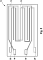
- FIG. 5 shows a sensor element according to another embodiment.
- the same reference numerals designate the same component components as in the FIGS. 1 to 4 ,
- the illustrated sensor element 10 comprises measuring electrodes 14, 16, which are arranged in different layer planes of the sensor element.
- the measuring electrode 14 is preferably provided on a large surface of the sensor element 10 on the ceramic layer 12b, which is made porous in this embodiment and for reasons of clarity in FIG. 5 not shown.
- the measuring electrode 14 is contacted by the contacts 18, 46.
- the further measuring electrode 16 is provided, which via vias, not shown, with the contacts 20, 22 is connected.
- a current flow occurring between the contacts 18, 20 or an electrical resistance of the ceramic layer 12b between these contacts is preferably determined.
- the arranged on the large surface of the sensor element 10 measuring electrode 14 additionally serves as a resistance trace of the heating element 40.
- a suitable heating voltage is applied to the contacts 18, 46 in phases.
- the further measuring electrode 16 preferably serves as a resistance conductor of the temperature measuring element 30.
- the electrical resistance of the measuring electrode 16 at the contacts 20, 22 is determined.
- An alternative mode of operation of the measuring electrodes 14, 16 is to operate both in a first period of time as resistance conductor of a temperature measuring element 30, wherein the measuring electrodes 14, 16 are preferably connected in series by conductive connection of the contacts 22, 46 and the at the contacts 18th , 20 adjacent electrical Total resistance is determined.
- the measuring electrodes 14, 16 are then operated as heating elements, to which a suitable heating voltage is applied to the contacts 18, 46 and 20, 22 in each case.
- the measuring electrodes 14, 16 are either operated in a third period for measuring a particle concentration, wherein an electric current flow or an electrical resistance between the contacts 18, 20 is determined, or the measurement is additionally carried out in the first and second period.
- FIG. 6 a sensor element according to another embodiment is shown.
- the same reference numerals designate the same component components as in the FIGS. 1 to 5 .
- the further measuring electrode 16 of the sensor element 10 is simultaneously designed as a resistance trace of a temperature measuring and a heating element 30, 40.
- these meandering loops 17a, 17b, 17c, 17d, 17e, 17f, 17g, 17h, 17i, 17k, 17l, 17m are formed by firing paths 15a, 15b , 15c, 15d, 15e, 15f, 15g, 15h, 15i, 15k, 15l, 15m, 15n, 15o, 15p, 15q, 15r, 15s, 15t, 15u are bypassed and burned off after preparation of the sensor element via a suitable power supply if required or can be interrupted.
- an electrical resistance between the measuring electrodes 14, 16 at the contacts 18, 20 or 18, 22 is determined to determine particles in the gas mixture and possibly additionally a determination of the temperature by means of a resistance measurement on the contacts 20, 22 performed or a heating voltage to the contacts 20, 46 and 22, 46 applied.
- a section of the further measuring electrode 16 such as, for example, the area between the contacts 20 and 46 or between the contacts 22 and 46, can be made with a larger cross-section or contain a platinum / rhodium alloy, such that a total electrical resistance of these electrode regions results from 10 to 50, in particular 10 ohms.
- the present invention is not applicable to those in FIGS. 1 to 6 illustrated embodiments of a sensor element limited, but it can be made numerous modifications of this sensor element.
- it is possible, for example, to provide additional ceramic layers in the sensor element or to simplify the multi-layer structure of the sensor element in relation to the application, as well as to provide further measuring electrodes.
- the use of several heating and temperature measuring elements is possible.
- the application of the sensor element described is not limited to the determination of soot particles in exhaust gases of internal combustion engines, but it can generally be used to determine the concentration of particles which change the electrical conductivity of a ceramic substrate during storage, for example in chemical manufacturing processes or exhaust aftertreatment systems. Furthermore, the invention can be applied to all ceramic sensor elements which serve to determine gases in gas mixtures and have an integrated temperature measuring element, such as oxygen, nitrogen oxide and ammonia sensors.
Landscapes
- Chemical & Material Sciences (AREA)
- Engineering & Computer Science (AREA)
- Chemical Kinetics & Catalysis (AREA)
- Combustion & Propulsion (AREA)
- Mechanical Engineering (AREA)
- General Engineering & Computer Science (AREA)
- Health & Medical Sciences (AREA)
- Physics & Mathematics (AREA)
- Dispersion Chemistry (AREA)
- Life Sciences & Earth Sciences (AREA)
- Analytical Chemistry (AREA)
- Biochemistry (AREA)
- General Health & Medical Sciences (AREA)
- General Physics & Mathematics (AREA)
- Immunology (AREA)
- Pathology (AREA)
- Investigating Or Analyzing Materials By The Use Of Electric Means (AREA)
Description
- Die Erfindung geht aus von einem Sensorelement zur Bestimmung von Partikeln in Gasgemischen, einem Gassensor dieses enthaltend, sowie deren Verwendung gemäß der im Oberbegriff der unabhängigen Ansprüche definierten Art.
- Um die Funktionstüchtigkeit aktueller in Kraftfahrzeugen eingesetzter Abgasnachbehandlungssysteme zu überprüfen bzw. zu überwachen, werden Sensoren benötigt, mit denen auch im Langzeitbetrieb eine genaue Ermittlung der in einem Verbrennungsabgas vorliegenden Partikelkonzentration ermöglicht werden kann. Darüber hinaus soll mittels derartiger Sensoren eine Beladungsprognose beispielsweise eines in einem Abgassystem vorgesehenen Dieselpartikelfilters ermöglicht werden, um eine hohe Systemsicherheit zu erreichen und dadurch kostengünstigere Filtermaterialien einsetzen zu können.
- Aus der
DE 10 2005 003118 ist ein Sensor zur Detektion von Partikeln in einem Fluidstrom bekannt, der auf der Basis eines keramischen Mehrlagensubstrats ausgeführt ist. Er umfasst zwei voneinander beabstandete Messelektroden, die dem zu untersuchenden Verbrennungsabgas ausgesetzt sind. Lagert sich zwischen den beiden Messelektroden Ruß ab, so kommt es beim Anlegen einer Spannung an die Messelektroden zu einem Stromfluss zwischen den Messelektroden. Ein schichtförmig ausgeführtes Heizelement ermöglicht es, die Elektroden bzw. deren Umgebung auf thermischem Wege von abgelagerten Rußpartikeln zu befreien. Der Sensor umfasst weiterhin ein Temperaturmesselement, mit dem die Temperatur des Sensors detektiert werden kann. Das Heizelement befindet sich innerhalb des Schichtverbundes des Sensors zwischen dem Temperaturmesselement und den Messelektroden. Nachteilig an diesem Aufbau des Sensors ist, dass herkömmliche Temperaturmesselemente keramischer Sensoren Widerstandsleiterbahnen mit einem erhöhten elektrischen Widerstand aufweisen, die nur durch aufwändige Herstellungsverfahren wie beispielsweise Fotofeinstrukturierungsverfahren erzeugt werden können. - Aus der
WO 2005/093233 A1 ist bereits ein Sensorelement für Gassensoren insbesondere zur Bestimmung von Partikeln in Gasgemischen bekannt. Das Sensorelement umfasst des weiteren ein dem zu bestimmenden Gasgemisch ausgesetztes elektrochemisches Messelement mit zwei Messelektroden sowie ein Temperaturmesselement, das an einer beliebigen Stelle im Rußfilterkörper 13 des Partikelfilters angeordnet sein kann. - Aus der
US 4,649,364 A ist bereits ein Feuchtigkeitssensor bekannt, der bifunktional auch die Temperatur bestimmen kann. Dabei kann eine erste Elektrode auch als Temperaturmesselement dienen. Das Temperaturmesselement umfasst dabei eine Widerstandsleiterbahn, die einen elektrischen Widerstand von ca. 100 Ohm bei 0°C aufweist. - Ein Feuchtigkeitssensor mit der Möglichkeit zum Messen der Temperatur ist ebenfalls aus der
JP 57-110948 A US 2003/0196499 A1 ist bereits ein Partikelsensor bekannt, der zusätzlich zu den Messelektroden ein Heizelement sowie ein Temperaturmesselement aufweist. - Aufgabe der vorliegenden Erfindung ist es, ein Sensorelement für Sensoren und ein Verfahren zur Bestimmung der Konzentration von Partikeln in Gasgemischen bereitzustellen, das eine genaue Temperaturregelung gestattet und dennoch kostengünstig hergestellt werden kann.
- Das Sensorelement, der Gassensor bzw. das Verfahren mit den kennzeichnenden Merkmalen der unabhängigen Ansprüche haben den Vorteil, dass die der Erfindung zugrundeliegende Aufgabe in vorteilhafter Weise gelöst wird. Dies beruht insbesondere darauf, dass auf ein Sensorelement mit einfachem Aufbau zurückgegriffen werden kann, wobei ein in das Sensorelement integriertes Temperaturmesselement in einer besonders kostengünstigen Art und Weise realisiert werden kann.
- Da das Temperaturmesselement eine Widerstandsleiterbahn mit relativ geringem elektrischem Widerstand aufweist, kann diese in einfacher Weise erfindungsgemäß mittels der sogenannten Dickschichttechnik auf einem keramischen Substrat des Sensorelementes realisiert werden, während übliche in keramischen Gassensoren realisierte Temperaturmesselemente einen höheren elektrischen Widerstand aufweisen und deren zugrunde liegende Widerstandsleiterbahn aufwändig durch Dünnschichttechnik erzeugt wird.
- Weitere vorteilhafte Ausführungsformen des vorliegenden Sensorelementes, Gassensors bzw. Verfahrens zum Betrieb desselben ergeben sich aus den Unteransprüchen.
- So ist von Vorteil, wenn das Temperaturmesselement eine Widerstandsleiterbahn umfasst, die durch Brennstrecken überbrückte Leiterbahnbereiche aufweist. Dies ermöglicht einen besonders einfachen Abgleich des Temperaturmesselementes nach dessen Herstellung, da eine Unterbrechung der elektrisch leitfähigen Brennstrecken durch Energiezufuhr zu einer faktischen Verlängerung der Widerstandsleiterbahn und somit zu einer Erhöhung von deren Gesamtwiderstand führt.
- Es ist ferner erfindungsgemäß vorgesehen, dass entweder eine der beiden Messelektroden (16) zumindest bereichsweise zusätzlich als Widerstandsleiterbahn des Heizelementes (40) ausgeführt ist und die andere der beiden Messelektroden (14) zumindest bereichsweise zusätzlich als Widerstandsleiterbahn des Temperaturmesselements (30) ausgeführt ist, oder die andere der beiden Messelektroden (14) zumindest bereichsweise zusätzlich als Widerstandsleiterbahn des Temperaturmesselementes (30) und des Heizelementes (40) ausgeführt ist.
- Weiterhin ist von Vorteil, wenn eine Auswertevorrichtung vorgesehen ist, die eine Veränderung des zwischen den Messelektroden des Messelementes anliegenden Stromflusses oder elektrischen Widerstandes unter Berücksichtigung der Messtemperatur ermittelt und das Resultat als Maß für eine Partikelkonzentration oder einen Partikelmassenstrom ausgibt.
- Das Sensorelement bzw. das Verfahren zum Betrieb desselben ist in vorteilhafter Weise geeignet zur Überwachung der Betriebsweise eines Dieselmotors bzw. zur Überprüfung der Funktionstüchtigkeit oder des Beladungszustands eines Partikelfilters.
- Vier Ausführungsbeispiele eines erfindungsgemäßen Sensorelementes sind in der Zeichnung schematisch vereinfacht dargestellt und werden in der nachfolgenden Beschreibung näher erläutert. Dabei zeigt
- Figur Beispiel eines Sensorelements in einer Explosionsdarstellung,
-
Figur 2 eine Beschaltung eines in ein Sensorelement gemäßFigur 1 integriertes Temperaturmesselementes, -
Figur 3 eine Ausschnittsdarstellung eines Sensorelementes gemäß eines Ausführungsbeispiel in einer Aufsicht, -
Figur 4 eine Ausschnittsdarstellung eines Sensorelementes gemäß einer Variante des inFigur 3 dargestellten Ausführungsbeispiels in einer Aufsicht -
Figur 5 eine Ausschnittsdarstellung eines Sensorelementes gemäß eines weiteren Ausführungsbeispiels in einer Aufsicht und -
Figur 6 eine Ausschnittsdarstellung eines Sensorelementes gemäß eines Ausführungsbeispiel in einer Aufsicht. - In
Figur 1 ist ein prinzipieller Aufbau einer Ausführungsform eines Sensorelements dargestellt. Mit 10 ist ein keramisches Sensorelement bezeichnet, das der Bestimmung von Partikeln, wie beispielsweise Rußpartikeln, in einem das Sensorelement umgebenden Gasgemisch dient. Das Sensorelement 10 umfasst beispielsweise eine Mehrzahl von sauerstoffionenleitenden Festelektrolytschichten 11a, 11b und 11c. Die Festelektrolytschichten 11a und 11c werden dabei als keramische Folien ausgeführt und bilden einen planaren keramischen Körper. Sie bestehen vorzugsweise aus einem sauerstoffionenleitenden Festelektrolytmaterial, wie beispielsweise mit Y2O3 stabilisiertem oder teilstabilisiertem ZrO2. - Die Festelektrolytschicht 11b wird dagegen mittels Siebdruck eines pastösen keramischen Materials beispielsweise auf der Festelektrolytschicht 11a erzeugt. Als keramische Komponente des pastösen Materials wird dabei bevorzugt dasselbe Festelektrolytmaterial verwendet, aus dem auch die Festelektrolytschichten 11a, 11c bestehen.
- Weiterhin weist das Sensorelement 10 beispielsweise eine Vielzahl von elektrisch isolierenden keramischen Schichten 12a, 12b, 12c, 12d, 12e und 12f auf. Die Schichten 12a - 12f werden dabei ebenfalls mittels Siebdruck eines pastösen keramischen Materials beispielsweise auf den Festelektrolytschichten 11a, 11c erzeugt. Als keramische Komponente des pastösen Materials wird dabei beispielsweise bariumhaltiges Aluminiumoxid verwendet, da dieses auch bei Temperaturwechselbeanspruchungen über einen langen Zeitraum einen weitgehend konstant hohen elektrischen Widerstand aufweist. Alternativ ist auch die Verwendung von Cerdioxid bzw. der Zusatz anderer Erdalkalioxide möglich.
- Die integrierte Form des planaren keramischen Körpers des Sensorelementes 10 wird durch Zusammenlaminieren der mit der Festelektrolytschicht 11b und mit Funktionsschichten sowie den Schichten 12a - 12f bedruckten keramischen Folien und anschließendem Sintern der laminierten Struktur in an sich bekannter Weise hergestellt.
- Das Sensorelement 10 weist weiterhin ein keramisches Heizelement 40 auf, das in Form einer elektrischen Widerstandsleiterbahn ausgeführt ist und der Aufheizung des Sensorelementes 10 insbesondere auf die Temperatur des zu bestimmenden Gasgemischs bzw. dem Abbrand der auf den Großflächen des Sensorelementes 10 abgelagerten Rußpartikel dient. Die Widerstandsleiterbahn ist weiterhin vorzugsweise in Form eines Mäanders ausgebildet und weist an beiden Enden Durchkontaktierungen 42, 44 sowie elektrische Kontakte 46, 48 auf. Durch Anlegen einer entsprechenden Heizspannung an die Kontakte 46, 48 der Widerstandsleiterbahn kann die Heizleistung des Heizelementes 40 entsprechend reguliert werden. Die Widerstandsleiterbahn sowie die Kontakte 46, 48 bzw. die Durchkontaktierungen 42, 44 sind vorzugsweise aus einem Cermet-Material ausgeführt; vorzugsweise als Mischung von Platin und/oder einem Platinmetall mit keramischen Anteilen, wie beispielsweise Aluminiumoxid.
- Auf einer Großfläche des Sensorelementes 10 sind beispielsweise zwei Messelektroden 14, 16 aufgebracht, die vorzugsweise als ineinander verzahnte Interdigitalelektroden ausgebildet sind und ein elektrochemisches Messelement bilden. Die Verwendung von Interdigitalelektroden als Messelektroden 14, 16 ermöglicht vorteilhafterweise eine besonders genaue Bestimmung des elektrischen Widerstandes bzw. der elektrischen Leitfähigkeit des sich zwischen den Messelektroden 14, 16 befindenden Oberflächenmaterials. Zur Kontaktierung der Messelektroden 14, 16 sind im Bereich eines dem Gasgemisch abgewandten Endes des Sensorelementes Kontakte 18, 20 vorgesehen. Dabei sind die Zuleitungsbereiche der Elektroden 14, 16 vorzugsweise durch die elektrisch isolierende Schicht 12a gegenüber den Einflüssen eines das Sensorelement 10 umgebenden Gasgemischs abgeschirmt. Die Messelektroden 14, 16 weisen beispielsweise einen Elektrodenquerschnitt von 50 bis 150 µm auf. Sie sind, wie beispielsweise auch die Kontakte 18, 20 vorzugsweise aus Platin, Rhodium, einer Platin/Rhodium-Legierung oder einer sonstigen geeigneten elektrisch leitfähigen Legierung ausgeführt. Das Elektrodenmaterial der Messelektroden 14, 16 wird dabei in an sich bekannter Weise als Cermet eingesetzt, um mit den keramischen Folien zu versintern.
- Auf der mit den Messelektroden 14, 16 versehenen Großfläche des Sensorelementes 10 kann zusätzlich eine aus Übersichtlichkeitsgründen nicht dargestellte poröse Deck- oder Schutzschicht vorgesehen sein, die die Messelektroden 14, 16 in ihrem ineinander verzahnten Bereich gegenüber einem direkten Kontakt mit dem zu bestimmenden Gasgemisch abschirmt. Dabei ist die Schichtdicke der porösen Schutzschicht vorzugsweise größer als die Schichtdicke der Messelektroden 14, 16. Die poröse Schutzschicht ist vorzugsweise offenporös ausgeführt, wobei die Porengröße so gewählt wird, dass die zu bestimmenden Partikel im Gasgemisch in die Poren der porösen Schutzschicht eindiffundieren können. Die Porengröße der porösen Schutzschicht liegt dabei vorzugsweise in einem Bereich von 2 bis 10 µm. Die poröse Schutzschicht ist aus einem keramischen Material ausgeführt, das vorzugsweise dem Material der Schicht 12a ähnlich ist oder diesem entspricht und kann mittels Siebdruck hergestellt werden. Die Porosität der porösen Schutzschicht kann durch Zusatz von Porenbildnern zu der Siebdruckpaste entsprechend eingestellt werden.
- Während des Betriebs des Sensorelementes 10 wird an die Messelektroden 14, 16 eine Spannung angelegt. Da die Messelektroden 14, 16 auf der Oberfläche der elektrisch isolierenden Schicht 12b angeordnet sind, kommt es zunächst im wesentlichen zu keinem Stromfluss zwischen den Messelektroden 14, 16.
- Enthält ein das Sensorelement 10 umströmendes Gasgemisch Partikel, insbesondere Ruß, so lagert sich dieser auf der Oberfläche des Sensorelementes 10 ab. Da Ruß eine bestimmte elektrische Leitfähigkeit aufweist, kommt es bei ausreichender Beladung der Oberfläche des Sensorelementes 10 bzw. der porösen Schutzschicht mit Ruß zu einem ansteigenden Stromfluss zwischen den Messelektroden 14, 16, der mit dem Ausmaß der Beladung korreliert.
- Wird nun an die Messelektroden 14, 16 eine vorzugsweise konstante Gleich- oder Wechselspannung angelegt und der zwischen den Messelektroden 14, 16 auftretende Stromfluss bzw. der Anstieg des Stromflusses über der Zeit ermittelt, so kann aus dem Stromfluss bzw. aus dem Differentialquotienten des Stromflusses nach der Zeit auf die abgelagerte Partikelmasse bzw. auf den aktuellen Partikelmassenstrom, insbesondere Rußmassenstrom, und auf die Partikelkonzentration im Gasgemisch geschlossen werden. Alternativ kann anstelle des Stromflusses der elektrische Widerstand bzw. die Impedanz zwischen den Messelektroden 14, 16 berücksichtigt werden. Eine Berechnung des Partikelmassenstromes ist auf der Basis der Messwerte möglich, sofern die Strömungsgeschwindigkeit des Gasgemisches bekannt ist. Diese bzw. der Volumenstrom des Gasgemisches kann bspw. mittels eines geeigneten weiteren Sensors bestimmt werden.
- Darüber hinaus umfasst das Sensorelement 10 ein Temperaturmesselement 30, das in Form einer elektrischen Widerstandsleiterbahn ausgeführt ist. Die Widerstandsleiterbahn ist beispielsweise aus einem ähnlichen oder dem selben Material ausgeführt, wie die Widerstandsleiterbahn des Heizelementes 40. Die Widerstandsleiterbahn des Temperaturmesselementes 30 ist vorzugsweise in Form eines Mäanders ausgeführt, wobei einer der Anschlüsse der Widerstandsleiterbahn vorzugsweise mit dem Kontakt 18 über eine Durchkontaktierung 19 verbunden ist. Ein weiterer elektrischer Anschluss des Temperaturmesselements 30 ist vorzugsweise mit einem weiteren Kontakt 22 über eine weitere Durchkontaktierung 21 leitend verbunden. Durch Anlegen einer entsprechenden Spannung an die Anschlüsse 18, 22 der Widerstandsleiterbahn und durch Bestimmen des elektrischen Widerstandes derselben kann auf die Temperatur des Sensorelementes 10 geschlossen werden.
- Die Widerstandsleiterbahn des Temperaturmesselementes 30 weist dabei einen verhältnismäßig geringen elektrischen Widerstand von bis zu 180 Ohm, insbesondere von 80 bis 120 Ohm bei einer Temperatur von 0°C auf. Üblich ist bei Anwendung in keramischen Gassensoren jedoch die Verwendung von Temperaturmesselementen, deren Widerstandsleiterbahn einen elektrischen Widerstand von mindestens 200 Ohm bei 0°C aufweist. Die Herstellung derartiger Widerstandsleiterbahnen bedingt jedoch spezielle Techniken der Aufbringung des Materials der Widerstandsleiterbahn, wie beispielsweise die sogenannte Dünnschichttechnik, bei der die aufgebrachten Leiterbahnen nachfolgend einer Fotofeinstrukturierung unterzogen werden, um die verhältnismäßig geringen Leiterquerschnitte der Widerstandsleiterbahn realisieren zu können.
- Die Verwendung eines Temperaturmesselementes 30, dessen Widerstandsleiterbahn einen elektrischen Widerstand von weniger als 180 Ohm bei 0°C aufweist, erlaubt eine Herstellung der Widerstandsleiterbahn mittels Dickschichttechnik, beispielsweise durch Siebdruck mit einer das Material der Widerstandsleiterbahn enthaltenden Druckpaste. Da auf gleiche Weise die Widerstandsleiterbahn des Heizelementes 40 realisiert werden kann, ergeben sich so weitere Synergieeffekte.
- So weist die Widerstandsleiterbahn des Temperaturmesselementes 30 beispielsweise einen Leiterbahnquerschnitt von 100 bis 130 µm auf und/oder einen Abstand der einzelnen Mäanderschleifen der Widerstandsleiterbahn von 110 bis 150 µm.
- In
Figur 2 ist exemplarisch die Beschaltung eines in das Sensorelement 10 integrierten Temperaturmesselementes 30 dargestellt. Dabei bildet die Widerstandsleiterbahn des Temperaturmesselementes 30 einen Temperaturmesswiderstand RT, der zusammen mit einem Vorwiderstand RV einen Gesamtwiderstand bildet. An diesem liegt als Betriebsspannung beispielsweise eine an der Motorsteuerung anliegende Spannung UB von beispielsweise 5 V an. Der Temperaturmesswiderstand RT und der Vorwiderstand RV bilden einen Spannungsteiler, dessen Ausgangsspannung die Messspannung UM bildet. Die Messspannung UM kann beispielsweise an einen A/D-Wandler 24 geschaltet werden. Die Messspannung UM dient dabei als Maß für den elektrischen Widerstand des Temperaturmesswiderstandes RT. Das mittels dem A/D-Wandler 24 generierte Signal kann beispielsweise einer nicht dargestellten Auswerteeinheit zugeführt werden, die beispielsweise in einen das Sensorelement 10 enthaltenden Gassensor integriert ist. Der Vorwiderstand RV kann ebenfalls Bestandteil der Auswerteeinheit bzw. des Gassensors sein. - Eine Ausführungsform nach Anspruch 1 ist in
Figur 3 dargestellt, wobei gleiche Bezugszeichen gleiche Bauteilkomponenten bezeichnen wie in denFiguren 1 und 2 . - Das Sensorelement 10 gemäß zweiter Ausführungsform umfasst eine erste Messelektrode 14, die zumindest teilweise gleichzeitig als Widerstandsleiterbahn des Temperaturmesselementes 30 ausgebildet ist. Dazu weist die erste Messelektrode 14 neben dem Kontakt 18 den weiteren Kontakt 22 auf, wobei zur Bestimmung der Temperatur der elektrische Widerstand zwischen den Kontakten 18, 22 herangezogen wird und zur Bestimmung der Partikelbeladung der elektrische Widerstand zwischen den Kontakten 18, 20. Zusätzlich ist die erste Messelektrode 14 zumindest teilweise gleichzeitig als Widerstandsleiterbahn des Heizelementes 40 ausgebildet. Dazu wird zur Beheizung des Sensorelementes 10 eine Heizspannung an die Kontakte 18, 22 angelegt.
- In
Figur 4 ist ein Sensorelement gemäß einer Variante des inFigur 3 dargestellten Sensorelementes abgebildet. Dabei bezeichnen weiterhin gleiche Bezugszeichen gleiche Bauteilkomponenten wie in denFiguren 1 bis 3 . Dabei ist die Anordnung der aus den Messelektroden 14, 16 gebildeten Mäanderstruktur um 90° gedreht vorgesehen, sodass eine größere Anzahl von Mäanderschleifen auf der keramischen Schicht 12b positionierbar sind. -
Figur 5 zeigt ein Sensorelement gemäß eines weiteren Ausführungsbeispiels. Dabei bezeichnen weiterhin gleiche Bezugszeichen gleiche Bauteilkomponenten wie in denFiguren 1 bis 4 . - Das in
Figur 5 abgebildete Sensorelement 10 umfasst Messelektroden 14, 16, die in unterschiedlichen Schichtebenen des Sensorelementes angeordnet sind. Dabei ist beispielsweise die Messelektrode 14 auf einer Großfläche des Sensorelementes 10 vorzugsweise auf der keramischen Schicht 12b vorgesehen, die in diesem Ausführungsbeispiel porös ausgeführt ist und aus Übersichtlichkeitsgründen inFigur 5 nicht dargestellt ist. Die Messelektrode 14 ist durch die Kontakte 18, 46 kontaktiert. In einer weiteren Schichtebene des Sensorelementes 10, vorzugsweise zwischen der keramischen Schichten 12b und einer nicht dargestellten weiteren keramischen Schicht, die zwischen der keramischen Schicht 12b und der Festelektrolytschicht 11a positioniert ist, ist die weitere Messelektrode 16 vorgesehen, die über nicht dargestellte Durchkontaktierungen mit den Kontakten 20, 22 verbunden ist. - Zur Bestimmung von Partikeln in dem zu untersuchenden Gasgemisch wird vorzugsweise ein zwischen den Kontakten 18, 20 auftretender Stromfluss bzw. ein zwischen diesen Kontakten anliegender elektrischer Widerstand der keramischen Schicht 12b bestimmt. Die auf der Großfläche des Sensorelementes 10 angeordnete Messelektrode 14 dient zusätzlich als Widerstandsleiterbahn des Heizelementes 40. Dazu wird an die Kontakte 18, 46 phasenweise eine geeignete Heizspannung angelegt.
- Die weitere Messelektrode 16 dient zusätzlich vorzugsweise als Widerstandsleiterbahn des Temperaturmesselementes 30. Dazu wird der elektrische Widerstand der Messelektrode 16 an den Kontakten 20, 22 bestimmt. Alternativ ist es möglich, die erste Messelektrode 14 als Temperaturmesselement 30 auszuführen und die zweite Messelektrode 16 als Heizelement 40 auszuführen. Weiterhin ist es möglich, mehr als eine Zwischenschicht zwischen den Messelektroden 14, 16 vorzusehen.
- Eine alternative Betriebsweise der Messelektroden 14, 16 besteht darin, beide in einem ersten Zeitraum als Widerstandsleiterbahn eines Temperaturmesselementes 30 zu betreiben, wobei die Messelektroden 14, 16 dabei vorzugsweise durch leitende Verbindung der Kontakte 22, 46 in Reihe geschaltet werden und der an den Kontakten 18, 20 anliegende elektrische Gesamtwiderstand bestimmt wird. In einem zweiten Zeitraum werden die Messelektroden 14, 16 dann als Heizelemente betrieben, wobei dazu an die Kontakte 18, 46 und 20, 22 jeweils eine geeignete Heizspannung angelegt wird. Die Messelektroden 14, 16 werden entweder in einem dritten Zeitraum zur Messung einer Partikelkonzentration betreiben, wobei ein elektrischer Stromfluss bzw. ein elektrischer Widerstand zwischen den Kontakten 18, 20 bestimmt wird, oder die Messung erfolgt zusätzlich im ersten bzw. zweiten Zeitraum.
- In
Figur 6 ist ein Sensorelement gemäß einem weiteren Ausführungsbeispiel dargestellt. Dabei bezeichnen weiterhin gleiche Bezugszeichen gleiche Bauteilkomponenten wie in denFiguren 1 bis 5 . - Gemäß dieser Ausführungsform ist die weitere Messelektrode 16 des Sensorelementes 10 gleichzeitig als Widerstandsleiterbahn eines Temperaturmess- und eines Heizelementes 30, 40 ausgeführt. Um den elektrischen Widerstand der als Widerstandsleiterbahn fungierenden weitere Messelektrode 16 genau einstellen zu können, weist diese Mäanderschleifen 17a, 17b, 17c, 17d, 17e, 17f, 17g, 17h, 17i, 17k, 17l, 17m auf, die durch Brennstrecken 15a, 15b, 15c, 15d, 15e, 15f, 15g, 15h, 15i, 15k, 15l, 15m, 15n, 15o, 15p, 15q, 15r, 15s, 15t, 15u überbrückt sind und nach Herstellung des Sensorelementes über eine geeignete Energiezufuhr bei Bedarf weggebrannt bzw. unterbrochen werden können. Auf diese Weise kann durch Verkürzung der Widerstandsleiterbahn eine Anpassung von deren elektrischem Widerstand auf einen gewünschten Wert erfolgen. Die Anzahl und Ausführung der Mäanderschleifen 17a - 17k sowie deren Ausführung hinsichtlich Länge und Querschnitt ist nicht festgelegt und kann modifiziert werden. Gleiches gilt für die Brennstrecken 15a - 15t.
- Im Betrieb wird dabei zur Bestimmung von Partikeln im Gasgemisch ein elektrischer Widerstand zwischen Messelektroden 14, 16 an den Kontakten 18, 20 bzw. 18, 22 bestimmt sowie ggf. zusätzlich wird eine Bestimmung der Temperatur mittels einer Widerstandsmessung an den Kontakten 20, 22 durchgeführt oder eine Heizspannung an die Kontakte 20, 46 bzw. 22, 46 angelegt. Um eine ausreichende Heizleistung bereitstellen zu können, kann ein Abschnitt der weiteren Messelektrode 16, wie bspw. der Bereich zwischen den Kontakten 20 und 46 bzw. zwischen den Kontakten 22 und 46, mit einem größeren Leitungsquerschnitt ausgeführt sein oder eine Platin-/Rhodiumlegierung enthalten, sodass ein elektrischer Gesamtwiderstand dieser Elektrodenbereiche von 10 bis 50, insbesondere von 10 Ohm resultiert.
- Die vorliegende Erfindung ist nicht auf die in den
Figuren 1 bis 6 dargestellten Ausführungsformen eines Sensorelementes beschränkt, sondern es können zahlreiche Abwandlungen dieses Sensorelementes vorgenommen werden. So ist es beispielsweise möglich, zusätzliche keramische Schichten im Sensorelement vorzusehen oder den Mehrschichtaufbau des Sensorelementes anwendungsbezogen zu vereinfachen, sowie weitere Messelektroden vorzusehen. Auch die Verwendung mehrerer Heiz- und Temperaturmesselemente ist möglich. - Die Anwendung des beschriebenen Sensorelementes ist nicht auf die Bestimmung von Rußpartikeln in Abgasen von Verbrennungsmotoren beschränkt, sondern es kann allgemein zur Bestimmung der Konzentration von Partikeln, die die elektrische Leitfähigkeit eines keramischen Substrats bei Einlagerung verändern, beispielsweise in chemischen Herstellungsprozessen oder Abluftnachbehandlungsanlagen, eingesetzt werden. Weiterhin kann die Erfindung auf alle keramischen Sensorelemente übertragen werden, die der Bestimmung von Gasen in Gasgemischen dienen und ein integriertes Temperaturmesselement aufweisen, wie Sauerstoff-, Stickoxid- und Ammoniaksensoren.
Claims (6)
- Sensorelement für Gassensoren zur Bestimmung von Partikeln in Gasgemischen, mit mindestens einem dem zu bestimmenden Gasgemisch aussetzbaren resistiven Messelement mit zwei Messelektroden (14, 16) und mindestens einem in das Sensorelement integrierten Temperaturmesselement (30), wobei in dem Sensorelement ein Heizelement (40) vorgesehen ist, dadurch gekennzeichnet, dass entweder eine der beiden Messelektroden (16) zumindest bereichsweise zusätzlich als Widerstandsleiterbahn des Heizelementes (40) ausgeführt ist und die andere der beiden Messelektroden (14) zumindest bereichsweise zusätzlich als Widerstandsleiterbahn des Temperaturmesselements (30) ausgeführt ist, oder eine der beiden Messelektroden (14) zumindest bereichsweise zusätzlich als Widerstandsleiterbahn des Temperaturmesselementes (30) und des Heizelementes (40) ausgeführt ist, und dass in beiden Fällen die Widerstandsleiterbahn des Temperaturmesselements (30) einen elektrischen Widerstand von weniger als 180 Ohm bei 0°C aufweist und mittels Dickschichttechnik auf einem keramischen Substrat des Sensorelements realisiert ist.
- Sensorelement nach Anspruch 1, dadurch gekennzeichnet, dass die Widerstandsleiterbahn des Temperaturmesselementes (30) durch Brennstrecken (15a - 15u) überbrückte Leiterbahnbereiche (17a - 17k) aufweist.
- Sensorelement nach einem der Anspruch 1 oder 2, dadurch gekennzeichnet, dass die Messelektroden (14, 16) als Interdigitalelektroden ausgeführt sind.
- Sensorelement nach einem der vorhergehenden Ansprüche, dadurch gekennzeichnet, dass die Messelektroden (14, 16) in unterschiedlichen Schichtebenen (12c, 12d) des Sensorelementes angeordnet sind.
- Gassensor zur Bestimmung von Partikeln in Gasgemischen, insbesondere Rußsensor, mit einem Sensorelement nach einem der Ansprüche 1 bis 5, dadurch gekennzeichnet, dass eine Auswerteeinheit enthalten ist, in der eine Korrelation zwischen einer herrschenden Messtemperatur und einem mittels dem Sensorelement zwischen Messelektroden (14, 16) des Sensorelementes bestimmten Stromfluss oder elektrischen Widerstand in Abhängigkeit von der Partikelbeladung hinterlegt ist.
- Verwendung eines Sensorelementes nach einem der Ansprüche 1 bis 5 oder eines Gassensors nach Anspruch 6 zur Überwachung der Betriebsweise eines Dieselmotors oder der Funktionstüchtigkeit und/oder des Beladungszustands eines Partikelfilters.
Applications Claiming Priority (2)
| Application Number | Priority Date | Filing Date | Title |
|---|---|---|---|
| DE102005053120A DE102005053120A1 (de) | 2005-11-08 | 2005-11-08 | Sensorelement für Gassensoren und Verfahren zum Betrieb desselben |
| PCT/EP2006/067608 WO2007054424A1 (de) | 2005-11-08 | 2006-10-20 | Sensorelement für gassensoren und verfahren zum betrieb desselben |
Publications (2)
| Publication Number | Publication Date |
|---|---|
| EP1949072A1 EP1949072A1 (de) | 2008-07-30 |
| EP1949072B1 true EP1949072B1 (de) | 2018-07-25 |
Family
ID=37562082
Family Applications (1)
| Application Number | Title | Priority Date | Filing Date |
|---|---|---|---|
| EP06807427.7A Not-in-force EP1949072B1 (de) | 2005-11-08 | 2006-10-20 | Sensorelement für gassensoren und verfahren zum betrieb desselben |
Country Status (4)
| Country | Link |
|---|---|
| US (1) | US8182665B2 (de) |
| EP (1) | EP1949072B1 (de) |
| DE (1) | DE102005053120A1 (de) |
| WO (1) | WO2007054424A1 (de) |
Families Citing this family (60)
| Publication number | Priority date | Publication date | Assignee | Title |
|---|---|---|---|---|
| DE102007021913A1 (de) * | 2007-05-10 | 2008-11-20 | Robert Bosch Gmbh | Verfahren und Sensor zur Detektion von Teilchen in einem Gasstrom sowie deren Verwendung |
| DE102007047081A1 (de) | 2007-10-01 | 2009-04-02 | Robert Bosch Gmbh | Verfahren zur Detektion eines Vergiftungsgrads eines Partikelsensors und Partikelsensor |
| FR2922309A1 (fr) * | 2007-10-15 | 2009-04-17 | Peugeot Citroen Automobiles Sa | Dispositif de detection et de mesure d'emissions de particules embarque dans une ligne d'echappement d'un vehicule automobile |
| WO2009108091A1 (en) * | 2008-02-27 | 2009-09-03 | Volvo Technology Corporation | Method and arrangement for detecting particles |
| DE102009007126A1 (de) * | 2009-02-02 | 2010-08-12 | Continental Automotive Gmbh | Verfahren und Vorrichtung zur Messung der Rußbeladung in Abgassystemen von Dieselmotoren |
| DE102009049669A1 (de) * | 2009-10-16 | 2011-04-21 | Continental Automotive Gmbh | Verfahren zur Zustandsbewertung eines Rußsensors in einem Kraftfahrzeug |
| JP5163663B2 (ja) | 2010-01-29 | 2013-03-13 | トヨタ自動車株式会社 | 微粒子検知用センサ及び微粒子検知装置 |
| WO2011106625A1 (en) * | 2010-02-25 | 2011-09-01 | Stoneridge, Inc. | Soot sensor system |
| JP5214651B2 (ja) * | 2010-03-02 | 2013-06-19 | 日本特殊陶業株式会社 | ガスセンサ素子、ガスセンサおよびガスセンサの制御システム |
| DE102010011635B4 (de) * | 2010-03-16 | 2012-01-05 | Continental Automotive Gmbh | Betriebsverfahren eines Rußsensors mit einer Kammstruktur |
| DE102010011639A1 (de) * | 2010-03-16 | 2011-09-22 | Continental Automotive Gmbh | Rußsensor, Herstellungsverfahren eines Rußsensors sowie Betriebsverfahren eines Rußsensors |
| JP2011247650A (ja) * | 2010-05-24 | 2011-12-08 | Denso Corp | 粒子状物質検出センサ、及び粒子状物質検出センサユニット |
| JP5531849B2 (ja) | 2010-08-06 | 2014-06-25 | 株式会社デンソー | センサ制御装置 |
| JP5201194B2 (ja) * | 2010-10-28 | 2013-06-05 | 株式会社デンソー | 粒子状物質検出装置及び粒子状物質検出素子の製造方法 |
| US8928338B2 (en) * | 2010-11-17 | 2015-01-06 | Delphi Technologies, Inc. | Self diagnostics of a particulate matter sensor |
| DE102010054669A1 (de) | 2010-12-15 | 2012-06-21 | Continental Automotive Gmbh | Sensorvorrichtung |
| US9062576B2 (en) | 2010-12-22 | 2015-06-23 | Caterpillar Inc. | Exhaust particulate filter system and operating method therefor |
| EP2715371B1 (de) * | 2011-05-26 | 2019-03-27 | Stoneridge, Inc. | Russsensorsystem |
| EP2752658B1 (de) * | 2011-08-29 | 2016-09-28 | Toyota Jidosha Kabushiki Kaisha | Mikropartikelsensor und verfahren zur herstellung eines mikropartikelsensors |
| WO2013133849A1 (en) * | 2012-03-09 | 2013-09-12 | International Engine Intellectual Property Company, Llc | Trapped soot measurement |
| DE102012207761A1 (de) * | 2012-05-09 | 2013-11-14 | Continental Automotive Gmbh | Sensorelement |
| DE102012217428A1 (de) * | 2012-09-26 | 2014-03-27 | Robert Bosch Gmbh | Sensor zur Detektion von Teilchen |
| JP2014118968A (ja) * | 2012-12-17 | 2014-06-30 | Hyundai Motor Company Co Ltd | 粒子状物質センサーユニット |
| DE102013202980A1 (de) * | 2013-02-22 | 2014-08-28 | Robert Bosch Gmbh | Verfahren und Vorrichtung zur Regeneration eines Partikelsensors |
| DE102013110291A1 (de) | 2013-03-06 | 2014-09-11 | Heraeus Sensor Technology Gmbh | Verfahren zur Herstellung eines Rußsensors mit einem Laserstrahl |
| FR3011331B1 (fr) * | 2013-10-01 | 2017-02-17 | Univ Aix Marseille | Capteur a gaz a couche sensible chauffee |
| US9234805B2 (en) | 2013-10-31 | 2016-01-12 | Cummins Ip, Inc. | Temperature compensation for particulate matter sensor regeneration |
| DE202013010565U1 (de) * | 2013-11-22 | 2014-11-24 | Seuffer gmbH & Co. KG | Tankmodul für einen Flüssigkeitstank |
| JP6255244B2 (ja) * | 2014-01-08 | 2017-12-27 | 日本特殊陶業株式会社 | 微粒子センサ |
| JP6228018B2 (ja) * | 2014-01-10 | 2017-11-08 | 株式会社Soken | 粒子状物質検出素子、粒子状物質検出センサ並びに粒子状物質検出素子の製造方法 |
| JP6435198B2 (ja) * | 2015-01-07 | 2018-12-05 | 株式会社Soken | 粒子状物質検出センサ |
| JP6441161B2 (ja) * | 2015-04-28 | 2018-12-19 | 株式会社デンソー | 粒子状物質検出センサ |
| KR101652981B1 (ko) * | 2015-05-06 | 2016-09-06 | 주식회사 코멧네트워크 | 입자상 물질 센서 |
| WO2016200132A1 (ko) * | 2015-06-09 | 2016-12-15 | 주식회사 아모텍 | 입자상 물질 센서 및 이를 포함하는 배기가스 정화 시스템 |
| JP6409714B2 (ja) * | 2015-06-30 | 2018-10-24 | 株式会社デンソー | 粒子状物質検出システム |
| WO2017090434A1 (ja) * | 2015-11-25 | 2017-06-01 | 京セラ株式会社 | センサ基板およびセンサ装置 |
| DE102015226352A1 (de) * | 2015-12-21 | 2017-06-22 | Robert Bosch Gmbh | Partikelsensor |
| KR101990497B1 (ko) * | 2016-03-31 | 2019-06-19 | 주식회사 아모텍 | 입자상 물질 센서 |
| KR101761185B1 (ko) | 2016-04-27 | 2017-07-28 | 주식회사 코멧네트워크 | 입자상 물질 센서 |
| EP3444596B1 (de) * | 2016-05-20 | 2020-03-04 | Kyocera Corporation | Sensorplatine und sensorvorrichtung |
| DE102016221372A1 (de) | 2016-10-28 | 2018-05-03 | Robert Bosch Gmbh | Sensorelement zur Bestimmung von Partikeln in einem fluiden Medium |
| DE102017205064A1 (de) | 2016-12-28 | 2018-06-28 | Robert Bosch Gmbh | Sensorelement zur Erfassung mindestens einer Eigenschaft eines Messgases in einem Messgasraum |
| DE102017205158A1 (de) | 2017-03-27 | 2018-09-27 | Robert Bosch Gmbh | Verfahren zur Herstellung eines Sensorelements |
| DE102017217637A1 (de) | 2017-04-20 | 2018-10-25 | Robert Bosch Gmbh | Keramisches Sensorelement für einen Abgassensor |
| DE102017207781A1 (de) * | 2017-05-09 | 2018-11-15 | Robert Bosch Gmbh | Sensorelement zur Erfassung von Partikeln eines Messgases in einem Messgasraum |
| DE102017208568A1 (de) | 2017-05-19 | 2018-11-22 | Robert Bosch Gmbh | Verfahren zur Bestimmung der Temperatur eines Abgassensors |
| DE102017209392A1 (de) | 2017-06-02 | 2018-12-06 | Robert Bosch Gmbh | Sensorelement zur Erfassung von Partikeln eines Messgases in einem Messgasraum |
| DE102017214621A1 (de) | 2017-08-22 | 2019-02-28 | Robert Bosch Gmbh | Verfahren zum Betreiben eines Sensors zum Nachweis von Rußpartikeln |
| DE102018212863A1 (de) | 2017-09-26 | 2019-03-28 | Robert Bosch Gmbh | Sensoranordnung zur Erfassung von Partikeln eines Messgases in einem Messgasraum und Verfahren zur Erfassung von Partikeln eines Messgases in einem Messgasraum |
| DE102017219429A1 (de) | 2017-10-30 | 2019-05-02 | Robert Bosch Gmbh | Sensorelement zur Erfassung von Partikeln eines Messgases in einem Messgasraum |
| DE102018207784A1 (de) | 2017-12-19 | 2019-06-19 | Robert Bosch Gmbh | Sensoranordnung zur Erfassung von Partikeln eines Messgases in einem Messgasraum und Verfahren zur Erfassung von Partikeln eines Messgases in einem Messgasraum |
| DE102018207793A1 (de) | 2017-12-19 | 2019-06-19 | Robert Bosch Gmbh | Verfahren zur Erfassung von Partikeln eines Messgases in einem Messgasraum und Sensoranordnung zur Erfassung von Partikeln eines Messgases in einem Messgasraum |
| DE102018207789A1 (de) | 2017-12-19 | 2019-06-19 | Robert Bosch Gmbh | Sensoranordnung zur Erfassung von Partikeln eines Messgases in einem Messgasraum und Verfahren zur Erfassung von Partikeln eines Messgases in einem Messgasraum |
| CN108020494A (zh) * | 2017-12-26 | 2018-05-11 | 中国科学院合肥物质科学研究院 | 一种耐温型高灵敏度电容式碳尘pm快速测量装置及方法 |
| EP3550295B1 (de) * | 2018-04-05 | 2022-07-13 | Alpha M.O.S. | Gassensor mit einem konfigurierbaren heizelement und verfahren unter ausnutzung der konfigurierbarkeit |
| CN110095395A (zh) * | 2019-06-03 | 2019-08-06 | 深圳市森世泰科技有限公司 | 用于气体颗粒物浓度测量的芯片、传感器及测量方法 |
| DE102019211483A1 (de) | 2019-08-01 | 2021-02-04 | Robert Bosch Gmbh | Sensorelement zur Erfassung von Partikeln eines Messgases in einem Messgasraum |
| CN114323660B (zh) * | 2022-01-10 | 2023-09-26 | 中车大连机车车辆有限公司 | 一种低误报率碾瓦位置可视的高效柴油机碾瓦报警装置 |
| CN117167125A (zh) * | 2022-05-25 | 2023-12-05 | 上汽通用汽车有限公司 | 传感器、发动机系统及车辆 |
| DE102023113839A1 (de) * | 2023-05-25 | 2024-11-28 | Endress+Hauser Conducta Gmbh+Co. Kg | Sensorelement, konduktiver Leitfähigkeitssensor und Verfahren zum Ermitteln einer Leitfähigkeit eines Messmediums |
Citations (3)
| Publication number | Priority date | Publication date | Assignee | Title |
|---|---|---|---|---|
| US4656832A (en) * | 1982-09-30 | 1987-04-14 | Nippondenso Co., Ltd. | Detector for particulate density and filter with detector for particulate density |
| WO1991001561A1 (de) * | 1989-07-25 | 1991-02-07 | Roth-Technik Gmbh & Co. Forschung Für Automobil- Und Umwelttechnik | Temperatursensor und verfahren zu seiner herstellung |
| US20020118027A1 (en) * | 2000-10-24 | 2002-08-29 | Dmitri Routkevitch | Nanostructured ceramic platform for micromachined devices and device arrays |
Family Cites Families (8)
| Publication number | Priority date | Publication date | Assignee | Title |
|---|---|---|---|---|
| JPS57110948A (en) * | 1980-12-27 | 1982-07-10 | Toshiba Corp | Moisture sensing element |
| JPS6066145A (ja) | 1983-09-20 | 1985-04-16 | Omron Tateisi Electronics Co | 外部雰囲気検知装置 |
| DE19851966A1 (de) * | 1998-11-11 | 2000-05-18 | Bosch Gmbh Robert | Keramisches Schichtsystem und Verfahren zur Herstellung einer keramischen Heizeinrichtung |
| US6634210B1 (en) * | 2002-04-17 | 2003-10-21 | Delphi Technologies, Inc. | Particulate sensor system |
| DE10331838B3 (de) * | 2003-04-03 | 2004-09-02 | Georg Bernitz | Sensorelement, Verfahren zu seiner Herstellung und Verfahren zur Erfassung von Partikeln |
| KR100505018B1 (ko) | 2003-06-30 | 2005-07-28 | 주식회사 효성 | 고강력 폴리에틸렌-2,6-나프탈레이트 섬유 및 이의 제조방법 |
| US20080048681A1 (en) * | 2004-02-12 | 2008-02-28 | Daimlerchrysler Ag | Device for Determining the State of a Soot Particle Filter |
| WO2006077197A1 (de) * | 2005-01-21 | 2006-07-27 | Robert Bosch Gmbh | Sensorelement für partikelsensoren und verfahren zum betrieb desselben |
-
2005
- 2005-11-08 DE DE102005053120A patent/DE102005053120A1/de not_active Withdrawn
-
2006
- 2006-10-20 US US12/084,675 patent/US8182665B2/en not_active Expired - Fee Related
- 2006-10-20 WO PCT/EP2006/067608 patent/WO2007054424A1/de not_active Ceased
- 2006-10-20 EP EP06807427.7A patent/EP1949072B1/de not_active Not-in-force
Patent Citations (3)
| Publication number | Priority date | Publication date | Assignee | Title |
|---|---|---|---|---|
| US4656832A (en) * | 1982-09-30 | 1987-04-14 | Nippondenso Co., Ltd. | Detector for particulate density and filter with detector for particulate density |
| WO1991001561A1 (de) * | 1989-07-25 | 1991-02-07 | Roth-Technik Gmbh & Co. Forschung Für Automobil- Und Umwelttechnik | Temperatursensor und verfahren zu seiner herstellung |
| US20020118027A1 (en) * | 2000-10-24 | 2002-08-29 | Dmitri Routkevitch | Nanostructured ceramic platform for micromachined devices and device arrays |
Also Published As
| Publication number | Publication date |
|---|---|
| DE102005053120A1 (de) | 2007-05-10 |
| US20090217737A1 (en) | 2009-09-03 |
| EP1949072A1 (de) | 2008-07-30 |
| US8182665B2 (en) | 2012-05-22 |
| WO2007054424A1 (de) | 2007-05-18 |
Similar Documents
| Publication | Publication Date | Title |
|---|---|---|
| EP1949072A1 (de) | Sensorelement für gassensoren und verfahren zum betrieb desselben | |
| EP1844316B1 (de) | Sensorelement für partikelsensoren und verfahren zum betrieb desselben | |
| DE102017006165B4 (de) | Verfahren zur bestimmung einer verschlechterung eines katalysators | |
| DE102017010315A1 (de) | Verfahren zur verminderung einer ausgabeverschlechterung eines gassensors | |
| EP1869428B1 (de) | Sensorelement für partikelsensoren und verfahren zum betrieb desselben | |
| EP1792170A1 (de) | Sensorelement für partikelsensoren und verfahren zum betrieb desselben | |
| EP2130025A2 (de) | Sensorelement zur bestimmung von partikeln in einem messgas | |
| DE102008044374A1 (de) | Sensorelement und Verfahren zur Bestimmung von Gaskomponenten in Gasgemischen sowie deren Verwendung | |
| EP2082220B1 (de) | Verfahren und verwendung des verfahrens zur bestimmung der partikel- und gaskonzentration eines gasgemisches | |
| DE102016224771A1 (de) | Gassensor Diagnostizierungsverfahren | |
| DE102018005701A1 (de) | Gassensor-Kalibrier-Verfahren | |
| DE102007021913A1 (de) | Verfahren und Sensor zur Detektion von Teilchen in einem Gasstrom sowie deren Verwendung | |
| DE102017005381A1 (de) | Gassensor | |
| DE102004043122A1 (de) | Sensorelement für Partikelsensoren und Verfahren zur Herstellung desselben | |
| DE102019001574A1 (de) | Gassensor | |
| DE102006002111A1 (de) | Sensorelement für Partikelsensoren und Verfahren zum Betrieb desselben | |
| EP1875198A1 (de) | Sensorelement für partikelsensoren und verfahren zum betrieb desselben | |
| EP1858904A1 (de) | Sensorelement und sensor dieses enthaltend | |
| EP1844315B1 (de) | Messanordnung und verfahren zur bestimmung der konzentration von partikeln in gasgemischen | |
| DE102005021131A1 (de) | Sensorelement für Gassensoren | |
| DE102006002112B4 (de) | Verfahren zur Bestimmung der Konzentration von Partikeln in Gasgemischen | |
| EP2269047A1 (de) | Beheizte sprungsonde mit vereinfachter elektrischer kontaktierung | |
| DE102014211752A1 (de) | Verfahren zum Betrieb eines Partikelsensors | |
| WO2003056323A1 (de) | Abgassonde | |
| DE102008040993A1 (de) | Sensorelement eines Gassensors und Verwendung desselben |
Legal Events
| Date | Code | Title | Description |
|---|---|---|---|
| PUAI | Public reference made under article 153(3) epc to a published international application that has entered the european phase |
Free format text: ORIGINAL CODE: 0009012 |
|
| 17P | Request for examination filed |
Effective date: 20080609 |
|
| AK | Designated contracting states |
Kind code of ref document: A1 Designated state(s): AT BE BG CH CY CZ DE DK EE ES FI FR GB GR HU IE IS IT LI LT LU LV MC NL PL PT RO SE SI SK TR |
|
| 17Q | First examination report despatched |
Effective date: 20090205 |
|
| DAX | Request for extension of the european patent (deleted) | ||
| RIC1 | Information provided on ipc code assigned before grant |
Ipc: G01N 27/04 20060101ALI20160810BHEP Ipc: G01N 15/06 20060101AFI20160810BHEP Ipc: F01N 11/00 20060101ALI20160810BHEP Ipc: F01N 9/00 20060101ALI20160810BHEP |
|
| GRAP | Despatch of communication of intention to grant a patent |
Free format text: ORIGINAL CODE: EPIDOSNIGR1 |
|
| INTG | Intention to grant announced |
Effective date: 20180424 |
|
| GRAS | Grant fee paid |
Free format text: ORIGINAL CODE: EPIDOSNIGR3 |
|
| GRAA | (expected) grant |
Free format text: ORIGINAL CODE: 0009210 |
|
| AK | Designated contracting states |
Kind code of ref document: B1 Designated state(s): AT BE BG CH CY CZ DE DK EE ES FI FR GB GR HU IE IS IT LI LT LU LV MC NL PL PT RO SE SI SK TR |
|
| REG | Reference to a national code |
Ref country code: GB Ref legal event code: FG4D Free format text: NOT ENGLISH |
|
| REG | Reference to a national code |
Ref country code: CH Ref legal event code: EP |
|
| REG | Reference to a national code |
Ref country code: AT Ref legal event code: REF Ref document number: 1022282 Country of ref document: AT Kind code of ref document: T Effective date: 20180815 |
|
| REG | Reference to a national code |
Ref country code: DE Ref legal event code: R096 Ref document number: 502006015971 Country of ref document: DE |
|
| REG | Reference to a national code |
Ref country code: IE Ref legal event code: FG4D Free format text: LANGUAGE OF EP DOCUMENT: GERMAN |
|
| REG | Reference to a national code |
Ref country code: FR Ref legal event code: PLFP Year of fee payment: 13 |
|
| REG | Reference to a national code |
Ref country code: NL Ref legal event code: MP Effective date: 20180725 |
|
| REG | Reference to a national code |
Ref country code: LT Ref legal event code: MG4D |
|
| PG25 | Lapsed in a contracting state [announced via postgrant information from national office to epo] |
Ref country code: NL Free format text: LAPSE BECAUSE OF FAILURE TO SUBMIT A TRANSLATION OF THE DESCRIPTION OR TO PAY THE FEE WITHIN THE PRESCRIBED TIME-LIMIT Effective date: 20180725 |
|
| PG25 | Lapsed in a contracting state [announced via postgrant information from national office to epo] |
Ref country code: PL Free format text: LAPSE BECAUSE OF FAILURE TO SUBMIT A TRANSLATION OF THE DESCRIPTION OR TO PAY THE FEE WITHIN THE PRESCRIBED TIME-LIMIT Effective date: 20180725 Ref country code: IS Free format text: LAPSE BECAUSE OF FAILURE TO SUBMIT A TRANSLATION OF THE DESCRIPTION OR TO PAY THE FEE WITHIN THE PRESCRIBED TIME-LIMIT Effective date: 20181125 Ref country code: LT Free format text: LAPSE BECAUSE OF FAILURE TO SUBMIT A TRANSLATION OF THE DESCRIPTION OR TO PAY THE FEE WITHIN THE PRESCRIBED TIME-LIMIT Effective date: 20180725 Ref country code: SE Free format text: LAPSE BECAUSE OF FAILURE TO SUBMIT A TRANSLATION OF THE DESCRIPTION OR TO PAY THE FEE WITHIN THE PRESCRIBED TIME-LIMIT Effective date: 20180725 Ref country code: BG Free format text: LAPSE BECAUSE OF FAILURE TO SUBMIT A TRANSLATION OF THE DESCRIPTION OR TO PAY THE FEE WITHIN THE PRESCRIBED TIME-LIMIT Effective date: 20181025 Ref country code: FI Free format text: LAPSE BECAUSE OF FAILURE TO SUBMIT A TRANSLATION OF THE DESCRIPTION OR TO PAY THE FEE WITHIN THE PRESCRIBED TIME-LIMIT Effective date: 20180725 Ref country code: GR Free format text: LAPSE BECAUSE OF FAILURE TO SUBMIT A TRANSLATION OF THE DESCRIPTION OR TO PAY THE FEE WITHIN THE PRESCRIBED TIME-LIMIT Effective date: 20181026 |
|
| PG25 | Lapsed in a contracting state [announced via postgrant information from national office to epo] |
Ref country code: ES Free format text: LAPSE BECAUSE OF FAILURE TO SUBMIT A TRANSLATION OF THE DESCRIPTION OR TO PAY THE FEE WITHIN THE PRESCRIBED TIME-LIMIT Effective date: 20180725 Ref country code: LV Free format text: LAPSE BECAUSE OF FAILURE TO SUBMIT A TRANSLATION OF THE DESCRIPTION OR TO PAY THE FEE WITHIN THE PRESCRIBED TIME-LIMIT Effective date: 20180725 |
|
| REG | Reference to a national code |
Ref country code: DE Ref legal event code: R097 Ref document number: 502006015971 Country of ref document: DE |
|
| PG25 | Lapsed in a contracting state [announced via postgrant information from national office to epo] |
Ref country code: RO Free format text: LAPSE BECAUSE OF FAILURE TO SUBMIT A TRANSLATION OF THE DESCRIPTION OR TO PAY THE FEE WITHIN THE PRESCRIBED TIME-LIMIT Effective date: 20180725 Ref country code: CZ Free format text: LAPSE BECAUSE OF FAILURE TO SUBMIT A TRANSLATION OF THE DESCRIPTION OR TO PAY THE FEE WITHIN THE PRESCRIBED TIME-LIMIT Effective date: 20180725 Ref country code: EE Free format text: LAPSE BECAUSE OF FAILURE TO SUBMIT A TRANSLATION OF THE DESCRIPTION OR TO PAY THE FEE WITHIN THE PRESCRIBED TIME-LIMIT Effective date: 20180725 |
|
| PG25 | Lapsed in a contracting state [announced via postgrant information from national office to epo] |
Ref country code: SK Free format text: LAPSE BECAUSE OF FAILURE TO SUBMIT A TRANSLATION OF THE DESCRIPTION OR TO PAY THE FEE WITHIN THE PRESCRIBED TIME-LIMIT Effective date: 20180725 Ref country code: DK Free format text: LAPSE BECAUSE OF FAILURE TO SUBMIT A TRANSLATION OF THE DESCRIPTION OR TO PAY THE FEE WITHIN THE PRESCRIBED TIME-LIMIT Effective date: 20180725 |
|
| PLBE | No opposition filed within time limit |
Free format text: ORIGINAL CODE: 0009261 |
|
| REG | Reference to a national code |
Ref country code: CH Ref legal event code: PL |
|
| STAA | Information on the status of an ep patent application or granted ep patent |
Free format text: STATUS: NO OPPOSITION FILED WITHIN TIME LIMIT |
|
| REG | Reference to a national code |
Ref country code: BE Ref legal event code: MM Effective date: 20181031 |
|
| PG25 | Lapsed in a contracting state [announced via postgrant information from national office to epo] |
Ref country code: MC Free format text: LAPSE BECAUSE OF FAILURE TO SUBMIT A TRANSLATION OF THE DESCRIPTION OR TO PAY THE FEE WITHIN THE PRESCRIBED TIME-LIMIT Effective date: 20180725 Ref country code: LU Free format text: LAPSE BECAUSE OF NON-PAYMENT OF DUE FEES Effective date: 20181020 |
|
| 26N | No opposition filed |
Effective date: 20190426 |
|
| REG | Reference to a national code |
Ref country code: IE Ref legal event code: MM4A |
|
| PG25 | Lapsed in a contracting state [announced via postgrant information from national office to epo] |
Ref country code: BE Free format text: LAPSE BECAUSE OF NON-PAYMENT OF DUE FEES Effective date: 20181031 Ref country code: CH Free format text: LAPSE BECAUSE OF NON-PAYMENT OF DUE FEES Effective date: 20181031 Ref country code: SI Free format text: LAPSE BECAUSE OF FAILURE TO SUBMIT A TRANSLATION OF THE DESCRIPTION OR TO PAY THE FEE WITHIN THE PRESCRIBED TIME-LIMIT Effective date: 20180725 Ref country code: LI Free format text: LAPSE BECAUSE OF NON-PAYMENT OF DUE FEES Effective date: 20181031 |
|
| PG25 | Lapsed in a contracting state [announced via postgrant information from national office to epo] |
Ref country code: IE Free format text: LAPSE BECAUSE OF NON-PAYMENT OF DUE FEES Effective date: 20181020 |
|
| REG | Reference to a national code |
Ref country code: AT Ref legal event code: MM01 Ref document number: 1022282 Country of ref document: AT Kind code of ref document: T Effective date: 20181020 |
|
| PG25 | Lapsed in a contracting state [announced via postgrant information from national office to epo] |
Ref country code: AT Free format text: LAPSE BECAUSE OF NON-PAYMENT OF DUE FEES Effective date: 20181020 |
|
| PG25 | Lapsed in a contracting state [announced via postgrant information from national office to epo] |
Ref country code: TR Free format text: LAPSE BECAUSE OF FAILURE TO SUBMIT A TRANSLATION OF THE DESCRIPTION OR TO PAY THE FEE WITHIN THE PRESCRIBED TIME-LIMIT Effective date: 20180725 |
|
| PG25 | Lapsed in a contracting state [announced via postgrant information from national office to epo] |
Ref country code: PT Free format text: LAPSE BECAUSE OF FAILURE TO SUBMIT A TRANSLATION OF THE DESCRIPTION OR TO PAY THE FEE WITHIN THE PRESCRIBED TIME-LIMIT Effective date: 20180725 |
|
| PG25 | Lapsed in a contracting state [announced via postgrant information from national office to epo] |
Ref country code: HU Free format text: LAPSE BECAUSE OF FAILURE TO SUBMIT A TRANSLATION OF THE DESCRIPTION OR TO PAY THE FEE WITHIN THE PRESCRIBED TIME-LIMIT; INVALID AB INITIO Effective date: 20061020 Ref country code: CY Free format text: LAPSE BECAUSE OF FAILURE TO SUBMIT A TRANSLATION OF THE DESCRIPTION OR TO PAY THE FEE WITHIN THE PRESCRIBED TIME-LIMIT Effective date: 20180725 |
|
| PGFP | Annual fee paid to national office [announced via postgrant information from national office to epo] |
Ref country code: GB Payment date: 20231025 Year of fee payment: 18 |
|
| PGFP | Annual fee paid to national office [announced via postgrant information from national office to epo] |
Ref country code: IT Payment date: 20231031 Year of fee payment: 18 Ref country code: FR Payment date: 20231023 Year of fee payment: 18 |
|
| REG | Reference to a national code |
Ref country code: DE Ref legal event code: R084 Ref document number: 502006015971 Country of ref document: DE |
|
| PGFP | Annual fee paid to national office [announced via postgrant information from national office to epo] |
Ref country code: DE Payment date: 20231218 Year of fee payment: 18 |
|
| REG | Reference to a national code |
Ref country code: DE Ref legal event code: R119 Ref document number: 502006015971 Country of ref document: DE |
|
| GBPC | Gb: european patent ceased through non-payment of renewal fee |
Effective date: 20241020 |
|
| PG25 | Lapsed in a contracting state [announced via postgrant information from national office to epo] |
Ref country code: DE Free format text: LAPSE BECAUSE OF NON-PAYMENT OF DUE FEES Effective date: 20250501 |
|
| PG25 | Lapsed in a contracting state [announced via postgrant information from national office to epo] |
Ref country code: GB Free format text: LAPSE BECAUSE OF NON-PAYMENT OF DUE FEES Effective date: 20241020 |
|
| PG25 | Lapsed in a contracting state [announced via postgrant information from national office to epo] |
Ref country code: FR Free format text: LAPSE BECAUSE OF NON-PAYMENT OF DUE FEES Effective date: 20241031 |
|
| PG25 | Lapsed in a contracting state [announced via postgrant information from national office to epo] |
Ref country code: IT Free format text: LAPSE BECAUSE OF NON-PAYMENT OF DUE FEES Effective date: 20241020 |