EP1948414B1 - Application de patchs de plastification sur des cartes personnalisees par transfert thermique - Google Patents
Application de patchs de plastification sur des cartes personnalisees par transfert thermique Download PDFInfo
- Publication number
- EP1948414B1 EP1948414B1 EP06839800.7A EP06839800A EP1948414B1 EP 1948414 B1 EP1948414 B1 EP 1948414B1 EP 06839800 A EP06839800 A EP 06839800A EP 1948414 B1 EP1948414 B1 EP 1948414B1
- Authority
- EP
- European Patent Office
- Prior art keywords
- patch film
- personalized
- lamination
- personalized document
- platen structure
- Prior art date
- Legal status (The legal status is an assumption and is not a legal conclusion. Google has not performed a legal analysis and makes no representation as to the accuracy of the status listed.)
- Active
Links
- 238000003475 lamination Methods 0.000 title claims description 111
- 239000000463 material Substances 0.000 claims description 36
- 238000010030 laminating Methods 0.000 claims description 25
- 238000010438 heat treatment Methods 0.000 claims description 15
- 238000000034 method Methods 0.000 claims description 15
- 230000007246 mechanism Effects 0.000 description 17
- 230000006835 compression Effects 0.000 description 15
- 238000007906 compression Methods 0.000 description 15
- 230000036961 partial effect Effects 0.000 description 11
- 238000004519 manufacturing process Methods 0.000 description 10
- 230000003247 decreasing effect Effects 0.000 description 8
- 230000002829 reductive effect Effects 0.000 description 6
- 238000003825 pressing Methods 0.000 description 4
- 230000008901 benefit Effects 0.000 description 3
- 238000012544 monitoring process Methods 0.000 description 3
- 230000020347 spindle assembly Effects 0.000 description 3
- 238000010923 batch production Methods 0.000 description 2
- 230000008569 process Effects 0.000 description 2
- 239000011248 coating agent Substances 0.000 description 1
- 238000000576 coating method Methods 0.000 description 1
- 239000002131 composite material Substances 0.000 description 1
- 239000004035 construction material Substances 0.000 description 1
- 230000000694 effects Effects 0.000 description 1
- 230000000670 limiting effect Effects 0.000 description 1
- 238000007639 printing Methods 0.000 description 1
- 230000002787 reinforcement Effects 0.000 description 1
- 230000002441 reversible effect Effects 0.000 description 1
- 238000000926 separation method Methods 0.000 description 1
- 238000010023 transfer printing Methods 0.000 description 1
- 238000011144 upstream manufacturing Methods 0.000 description 1
- 230000037303 wrinkles Effects 0.000 description 1
Images


Classifications
-
- B—PERFORMING OPERATIONS; TRANSPORTING
- B29—WORKING OF PLASTICS; WORKING OF SUBSTANCES IN A PLASTIC STATE IN GENERAL
- B29C—SHAPING OR JOINING OF PLASTICS; SHAPING OF MATERIAL IN A PLASTIC STATE, NOT OTHERWISE PROVIDED FOR; AFTER-TREATMENT OF THE SHAPED PRODUCTS, e.g. REPAIRING
- B29C43/00—Compression moulding, i.e. applying external pressure to flow the moulding material; Apparatus therefor
- B29C43/22—Compression moulding, i.e. applying external pressure to flow the moulding material; Apparatus therefor of articles of indefinite length
- B29C43/30—Making multilayered or multicoloured articles
-
- B—PERFORMING OPERATIONS; TRANSPORTING
- B32—LAYERED PRODUCTS
- B32B—LAYERED PRODUCTS, i.e. PRODUCTS BUILT-UP OF STRATA OF FLAT OR NON-FLAT, e.g. CELLULAR OR HONEYCOMB, FORM
- B32B37/00—Methods or apparatus for laminating, e.g. by curing or by ultrasonic bonding
- B32B37/0046—Methods or apparatus for laminating, e.g. by curing or by ultrasonic bonding characterised by constructional aspects of the apparatus
-
- B—PERFORMING OPERATIONS; TRANSPORTING
- B29—WORKING OF PLASTICS; WORKING OF SUBSTANCES IN A PLASTIC STATE IN GENERAL
- B29C—SHAPING OR JOINING OF PLASTICS; SHAPING OF MATERIAL IN A PLASTIC STATE, NOT OTHERWISE PROVIDED FOR; AFTER-TREATMENT OF THE SHAPED PRODUCTS, e.g. REPAIRING
- B29C65/00—Joining or sealing of preformed parts, e.g. welding of plastics materials; Apparatus therefor
- B29C65/02—Joining or sealing of preformed parts, e.g. welding of plastics materials; Apparatus therefor by heating, with or without pressure
- B29C65/18—Joining or sealing of preformed parts, e.g. welding of plastics materials; Apparatus therefor by heating, with or without pressure using heated tools
- B29C65/20—Joining or sealing of preformed parts, e.g. welding of plastics materials; Apparatus therefor by heating, with or without pressure using heated tools with direct contact, e.g. using "mirror"
-
- B—PERFORMING OPERATIONS; TRANSPORTING
- B32—LAYERED PRODUCTS
- B32B—LAYERED PRODUCTS, i.e. PRODUCTS BUILT-UP OF STRATA OF FLAT OR NON-FLAT, e.g. CELLULAR OR HONEYCOMB, FORM
- B32B37/00—Methods or apparatus for laminating, e.g. by curing or by ultrasonic bonding
- B32B37/02—Methods or apparatus for laminating, e.g. by curing or by ultrasonic bonding characterised by a sequence of laminating steps, e.g. by adding new layers at consecutive laminating stations
- B32B37/025—Transfer laminating
-
- B—PERFORMING OPERATIONS; TRANSPORTING
- B32—LAYERED PRODUCTS
- B32B—LAYERED PRODUCTS, i.e. PRODUCTS BUILT-UP OF STRATA OF FLAT OR NON-FLAT, e.g. CELLULAR OR HONEYCOMB, FORM
- B32B2425/00—Cards, e.g. identity cards, credit cards
-
- Y—GENERAL TAGGING OF NEW TECHNOLOGICAL DEVELOPMENTS; GENERAL TAGGING OF CROSS-SECTIONAL TECHNOLOGIES SPANNING OVER SEVERAL SECTIONS OF THE IPC; TECHNICAL SUBJECTS COVERED BY FORMER USPC CROSS-REFERENCE ART COLLECTIONS [XRACs] AND DIGESTS
- Y10—TECHNICAL SUBJECTS COVERED BY FORMER USPC
- Y10T—TECHNICAL SUBJECTS COVERED BY FORMER US CLASSIFICATION
- Y10T156/00—Adhesive bonding and miscellaneous chemical manufacture
- Y10T156/16—Surface bonding means and/or assembly means with bond interfering means [slip sheet, etc. ]
-
- Y—GENERAL TAGGING OF NEW TECHNOLOGICAL DEVELOPMENTS; GENERAL TAGGING OF CROSS-SECTIONAL TECHNOLOGIES SPANNING OVER SEVERAL SECTIONS OF THE IPC; TECHNICAL SUBJECTS COVERED BY FORMER USPC CROSS-REFERENCE ART COLLECTIONS [XRACs] AND DIGESTS
- Y10—TECHNICAL SUBJECTS COVERED BY FORMER USPC
- Y10T—TECHNICAL SUBJECTS COVERED BY FORMER US CLASSIFICATION
- Y10T156/00—Adhesive bonding and miscellaneous chemical manufacture
- Y10T156/17—Surface bonding means and/or assemblymeans with work feeding or handling means
- Y10T156/1702—For plural parts or plural areas of single part
- Y10T156/1705—Lamina transferred to base from adhered flexible web or sheet type carrier
- Y10T156/1707—Discrete spaced laminae on adhered carrier
Definitions
- the technical disclosure herein relates to laminating personalized identity documents in the production thereof.
- personalized identity documents include for instance plastic cards, which may include financial (e.g. credit and debit) cards, drivers' licenses, national identification cards, and other cards which bear personalized data unique to the card holder and/or which bear other card or document information.
- financial e.g. credit and debit
- national identification cards e.g. debit cards
- other cards which bear personalized data unique to the card holder and/or which bear other card or document information.
- the technical disclosure herein relates to heat transfer lamination of a patch film in production of a personalized card.
- Identity documents which are often personalized by such systems and methods, include plastic and composite cards, for instance financial (e.g. credit and debit) cards, drivers' licenses, national identification cards, and other cards and documents which are personalized with information unique to the intended document holder.
- financial e.g. credit and debit
- Card personalization systems and methods can be designed for small scale, individual card personalization and production.
- a single card to be personalized is input into a personalization machine, which typically includes one or two personalization/production capabilities, such as printing and laminating through heat transfer.
- Improvements may be made upon existing personalization/production stations. Particularly, improvements may be made upon patch film lamination modules that can provide increased throughput and efficiency, while decreasing patch film price.
- the technical disclosure, as described hereinbelow, can provide for improved efficiency in heat transfer lamination of a patch film onto a personalized card.
- the present disclosure provides for lamination of personalized documents with a patch film through heat transfer. More particularly, the present disclosure provides an apparatus for and method of laminating personalized cards with a patch film by affixing a portion of a patch film onto a portion of the card prior to subjecting the entire card to lamination.
- the present disclosure may achieve efficient production of personalized cards by increasing throughput of laminated cards while decreasing patch film costs.
- an apparatus for laminating a personalized document according to claim 1 1.
- the patch film may be first affixed by the platen structure onto a portion of one side of the personalized card before the entire patch film is laminated onto the personalized card.
- the platen structure includes a head portion having an end surface for contacting the patch film and pressing a portion of the patch film against the personalized card.
- the platen structure may includes a heating element for heating the end surface, so that the portion of the patch film may affix to the portion of the personalized card when pressed against the personalized card.
- the platen structure may include a thermocouple for measuring the temperature of the platen structure and for monitoring the same.
- the head portion may have side surfaces that taper toward the end surface so that the end surface has a reduced surface area.
- the apparatus further comprises a strip pin disposed downstream of and adjacent to the platen structure proximate the end surface.
- the strip pin may be disposed directly adjacent to an area where the end surface of the platen structure affixes the patch film to the personalized card, so as to facilitate removal or stripping of the patch film from the web.
- the lamination assembly includes a lamination shoe and a backing roller for the lamination shoe to press against when a personalized card is delivered between the lamination shoe and the backing roller.
- the lamination shoe may be spring loaded so as to be biased in a lamination ready position.
- the lamination shoe can be driven into contact with the personalized card and presses the card against the backing roller.
- the backing roller can rotate to drive the card and rotate the lamination shoe, so as to laminate an affixed patch film to an entire side of the personalized card.
- the lamination shoe includes an arcuate surface having a chord length and height that is larger than the personalized card.
- the arcuate surface of the lamination shoe has a chord length and height that is smaller than the personalized card, but larger than the length and height of a patch film to be laminated.
- a lamination shoe is sized to laminate a portion of the personalized card that is smaller than the entire surface of the personalized card (i.e. laminating over the photograph on a driver's license).
- the lamination shoe includes a cutout portion that may correspond with a laminate sensitive area on a personalized card.
- the corresponding laminate sensitive area may be a position on the personalized card where a smart card chip is disposed.
- card processing and throughput may be increased, because the cutout portion can allow cards with laminate sensitive areas, such as smart card chips, to be processed.
- the apparatus may further comprise an IR thermal detector to monitor the surface temperature of the lamination shoe.
- the present disclosure may provide advantages such that the platen structure may allow faster strip speed, which can achieve greater throughput and improved efficiency.
- the narrow platen structure may allow a strip pin to be closer to the affixation by the platen structure so as to be directly adjacent to the platen structure. In this manner, patch spacing on a web material may be decreased, which may increase the number of patch films per roll, thereby decreasing patch price.
- the heater element on the platen structure may provide a more cost effective means.
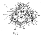
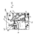
- Figure 1 represents a perspective view of one exemplary embodiment of an apparatus 10 for laminating a patch film onto personalized cards.
- the apparatus 10 generally includes a frame 12 having ends 12a, 12b.
- the frame 12 can support a supply component 42 and a take-up component 44 proximate end 12a.
- the frame 12 may be provided with generally planar surfaces for supporting any components thereon, including the supply component 42 and the take-up component 44.
- the supply component 42 may include a supply spindle assembly 42a for supporting a roll of web material 48 having a plurality of patch films 46 arranged thereon (patch films 46 shown in Figures 2A-2D ).
- the supply spindle assembly 42a delivers the web material 48 and patch films 46 to personalized cards 40 that enter the apparatus 10.
- Guide pins may be employed to facilitate delivery of the web material 48 and patch films 46 to an area where affixing of the patch film 46 onto the personalized card 40 is desired.
- term affix may include the term tack, defined here as a temporary adhesion, such as a temporary adhesion of the patch film to the personalized card. It will also be appreciated that the term affix is non-limiting so long as at least a portion of the patch film can be placed on the personalized document.
- the web material is made up of a supply of patch films that are perforated such that when lamination occurs a portion of the web material corresponding to the patch film to be laminated on the personalized document is removed from where the perforation is located and is laminated on the personalized document.
- the patch film is a coating or overlay on the web material that is capable of being transferred to or laminated on the personalized card.
- the take-up component 44 may include a take-up spindle assembly 44a for receiving the web material 48 after patch films 46 have been delivered to a personalized card 40.
- the take-up spindle receives the web material 48 after a patch film 46 has been delivered to the personalized card 40 and removed from the web 48.
- the frame supports a card path 18 for enabling entry and exit of a personalized card 40 to be laminated. Entry rollers 36a and exit rollers 36b further facilitate the entry and exit of a personalized card 40 for transferring the personalized card 40 downstream.
- the frame 12 may also include a plurality of bolt holes for attaching the apparatus 10 to a card processing system (not shown).
- the apparatus 10 can be powered and controlled, through any means known in the art, and can be operated through a number of motors.
- the frame supports at least one motor 11 for driving the rollers.
- a motor 16 may drive a platen structure 20 and a motor 14 may drive a lamination assembly, of which the platen structure 20 and lamination assembly 30 are further described hereinafter.
- the frame supports a platen structure 20 for affixing a portion of the patch film 46 to a portion of one side of the personalized card 40 when the supply component 42 delivers the patch film 46 to the personalized card 40.
- the platen structure 20 is movable to and from the card path 18, and may be disposed between delivery of the web material 48 and patch film 46 from the supply component 42 to the personalized card 40 and take-up of the web material 48 by the take-up component 44.
- the term platen structure is construed broadly to include any structure having a surface for exerting or receiving pressure on a planar surface, such as the surface of a personalized card.
- portion of the patch film may mean a part that is less than the entire patch film, and that the term portion of one side of the personalized card may mean a part that is less than the entire surface of one side of the personalized card.
- the platen structure 20 includes a head portion 22 having an end surface 20d (best shown in Figures 2A-2B ) for contacting the patch film 46 and pressing a portion of the patch film 46 against the personalized card 40.
- the platen structure 20 may press the patch film 46 against the personalized card when the supply component 42 delivers the web material 48, having the patch film arranged thereon, between the platen structure 20 and the personalized card 40.
- the platen structure 20 can move towards and away from the card path 18. Movement of the platen structure 20 will be further described below.
- the head portion 22 of the platen structure 20 can include a space or hole 20a therein for supporting a heating element 21 (best shown in Figure 3 ) for heating the end surface 20d.
- a portion of the patch film 46 can be affixed to a portion of the personalized card 40 when pressed against the personalized card 40.
- the portion of the patch film 46 that affixes to the personalized card 40 can be a lead portion (best shown in Figures 2B-2C ).
- the portion of the personalized card 40 that the lead portion of the patch films affixes to can be a lead portion of the personalized card 40.
- the lead portion of the personalized card 40 may be about a 0.25 inch (about 6.35 mm) leading edge of the personalized card 40.
- the heating element 21 can heat the lead portion of the patch film 46 to about 300°F (about 148.89°C) for affixing the portion of the patch film to the lead portion of the personalized card.
- the platen structure 20 may include a space or hole 20b therein for supporting a thermocouple element 23.
- the thermocouple element can measure the temperature of the platen structure 20, particularly the end surface 20d, and can facilitate monitoring of the same.
- the head portion 22 may include a tapered portion 20c along side surfaces thereof.
- the tapered portion 20c tapers toward the end surface 20d so that the end surface 20d has a reduced surface area (best shown in Figures 2A-2B ).
- the force of the platen structure 20 may be concentrated in a reduced or narrowed surface area to better facilitate affixing the portion of the patch film 46 to the personalized card 40.
- the reduced surface area of the end surface 20d can also allow a strip pin (described below) to be disposed closer to the platen affixing process. This configuration may help to achieve decreased patch film spacing on a roll of web material, so as to increase the number of patch films that may be supported on a roll of web material and lower costs for patch films.
- the end surface 20d may also be a substantially planar surface. It will be appreciated that the end surface 20d can be construed broadly to include any suitable surface for exerting or receiving pressure on a planar surface, such as the surface of a personalized card.
- the end surface may also be configured as a slightly radiused surface. As best shown in Figures 2A-2B , the end surface 20d may be radiused from a leading/downstream end to a trailing/upstream end, where the leading end is substantially planar and the trailing end is slightly arcuate or curved. In this manner, the pressure exerted by the end surface 20d on a personalized card during affixing can be distributed in a decreasing fashion from the lead most portion of the card.
- the apparatus 10 may further comprise a strip pin 26 disposed downstream of and adjacent to the platen structure 20.
- the strip pin 26 is proximate the end surface 20d and the tapered portion 20e, such that the strip pin 26 may be disposed directly adjacent to the platen structure 20. In this configuration, removal of the patch film 46 from the web material 48 can be facilitated.
- the platen structure 20 may be moved towards and away from the card path 18 through a platen support 28.
- the platen support 28 imparts movement to the platen structure and may be moved by any suitable means known in the art.
- the platen structure 20 may be moved through electrical power and control.
- the platen structure 20 may be operatively connected with and electrically driven by a motor 16.
- Figures 6A and 6B illustrate a platen support 28 for the platen structure 20, which includes a drive and compression mechanism 50 for moving the platen structure 20 before and during affixing the patch film 46 to the personalized card 40.
- the mechanism 50 can provide both driving and load compression functions, and may provide both functions simultaneously during affixing (see Figure 6B ).
- the mechanism 50 includes a support block 52.
- the support block 52 supports a ball screw 54 that can be inserted through the support block 52.
- a ball screw nut 58 may be used to secure the ball screw 54 with the support block 52.
- a compression spring 56 may be disposed about the ball screw 54. As shown, the compression spring 56 may be longitudinally disposed around a portion of the ball screw 54.
- the ball screw 54 may be turned to advance the platen structure 20 to the card 40. While the platen structure 20 advances the compression spring 56 may compress to a desired pressure.
- An anti-rotate bearing 51 and load thrust bearing 53 may be employed to adjust the compressive load of the compression spring 56.
- the thrust load bearing 53 may be a well known ball bearing.
- the ball screw 54 may include a shoulder, that when loaded, transmits the load to an inner race of the thrust load bearing.
- An outer race of the load thrust bearing 53 can be mounted against a shoulder in a bearing block which transmits the load to the mechanism 50. As the load is applied by rotating the screw 54, a tendency may be for a ball nut to rotate with the ball screw, making it unable to load the spring.
- the anti-rotate bearing 51 may be added, which includes a ball nut mount and a capture screw. Clearance may be provided so the anti-rotate bearing 51 and ball nut mount are able to move in an axis parallel to the ball screw 54, but may be captured on the sides preventing the ball nut, ball nut mount and anti-rotate bearing from rotating about the same axis. In such a configuration, compression of the load spring can be enabled, without loss by a tendency of reverse rotation of the ball nut.
- a capture screw may also be employed hold the anti-rotation elements, so as to prevent separation of the elements when reversing the load.
- mechanism 50 is merely exemplary, and that other configurations for advancing the platen structure 20 and applying a compressive load may be equally or more suitable.
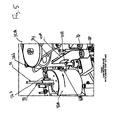
- Figure 3 represents a partial perspective view showing one embodiment of a platen structure 20 having a gimbaled configuration. That is, the platen structure 20 can be pivotable with respect to the platen support 28.
- the pivot support 28 includes a pivot point 25, whereby a shaft may be inserted through the body of the platen support 28 and the head portion 22 of the platen structure 20.
- the pivot point 25 enables the platen structure 20 to be pivotably supported on the platen support 28.
- the platen structure 20 may be pivoted along a horizontal axis (direction of arrow illustrated) such that the platen structure 20 may better facilitate pressing the patch film 46 against the personalized card 40.
- a gimbaled configuration will be construed broadly to include a configuration for freely inclining or declining the platen structure 20 in a pivoting direction.
- the pivot configuration for the platen structure is exemplary only.
- the platen structure may be pivoted by any suitable means known in the art.
- the platen support 28 and pivot point 25 should be construed broadly as simply requiring any means for pivoting the platen structure 20 against the patch film 46 and personalized card 40.
- the frame 12 may further support a backing plate 24.
- the backing plate may be a gusset or any suitable reinforcement structure that is disposed opposite the platen structure 20. That is, the backing plate 24 may be disposed on the other side of the card path 18.
- the backing plate can provide a support surface when the platen structure presses the portion of the patch film 46 onto the personalized card 40.
- the frame 12 supports intermediate rollers 38.
- the intermediate rollers 38 may be idling rollers that help keep the patch film and personalized card 40 together during transfer to the lamination assembly 30 (described hereinafter). That is, after the portion of the patch film 46 is affixed to the portion of the personalized card 40, a remaining portion of the patch film 46 that is to be laminated by the lamination assembly 30 may need to be held together until lamination has been completed.
- the intermediate rollers 38 can achieve this effect by helping to keep the patch film 46 and personalized card 40 together prior to lamination.
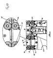
- FIGs 4A-4D illustrate an exemplary embodiment for a lamination assembly 30.
- the lamination assembly includes a lamination shoe 32 supported by the frame 12 and a backing roller 34 for the lamination shoe 32 to press against when a personalized card 40 is delivered between the lamination shoe 32 and the backing roller 34.
- the lamination shoe 32 may be supported on the frame 12 by a support 35 and can be rotatable with respect to the support 35 and frame 12.
- the lamination shoe 32 may be spring loaded so as to be biased in a lamination ready position (as shown in Figure 4A ). In operation, the lamination shoe 32 can be driven into contact with the personalized card 40 and press the card 40 against the backing roller 34.
- the backing roller 34 rotates to drive the card 40 and imparts rotation on the lamination shoe 32, so as to laminate an affixed patch film to an entire side of the personalized card 40. That is, the backing roller 34 can further drive and rotate the lamination shoe 32, when the lamination shoe contacts and presses the patch film on the personalized card 40 and against the backing roller 34.
- the lamination assembly 30 drives and rotates the lamination shoe 32 to press the patch film 46 onto the personalized card 40.
- Lamination contact and pressure may be made when a ball screw turns to advance the lamination shoe 32 to the personalized card 40 against the backing roller (best shown in Figures 7A-7B discussed below).
- a spring may be compressed to a desired pressure.
- the backing roller 34 may then rotate to drive the card 40 and rotate the lamination shoe 32 until the entire patch film 46 is laminated to the card 40. In this configuration, lamination of the entire patch film 46 to an entire side of the personalized card 40 can be finalized.
- the lamination assembly 30 includes heat transfer capability to facilitate laminating the entire patch film 46 onto the personalized card 40.
- the lamination shoe 32 may be heated.
- the lamination shoe 32 may include a space or hole 32a for supporting a heating element 31 for heating lamination shoe 32.
- the heating element 31 can heat the lamination shoe 32 to about 410°F (210°C).
- the lamination assembly may further include an IR thermal detector 70 that is configured to monitor the surface temperature of the lamination shoe (shown in Figure 4C ).
- an IR thermal detector 70 that is configured to monitor the surface temperature of the lamination shoe (shown in Figure 4C ).
- One advantage of using an IR thermal detector 70 as opposed to a thermocouple to monitor temperature of the lamination assembly is that the IR thermal detector 70 requires less moving wires within the assembly.
- the lamination shoe 32 may include a space or hole 32b therein for supporting a thermocouple element 33.
- the thermocouple element can measure the temperature of the lamination shoe 32, and can facilitate monitoring of the same.
- Figure 4A represents the lamination shoe 32 in a state at the start of lamination.
- Figure 4B represents the lamination shoe 32 in a state at the end of lamination.
- the lamination shoe 32 includes an arcuate surface having a chord length that is longer than a length of a personalized card 40. In this manner, the lamination shoe 32 can assure contact against the entire card 40 when pressing the patch film 46 against it to laminate the patch film 46 on the personalized card 40.
- the lamination shoe 32 includes generally a half circle that is biased back to the ready position each time a card is to be laminated. In this manner, the lamination shoe is in the correct position to align with, for instance a smart card chip.
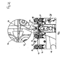
- Figures 2A through 2D illustrate the apparatus 10 in operation. Like reference numerals represent like features already described.
- Figure 2A represents the platen structure 20 and the personalized card 40 in a state before affixing of a patch film 46.
- Figure 2B represents the personalized card 40 in a state during affixing of the patch film 46.
- Figure 2C represents the personalized card 40 after affixing of the patch film 46 and during stripping of the patch film 46 from the web material 48.
- Figure 2D represents personalized card 40 after stripping of the patch film 46 from web material 48 and being secured and transferred by the intermediate rollers 38.
- FIG 4D illustrates another embodiment for a lamination assembly 30A.
- Personalized card 40 is secured and transferred by the intermediate rollers 38 and a movable roller 72.
- the movable roller 72 may be independently driven to move in the direction of arrow 74.
- the adjustment of the movable roller 72 allows the lamination assembly to laminate the personalized card 40 with patch films 46 (best shown in Figures 2A and 2B ) of varying thicknesses.
- Adjustment of the movable roller 72 can also prevent wrinkles from being formed by the lamination of the patch film 46 on the personalized card 40 by removing the surface restriction caused by the contact of the movable roller 72 on the surface of the patch film 46, thereby facilitating the patch film 46 to move and flex freely during the lamination.
- FIG. 5 illustrates another embodiment for a lamination assembly 30A.
- the lamination assembly may include a lamination shoe 32A.
- Like reference numerals represent like features already described.
- the lamination shoe 32A includes a cutout portion 32B that may correspond with a laminate sensitive area 40B on a personalized card 40.
- the corresponding laminate sensitive area may be a smart card chip disposed on a personalized card 40A.
- the cutout portion 32A may enable such personalized cards 40A having a laminate sensitive area 40B to be transferred through without compromising the laminate sensitive area 40B, such as a smart card chip.
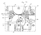
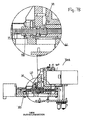
- Figures 7A and 7B illustrate the lamination assembly 30A of Figure 5 , which includes a mechanism 60 for moving the lamination shoe 32A before and during lamination of the entire patch film 46 to the personalized card 40.
- the mechanism 60 may provide both driving and load compression functions, and may provide both functions simultaneously during lamination.
- the mechanism 60 includes a support block 62.
- the support block 62 supports a ball screw 64 that can be inserted through the support block 62.
- a ball screw nut 68 may be used to secure the ball screw 64 with the support block 62.
- a compression spring 66 may be disposed about the ball screw 64. As shown, the spring 66 may be longitudinally disposed around a portion of the ball screw 64.
- the ball screw 64 turns to advance the lamination shoe 32A to the personalized card 40 against the backing roller 34.
- the compression spring 66 may be compressed to a desired pressure.
- the backing roller 34 may then rotate to drive the card 40 and rotate the lamination shoe 32A until the entire patch film 46 is laminated to the card 40. In this configuration, lamination of the entire patch film 46 to an entire side of the personalized card 40 can be finalized.
- an anti-rotate bearing 61 and load thrust bearing 63 may also be employed to adjust the compressive load of the compression spring 66.
- mechanism 60 is merely exemplary, and that other configurations for advancing the platen structure 20 and applying a compressive load may be equally or more suitable.
- a method for laminating personalized cards includes delivering a patch film disposed on a web material to a personalized card from a source of supply.
- the patch film is contacted by a platen structure at a portion of the patch film.
- the platen structure presses the portion of the patch film against the personalized card.
- the platen structure may be heated such that, when the platen structure presses the portion of the patch film against the personalized card, the portion of the patch film may affix to a portion of one side of the personalized card.
- the patch film has been partially affixed to the personalized card, the remaining portion of the patch film is removed from the web by a stripping pin.
- the entire patch film is then laminated to the entire side of the personalized card through the lamination assembly.
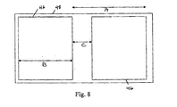
- Figure 8 shows an exemplary configuration of the patch film on a web material.
- a patch film supply comprises a web material having a plurality of patch films disposed thereon.
- the patch film 46 as described may be any material capable of being laminated onto a personalized card, and having detail printed thereon prior to lamination onto a personalized card.
- the patch film may also be constructed to include a smart card chip thereon.
- the web can be arranged as a roll of web material.
- the patch films on the roll of web material are configured for laminating each of the patch films to a personalized card in an apparatus for laminating personalized cards.
- the patch films are arranged on the web material so as to be substantially close together.
- the lamination shoe includes an arcuate surface having a chord length and height that is larger than the personalized card.
- the arcuate surface of the lamination shoe has a chord length and height that is smaller than the personalized card, but larger than the length and height of a patch film to be laminated.
- a lamination shoe is sized to laminate a portion of the personalized card that is smaller than the entire surface of the personalized card (i.e. laminating over the photograph on a driver's license).
- the patch films 46 are configured on the web material 48 for delivery to a personalized card in an apparatus such as apparatus 10, where a mechanism for stripping each patch film 46 from the web material 48 is directly adjacent to an area where an affixing mechanism affixes a portion of the patch film to the personalized card.
- Figure 8 shows one embodiment of the patch films 46 arranged on the web material 48.
- the patch films 46 can be spaced apart at a distance of about 4.0 inches (about 101.6 mm) from a leading edge of one patch film to a leading edge of the next patch film 46 (shown as A).
- the length of one patch film 46 can be about 3.31 inches (about 84.074 mm) in length (shown as B), where the length of the patch film 46 can be shorter on each end lengthwise by about 0.030 inches (about .762 mm) for a traditional 3.375 inch (about 85.725 mm) personalized card.
- patch film 46 spacing may be decreased on the web material 48 to as low as 0.69 inches (about 17.526 mm) or lower (shown as C).
- the number of patches per roll of web material 48 may be increased, which can lower patch film costs.
- the patch film may have a height of about 1.42 inches (about 36.068 mm) and a length of about 1.09 inches (about 27.686 mm).
- the card path 18 drives the personalized card 40 in one direction toward and through the apparatus 10.
- the spacing from a trailing edge of one patch film to a leading edge of the next patch film is limited only by the width of the planar end surface of the platen structure.
- the apparatus 10 may be configured so that the supply component 42 and or the take-up component 44 guides the web material 48 forward and backward through the apparatus 10, so as to position the patch film 46 with respect to the platen structure to thereby affix a portion of a patch film 46 onto the personalized card 40.
- the supply component 42 and or the take-up component 44 guides the web material 48 forward and backward through the apparatus 10, so as to position the patch film 46 with respect to the platen structure to thereby affix a portion of a patch film 46 onto the personalized card 40.
- the present disclosure may provide advantages such that the platen structure may allow faster strip speed, which can achieve greater throughput.
- the narrow platen structure may allow a strip pin to be closer to the area of affixation by the platen structure, so as to be directly adjacent to the platen structure. In this manner, patch spacing on a web material may be decreased and the number of patch films per roll may be increased, so as to achieve a decrease in patch price.
- the present disclosure can also provide a lamination shoe that is biased into a lamination ready position. In this manner, delay in card processing can be reduced, because the lamination shoe may already be in position to laminate the next personalized card right after processing a preceding card.
- a cutout portion may be provided in the lamination shoe, which can achieve better throughput for cards, including cards having laminate sensitive areas, for example cards with smart card chips.
- the heater element within the platen structure may also save on costs.
Claims (12)
- Appareil (10) pour plastifier un document personnalisé, l'appareil comportant :un composant d'alimentation (42) contenant un matériau en bande (48) qui est configuré pour délivrer un film de patchs (46) au document personnalisé (40) ; etun composant de retrait (44) configuré pour recevoir le matériau en bande après que le film de patchs est délivré au document personnalisé ;caractérisé en ce que l'appareil comporte en outre un plateau (20) comportant une partie avant (22) possédant une surface terminale (20d), configurée pour fixer une partie du film de patchs qui est plus petite que le film de patchs entier délivré par le composant d'alimentation à une partie de côté du document personnalisé qui est plus petite que le côté entier du document personnalisé ; etun assemblage de plastification (30) configuré pour plastifier une partie restante du film de patchs sur le document personnalisé après y avoir fixé partiellement le film de patchs grâce à la structure de plateau.
- Appareil selon la revendication 1, dans lequel le plateau (20) comporte un élément chauffant (21) pour chauffer la surface terminale de la partie avant afin de fixer la partie du film de patchs à la partie d'un côté du document personnalisé.
- Appareil selon la revendication 1, dans lequel la surface terminale (20d) comporte une surface terminale sensiblement plane possédant une extrémité avant et une extrémité arrière et la surface terminale plane tourne légèrement vers l'extrémité arrière.
- Appareil selon la revendication 1, dans lequel la partie avant comporte en outre une pluralité de surfaces latérales qui diminuent vers la surface terminale.
- Appareil selon la revendication 1, dans lequel l'appareil comporte une clavette (26) configurée pour faciliter l'enlèvement du film de patchs du matériau en bande, la clavette étant disposée en aval de et adjacente au plateau proche de la surface terminale.
- Appareil selon la revendication 1, dans lequel le plateau est configuré pour fixer une partie du film de patchs délivré par le composant d'alimentation à une partie d'un côté du document personnalisé, le plateau étant configuré pour se déplacer vers et depuis un trajet de carte (18) qui permet l'entrée et la sortie du document personnalisé à plastifier.
- Appareil selon la revendication 1, dans lequel l'assemblage de plastification (30) comporte :un cylindre de plastification chauffé (32) ;un contre-rouleau (34) qui vient contre le cylindre de plastification et est configuré pour plastifier la partie entière du film de patchs sur le côté entier du document personnalisé lorsqu'un document personnalisé est délivré entre le cylindre de plastification et le contre-rouleau.
- Procédé pour plastifier des documents personnalisés, le procédé comportant :la délivrance d'un film de patchs (46) disposé sur un matériau en bande (48) depuis un composant d'alimentation (42) sur un document personnalisé (40) ;la mise en contact d'un plateau (20) sur une partie d'un côté du film de patchs qui est inférieure au film de patchs entier ;la fixation de la partie du film de patchs qui est plus petite que le film de patchs entier sur une partie d'un côté du document personnalisé qui est plus petite que le côté entier du document personnalisé en utilisant le plateau ;la plastification d'une partie restante du film de patchs sur le document personnalisé grâce à l'assemblage de plastification.
- Procédé selon la revendication 8, comportant en outre le chauffage d'une surface terminale du plateau de sorte que, lorsque le plateau presse la partie du film de patchs contre le document personnalisé, le film de patchs est fixé à la partie d'un côté du document personnalisé.
- Procédé selon la revendication 8, comportant en outre l'enlèvement d'une partie restante du film de patchs de la bande par une clavette (26).
- Procédé selon la revendication 8, comportant en outre l'inclinaison d'un cylindre de plastification vers une position de plastification en stand-by pour plastifier un film de patchs suivant après plastification d'un film de patchs sur le côté entier du document personnalisé.
- Procédé selon la revendication 8, comportant en outre la plastification du film de patchs entier sur le côté entier du document personnalisé sauf une surface sensible à la plastification du document personnalisé.
Applications Claiming Priority (4)
| Application Number | Priority Date | Filing Date | Title |
|---|---|---|---|
| US73527305P | 2005-11-10 | 2005-11-10 | |
| US74874005P | 2005-12-09 | 2005-12-09 | |
| US11/557,615 US7638012B2 (en) | 2005-11-10 | 2006-11-08 | Lamination of patch films on personalized cards through heat transfer |
| PCT/US2006/060735 WO2007059412A2 (fr) | 2005-11-10 | 2006-11-09 | Application de patchs de plastification sur des cartes personnalisees par transfert thermique |
Publications (3)
| Publication Number | Publication Date |
|---|---|
| EP1948414A2 EP1948414A2 (fr) | 2008-07-30 |
| EP1948414A4 EP1948414A4 (fr) | 2010-12-01 |
| EP1948414B1 true EP1948414B1 (fr) | 2014-08-13 |
Family
ID=38002553
Family Applications (1)
| Application Number | Title | Priority Date | Filing Date |
|---|---|---|---|
| EP06839800.7A Active EP1948414B1 (fr) | 2005-11-10 | 2006-11-09 | Application de patchs de plastification sur des cartes personnalisees par transfert thermique |
Country Status (8)
| Country | Link |
|---|---|
| US (1) | US7638012B2 (fr) |
| EP (1) | EP1948414B1 (fr) |
| JP (1) | JP4896151B2 (fr) |
| KR (1) | KR20080075084A (fr) |
| CN (1) | CN101304862B (fr) |
| CA (1) | CA2621288A1 (fr) |
| HK (1) | HK1122536A1 (fr) |
| WO (1) | WO2007059412A2 (fr) |
Families Citing this family (5)
| Publication number | Priority date | Publication date | Assignee | Title |
|---|---|---|---|---|
| US9676179B2 (en) * | 2005-04-20 | 2017-06-13 | Zih Corp. | Apparatus for reducing flash for thermal transfer printers |
| MX2007013199A (es) | 2005-04-20 | 2008-11-04 | Zih Corp | Procedimiento y sistema para transferencia de imagen de dos lados de un solo paso. |
| JP3156423U (ja) * | 2006-11-16 | 2010-01-07 | データカード・コーポレイシヨン | 小型パッチラミネート |
| DE102010053655A1 (de) * | 2010-12-07 | 2012-06-14 | Heidelberger Druckmaschinen Ag | Spotkaschierung mit Folie |
| CN109160358A (zh) * | 2018-07-16 | 2019-01-08 | 安徽吉乃尔电器科技有限公司 | 一种包装带粘合补片用贴合装置 |
Family Cites Families (38)
| Publication number | Priority date | Publication date | Assignee | Title |
|---|---|---|---|---|
| US3346440A (en) * | 1964-08-14 | 1967-10-10 | Kimball Systems Ltd | Patching means for restoring punched card field |
| US4133926A (en) * | 1977-07-05 | 1979-01-09 | American Hoechst Corporation | Laminated identification card having special interlaminar adhesive |
| US4380484A (en) * | 1981-02-20 | 1983-04-19 | William C. Heller, Jr. | Inductively heated tooling and method for working plastic members |
| GB2095171A (en) * | 1981-02-27 | 1982-09-29 | Ushio Electric Inc | Apparatus for heat-laminating a sheet |
| US4402597A (en) * | 1981-08-06 | 1983-09-06 | Energy Conversion Devices, Inc. | Filmstrip for preventing fogging of intermediate film in microfiche recording systems |
| IT1210033B (it) * | 1982-02-10 | 1989-09-06 | Bc Chem Srl | Macchina per applicare una porzione di film fotosensibile su almeno unafaccia di una lastra piana avente una estensione superficiale maggiore di detta porzione |
| US4818852A (en) * | 1986-01-24 | 1989-04-04 | Drexler Technology Corporation | Method for forming data cards with registered images |
| US4825054A (en) * | 1988-02-16 | 1989-04-25 | Datacard Corporation | Method and apparatus for parallel integrated circuit card initialization and embossing |
| NL8800973A (nl) * | 1988-04-14 | 1989-11-01 | Cardee Netherlands B V | Werkwijze voor het vervaardigen van prentbriefkaarten alsmede inrichting voor het uitvoeren van de werkwijze. |
| US5266781A (en) * | 1991-08-15 | 1993-11-30 | Datacard Corporation | Modular card processing system |
| JP2720244B2 (ja) * | 1992-06-11 | 1998-03-04 | 富士写真フイルム株式会社 | 積層方法 |
| FR2716411B1 (fr) * | 1994-02-24 | 1996-04-26 | Gemplus Card Int | Machine imprimante en couleurs. |
| US5788806A (en) * | 1994-05-20 | 1998-08-04 | Xyron, Inc. | Laminating and adhesive transfer apparatus |
| US5489356A (en) * | 1994-06-13 | 1996-02-06 | Transilwrap Company, Inc. | Method of manufacturing a secure identification card |
| US5821976A (en) * | 1994-09-28 | 1998-10-13 | Toppan Printing Co., Ltd. | Image-forming apparatus |
| US5781316A (en) * | 1995-02-28 | 1998-07-14 | Transfer Print Foils, Inc. | Semi-transparent reflective hologram and method of producing same |
| US5673076A (en) * | 1995-03-13 | 1997-09-30 | Atlantek Inc. | Card printing and laminating apparatus |
| JP3061354B2 (ja) * | 1995-05-23 | 2000-07-10 | ソマール株式会社 | フィルム張付方法及び装置 |
| JP3366791B2 (ja) * | 1995-11-09 | 2003-01-14 | ニスカ株式会社 | 情報記録装置 |
| US6030474A (en) * | 1995-11-30 | 2000-02-29 | Nisca Corporation | Information card coating method |
| US6001893A (en) * | 1996-05-17 | 1999-12-14 | Datacard Corporation | Curable topcoat composition and methods for use |
| WO1997043319A1 (fr) * | 1996-05-17 | 1997-11-20 | Datacard Corporation | Composition de couche de finition polymerisable et procedes d'utilisation |
| US6350342B1 (en) * | 1996-09-09 | 2002-02-26 | Tamarack Products Inc. | Method of making integrated label products |
| US5776287A (en) * | 1996-10-18 | 1998-07-07 | Saxon Incorporated | Coupon manufacturing machine |
| JP3744117B2 (ja) * | 1997-04-28 | 2006-02-08 | 凸版印刷株式会社 | 転写方式によるオーバーコーティング装置 |
| US6095220A (en) * | 1997-06-23 | 2000-08-01 | Nisca Corporation | Overcoat fixing device |
| US6263796B1 (en) | 1997-12-23 | 2001-07-24 | Datacard Corporation | Closed loop control for an image transfer section of a printer |
| ATE219426T1 (de) * | 1998-03-10 | 2002-07-15 | Rue De Int Ltd | Verfahren zur herstellung eines sicherheitsgegenstands |
| GB2338678B (en) | 1998-06-25 | 2000-05-17 | Rue De Int Ltd | Improvements in security documents and substrates therefor |
| US6315023B1 (en) * | 1999-04-30 | 2001-11-13 | Saxon, Inc. | Card manufacturing machine assembly |
| JP2001219681A (ja) | 2000-02-10 | 2001-08-14 | Dainippon Printing Co Ltd | 装飾体 |
| US6459880B1 (en) * | 2000-11-28 | 2002-10-01 | Xerox Corporation | Document creating system including a film for bonding the document together |
| FR2826135B1 (fr) * | 2001-06-15 | 2003-08-08 | Thales Sa | Procede de realisation en serie de documents securises et machine de mise en oeuvre |
| EP1456810B1 (fr) * | 2001-12-18 | 2011-05-11 | L-1 Secure Credentialing, Inc. | Elements de securite a images multiples pour documents d'identification, et procedes de realisation |
| US6902107B2 (en) * | 2002-01-28 | 2005-06-07 | Datacard Corporation | Card personalization system and method |
| US20050087604A1 (en) * | 2003-10-27 | 2005-04-28 | Nguyen Cam V. | Licensing and identification devices having coded marks and methods of making and authenticating such licensing and identification devices |
| MX2007013199A (es) * | 2005-04-20 | 2008-11-04 | Zih Corp | Procedimiento y sistema para transferencia de imagen de dos lados de un solo paso. |
| JP4730177B2 (ja) * | 2006-04-06 | 2011-07-20 | 日本ビクター株式会社 | ラミネート装置 |
-
2006
- 2006-11-08 US US11/557,615 patent/US7638012B2/en active Active
- 2006-11-09 CN CN2006800420961A patent/CN101304862B/zh active Active
- 2006-11-09 EP EP06839800.7A patent/EP1948414B1/fr active Active
- 2006-11-09 JP JP2008540346A patent/JP4896151B2/ja not_active Expired - Fee Related
- 2006-11-09 CA CA002621288A patent/CA2621288A1/fr not_active Abandoned
- 2006-11-09 WO PCT/US2006/060735 patent/WO2007059412A2/fr active Application Filing
- 2006-11-09 KR KR1020087006860A patent/KR20080075084A/ko not_active Application Discontinuation
-
2009
- 2009-04-02 HK HK09103136.0A patent/HK1122536A1/xx not_active IP Right Cessation
Also Published As
| Publication number | Publication date |
|---|---|
| EP1948414A4 (fr) | 2010-12-01 |
| HK1122536A1 (en) | 2009-05-22 |
| WO2007059412A2 (fr) | 2007-05-24 |
| US20070102104A1 (en) | 2007-05-10 |
| US7638012B2 (en) | 2009-12-29 |
| CN101304862B (zh) | 2012-10-03 |
| EP1948414A2 (fr) | 2008-07-30 |
| WO2007059412A3 (fr) | 2007-09-20 |
| JP4896151B2 (ja) | 2012-03-14 |
| JP2009515736A (ja) | 2009-04-16 |
| KR20080075084A (ko) | 2008-08-14 |
| CN101304862A (zh) | 2008-11-12 |
| CA2621288A1 (fr) | 2007-05-24 |
Similar Documents
| Publication | Publication Date | Title |
|---|---|---|
| EP2999599B1 (fr) | Mécanisme de suppression de déformation en arc de carte | |
| EP1948414B1 (fr) | Application de patchs de plastification sur des cartes personnalisees par transfert thermique | |
| US7767050B2 (en) | Laminating roller assembly, credential substrate laminator and method of laminating a credential substrate | |
| EP2521652B1 (fr) | Appareil à laminer à tête de laminage comprenant plusieurs éléments chauffants activables sélectivement et méthode d'utilisation associée | |
| EP1957257B1 (fr) | Dispositif et procédé pour supprimer la déformation en arc de documents personnalisés | |
| US6484780B2 (en) | Card laminator and method of card lamination | |
| US20200282716A1 (en) | Card substrate laminating device | |
| EP3172050B1 (fr) | Réduction de gauchissement de substrat de carte | |
| CN109195774B (zh) | 层压装置 | |
| US6561248B2 (en) | Lamination system | |
| JP5334256B2 (ja) | 記録カード処理装置及び記録カード作成方法 | |
| JP5485609B2 (ja) | 記録カード処理装置 | |
| EP3216604B1 (fr) | Dispositif et procédé de laminage de timbre | |
| JP3772050B2 (ja) | 冊子用記録装置および冊子用記録方法 | |
| JP3894304B2 (ja) | ラミネータ装置 | |
| JPH11219522A (ja) | 磁気ストライプテープ貼付機 | |
| JP2006277319A (ja) | Icカードの製造方法及びicカードの製造装置 |
Legal Events
| Date | Code | Title | Description |
|---|---|---|---|
| PUAI | Public reference made under article 153(3) epc to a published international application that has entered the european phase |
Free format text: ORIGINAL CODE: 0009012 |
|
| 17P | Request for examination filed |
Effective date: 20080521 |
|
| AK | Designated contracting states |
Kind code of ref document: A2 Designated state(s): AT BE BG CH CY CZ DE DK EE ES FI FR GB GR HU IE IS IT LI LT LU LV MC NL PL PT RO SE SI SK TR |
|
| A4 | Supplementary search report drawn up and despatched |
Effective date: 20101103 |
|
| 17Q | First examination report despatched |
Effective date: 20110720 |
|
| DAX | Request for extension of the european patent (deleted) | ||
| GRAP | Despatch of communication of intention to grant a patent |
Free format text: ORIGINAL CODE: EPIDOSNIGR1 |
|
| INTG | Intention to grant announced |
Effective date: 20140227 |
|
| GRAS | Grant fee paid |
Free format text: ORIGINAL CODE: EPIDOSNIGR3 |
|
| GRAA | (expected) grant |
Free format text: ORIGINAL CODE: 0009210 |
|
| AK | Designated contracting states |
Kind code of ref document: B1 Designated state(s): AT BE BG CH CY CZ DE DK EE ES FI FR GB GR HU IE IS IT LI LT LU LV MC NL PL PT RO SE SI SK TR |
|
| REG | Reference to a national code |
Ref country code: GB Ref legal event code: FG4D |
|
| REG | Reference to a national code |
Ref country code: AT Ref legal event code: REF Ref document number: 681926 Country of ref document: AT Kind code of ref document: T Effective date: 20140815 Ref country code: CH Ref legal event code: EP |
|
| REG | Reference to a national code |
Ref country code: IE Ref legal event code: FG4D |
|
| REG | Reference to a national code |
Ref country code: DE Ref legal event code: R096 Ref document number: 602006042723 Country of ref document: DE Effective date: 20140925 |
|
| REG | Reference to a national code |
Ref country code: NL Ref legal event code: T3 |
|
| REG | Reference to a national code |
Ref country code: AT Ref legal event code: MK05 Ref document number: 681926 Country of ref document: AT Kind code of ref document: T Effective date: 20140813 |
|
| REG | Reference to a national code |
Ref country code: LT Ref legal event code: MG4D |
|
| PG25 | Lapsed in a contracting state [announced via postgrant information from national office to epo] |
Ref country code: LT Free format text: LAPSE BECAUSE OF FAILURE TO SUBMIT A TRANSLATION OF THE DESCRIPTION OR TO PAY THE FEE WITHIN THE PRESCRIBED TIME-LIMIT Effective date: 20140813 Ref country code: PT Free format text: LAPSE BECAUSE OF FAILURE TO SUBMIT A TRANSLATION OF THE DESCRIPTION OR TO PAY THE FEE WITHIN THE PRESCRIBED TIME-LIMIT Effective date: 20141215 Ref country code: ES Free format text: LAPSE BECAUSE OF FAILURE TO SUBMIT A TRANSLATION OF THE DESCRIPTION OR TO PAY THE FEE WITHIN THE PRESCRIBED TIME-LIMIT Effective date: 20140813 Ref country code: FI Free format text: LAPSE BECAUSE OF FAILURE TO SUBMIT A TRANSLATION OF THE DESCRIPTION OR TO PAY THE FEE WITHIN THE PRESCRIBED TIME-LIMIT Effective date: 20140813 Ref country code: SE Free format text: LAPSE BECAUSE OF FAILURE TO SUBMIT A TRANSLATION OF THE DESCRIPTION OR TO PAY THE FEE WITHIN THE PRESCRIBED TIME-LIMIT Effective date: 20140813 Ref country code: GR Free format text: LAPSE BECAUSE OF FAILURE TO SUBMIT A TRANSLATION OF THE DESCRIPTION OR TO PAY THE FEE WITHIN THE PRESCRIBED TIME-LIMIT Effective date: 20141114 Ref country code: BG Free format text: LAPSE BECAUSE OF FAILURE TO SUBMIT A TRANSLATION OF THE DESCRIPTION OR TO PAY THE FEE WITHIN THE PRESCRIBED TIME-LIMIT Effective date: 20141113 |
|
| PG25 | Lapsed in a contracting state [announced via postgrant information from national office to epo] |
Ref country code: IS Free format text: LAPSE BECAUSE OF FAILURE TO SUBMIT A TRANSLATION OF THE DESCRIPTION OR TO PAY THE FEE WITHIN THE PRESCRIBED TIME-LIMIT Effective date: 20141213 Ref country code: CY Free format text: LAPSE BECAUSE OF FAILURE TO SUBMIT A TRANSLATION OF THE DESCRIPTION OR TO PAY THE FEE WITHIN THE PRESCRIBED TIME-LIMIT Effective date: 20140813 Ref country code: AT Free format text: LAPSE BECAUSE OF FAILURE TO SUBMIT A TRANSLATION OF THE DESCRIPTION OR TO PAY THE FEE WITHIN THE PRESCRIBED TIME-LIMIT Effective date: 20140813 Ref country code: LV Free format text: LAPSE BECAUSE OF FAILURE TO SUBMIT A TRANSLATION OF THE DESCRIPTION OR TO PAY THE FEE WITHIN THE PRESCRIBED TIME-LIMIT Effective date: 20140813 |
|
| PG25 | Lapsed in a contracting state [announced via postgrant information from national office to epo] |
Ref country code: RO Free format text: LAPSE BECAUSE OF FAILURE TO SUBMIT A TRANSLATION OF THE DESCRIPTION OR TO PAY THE FEE WITHIN THE PRESCRIBED TIME-LIMIT Effective date: 20140813 Ref country code: EE Free format text: LAPSE BECAUSE OF FAILURE TO SUBMIT A TRANSLATION OF THE DESCRIPTION OR TO PAY THE FEE WITHIN THE PRESCRIBED TIME-LIMIT Effective date: 20140813 Ref country code: CZ Free format text: LAPSE BECAUSE OF FAILURE TO SUBMIT A TRANSLATION OF THE DESCRIPTION OR TO PAY THE FEE WITHIN THE PRESCRIBED TIME-LIMIT Effective date: 20140813 Ref country code: SK Free format text: LAPSE BECAUSE OF FAILURE TO SUBMIT A TRANSLATION OF THE DESCRIPTION OR TO PAY THE FEE WITHIN THE PRESCRIBED TIME-LIMIT Effective date: 20140813 Ref country code: DK Free format text: LAPSE BECAUSE OF FAILURE TO SUBMIT A TRANSLATION OF THE DESCRIPTION OR TO PAY THE FEE WITHIN THE PRESCRIBED TIME-LIMIT Effective date: 20140813 |
|
| REG | Reference to a national code |
Ref country code: DE Ref legal event code: R097 Ref document number: 602006042723 Country of ref document: DE |
|
| PG25 | Lapsed in a contracting state [announced via postgrant information from national office to epo] |
Ref country code: PL Free format text: LAPSE BECAUSE OF FAILURE TO SUBMIT A TRANSLATION OF THE DESCRIPTION OR TO PAY THE FEE WITHIN THE PRESCRIBED TIME-LIMIT Effective date: 20140813 |
|
| PLBE | No opposition filed within time limit |
Free format text: ORIGINAL CODE: 0009261 |
|
| STAA | Information on the status of an ep patent application or granted ep patent |
Free format text: STATUS: NO OPPOSITION FILED WITHIN TIME LIMIT |
|
| PG25 | Lapsed in a contracting state [announced via postgrant information from national office to epo] |
Ref country code: BE Free format text: LAPSE BECAUSE OF NON-PAYMENT OF DUE FEES Effective date: 20141130 Ref country code: MC Free format text: LAPSE BECAUSE OF FAILURE TO SUBMIT A TRANSLATION OF THE DESCRIPTION OR TO PAY THE FEE WITHIN THE PRESCRIBED TIME-LIMIT Effective date: 20140813 Ref country code: LU Free format text: LAPSE BECAUSE OF FAILURE TO SUBMIT A TRANSLATION OF THE DESCRIPTION OR TO PAY THE FEE WITHIN THE PRESCRIBED TIME-LIMIT Effective date: 20141109 |
|
| REG | Reference to a national code |
Ref country code: CH Ref legal event code: PL |
|
| 26N | No opposition filed |
Effective date: 20150515 |
|
| GBPC | Gb: european patent ceased through non-payment of renewal fee |
Effective date: 20141113 |
|
| PG25 | Lapsed in a contracting state [announced via postgrant information from national office to epo] |
Ref country code: LI Free format text: LAPSE BECAUSE OF NON-PAYMENT OF DUE FEES Effective date: 20141130 Ref country code: CH Free format text: LAPSE BECAUSE OF NON-PAYMENT OF DUE FEES Effective date: 20141130 |
|
| REG | Reference to a national code |
Ref country code: IE Ref legal event code: MM4A |
|
| PG25 | Lapsed in a contracting state [announced via postgrant information from national office to epo] |
Ref country code: IE Free format text: LAPSE BECAUSE OF NON-PAYMENT OF DUE FEES Effective date: 20141109 Ref country code: GB Free format text: LAPSE BECAUSE OF NON-PAYMENT OF DUE FEES Effective date: 20141113 |
|
| REG | Reference to a national code |
Ref country code: FR Ref legal event code: PLFP Year of fee payment: 10 |
|
| PG25 | Lapsed in a contracting state [announced via postgrant information from national office to epo] |
Ref country code: SI Free format text: LAPSE BECAUSE OF FAILURE TO SUBMIT A TRANSLATION OF THE DESCRIPTION OR TO PAY THE FEE WITHIN THE PRESCRIBED TIME-LIMIT Effective date: 20140813 |
|
| PG25 | Lapsed in a contracting state [announced via postgrant information from national office to epo] |
Ref country code: HU Free format text: LAPSE BECAUSE OF FAILURE TO SUBMIT A TRANSLATION OF THE DESCRIPTION OR TO PAY THE FEE WITHIN THE PRESCRIBED TIME-LIMIT; INVALID AB INITIO Effective date: 20061109 Ref country code: TR Free format text: LAPSE BECAUSE OF FAILURE TO SUBMIT A TRANSLATION OF THE DESCRIPTION OR TO PAY THE FEE WITHIN THE PRESCRIBED TIME-LIMIT Effective date: 20140813 Ref country code: BE Free format text: LAPSE BECAUSE OF FAILURE TO SUBMIT A TRANSLATION OF THE DESCRIPTION OR TO PAY THE FEE WITHIN THE PRESCRIBED TIME-LIMIT Effective date: 20140813 |
|
| REG | Reference to a national code |
Ref country code: FR Ref legal event code: PLFP Year of fee payment: 11 |
|
| REG | Reference to a national code |
Ref country code: FR Ref legal event code: PLFP Year of fee payment: 12 |
|
| REG | Reference to a national code |
Ref country code: DE Ref legal event code: R082 Ref document number: 602006042723 Country of ref document: DE Representative=s name: CBDL PATENTANWAELTE GBR, DE |
|
| P01 | Opt-out of the competence of the unified patent court (upc) registered |
Effective date: 20230513 |
|
| PGFP | Annual fee paid to national office [announced via postgrant information from national office to epo] |
Ref country code: NL Payment date: 20231126 Year of fee payment: 18 |
|
| PGFP | Annual fee paid to national office [announced via postgrant information from national office to epo] |
Ref country code: IT Payment date: 20231122 Year of fee payment: 18 Ref country code: FR Payment date: 20231127 Year of fee payment: 18 Ref country code: DE Payment date: 20231129 Year of fee payment: 18 |