EP1947985B2 - Kommunikationsverfahren, besonders für krankenhaus- und pflegebetten - Google Patents
Kommunikationsverfahren, besonders für krankenhaus- und pflegebetten Download PDFInfo
- Publication number
- EP1947985B2 EP1947985B2 EP06805572.2A EP06805572A EP1947985B2 EP 1947985 B2 EP1947985 B2 EP 1947985B2 EP 06805572 A EP06805572 A EP 06805572A EP 1947985 B2 EP1947985 B2 EP 1947985B2
- Authority
- EP
- European Patent Office
- Prior art keywords
- data
- activation
- unit
- operating unit
- bits
- Prior art date
- Legal status (The legal status is an assumption and is not a legal conclusion. Google has not performed a legal analysis and makes no representation as to the accuracy of the status listed.)
- Active
Links
Images


Classifications
-
- H—ELECTRICITY
- H04—ELECTRIC COMMUNICATION TECHNIQUE
- H04L—TRANSMISSION OF DIGITAL INFORMATION, e.g. TELEGRAPHIC COMMUNICATION
- H04L12/00—Data switching networks
- H04L12/28—Data switching networks characterised by path configuration, e.g. LAN [Local Area Networks] or WAN [Wide Area Networks]
- H04L12/40—Bus networks
- H04L12/40006—Architecture of a communication node
-
- H—ELECTRICITY
- H04—ELECTRIC COMMUNICATION TECHNIQUE
- H04L—TRANSMISSION OF DIGITAL INFORMATION, e.g. TELEGRAPHIC COMMUNICATION
- H04L12/00—Data switching networks
- H04L12/28—Data switching networks characterised by path configuration, e.g. LAN [Local Area Networks] or WAN [Wide Area Networks]
- H04L12/40—Bus networks
- H04L12/403—Bus networks with centralised control, e.g. polling
-
- G—PHYSICS
- G16—INFORMATION AND COMMUNICATION TECHNOLOGY [ICT] SPECIALLY ADAPTED FOR SPECIFIC APPLICATION FIELDS
- G16H—HEALTHCARE INFORMATICS, i.e. INFORMATION AND COMMUNICATION TECHNOLOGY [ICT] SPECIALLY ADAPTED FOR THE HANDLING OR PROCESSING OF MEDICAL OR HEALTHCARE DATA
- G16H40/00—ICT specially adapted for the management or administration of healthcare resources or facilities; ICT specially adapted for the management or operation of medical equipment or devices
- G16H40/20—ICT specially adapted for the management or administration of healthcare resources or facilities; ICT specially adapted for the management or operation of medical equipment or devices for the management or administration of healthcare resources or facilities, e.g. managing hospital staff or surgery rooms
-
- H—ELECTRICITY
- H04—ELECTRIC COMMUNICATION TECHNIQUE
- H04L—TRANSMISSION OF DIGITAL INFORMATION, e.g. TELEGRAPHIC COMMUNICATION
- H04L12/00—Data switching networks
- H04L12/28—Data switching networks characterised by path configuration, e.g. LAN [Local Area Networks] or WAN [Wide Area Networks]
- H04L12/40—Bus networks
- H04L2012/4026—Bus for use in automation systems
Definitions
- the invention relates to a method of adjusting adjustable articles of furniture, such as hospital beds and nursing beds as well as patient couches.
- the invention moreover relates to a system for adjusting, comprising an activation unit and a receiver.
- the invention relates to an activation unit and a receiver.
- the disclosure of the invention will be based on a hospital bed, as known e.g. from EP 498 111 B2 to J. Nesbit Evans & Co. Ltd., in which the mattress supporting face may be adjusted to a contour by at least two actuators, and in which the frame, in which the mattress supporting face is mounted, may be raised and lowered as well as titled over a transverse axis (Trendelenburg positions) by two additional actuators.
- a control panel may be incorporated in the guard rail.
- a separate handset as well as a control box may be provided for the staff, mounted at the foot end of the bed where the staff may read all adjustment functions. All these units are connected by individual multi-conductor cables to a central control box (CB), also called a control unit containing a control, a power supply intended for connection to the mains as well as a rechargeable battery pack so that the bed may function temporarily without being connected to the mains.
- CB central control box
- WO 01/47340 to Hill-Rom Services, Inc.
- An example of a simple therapy couch is disclosed in US 5 014 688 to Tri W-G, Inc.
- the control typically comprises a microprocessor and associated software adapted to the individual bed makes and the specific intended uses of the beds.
- a traditional system is characterized in that there is a direct connection from any handset function to the control unit. It is not so that the handset functions can only be arranged in one physical unit; these may very well be distributed on several handsets connected in parallel, but understood in the sense that for each function there is a key (activation unit), and it is connected directly.
- a key may refer to a wire or to a switch between two wires (matrix handsets).
- a maximum of 8 functions (1 common as well as 8 signals) may thus be achieved with a normal 9-conductor cable.
- a maximum of 20 keys (4 x 5 lines) may be achieved using 9 conductors.
- one of the conductors is used for grounding, and, therefore, only a 4 x 4 matrix corresponding to 16 keys can be used.
- Matrix handsets unfortunately have the drawback that several keys cannot be detected with certainty at the same time, as there is no unique decoding as to which keys are activated.
- US 2003/0079289 A1 describes an adjustable bed particularly intended for severely overweight patients.
- the bed may be controlled by serial signals, where adjustments are written in a plurality of RAM circuits, and where the contents are read and executed periodically, controlled by an interrupt.
- This is a relatively complicated control, which requires a good deal of special features, and which is relatively complex to implement and extend with additional functionalities.
- WO2006032283 discloses a system tor adjusting articles of furniture wherein a direct electrical connection is used between activation units and a receiver.
- a further drawback of the foregoing is that they are all based on master - slave communication. This requires that all units in the system are known in advance, since these must have individual addresses in connection with the design of the communication.
- An object of the invention is to provide a solution to the above-mentioned problems.
- the clock signal may have a double function.
- a long pause in the clock signal indicates that a data packet is started.
- This packet is initiated by an identification consisting of e.g. 3 bits, which state the type.
- 32 bits follow, where each bit corresponds to an activation unit which might e.g. be a key on a control unit for a hospital bed, and where the individual bit indicates whether the key is activated.
- the data stream may be made considerably longer or be shared by several data packets, whereby the state of an almost indefinite number of keys may be communicated, and where all may be read uniquely, irrespective of how many have been activated.
- the activation unit might also be a unit connected to the control unit which wishes to communicate its state to another unit.
- the receiver may e.g. be the control unit, which uses the state indication from the activation unit for initiating a specific control, e.g. raising of the head of the bed, as long as the state of an activation unit is activated.
- the receiver might also be other units, e.g. the ACP, to which it is communicated by the method according to the invention that a specific safety setting is activated, and, therefore, a light-emitting diode in the ACP must be turned on to indicate this.
- the receiver might be a Multi Junction Box (MJB), which reads the data signal and is activated - e.g. Under Bed Light on the basis of the state of an activation unit.
- MJB Multi Junction Box
- the system is characterized in that the individual bits are logic 0 when an activation unit is not activated. All activation units, however, have a facility of adding a logic 1, representing that the state of the activation unit is activated.
- the communications bus may be designed so that all can contribute with a logic 1 at every bit position.
- the data stream is not provided with e.g. a check sum or other safety forms, since all units can contribute with active keys.
- a relatively modest processor overhead suffices.
- the very simple communications protocol here makes it possible to make a hardware realization of a handset unit at very low cost.
- the identification part of the data packet is changed from data packet to data packet.
- the purpose of the data packet may be changed.
- the identification part of the data packets is changed in a periodical sequence. This ensures a continuous optimization, and with a period time of e.g. 30 ms all data are transported currently.
- the invention moreover relates to a storage medium comprising instructions which enable a computer to execute the method as described above.
- the invention relates to a system comprising an operating unit and a receiver for adjusting adjustable articles of furniture, such as a hospital bed, wherein activation units on said operating unit are capable of communicating states to the receiver via a communications bus, and wherein the state may be activation/deactivation of the activation unit, said system additionally comprising:
- the invention relates to an actuator system comprising a system according to the invention.
- the invention may be used to advantage, since, typically, there are some operating options.
- the invention relates to an operating unit for communicating states from the activation units on said operating unit to a receiver for adjusting adjustable articles of furniture such as a hospital bed, wherein the state may be activation/deactivation of.the activation unit, and wherein the states are communicated to the receiver via a serial data stream timed by a clock signal, said data stream transmitting data packets which comprise an identification part and a data part, said identification part comprising a plurality of bits which identify the type of data in said data part, said data part comprising a plurality of bits which individually identify the state of an activation unit on said operating unit, said operating unit additionally comprising:
- An activation unit might e.g. be an operating unit with a key, alternatively, an operating unit might comprise a plurality of activation units (keys).
- the invention relates to a receiver for use in a system comprising an operating unit for adjusting adjustable articles of furniture, such as a hospital bed, wherein the operating unit is capable of communicating states from activation units on said operating unit to the receiver via a communications bus, wherein the state may be activation/ deactivation of the activation unit, and wherein the states are communicated to the receiver via a serial data stream timed by a clock signal, said data stream transmitting data packets which comprise an identification part and a data part, said identification part comprising a plurality of bits which identify the type of data in said data part, said data part comprising a plurality of bits which individually identify the state of an activation unit on said operating unit, said receiver additionally comprising:
- the receiver might e.g. be the control unit connected to the operating units in connection with e.g. a hospital bed.
- the receiver might additionally comprise a master unit as described above.
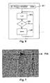
- Figure 1 illustrates a hospital bed 101, and this may be operated via one or more operating units 103.
- One type of operating unit is the handset (HB), which allows the patient in the hospital bed to adjust the various parts of the bed, including the height, the angle of the backrest section and the angle of the legrest section 105.
- ACP Automatic Operating Panel
- the blocking functionality is special, the object being to prevent the patient from adjusting the bed improperly 111.
- the operating units comprise a plurality of keys (activation units), and the function of these depend specifically on how these are coupled to the bed.
- the keys may inter alia have a blocking light 113 indicating that the adjustment of the unit they represent, is blocked.
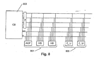
- the operating units 201 communicate 203 with a control unit (CB) 205, and this is shown in figure 2 .
- the control unit (CB) 205 e.g. receives input from the operating units 201, and ensures subsequently that the associated action is performed. This might e.g. be an activation of the raising of a bed head 207.
- a signal is applied to the control unit 205, and the control unit then ensures that precisely the actuator or actuators which adjusts/adjust the backrest section is/are activated.
- a key (activation unit) on an operating unit 201 representing activation of this functionality is activated, and a signal is applied to the control unit 205, following which the control unit transmits a signal to the light part for activating this.
- a further example might be blocking of an adjustment for safety reasons 211.
- a signal is applied to the control unit 205, and the control unit is then effective to block precisely the actuator or actuators which regulates/regulate precisely this adjustment.
- a signal might additionally be sent back to the operating unit for activating a light in the activated key.
- the invention also relates to a communications protocol which may be used in connection with the above-mentioned communication between the activation units and the receivers.
- the protocol will be described below in connection with a control system for hospital beds, but the protocol may also be used generally in connection with systems for the adjustment of furniture, such as e.g. dentist's chairs, beds, armchairs, etc.
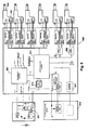
- Fig. 3 illustrates a data signal as it looks in connection with a protocol according to the invention.
- the protocol requires the presence of a master unit which transmits a synchronous clock signal 300 and a data signal 301.
- the clock signal has two functions; it is to indicate that a new data packet 303 is started - and in an embodiment this is done by making a pause 302 of e.g. 5 clock periods - and the clock signal 300 also provides for timing the subsequent data packet 303.
- the data packet 303 is composed of a first identification part 305 identifying which units (handset, ACP, etc.) the subsequent data part concerns, and a subsequent data part 305 which represents the states of the units (which activation units on the handset are activated, which keys are to flash, etc.)
- Figure 4 illustrates an embodiment of the structure of the data packet.
- the data packet consists of 3 identification bits (I 0 , I 1 , I 2 ) 401 and subsequently of 32 data bits (Do, D 1 ...., D 31 ) 403. It is the master unit which determines which data packets are to be transmitted with the data signal, and thus it is the master unit which provides for the filling of identification bits.
- Identification bits identify the type of data in the subsequent data bits. It is shown in the table below how three identification bits might be used: Name I 0 I 1 I 2 HB 0 0 0 ACP 1 0 0 DATA 0 1 0 Service 1 1 0 Reserved 1 0 0 1 Reserved 2 1 0 1 Reserved 3 0 1 1 Reserved 4 1 1 1 1
- identification bits identify that the subsequent data bits concern a handset.
- the master unit fills the identification part, and the value of the subsequent bits depends on which keys are activated on the handset.
- Each of the 32 bits represents a function or a key on a handset, and if the key is activated, the bit value is set high (1). When a key is not activated, the bit value automatically goes to low (0). An embodiment of this is explained in connection with figure 7 .
- key 1 and key 4 are activated, and the remaining keys are not activated. All bits in the data part might represent keys on a handset, but it might also represent a number of handsets with keys. The individual bits just represent an activated key, and then it is the receiver which translates this into a function.
- identification bits identify that the subsequent data bits concern an ACP: ID Data to ACP Data from ACP Bit I 0 I 1 I 2 A 0 A 1 .... A 15 A 16 A 17 .... A 31 Value 1 0 0
- ACP In addition to data from the ACP which identify which keys are activated corresponding to the handsets, there are also data to the ACP. This might e.g. be an indication that a key on the ACP is to flash, since a blocking is activated.
- identification bits identify that the subsequent data bits concern data: ID Data Bit I 0 I 1 I 2 D 0 D 1 .... D 15 D 16 D 17 .... D 31 Value 0 1 0
- This type of data packet is an open part and is used for communication between units.
- the 32 bits may be used for all forms of data between e.g. a control unit and other units.
- identification bits identify that the subsequent data bits concern service data: ID Type R/W Data Bit I 0 I 1 I 2 S 0 S 1 S 2 S 3 S 4 S 5 .... S 31 Value 1 1 0
- Service data are used for service, and the first 3 data bits (So, S 1 , S 2 ) identify which unit the service data concern.
- Data bit S 3 identifies whether reading or writing to the unit is to be performed, and, finally, bits S 4 - S 31 indicate which information is to be read or written.
- FIG. 5 illustrates an example of this.
- identification bits are initially 501 set to indicate that data from a handset (HB) are involved. Then 503, it is data to/from an ACP. Then 505 it is an open data packet, and the process proceeds in this manner through the various data types.
- the process recommences 507, and thereby identification bits are changed in a periodic sequence. The order depends on the individual system and is set up in the master unit.
- Figure 6 shows an example of how a unit, e.g. in the form of an activation unit or a receiver, uses the data signal.
- the unit reads identification bits in the data signal, inter alia by means of the clock signal.
- it is checked whether identification bits concern the unit, and if this is not the case (N), no further steps are taken, and just the process of reading identification bits in the data signal continues. If it turns out in 604 that identification bits concern the unit (Y), then predefined bits are read into the data part, or the value of a bit is set to 1. If e.g. the unit is a handset, and a key (activation unit) is activated on the handset, the data packet concerning data from the handset is awaited.
- the control unit might subsequently read the contents of the data packet and initiate a function corresponding to the bit which has been set to 1.
- the units in a system using the protocol according to the invention may be interconnected via a 32 pin connector, and the logic structure of a pin of such a connector is shown in figure 7 .
- Each pin may add a high signal, but it is not possible to force an 0 because of the logic structure.
- Figure 9 shows an actuator system for a hospital bed, and the system comprises an external power supply 901 for connection to the mains and a rechargeable battery pack, just as it comprises an internal power supply 903.
- the system moreover comprises a plurality of actuators for adjusting the bed, said actuators 905 having a processor 907.
- the control unit 908 of the system comprises a processor 909 for two of the actuators.
- the system comprises a buzzer 911.
- the peripheral equipment communicates with the control unit as described above.
- a communications protocol is described above for use in a system comprising a control unit, a plurality of operating units and a master unit.
- the master unit might be a dedicated separate unit, but it might also be an integrated part of eitherthe control unit or the operating units.
- the communication may be extended to communication between additional units, including multi-junction box (MJB), which reads the data signal and activates e.g. Under Bed Light on the basis of the state of an operating unit.
- MFB multi-junction box
Landscapes
- Engineering & Computer Science (AREA)
- Computer Networks & Wireless Communication (AREA)
- Signal Processing (AREA)
- Invalid Beds And Related Equipment (AREA)
- Small-Scale Networks (AREA)
- Materials For Medical Uses (AREA)
- Accommodation For Nursing Or Treatment Tables (AREA)
- External Artificial Organs (AREA)
- Selective Calling Equipment (AREA)
- Telephonic Communication Services (AREA)
- Orthopedics, Nursing, And Contraception (AREA)
- Prostheses (AREA)
- Information Transfer Systems (AREA)
Claims (12)
- Verfahren zum Ver- bzw. Einstellen ver- bzw. einstellbarer Möbelgegenstände wie Krankenhausbetten, bei dem das Ver- bzw. Einstellen durch Kommunizieren zwischen einer Betriebseinheit (201), umfassend eine Mehrzahl Aktivierungseinheiten, und einem Empfänger (205) erfolgt, dadurch gekennzeichnet, dass das Ver- bzw. Einstellen durch Kommunizieren von Zuständen von den Aktivierungseinheiten an bzw. auf der Betriebseinheit (201) über einen Kommunikationsbus an den Empfänger erfolgt, wobei der Zustand eine Aktivierung/Deaktivierung einer Aktivierungseinheit sein kann, die Zustände an den Empfänger über einen seriellen Datenstrom (301) kommuniziert werden, der durch ein Taktsignal (300) getaktet wird, und der Datenstrom Datenpakete, die einen Identifizierungsteil (401) und einen Datenteil (403) umfassen, übermittelt, wobei:- der Identifizierungsteil eine Mehrzahl Bits (I0...I2) umfasst, die die Art der Daten in dem Datenteil identifizieren, und- der Datenteil eine Mehrzahl Bits (D0... D31) umfasst, die individuell den Zustand einer Aktivierungseinheit an bzw. auf der Betriebseinheit identifizieren,wobei das Verfahren umfasst- Lesen des Identifizierungsteils durch die Betriebseinheit und- Ändern eines Bits in dem Datenteil durch die Betriebseinheit, wenn der Identifizierungsteil die Betriebseinheit identifiziert und wenn der Zustand einer Aktivierungseinheit an bzw. auf der Betriebseinheit aktiviert ist.
- Ein Verfahren nach Anspruch 1, bei dem der Datenteil eine aktivierte Aktivierungseinheit mit einer Logik 1 und eine deaktivierte Aktivierungseinheit mit einer Logik 0 identifiziert.
- Ein Verfahren nach Ansprüchen 1-2, bei dem in dem Datenteil Bits auf Logik 1 gesetzt werden, wenn die Aktivierungseinheit aktiviert wird, während ansonsten die Bits Logik 0 sind.
- Ein Verfahren nach Ansprüchen 1-3, bei dem die Aktivierungseinheit ein Schalter in der Form einer Taste auf einer Bedienungseinheit ist, die aktivierbar oder deaktivierbar ist.
- Ein Verfahren nach Ansprüchen 1-4, bei dem der Identifizierungsteil des Datenpakets von Datenpaket zu Datenpaket geändert wird.
- Ein Verfahren nach Anspruch 5, bei dem der Identifizierungsteil der Datenpakete in periodischer Abfolge geändert wird.
- Ein Speichermedium umfassend Instruktionen, die einen Computer in die Lage versetzen, das Verfahren nach den Ansprüchen 1-6 auszuführen.
- Ein System umfassend eine Betriebseinheit (201) und einen Empfänger (205) zum Ver- bzw. Einstellen ver- bzw. einstellbarer Möbelartikel wie Krankenhausbetten, dadurch gekennzeichnet, dass Aktivierungseinheiten an der Betriebseinheit in der Lage sind, Zustände an den Empfänger über einen Kommunikationsbus zu kommunizieren, und wobei der Zustand eine Aktivierung/Deaktivierung der Aktivierungseinheit sein kann, wobei das System außerdem umfasst:∘ eine Master-Einheit umfassend∘ Mittel zum Erzeugen eines Taktsignals zum Takten eines seriellen Datenstroms auf dem Kommunikationsbus,∘ Mittel zum Erzeugen eines seriellen Datenstroms, umfassend Datenpakete mit einem Identifizierungsteil und einem Datenteil, wobei der Identifizierungsteil eine Mehrzahl Bits umfasst, die die Art der Daten in dem Datenteil identifizieren, wobei der Datenteil eine Mehrzahl Bits umfasst, die individuell den Zustand der Aktivierungseinheiten an bzw. auf der Betriebseinheit identifizieren,∘ dass die Betriebseinheit zusätzlich wirkverbunden ist mit∘ Mitteln zum Lesen des Identifizierungsteils,∘ Mitteln zum Ändern eines Bits in dem Datenteil, wenn der Identifizierungsteil eine Aktivierungseinheit an bzw. auf der Betriebseinheit identifiziert und wenn der Zustand der Aktivierungseinheit aktiviert ist,• dass der Empfänger zusätzlich wirkverbunden ist mit∘ Mitteln zum Lesen des Identifizierungsteils,∘ Mitteln zum Lesen eines Bits in dem Datenteil, wenn der Identifizierungsteil eine Betriebseinheit identifiziert, die mit dem Empfänger wirkverbunden ist.
- Ein Antriebssystem umfassend ein System gemäß Anspruch 8.
- Ein Krankenhaus- und Pflegebett umfassend ein Antriebssystem nach Anspruch 9.
- Eine Betriebseinheit (201) zum Ver- bzw. Einstellen ver- bzw. einstellbarer Möbelgegenstände, dadurch gekennzeichnet, dass die Betriebseinheit zum Kommunizieren von Zuständen von Aktivierungseinheiten an der Betriebseinheit an einen Empfänger (205) wie ein Krankenhausbett ausgebildet ist, wobei der Zustand eine Aktivierung/Deaktivierung der Aktivierungseinheit sein kann und wobei die Zustände über einen seriellen Datenstrom, der durch ein Taktsignal getaktet wird, kommuniziert werden, wobei der Datenstrom Datenpakete übermittelt, die einen Identifizierungsteil und einen Datenteil umfassen, wobei der Identifizierungsteil eine Mehrzahl Bits umfasst, die die Art der Daten in dem Datenteil identifizieren, wobei der Datenteil eine Mehrzahl Bits umfasst, die den Zustand einer Aktivierungseinheit an bzw. auf der Betriebseinheit individuell identifizieren, wobei die Betriebseinheit zusätzlich wirkverbunden ist mit:• Mitteln zum Lesen des Identifizierungsteils,• Mitteln zum Ändern eines Bits in dem Datenteil, wenn der Identifizierungsteil die Betriebseinheit identifiziert und wenn der Zustand einer Aktivierungseinheit an bzw. auf der Betriebseinheit aktiviert wird.
- Ein Empfänger zur Verwendung in einem System umfassend eine Betriebseinheit zum Ver- bzw. Einstellen ver- bzw. einstellbarer Möbelgegenstände wie Krankenhausbetten, dadurch gekennzeichnet, dass der Empfänger ausgebildet ist, um über einen Kommunikationsbus Zustände von Aktivierungseinheiten zu empfangen, die von der Betriebseinheit kommuniziert werden, wobei der Zustand eine Aktivierung/Deaktivierung der Aktivierungseinheit sein kann und wobei die Zustände an den Empfänger über einen seriellen Datenstrom, der durch ein Taktsignal getaktet wird, kommuniziert werden, wobei der Datenstrom Datenpakete übermittelt, die einen Identifizierungsteil und einen Datenteil umfassen, wobei der Identifizierungsteil eine Mehrzahl Bits umfasst, die die Art der Daten in dem Datenteil identifizieren, wobei der Datenteil eine Mehrzahl Bits umfasst, die den Zustand einer Aktivierungseinheit an bzw. auf der Betriebseinheit individuell identifizieren, wobei der Empfänger zusätzlich wirkverbunden ist mit:• Mitteln zum Lesen des Identifizierungsteils,• Mitteln zum Lesen eines Bits in dem Datenteil, wenn der Identifizierungsteil eine mit dem Empfänger wirkverbundene Betriebseinheit identifiziert,wobei dieser Empfänger zusätzlich eine Master-Einheit einschließt, die umfasst:• Mittel zum Erzeugen eines Taktsignals zum Takten des seriellen Datenstroms auf dem Kommunikationsbus,• Mittel zum Erzeugen eines seriellen Datenstroms, umfassend Datenpakete mit einem Identifizierungsteil und einem Datenteil, wobei der Identifizierungsteil eine Mehrzahl Bits einschließt, die die Art der Daten in dem Datenteil identifizieren, wobei der Datenteil eine Mehrzahl Bits einschließt, die den Zustand einer Aktivierungseinheit an bzw. auf der Betriebseinheit individuell identifizieren.
Applications Claiming Priority (2)
| Application Number | Priority Date | Filing Date | Title |
|---|---|---|---|
| DKPA200501583 | 2005-11-15 | ||
| PCT/DK2006/000634 WO2007057014A1 (en) | 2005-11-15 | 2006-11-15 | A communications method, in particular for hospital and nursing beds |
Publications (3)
| Publication Number | Publication Date |
|---|---|
| EP1947985A1 EP1947985A1 (de) | 2008-07-30 |
| EP1947985B1 EP1947985B1 (de) | 2010-07-07 |
| EP1947985B2 true EP1947985B2 (de) | 2016-09-28 |
Family
ID=37772547
Family Applications (1)
| Application Number | Title | Priority Date | Filing Date |
|---|---|---|---|
| EP06805572.2A Active EP1947985B2 (de) | 2005-11-15 | 2006-11-15 | Kommunikationsverfahren, besonders für krankenhaus- und pflegebetten |
Country Status (10)
| Country | Link |
|---|---|
| US (1) | US8078780B2 (de) |
| EP (1) | EP1947985B2 (de) |
| JP (1) | JP5631546B2 (de) |
| CN (1) | CN101309619B (de) |
| AT (1) | ATE472954T1 (de) |
| AU (1) | AU2006314888B2 (de) |
| DE (1) | DE602006015343D1 (de) |
| DK (1) | DK1947985T4 (de) |
| ES (1) | ES2345357T5 (de) |
| WO (1) | WO2007057014A1 (de) |
Families Citing this family (7)
| Publication number | Priority date | Publication date | Assignee | Title |
|---|---|---|---|---|
| EP1955612B1 (de) | 2006-11-15 | 2017-04-19 | Linak A/S | Elektrisches Stellantriebssystem für Möbelstücke |
| DE202010015266U1 (de) | 2009-11-11 | 2011-03-24 | Linak A/S | Vorrichtung zur Überwachung des Füllungsgrads eines Katheterbeutels |
| EP2783669B2 (de) * | 2011-11-22 | 2022-08-31 | Paramount Bed Co., Ltd. | Bettvorrichtung |
| US10446003B2 (en) * | 2012-10-16 | 2019-10-15 | Huntleigh Technology Limited | System and methods for monitoring and entrapment prevention for a person disposed in a bed |
| DE202014008429U1 (de) | 2014-07-17 | 2015-10-20 | Linak A/S | Elektrische Antriebseinheit |
| US11678812B1 (en) | 2015-08-17 | 2023-06-20 | Board Of Trustees Of The University Of Alabama, For And On Behalf Of The University Of Alabama In Huntsville | Systems and methods for monitoring hydration |
| US11622717B1 (en) | 2015-08-17 | 2023-04-11 | Board Of Trustees Of The University Of Alabama, For And On Behalf Of The University Of Alabama In Huntsville | Systems and methods for monitoring physiological parameters with capacitive sensing |
Family Cites Families (17)
| Publication number | Priority date | Publication date | Assignee | Title |
|---|---|---|---|---|
| US4949299A (en) * | 1987-12-04 | 1990-08-14 | Allen-Bradley Company, Inc. | Industrial control communication network and method |
| JPH02171058A (ja) * | 1988-12-23 | 1990-07-02 | Matsushita Electric Works Ltd | データ伝送方式 |
| JPH0595978A (ja) * | 1991-10-07 | 1993-04-20 | Paramount Bed Co Ltd | 電動ベツドのコントロールシステム |
| US5311508A (en) * | 1991-12-23 | 1994-05-10 | Square D Company | Apparatus for receiving and decoding a serial data packet containing the status of a network of single point I/O devices |
| US5475854A (en) * | 1994-01-28 | 1995-12-12 | Vlsi Technology, Inc. | Serial bus I/O system and method for serializing interrupt requests and DMA requests in a computer system |
| US5544376A (en) | 1994-01-31 | 1996-08-13 | Maxwell Products, Inc. | Articulated bed with customizable remote control |
| US6978501B2 (en) | 1995-01-31 | 2005-12-27 | Kci Licensing, Inc. | Bariatric bed apparatus and methods |
| US5886894A (en) * | 1995-03-28 | 1999-03-23 | Chubb Security Canada, Inc. | Control system for automated security and control systems |
| US5771511A (en) * | 1995-08-04 | 1998-06-30 | Hill-Rom, Inc. | Communication network for a hospital bed |
| JPH0955984A (ja) * | 1995-08-11 | 1997-02-25 | Matsushita Electric Works Ltd | 遠隔監視制御システム |
| US6008598A (en) | 1998-04-22 | 1999-12-28 | Patmark Company, Inc. | Hand-held controller for bed and mattress assembly |
| US6188407B1 (en) * | 1998-03-04 | 2001-02-13 | Critikon Company, Llc | Reconfigurable user interface for modular patient monitor |
| DE10047923C2 (de) * | 2000-09-27 | 2003-04-10 | Siemens Ag | Verfahren zur Erzeugung einer Verbindungs-Redundanz für ein serielles Kommunikationssystem mit einer Mastereinheit und einer Mehrzahl von Slaveeinheiten, die untereinander als Aneinanderreihung von Punkt-zu-Punkt-Verbindungen in Linientopologie verbunden sind, sowie korrespondierendes serielles Kommunikationssystem |
| JP3722022B2 (ja) * | 2001-07-26 | 2005-11-30 | 松下電工株式会社 | 遠隔監視制御システムのパターン・グループ設定器 |
| AU2003274957B2 (en) * | 2002-09-06 | 2009-07-16 | Hill-Rom Services, Inc. | Hospital bed |
| DE212005000049U1 (de) | 2004-09-24 | 2007-06-06 | Linak A/S | Elektrisches Antriebssystem |
| DE102005054845A1 (de) | 2005-11-15 | 2007-05-16 | Dewert Antriebs Systemtech | Elektrogeräteanordnung, insbesondere für ein Möbel |
-
2006
- 2006-11-15 DK DK06805572.2T patent/DK1947985T4/da active
- 2006-11-15 DE DE602006015343T patent/DE602006015343D1/de active Active
- 2006-11-15 US US11/886,337 patent/US8078780B2/en active Active
- 2006-11-15 ES ES06805572.2T patent/ES2345357T5/es active Active
- 2006-11-15 EP EP06805572.2A patent/EP1947985B2/de active Active
- 2006-11-15 AT AT06805572T patent/ATE472954T1/de not_active IP Right Cessation
- 2006-11-15 AU AU2006314888A patent/AU2006314888B2/en not_active Ceased
- 2006-11-15 WO PCT/DK2006/000634 patent/WO2007057014A1/en not_active Ceased
- 2006-11-15 JP JP2008540453A patent/JP5631546B2/ja active Active
- 2006-11-15 CN CN200680042526XA patent/CN101309619B/zh active Active
Also Published As
| Publication number | Publication date |
|---|---|
| EP1947985A1 (de) | 2008-07-30 |
| ES2345357T5 (es) | 2017-02-21 |
| ES2345357T3 (es) | 2010-09-21 |
| US20080195776A1 (en) | 2008-08-14 |
| DE602006015343D1 (de) | 2010-08-19 |
| AU2006314888A1 (en) | 2007-05-24 |
| US8078780B2 (en) | 2011-12-13 |
| CN101309619B (zh) | 2011-08-31 |
| JP5631546B2 (ja) | 2014-11-26 |
| EP1947985B1 (de) | 2010-07-07 |
| ATE472954T1 (de) | 2010-07-15 |
| AU2006314888B2 (en) | 2011-12-22 |
| WO2007057014A1 (en) | 2007-05-24 |
| JP2009520386A (ja) | 2009-05-21 |
| DK1947985T4 (da) | 2016-12-05 |
| HK1123466A1 (en) | 2009-06-19 |
| CN101309619A (zh) | 2008-11-19 |
| DK1947985T3 (da) | 2010-09-13 |
Similar Documents
| Publication | Publication Date | Title |
|---|---|---|
| US5699038A (en) | Bed status information system for hospital beds | |
| EP1947985B2 (de) | Kommunikationsverfahren, besonders für krankenhaus- und pflegebetten | |
| US20250114259A1 (en) | Patient care system with power management | |
| WO2001085085A3 (en) | Remote control for a hospital bed | |
| US20250087077A1 (en) | Patient support apparatuses with nurse call connection detection | |
| JP7787165B2 (ja) | 患者支援装置及び医療機器ネットワーク | |
| US20240378988A1 (en) | Systems and apparatuses for promoting communication integrity between patient support apparatuses and a nurse call system | |
| US20220287897A1 (en) | Exercise device and patient support apparatus | |
| CN113273836A (zh) | 一种医用自适应调高的升降椅 | |
| CN103313688A (zh) | 电动的家具驱动装置 | |
| US20230110653A1 (en) | Patient support apparatuses with headwall communication | |
| US20250069739A1 (en) | Wireless service technology for patient support apparatuses | |
| HK1123466B (en) | A communications method, in particular for hospital and nursing beds | |
| JP2016506653A (ja) | 病院または介護ベッドのデータロガー | |
| EP3879791B1 (de) | Datenübertragungssystem für einen operationstisch | |
| CN109222472A (zh) | 一种智能家居用多功能座椅及控制系统 | |
| WO2022099009A1 (en) | Patient care systems with dynamic gateways | |
| US20070253149A1 (en) | Universal harness and electronics system | |
| JPS62240052A (ja) | 歯科用処置椅子の調整装置 | |
| JP3001829B2 (ja) | 操作指令停止機能を有するスイッチ手段を備えた電動制御システム | |
| JP2002143254A (ja) | マッサージ機 | |
| WO2020044193A1 (en) | System and method for operating powered furniture |
Legal Events
| Date | Code | Title | Description |
|---|---|---|---|
| PUAI | Public reference made under article 153(3) epc to a published international application that has entered the european phase |
Free format text: ORIGINAL CODE: 0009012 |
|
| 17P | Request for examination filed |
Effective date: 20080523 |
|
| AK | Designated contracting states |
Kind code of ref document: A1 Designated state(s): AT BE BG CH CY CZ DE DK EE ES FI FR GB GR HU IE IS IT LI LT LU LV MC NL PL PT RO SE SI SK TR |
|
| 17Q | First examination report despatched |
Effective date: 20090311 |
|
| GRAP | Despatch of communication of intention to grant a patent |
Free format text: ORIGINAL CODE: EPIDOSNIGR1 |
|
| GRAC | Information related to communication of intention to grant a patent modified |
Free format text: ORIGINAL CODE: EPIDOSCIGR1 |
|
| GRAS | Grant fee paid |
Free format text: ORIGINAL CODE: EPIDOSNIGR3 |
|
| GRAA | (expected) grant |
Free format text: ORIGINAL CODE: 0009210 |
|
| AK | Designated contracting states |
Kind code of ref document: B1 Designated state(s): AT BE BG CH CY CZ DE DK EE ES FI FR GB GR HU IE IS IT LI LT LU LV MC NL PL PT RO SE SI SK TR |
|
| REG | Reference to a national code |
Ref country code: GB Ref legal event code: FG4D |
|
| REG | Reference to a national code |
Ref country code: CH Ref legal event code: EP Ref country code: CH Ref legal event code: NV Representative=s name: TROESCH SCHEIDEGGER WERNER AG |
|
| REG | Reference to a national code |
Ref country code: IE Ref legal event code: FG4D |
|
| REF | Corresponds to: |
Ref document number: 602006015343 Country of ref document: DE Date of ref document: 20100819 Kind code of ref document: P |
|
| REG | Reference to a national code |
Ref country code: DK Ref legal event code: T3 |
|
| REG | Reference to a national code |
Ref country code: ES Ref legal event code: FG2A Ref document number: 2345357 Country of ref document: ES Kind code of ref document: T3 |
|
| REG | Reference to a national code |
Ref country code: SE Ref legal event code: TRGR |
|
| REG | Reference to a national code |
Ref country code: NL Ref legal event code: T3 |
|
| PG25 | Lapsed in a contracting state [announced via postgrant information from national office to epo] |
Ref country code: SI Free format text: LAPSE BECAUSE OF FAILURE TO SUBMIT A TRANSLATION OF THE DESCRIPTION OR TO PAY THE FEE WITHIN THE PRESCRIBED TIME-LIMIT Effective date: 20100707 |
|
| LTIE | Lt: invalidation of european patent or patent extension |
Effective date: 20100707 |
|
| PG25 | Lapsed in a contracting state [announced via postgrant information from national office to epo] |
Ref country code: AT Free format text: LAPSE BECAUSE OF FAILURE TO SUBMIT A TRANSLATION OF THE DESCRIPTION OR TO PAY THE FEE WITHIN THE PRESCRIBED TIME-LIMIT Effective date: 20100707 Ref country code: FI Free format text: LAPSE BECAUSE OF FAILURE TO SUBMIT A TRANSLATION OF THE DESCRIPTION OR TO PAY THE FEE WITHIN THE PRESCRIBED TIME-LIMIT Effective date: 20100707 Ref country code: LT Free format text: LAPSE BECAUSE OF FAILURE TO SUBMIT A TRANSLATION OF THE DESCRIPTION OR TO PAY THE FEE WITHIN THE PRESCRIBED TIME-LIMIT Effective date: 20100707 |
|
| PG25 | Lapsed in a contracting state [announced via postgrant information from national office to epo] |
Ref country code: BG Free format text: LAPSE BECAUSE OF FAILURE TO SUBMIT A TRANSLATION OF THE DESCRIPTION OR TO PAY THE FEE WITHIN THE PRESCRIBED TIME-LIMIT Effective date: 20101007 Ref country code: PT Free format text: LAPSE BECAUSE OF FAILURE TO SUBMIT A TRANSLATION OF THE DESCRIPTION OR TO PAY THE FEE WITHIN THE PRESCRIBED TIME-LIMIT Effective date: 20101108 Ref country code: CY Free format text: LAPSE BECAUSE OF FAILURE TO SUBMIT A TRANSLATION OF THE DESCRIPTION OR TO PAY THE FEE WITHIN THE PRESCRIBED TIME-LIMIT Effective date: 20100707 Ref country code: IS Free format text: LAPSE BECAUSE OF FAILURE TO SUBMIT A TRANSLATION OF THE DESCRIPTION OR TO PAY THE FEE WITHIN THE PRESCRIBED TIME-LIMIT Effective date: 20101107 Ref country code: PL Free format text: LAPSE BECAUSE OF FAILURE TO SUBMIT A TRANSLATION OF THE DESCRIPTION OR TO PAY THE FEE WITHIN THE PRESCRIBED TIME-LIMIT Effective date: 20100707 |
|
| PG25 | Lapsed in a contracting state [announced via postgrant information from national office to epo] |
Ref country code: GR Free format text: LAPSE BECAUSE OF FAILURE TO SUBMIT A TRANSLATION OF THE DESCRIPTION OR TO PAY THE FEE WITHIN THE PRESCRIBED TIME-LIMIT Effective date: 20101008 Ref country code: LV Free format text: LAPSE BECAUSE OF FAILURE TO SUBMIT A TRANSLATION OF THE DESCRIPTION OR TO PAY THE FEE WITHIN THE PRESCRIBED TIME-LIMIT Effective date: 20100707 |
|
| PLBI | Opposition filed |
Free format text: ORIGINAL CODE: 0009260 |
|
| 26 | Opposition filed |
Opponent name: DEWERT ANTRIEBS- UND SYSTEMTECHNIK GMBH & CO. KG Effective date: 20110406 |
|
| PLAX | Notice of opposition and request to file observation + time limit sent |
Free format text: ORIGINAL CODE: EPIDOSNOBS2 |
|
| PG25 | Lapsed in a contracting state [announced via postgrant information from national office to epo] |
Ref country code: EE Free format text: LAPSE BECAUSE OF FAILURE TO SUBMIT A TRANSLATION OF THE DESCRIPTION OR TO PAY THE FEE WITHIN THE PRESCRIBED TIME-LIMIT Effective date: 20100707 Ref country code: CZ Free format text: LAPSE BECAUSE OF FAILURE TO SUBMIT A TRANSLATION OF THE DESCRIPTION OR TO PAY THE FEE WITHIN THE PRESCRIBED TIME-LIMIT Effective date: 20100707 Ref country code: RO Free format text: LAPSE BECAUSE OF FAILURE TO SUBMIT A TRANSLATION OF THE DESCRIPTION OR TO PAY THE FEE WITHIN THE PRESCRIBED TIME-LIMIT Effective date: 20100707 Ref country code: SK Free format text: LAPSE BECAUSE OF FAILURE TO SUBMIT A TRANSLATION OF THE DESCRIPTION OR TO PAY THE FEE WITHIN THE PRESCRIBED TIME-LIMIT Effective date: 20100707 |
|
| REG | Reference to a national code |
Ref country code: DE Ref legal event code: R026 Ref document number: 602006015343 Country of ref document: DE Effective date: 20110406 |
|
| PG25 | Lapsed in a contracting state [announced via postgrant information from national office to epo] |
Ref country code: MC Free format text: LAPSE BECAUSE OF NON-PAYMENT OF DUE FEES Effective date: 20101130 |
|
| PLAF | Information modified related to communication of a notice of opposition and request to file observations + time limit |
Free format text: ORIGINAL CODE: EPIDOSCOBS2 |
|
| PG25 | Lapsed in a contracting state [announced via postgrant information from national office to epo] |
Ref country code: IE Free format text: LAPSE BECAUSE OF NON-PAYMENT OF DUE FEES Effective date: 20101115 |
|
| PLBB | Reply of patent proprietor to notice(s) of opposition received |
Free format text: ORIGINAL CODE: EPIDOSNOBS3 |
|
| PG25 | Lapsed in a contracting state [announced via postgrant information from national office to epo] |
Ref country code: LU Free format text: LAPSE BECAUSE OF NON-PAYMENT OF DUE FEES Effective date: 20101115 Ref country code: HU Free format text: LAPSE BECAUSE OF FAILURE TO SUBMIT A TRANSLATION OF THE DESCRIPTION OR TO PAY THE FEE WITHIN THE PRESCRIBED TIME-LIMIT Effective date: 20110108 |
|
| PGFP | Annual fee paid to national office [announced via postgrant information from national office to epo] |
Ref country code: BE Payment date: 20121128 Year of fee payment: 7 |
|
| PLAB | Opposition data, opponent's data or that of the opponent's representative modified |
Free format text: ORIGINAL CODE: 0009299OPPO |
|
| R26 | Opposition filed (corrected) |
Opponent name: DEWERTOKIN GMBH Effective date: 20110406 |
|
| BERE | Be: lapsed |
Owner name: LINAK A/S Effective date: 20131130 |
|
| PG25 | Lapsed in a contracting state [announced via postgrant information from national office to epo] |
Ref country code: BE Free format text: LAPSE BECAUSE OF NON-PAYMENT OF DUE FEES Effective date: 20131130 |
|
| REG | Reference to a national code |
Ref country code: FR Ref legal event code: PLFP Year of fee payment: 10 |
|
| APBM | Appeal reference recorded |
Free format text: ORIGINAL CODE: EPIDOSNREFNO |
|
| APBP | Date of receipt of notice of appeal recorded |
Free format text: ORIGINAL CODE: EPIDOSNNOA2O |
|
| APAH | Appeal reference modified |
Free format text: ORIGINAL CODE: EPIDOSCREFNO |
|
| APBU | Appeal procedure closed |
Free format text: ORIGINAL CODE: EPIDOSNNOA9O |
|
| PUAH | Patent maintained in amended form |
Free format text: ORIGINAL CODE: 0009272 |
|
| STAA | Information on the status of an ep patent application or granted ep patent |
Free format text: STATUS: PATENT MAINTAINED AS AMENDED |
|
| 27A | Patent maintained in amended form |
Effective date: 20160928 |
|
| AK | Designated contracting states |
Kind code of ref document: B2 Designated state(s): AT BE BG CH CY CZ DE DK EE ES FI FR GB GR HU IE IS IT LI LT LU LV MC NL PL PT RO SE SI SK TR |
|
| REG | Reference to a national code |
Ref country code: DE Ref legal event code: R102 Ref document number: 602006015343 Country of ref document: DE |
|
| REG | Reference to a national code |
Ref country code: CH Ref legal event code: AELC |
|
| REG | Reference to a national code |
Ref country code: FR Ref legal event code: PLFP Year of fee payment: 11 |
|
| REG | Reference to a national code |
Ref country code: DK Ref legal event code: T4 Effective date: 20161128 |
|
| REG | Reference to a national code |
Ref country code: SE Ref legal event code: RPEO |
|
| REG | Reference to a national code |
Ref country code: NL Ref legal event code: FP |
|
| REG | Reference to a national code |
Ref country code: ES Ref legal event code: DC2A Ref document number: 2345357 Country of ref document: ES Kind code of ref document: T5 Effective date: 20170221 |
|
| REG | Reference to a national code |
Ref country code: FR Ref legal event code: PLFP Year of fee payment: 12 |
|
| REG | Reference to a national code |
Ref country code: DE Ref legal event code: R082 Ref document number: 602006015343 Country of ref document: DE Representative=s name: KEIL & SCHAAFHAUSEN PATENTANWAELTE PARTGMBB, DE Ref country code: DE Ref legal event code: R082 Ref document number: 602006015343 Country of ref document: DE Representative=s name: KEIL & SCHAAFHAUSEN PATENT- UND RECHTSANWAELTE, DE |
|
| PGFP | Annual fee paid to national office [announced via postgrant information from national office to epo] |
Ref country code: NL Payment date: 20181120 Year of fee payment: 13 |
|
| REG | Reference to a national code |
Ref country code: CH Ref legal event code: PL |
|
| REG | Reference to a national code |
Ref country code: NL Ref legal event code: MM Effective date: 20191201 |
|
| PG25 | Lapsed in a contracting state [announced via postgrant information from national office to epo] |
Ref country code: CH Free format text: LAPSE BECAUSE OF NON-PAYMENT OF DUE FEES Effective date: 20191130 Ref country code: LI Free format text: LAPSE BECAUSE OF NON-PAYMENT OF DUE FEES Effective date: 20191130 |
|
| PG25 | Lapsed in a contracting state [announced via postgrant information from national office to epo] |
Ref country code: NL Free format text: LAPSE BECAUSE OF NON-PAYMENT OF DUE FEES Effective date: 20191201 |
|
| REG | Reference to a national code |
Ref country code: ES Ref legal event code: FD2A Effective date: 20210527 |
|
| PG25 | Lapsed in a contracting state [announced via postgrant information from national office to epo] |
Ref country code: ES Free format text: LAPSE BECAUSE OF NON-PAYMENT OF DUE FEES Effective date: 20191116 |
|
| P01 | Opt-out of the competence of the unified patent court (upc) registered |
Effective date: 20230526 |
|
| PGFP | Annual fee paid to national office [announced via postgrant information from national office to epo] |
Ref country code: DE Payment date: 20251119 Year of fee payment: 20 |
|
| PGFP | Annual fee paid to national office [announced via postgrant information from national office to epo] |
Ref country code: GB Payment date: 20251121 Year of fee payment: 20 |
|
| PGFP | Annual fee paid to national office [announced via postgrant information from national office to epo] |
Ref country code: IT Payment date: 20251121 Year of fee payment: 20 Ref country code: DK Payment date: 20251125 Year of fee payment: 20 |
|
| PGFP | Annual fee paid to national office [announced via postgrant information from national office to epo] |
Ref country code: FR Payment date: 20251121 Year of fee payment: 20 |
|
| PGFP | Annual fee paid to national office [announced via postgrant information from national office to epo] |
Ref country code: TR Payment date: 20251110 Year of fee payment: 20 |
|
| PGFP | Annual fee paid to national office [announced via postgrant information from national office to epo] |
Ref country code: SE Payment date: 20251119 Year of fee payment: 20 |