EP1947750A2 - Befestigungsvorrichtung für Kabel - Google Patents
Befestigungsvorrichtung für Kabel Download PDFInfo
- Publication number
- EP1947750A2 EP1947750A2 EP07024138A EP07024138A EP1947750A2 EP 1947750 A2 EP1947750 A2 EP 1947750A2 EP 07024138 A EP07024138 A EP 07024138A EP 07024138 A EP07024138 A EP 07024138A EP 1947750 A2 EP1947750 A2 EP 1947750A2
- Authority
- EP
- European Patent Office
- Prior art keywords
- fastening device
- cable
- metal part
- edge clip
- edge
- Prior art date
- Legal status (The legal status is an assumption and is not a legal conclusion. Google has not performed a legal analysis and makes no representation as to the accuracy of the status listed.)
- Granted
Links
Images


Classifications
-
- B—PERFORMING OPERATIONS; TRANSPORTING
- B60—VEHICLES IN GENERAL
- B60R—VEHICLES, VEHICLE FITTINGS, OR VEHICLE PARTS, NOT OTHERWISE PROVIDED FOR
- B60R16/00—Electric or fluid circuits specially adapted for vehicles and not otherwise provided for; Arrangement of elements of electric or fluid circuits specially adapted for vehicles and not otherwise provided for
- B60R16/02—Electric or fluid circuits specially adapted for vehicles and not otherwise provided for; Arrangement of elements of electric or fluid circuits specially adapted for vehicles and not otherwise provided for electric constitutive elements
-
- F—MECHANICAL ENGINEERING; LIGHTING; HEATING; WEAPONS; BLASTING
- F16—ENGINEERING ELEMENTS AND UNITS; GENERAL MEASURES FOR PRODUCING AND MAINTAINING EFFECTIVE FUNCTIONING OF MACHINES OR INSTALLATIONS; THERMAL INSULATION IN GENERAL
- F16L—PIPES; JOINTS OR FITTINGS FOR PIPES; SUPPORTS FOR PIPES, CABLES OR PROTECTIVE TUBING; MEANS FOR THERMAL INSULATION IN GENERAL
- F16L3/00—Supports for pipes, cables or protective tubing, e.g. hangers, holders, clamps, cleats, clips, brackets
- F16L3/22—Supports for pipes, cables or protective tubing, e.g. hangers, holders, clamps, cleats, clips, brackets specially adapted for supporting a number of parallel pipes at intervals
- F16L3/23—Supports for pipes, cables or protective tubing, e.g. hangers, holders, clamps, cleats, clips, brackets specially adapted for supporting a number of parallel pipes at intervals for a bundle of pipes or a plurality of pipes placed side by side in contact with each other
- F16L3/233—Supports for pipes, cables or protective tubing, e.g. hangers, holders, clamps, cleats, clips, brackets specially adapted for supporting a number of parallel pipes at intervals for a bundle of pipes or a plurality of pipes placed side by side in contact with each other by means of a flexible band
-
- B—PERFORMING OPERATIONS; TRANSPORTING
- B60—VEHICLES IN GENERAL
- B60R—VEHICLES, VEHICLE FITTINGS, OR VEHICLE PARTS, NOT OTHERWISE PROVIDED FOR
- B60R16/00—Electric or fluid circuits specially adapted for vehicles and not otherwise provided for; Arrangement of elements of electric or fluid circuits specially adapted for vehicles and not otherwise provided for
- B60R16/02—Electric or fluid circuits specially adapted for vehicles and not otherwise provided for; Arrangement of elements of electric or fluid circuits specially adapted for vehicles and not otherwise provided for electric constitutive elements
- B60R16/0207—Wire harnesses
- B60R16/0215—Protecting, fastening and routing means therefor
-
- H—ELECTRICITY
- H02—GENERATION; CONVERSION OR DISTRIBUTION OF ELECTRIC POWER
- H02G—INSTALLATION OF ELECTRIC CABLES OR LINES, OR OF COMBINED OPTICAL AND ELECTRIC CABLES OR LINES
- H02G3/00—Installations of electric cables or lines or protective tubing therefor in or on buildings, equivalent structures or vehicles
- H02G3/30—Installations of cables or lines on walls, floors or ceilings
- H02G3/32—Installations of cables or lines on walls, floors or ceilings using mounting clamps
-
- Y—GENERAL TAGGING OF NEW TECHNOLOGICAL DEVELOPMENTS; GENERAL TAGGING OF CROSS-SECTIONAL TECHNOLOGIES SPANNING OVER SEVERAL SECTIONS OF THE IPC; TECHNICAL SUBJECTS COVERED BY FORMER USPC CROSS-REFERENCE ART COLLECTIONS [XRACs] AND DIGESTS
- Y10—TECHNICAL SUBJECTS COVERED BY FORMER USPC
- Y10T—TECHNICAL SUBJECTS COVERED BY FORMER US CLASSIFICATION
- Y10T24/00—Buckles, buttons, clasps, etc.
- Y10T24/14—Bale and package ties, hose clamps
- Y10T24/1498—Plastic band
-
- Y—GENERAL TAGGING OF NEW TECHNOLOGICAL DEVELOPMENTS; GENERAL TAGGING OF CROSS-SECTIONAL TECHNOLOGIES SPANNING OVER SEVERAL SECTIONS OF THE IPC; TECHNICAL SUBJECTS COVERED BY FORMER USPC CROSS-REFERENCE ART COLLECTIONS [XRACs] AND DIGESTS
- Y10—TECHNICAL SUBJECTS COVERED BY FORMER USPC
- Y10T—TECHNICAL SUBJECTS COVERED BY FORMER US CLASSIFICATION
- Y10T24/00—Buckles, buttons, clasps, etc.
- Y10T24/34—Combined diverse multipart fasteners
- Y10T24/3427—Clasp
- Y10T24/3439—Plural clasps
- Y10T24/344—Resilient type clasp
- Y10T24/3444—Circular work engageable
-
- Y—GENERAL TAGGING OF NEW TECHNOLOGICAL DEVELOPMENTS; GENERAL TAGGING OF CROSS-SECTIONAL TECHNOLOGIES SPANNING OVER SEVERAL SECTIONS OF THE IPC; TECHNICAL SUBJECTS COVERED BY FORMER USPC CROSS-REFERENCE ART COLLECTIONS [XRACs] AND DIGESTS
- Y10—TECHNICAL SUBJECTS COVERED BY FORMER USPC
- Y10T—TECHNICAL SUBJECTS COVERED BY FORMER US CLASSIFICATION
- Y10T24/00—Buckles, buttons, clasps, etc.
- Y10T24/44—Clasp, clip, support-clamp, or required component thereof
- Y10T24/44641—Clasp, clip, support-clamp, or required component thereof having gripping member formed from, biased by, or mounted on resilient member
- Y10T24/44769—Opposed engaging faces on gripping member formed from single piece of resilient material
- Y10T24/44778—Piece totally forms clasp, clip, or support-clamp and has shaped, wirelike, or bandlike configuration with uniform cross section throughout its length
- Y10T24/44855—Terminal end of resilient member having engagement or disengagement enhancing structural modifications
Definitions
- the invention relates to a fastening device for cables.
- the invention provides a low cost manufacturable and easy to mount fastener that allows for very reliable cable fixation relative to an edge of a base.
- a fastening device for cables comprises an edge clip part for attaching the fastening device to an edge of a base part, a metal part insertable into the edge clip part, a cable strap lock and a cable strap that can be inserted into the cable strap lock, the metal part having a tongue projecting into the cable strap lock inserted cable tape on the cable tape attacks.
- the fastening device according to the invention is - with or without integrated cable - simply plugged onto the edge of the base part.
- the metal tongue which acts after introduction of the cable strap in the cable lock on the cable strap, provides a compared to cable ties with a conventional Jardinbandrastmechanismus of pure plastic for a significantly increased pull-out force, ie the cable strap is better against unintentional Excerpt secured.
- This can be explained by the fact that in conventional cable ties cable band and cable lock are made of the same plastic, on the one hand allows a sufficiently slight bending of the cable band, but on the other hand limits the pull-out force just because of this flexibility.
- the Kantenklippteil, the cable lock and the cable strap are made in one piece from (the same) plastic, so that the number of items of the fastening device is reduced to a minimum. Only the metal part is manufactured separately.
- the edge clip part has an opening through which the metal part can be inserted into the edge clip part.
- the opening is preferably provided on the side of the Kantenklippteils, which is opposite to a Aufsteckspalt the Kantenklippteils.
- the metal part has at least one sheet metal claw which acts directly on the base part when the fastening device is attached.
- the metal part has a double function: on the one hand, the tongue holds the cable strap firmly, on the other hand, the plate claw locks the fastening device on the base part.
- the metal part has at least one positioning section which holds the metal part in the edge clip part in a defined position, or at least one latching hook which engages in a corresponding latching window of the edge clip part.
- the edge clip part has a holding section which forms a stop for the metal part.
- the holding portion of the Kantenklippteils is formed like a hook, and a portion of the metal part latched behind the hook-like holding portion.
- the cable strap extends prior to insertion into the cable lock substantially perpendicular to a Tarstecktechnik, which is defined by the Kantenklippteil.
- FIG. 1 the individual parts of a fastening device according to the invention are shown, which serves for fixing a cable or wiring harness to a mounting edge 10 of a base part.
- the base part may be, for example, a sheet metal part or a body part of a motor vehicle.
- the fastening device still has a metal part 14.
- the integrally formed plastic part 12 can be divided into three functional sections: a cable band 16 which is placed around the cable or cables to be fixed; a cable lock 18 into which the cable band 16 is inserted for fixing the cable or cables; and an edge clip portion 20 for attaching the fastening device to the edge 10 of the base member.
- the cable lock 18 is essentially formed by a shaft open on both sides, from which the cable band 16 extends substantially perpendicular.
- the U-shaped edge clip 20 joins with two legs 22, 24 at.
- the legs 22, 24 define a Aufsteckspalt 26 and are connected to each other on the opposite side by connecting portions 28 which serve as a stop for the edge 10 of the base part.
- the the cable lock 18 remote from the first leg 22nd has an angled portion 22a which, together with the chamfered end 24a of the second leg 24, facilitates attachment to the edge 10.
- the first leg 22 is formed so that it is elastically deflectable and after attaching to the edge 10 exerts a spring force on them.
- the plastic part 12 on the opposite side of the Aufsteckspalt 26 an opening 30, through which the in FIG. 3 individually shown metal part 14 can be inserted into the edge clip part 20.
- the edge clip part 20 is specially adapted to the metal part 14 and has a hook-like holding portion 32 which serves as a stop for the metal part 14, and two latching windows 34, the meaning will be explained.
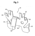
- the metal part 14 (see FIG. 3 ) is formed from a flat metal plate and has a base portion 36 from which extend in a first direction inclined latching hooks 38, two inclined in an opposite second direction positioning portions 40 and two metal claws 42 extending in the same direction as the positioning 40th are inclined. Furthermore, the metal part 14 has a tongue 44 bent over in the first direction.
- FIG. 4 It is shown how the metal part 14 is inserted through the opening 30 in the edge clip part 20 of the plastic part 12.
- the FIGS. 5a, 5b and 5c When inserting the metal part 14 of the holding portion 32 of the Kantenklippteils 20 serves as a stop, and the base portion 36 of the metal part 14 is latched behind the hook-like formed holding portion 32 (FIGS. FIG. 5a ). As a result, the movement of the metal part 14 in the insertion direction A is limited.
- the latching hooks 38 latch into the latching windows 34 of the plastic part 12, so that the metal part 14 is also stuck with respect to the direction B opposite to the insertion direction ( FIG. 5b ).
- the positioning portions 40 press the metal part 14 in the edge clip part 20 in a predetermined position and ensure that the metal part 14 maintains this defined position ( FIG. 5c ).
- the tongue 44 of the metal part 14 protrudes into the cable lock 18 and acts directly on the cable strap 16 when this is inserted into the cable lock 18.
- the cable band 16 has a sawtooth-like profile 16a in a known manner. Due to the much higher compared to the material of the plastic part 12 rigidity of the metal tongue 44 is also at very high pull-out forces the cable strap 16 still held securely in the cable lock 18.
- FIG. 7 finally shows the fastening device after it has been plugged onto the edge 10 of the base part (wherein the first leg 22 of the Kantenklippteils 20 is shown in the undeflected state).
- the facing away from the cable lock 18 sheet metal claws 42 engage directly on the second leg 24 facing side of the base part, thus preventing inadvertent withdrawal of the fastening device of the edge 10 of the base part.
- either the cable or the wiring harness can be fixed first by folding and inserting the cable strap 16 into the cable lock 18 on the fastening device, or the fastening device is first attached to the edge 10 on the base part by fitting it to the edge 10.
Abstract
Description
- Die Erfindung betrifft eine Befestigungsvorrichtung für Kabel.
- Insbesondere in der Automobilindustrie sind unterschiedliche Befestigungsvorrichtungen bekannt, mit denen einzelne Kabel oder Kabelbäume z.B. an einem Blechteil fixiert werden können. Zur Anbringung der Befestigungsvorrichtung am Blechteil, oder allgemein an einem Basisteil, weist dieses in der Regel eine oder mehrere Öffnungen auf, in die Rastelemente der Befestigungsvorrichtung eingedrückt werden. Bei der Kabelverlegung besteht unter Umständen ein Bedarf nach einer Fixierung von Kabeln an oder entlang einer Kante eines Basisteils.
- Die Erfindung schafft eine kostengünstig herstellbare und einfach zu montierende Befestigungsvorrichtung, die eine sehr zuverlässige Kabelfixierung relativ zu einer Kante eines Basisteils ermöglicht.
- Gemäß der Erfindung umfaßt eine Befestigungsvorrichtung für Kabel einen Kantenklippteil zur Anbringung der Befestigungsvorrichtung an einer Kante eines Basisteils, ein in den Kantenklippteil einsetzbares Metallteil, ein Kabelbandschloß und ein in das Kabelbandschloß einführbares Kabelband, wobei das Metallteil eine in das Kabelbandschloß hineinragende Zunge aufweist, die bei eingeführtem Kabelband am Kabelband angreift. Die erfindungsgemäße Befestigungsvorrichtung wird - mit oder ohne eingebundenem Kabel - einfach auf die Kante des Basisteils aufgesteckt. Die Metallzunge, die nach Einführung des Kabelbands in das Kabelbandschloß am Kabelband angreift, sorgt für eine im Vergleich zu Kabelbindern mit einem herkömmlichen Kabelbandrastmechanismus aus reinem Kunststoff für eine deutlich erhöhte Auszugskraft, d.h. das Kabelband ist besser gegen unbeabsichtigten Auszug gesichert. Dies läßt sich dadurch erklären, daß bei herkömmlichen Kabelbindern Kabelband und Kabelbandschloß aus dem gleichen Kunststoff gefertigt werden, der einerseits eine ausreichend leichte Verbiegung des Kabelbands erlaubt, andererseits aber gerade aufgrund dieser Nachgiebigkeit die Auszugskraft begrenzt.
- Vorzugsweise sind der Kantenklippteil, das Kabelbandschloß und das Kabelband einstückig aus (demselben) Kunststoff hergestellt, so daß die Zahl der Einzelteile der Befestigungsvorrichtung auf ein Minimum reduziert ist. Nur das Metallteil wird separat gefertigt.
- Für einen besonders einfachen Zusammenbau der Befestigungsvorrichtung weist der Kantenklippteil eine Öffnung auf, durch die das Metallteil in den Kantenklippteil eingesetzt werden kann. Die Öffnung ist vorzugsweise auf der Seite des Kantenklippteils vorgesehen, die einem Aufsteckspalt des Kantenklippteils entgegengesetzt ist.
- Um einem unbeabsichtigten Abzug der Befestigungsvorrichtung von der Kante des Basisteils effektiv entgegenzuwirken, weist das Metallteil wenigstens eine Blechkralle auf, die bei aufgesteckter Befestigungsvorrichtung direkt am Basisteil angreift. Das Metallteil hat in diesem Fall eine Doppelfunktion: zum einen hält die Zunge das Kabelband fest, zum anderen arretiert die Blechkralle die Befestigungsvorrichtung am Basisteil.
- Zur Positionierung und zur sicheren Befestigung des Metallteils im Kantenklippteil weist das Metallteil wenigstens einen Positionierabschnitt, der das Metallteil im Kantenklippteil in einer definierten Lage hält, bzw. wenigstens einen Rasthaken auf, der in ein korrespondierendes Rastfenster des Kantenklippteils einrastet.
- Um den Einschubweg für das Metallteil im Kantenklippteil zu begrenzen, weist der Kantenklippteil einen Halteabschnitt auf, der einen Anschlag für das Metallteil bildet. Vorzugsweise ist der Halteabschnitt des Kantenklippteils hakenartig ausgebildet, und ein Abschnitt des Metallteils verrastet hinter dem hakenartigen Halteabschnitt.
- Für bestimmte Anwendungen ist es vorteilhaft, daß sich das Kabelband vor Einführung in das Kabelbandschloß im wesentlichen senkrecht zu einer Aufsteckrichtung erstreckt, die durch den Kantenklippteil definiert ist.
- Weitere Merkmale und Vorteile der Erfindung ergeben sich aus der nachfolgenden Beschreibung einer bevorzugten Ausführungsform unter Bezugnahme auf die beigefügten Zeichnungen. In den Zeichnungen zeigen:
-
Figur 1 eine Explosionsdarstellung einer erfindungsgemäßen Befestigungsvorrichtung; -
Figur 2 eine perspektivische Ansicht des Kantenklippteils; -
Figur 3 eine perspektivische Ansicht des Metallteils; -
Figur 4 eine perspektivische Ansicht des Kantenklippteils und des Metallteils; -
Figuren 5a, 5b ,5c verschiedene perspektivische Ansichten des Kantenklippteils mit eingesetzten Metallteil; -
Figur 6 eine Schnittansicht der Befestigungsvorrichtung mit eingesetztem Metallteil und eingeführtem Kabelband; und -
Figur 7 eine Seitenansicht der aufgesteckten Befestigungsvorrichtung. - In
Figur 1 sind die Einzelteile einer erfindungsgemäßen Befestigungsvorrichtung gezeigt, die zur Fixierung eines Kabels oder Kabelbaums an einer Montagekante 10 eines Basisteils dient. Das Basisteil kann z.B. ein Blechteil oder ein Karosserieteil eines Kraftfahrzeugs sein. Neben einem Kunststoffteil 12, dessen Aufbau noch genauer erläutert wird, weist die Befestigungsvorrichtung noch ein Metallteil 14 auf. - Das einstückig ausgeführte Kunststoffteil 12 kann in drei Funktionsabschnitte unterteilt werden: ein Kabelband 16, das um das bzw. die zu fixierenden Kabel gelegt wird; ein Kabelbandschloß 18, in das das Kabelband 16 zur Fixierung des bzw. der Kabel eingeführt wird; und einen Kantenklippteil 20 zum Anbringen der Befestigungsvorrichtung an der Kante 10 des Basisteils.
- In
Figur 2 sind weitere Details des Kunststoffteils 12 zu erkennen. Das Kabelbandschloß 18 ist im wesentlichen durch einen beidseitig offenen Schacht gebildet, von dem sich das Kabelband 16 im wesentlichen senkrecht erstreckt. Auf der anderen Seite des Kabelbandschlosses 18 schließt sich der U-förmige Kantenklippteil 20 mit zwei Schenkeln 22, 24 an. Die Schenkel 22, 24 definieren einen Aufsteckspalt 26 und sind auf der entgegengesetzten Seite durch Verbindungsabschnitte 28 miteinander verbunden, die als Anschlag für die Kante 10 des Basisteils dienen. Der dem Kabelbandschloß 18 abgewandte erste Schenkel 22 weist einen abgewinkelten Abschnitt 22a auf, der zusammen mit dem abgeschrägten Ende 24a des zweiten Schenkels 24 das Aufstecken auf die Kante 10 erleichtert. Außerdem ist der erste Schenkel 22 so ausgebildet, daß er elastisch auslenkbar ist und nach dem Aufstecken auf die Kante 10 eine Federkraft auf diese ausübt. - Des weiteren weist das Kunststoffteil 12 auf der dem Aufsteckspalt 26 entgegengesetzten Seite eine Öffnung 30 auf, durch die das in
Figur 3 einzeln gezeigte Metallteil 14 in den Kantenklippteil 20 eingesetzt werden kann. Der Kantenklippteil 20 ist speziell auf das Metallteil 14 abgestimmt und hat einen hakenartig ausgebildeten Halteabschnitt 32, der als Anschlag für das Metallteil 14 dient, sowie zwei Rastfenster 34, deren Bedeutung noch erläutert wird. - Das Metallteil 14 (siehe
Figur 3 ) ist aus einer flachen Metallplatte geformt und weist einen Basisabschnitt 36 auf, von dem sich zwei in eine erste Richtung geneigte Rasthaken 38, zwei in eine entgegengesetzte zweite Richtung geneigte Positionierabschnitte 40 und zwei Blechkrallen 42 erstrecken, die in die gleiche Richtung wie die Positionierabschnitte 40 geneigt sind. Ferner weist das Metallteil 14 eine in der ersten Richtung umgebogene Zunge 44 auf. - In
Figur 4 ist gezeigt, wie das Metallteil 14 durch die Öffnung 30 in den Kantenklippteil 20 des Kunststoffteils 12 eingesetzt wird. DieFiguren 5a, 5b und5c zeigen das Kunststoffteil 12 mit vollständig eingesetztem Metallteil 14. Beim Einschieben des Metallteils 14 dient der Halteabschnitt 32 des Kantenklippteils 20 als Anschlag, und der Basisabschnitt 36 des Metallteil 14 verrastet hinter dem hakenartigen ausgebildeten Halteabschnitt 32 (Figur 5a ). Dadurch wird die Bewegung des Metallteils 14 in Einsetzrichtung A begrenzt. - Außerdem rasten beim Einschieben des Metallteils 14 die Rasthaken 38 in die Rastfenster 34 des Kunststoffteils 12 ein, so daß das Metallteil 14 auch bezüglich der der Einsetzrichtung A entgegengesetzten Richtung B festsitzt (
Figur 5b ). Die Positionierabschnitte 40 drücken das Metallteil 14 im Kantenklippteil 20 in eine vorbestimmte Lage und sorgen dafür, daß das Metallteil 14 diese definierte Lage beibehält (Figur 5c ). - In
Figur 6 ist zu erkennen, daß die Zunge 44 des Metallteils 14 in das Kabelbandschloß 18 hineinragt und direkt am Kabelband 16 angreift, wenn dieses in das Kabelbandschloß 18 eingeführt ist. Das Kabelband 16 weist in bekannter Weise ein sägezahnartiges Profil 16a auf. Aufgrund der im Vergleich zum Material des Kunststoffteils 12 viel höheren Steifigkeit der Metallzunge 44 wird auch bei sehr hohen Auszugskräften das Kabelband 16 noch sicher im Kabelbandschloß 18 gehalten. -
Figur 7 zeigt schließlich die Befestigungsvorrichtung, nachdem sie auf die Kante 10 des Basisteils aufgesteckt wurde (wobei der erste Schenkel 22 des Kantenklippteils 20 im nicht ausgelenkten Zustand dargestellt ist). Die vom Kabelbandschloß 18 weggewandten Blechkrallen 42 greifen unmittelbar an der dem zweiten Schenkel 24 zugewandten Seite des Basisteils an und verhindern so einen unbeabsichtigten Abzug der Befestigungsvorrichtung von der Kante 10 des Basisteils. - Bei der Kabelverlegung kann den Umständen entsprechend entweder zuerst das Kabel bzw. der Kabelbaum durch Umlegen und Einführen des Kabelbands 16 in das Kabelbandschloß 18 an der Befestigungsvorrichtung fixiert werden, oder es wird zuerst die Befestigungsvorrichtung durch Aufstecken auf die Kante 10 am Basisteil angebracht.
Claims (10)
- Befestigungsvorrichtung für Kabel, mit einem Kantenklippteil (20) zur Anbringung der Befestigungsvorrichtung an einer Kante (10) eines Basisteils, einem in den Kantenklippteil (20) einsetzbaren Metallteil (14), einem Kabelbandschloß (18) und einem in das Kabelbandschloß (18) einführbaren Kabelband (16), wobei das Metallteil (14) eine in das Kabelbandschloß (18) hineinragende Zunge (44) aufweist, die bei eingeführtem Kabelband (16) am Kabelband (16) angreift.
- Befestigungsvorrichtung nach Anspruch 1, dadurch gekennzeichnet, daß der Kantenklippteil (20), das Kabelbandschloß (18) und das Kabelband (16) einstückig aus Kunststoff hergestellt sind.
- Befestigungsvorrichtung nach Anspruch 1 oder 2, dadurch gekennzeichnet, daß der Kantenklippteil (20) eine Öffnung (30) aufweist, durch die das Metallteil (14) in den Kantenklippteil (20) eingesetzt werden kann.
- Befestigungsvorrichtung nach Anspruch 3, dadurch gekennzeichnet, daß der Kantenklippteil (20) auf einer Seite einen Aufsteckspalt (26) aufweist und die Öffnung (30) für das Metallteil (14) auf der entgegengesetzten Seite vorgesehen ist.
- Befestigungsvorrichtung nach einem der vorhergehenden Ansprüche, dadurch gekennzeichnet, daß das Metallteil (14) wenigstens eine Blechkralle (42) aufweist, die bei aufgesteckter Befestigungsvorrichtung direkt am Basisteil angreift.
- Befestigungsvorrichtung nach einem der vorhergehenden Ansprüche, dadurch gekennzeichnet, daß das Metallteil (14) wenigstens einen Positionierabschnitt (40) aufweist, der das Metallteil (14) im Kantenklippteil (20) in einer definierten Lage hält.
- Befestigungsvorrichtung nach einem der vorhergehenden Ansprüche, dadurch gekennzeichnet, daß das Metallteil (14) wenigstens einen Rasthaken (38) aufweist, der in ein korrespondierendes Rastfenster (34) des Kantenklippteils (20) einrastet.
- Befestigungsvorrichtung nach einem der vorhergehenden Ansprüche, dadurch gekennzeichnet, daß der Kantenklippteil (20) einen Halteabschnitt (32) aufweist, der einen Anschlag für das Metallteil (14) bildet.
- Befestigungsvorrichtung nach Anspruch 8, dadurch gekennzeichnet, daß der Halteabschnitt (32) des Kantenklippteils (20) hakenartig ausgebildet ist und ein Abschnitt (36) des Metallteils (14) hinter dem hakenartigen Halteabschnitt (32) verrastet.
- Befestigungsvorrichtung nach einem der vorhergehenden Ansprüche, dadurch gekennzeichnet, daß der Kantenklippteil (20) eine Aufsteckrichtung definiert und daß sich das Kabelband (16) vor Einführung in das Kabelbandschloß (18) im wesentlichen senkrecht zur Aufsteckrichtung erstreckt.
Applications Claiming Priority (1)
| Application Number | Priority Date | Filing Date | Title |
|---|---|---|---|
| DE202007000938U DE202007000938U1 (de) | 2007-01-22 | 2007-01-22 | Befestigungsvorrichtung für Kabel |
Publications (3)
| Publication Number | Publication Date |
|---|---|
| EP1947750A2 true EP1947750A2 (de) | 2008-07-23 |
| EP1947750A3 EP1947750A3 (de) | 2010-03-10 |
| EP1947750B1 EP1947750B1 (de) | 2013-07-03 |
Family
ID=37990057
Family Applications (1)
| Application Number | Title | Priority Date | Filing Date |
|---|---|---|---|
| EP07024138.5A Not-in-force EP1947750B1 (de) | 2007-01-22 | 2007-12-12 | Befestigungsvorrichtung für Kabel |
Country Status (7)
| Country | Link |
|---|---|
| US (1) | US7819365B2 (de) |
| EP (1) | EP1947750B1 (de) |
| JP (1) | JP5108500B2 (de) |
| KR (1) | KR20080069124A (de) |
| CN (1) | CN101232161B (de) |
| DE (1) | DE202007000938U1 (de) |
| ES (1) | ES2421177T3 (de) |
Cited By (1)
| Publication number | Priority date | Publication date | Assignee | Title |
|---|---|---|---|---|
| FR2995382A1 (fr) * | 2012-09-13 | 2014-03-14 | Leoni Wiring Systems France | Dispositif de fixation d'un cable sur un support |
Families Citing this family (37)
| Publication number | Priority date | Publication date | Assignee | Title |
|---|---|---|---|---|
| US7866005B2 (en) * | 2008-01-09 | 2011-01-11 | Panduit Corp. | Elastomeric releasable cable tie |
| US7959211B2 (en) * | 2008-08-25 | 2011-06-14 | Control Solutions LLC | Sensor installations for motorized vehicle doors |
| DE102008059360B4 (de) * | 2008-11-28 | 2014-10-09 | Trw Automotive Electronics & Components Gmbh | Befestigungsvorrichtung |
| CN102472415B (zh) * | 2009-07-07 | 2017-07-07 | 伊利诺斯工具制品有限公司 | 自定心的电缆扎带 |
| CN102055150A (zh) * | 2009-11-05 | 2011-05-11 | 鸿富锦精密工业(深圳)有限公司 | 线夹 |
| JP5478374B2 (ja) * | 2010-06-15 | 2014-04-23 | ポップリベット・ファスナー株式会社 | 結束具 |
| CN102298415A (zh) * | 2010-06-25 | 2011-12-28 | 鸿富锦精密工业(深圳)有限公司 | 束线装置 |
| JP5408068B2 (ja) * | 2010-08-05 | 2014-02-05 | 住友電装株式会社 | ワイヤハーネス用クリップおよびワイヤハーネス用クリップの車体取付方法 |
| US9340339B2 (en) * | 2011-09-30 | 2016-05-17 | Thomas & Betts International Llc | Cable tie with dissimilar material barb |
| EP2586334A1 (de) * | 2011-10-31 | 2013-05-01 | Elfa International AB | Haltevorrichtung |
| JP5957781B2 (ja) * | 2012-02-17 | 2016-07-27 | 矢崎総業株式会社 | 摺動式クランプ及びクランプ対象部材取り付け構造 |
| CN103311850B (zh) * | 2013-06-14 | 2016-03-16 | 安徽江淮汽车股份有限公司 | 一种翼型簧和一种线束固定异型夹 |
| FR3014531B1 (fr) | 2013-12-09 | 2016-05-06 | Trw Automotive Elect & Components Gmbh | Dispositif de fixation pour cable |
| EP3015317B1 (de) * | 2014-10-30 | 2018-12-05 | Nexans | Anordnung zum Befestigen eines langgestreckten Gegenstands in einem Kraftfahrzeug |
| WO2016088209A1 (ja) * | 2014-12-02 | 2016-06-09 | ヘラマンタイトン株式会社 | クリップ |
| DE102015102825B3 (de) * | 2015-02-27 | 2016-04-28 | Lisa Dräxlmaier GmbH | Klemme |
| DE102015211271B3 (de) * | 2015-06-18 | 2016-11-17 | Ford Global Technologies, Llc | Befestigungseinrichtung für ein Kabel |
| DE202015104952U1 (de) * | 2015-09-17 | 2016-12-20 | Pfm Medical Ag | Bindevorrichtung |
| US10202995B2 (en) * | 2015-10-27 | 2019-02-12 | A. Raymond Et Cie | Self-locking edge clip fastener |
| CN105346484A (zh) * | 2015-11-12 | 2016-02-24 | 安徽江淮汽车股份有限公司 | 一种钣金卡总成 |
| CN105680381A (zh) * | 2016-03-08 | 2016-06-15 | 中车青岛四方机车车辆股份有限公司 | 车辆的线缆固定装置及具有其的车辆 |
| JP6546699B2 (ja) * | 2016-05-18 | 2019-07-17 | 株式会社パイオラックス | クリップ |
| US9986865B2 (en) * | 2016-09-19 | 2018-06-05 | Christopher Morris | Retrofittable system and apparatus for hanging articles on pre-installed supports |
| JP1590183S (de) * | 2017-03-06 | 2017-11-06 | ||
| CN108695782A (zh) * | 2017-04-07 | 2018-10-23 | 法雷奥照明湖北技术中心有限公司 | 线束保持装置 |
| US11209030B2 (en) | 2017-08-09 | 2021-12-28 | Hellermanntyton Corporation | Six way bundle flange mount |
| JP1612261S (de) * | 2017-10-26 | 2018-08-27 | ||
| DE102018127519A1 (de) * | 2018-11-05 | 2020-05-07 | Illinois Tool Works Inc. | Befestigungsclip zur Befestigung eines Anbauteils an einer Trägerkante |
| US10851820B2 (en) | 2018-12-28 | 2020-12-01 | A. Raymond Et Cie | Self-locking edge clip assembly |
| US11566452B1 (en) * | 2019-06-04 | 2023-01-31 | Jared Waddle | Cable tie restraining apparatus |
| US11242945B2 (en) * | 2019-09-24 | 2022-02-08 | Autronic Plastics, Inc. | Hanger for messenger wire |
| USD944632S1 (en) | 2019-10-17 | 2022-03-01 | A. Raymond Et Cie | Edge clip |
| US11603873B2 (en) * | 2020-09-30 | 2023-03-14 | A. Raymond Et Cie | Heavy duty fastening assembly with installation verification |
| US11420571B1 (en) | 2021-02-25 | 2022-08-23 | A. Raymond Et Cie | Serviceable edge clip assembly |
| CN113483157A (zh) | 2021-08-06 | 2021-10-08 | 海尔曼太通(无锡)电器配件有限公司 | 一种快速拆装管夹 |
| EP4131687A1 (de) | 2021-08-06 | 2023-02-08 | HellermannTyton GmbH | Kantenclip |
| DE202021105021U1 (de) | 2021-09-17 | 2022-12-22 | Hellermanntyton Gmbh | Modularer Kantenclip |
Citations (6)
| Publication number | Priority date | Publication date | Assignee | Title |
|---|---|---|---|---|
| US1005269A (en) | 1910-06-15 | 1911-10-10 | Security Envelope Fastener Company | Staple-setting tool. |
| US3113754A (en) | 1962-09-18 | 1963-12-10 | United Carr Fastener Corp | Wiring clip |
| US3632070A (en) | 1970-02-09 | 1972-01-04 | Panduit Corp | Right-angle mounting bracket |
| JPH11196522A (ja) | 1997-12-26 | 1999-07-21 | Sumitomo Wiring Syst Ltd | 線状体保持具 |
| DE10332376A1 (de) | 2003-07-17 | 2005-02-03 | Volkswagen Ag | Verbindung zwischen einem Halteelement zum Halten eines Leitungs- und/oder Kabelstranges und zumindest einem Trägerelement an einem Fahrzeug |
| DE202006001743U1 (de) | 2006-02-04 | 2006-04-13 | T.B. Dienstleistungen Gmbh | Clip zum Festlegen eines Kabels |
Family Cites Families (16)
| Publication number | Priority date | Publication date | Assignee | Title |
|---|---|---|---|---|
| GB1005269A (en) * | 1962-11-01 | 1965-09-22 | Carr Fastener Co Ltd | Fastener device for securing an article to a support |
| US3192584A (en) * | 1963-04-17 | 1965-07-06 | Fmc Corp | Strap coupler |
| US3562870A (en) * | 1969-04-04 | 1971-02-16 | Electrovert Mfg Co Ltd | Cable tie with metal insert having two pawls |
| US3875618A (en) * | 1973-12-10 | 1975-04-08 | Fastway Fasteners | Bundling tie |
| US4498507A (en) * | 1983-06-28 | 1985-02-12 | Minnesota Mining And Manufacturing Company | Cable tie |
| JPS63170605U (de) | 1987-04-25 | 1988-11-07 | ||
| US4993669A (en) * | 1990-01-04 | 1991-02-19 | Tyton Corporation | Bundle tie |
| DE69823617D1 (de) * | 1997-12-01 | 2004-06-09 | Thomas & Betts Int | Verbesserter Kabelbinder mit Verschlusskopf und getrenntem Bindestreifen |
| US6532631B2 (en) * | 2000-02-24 | 2003-03-18 | Panduit Corp. | Four piece cable tie |
| US6550723B2 (en) * | 2000-12-21 | 2003-04-22 | International Business Machines Corporation | Removable cable tie |
| DE20202548U1 (de) | 2002-02-14 | 2002-05-02 | Vogt Gmbh & Co Hermann | Befestigungskralle |
| US6807714B2 (en) * | 2002-03-04 | 2004-10-26 | Panduit Corp. | Cable tie having stepped down strap body teeth |
| EP1625083A4 (de) * | 2003-05-22 | 2007-04-25 | Physical Systems | Kabelbinder |
| DE10340571B3 (de) * | 2003-09-01 | 2005-04-21 | Newfrey Llc, Newark | Klemme zum Halten von flachen Gegenständen |
| JP4757453B2 (ja) * | 2004-04-09 | 2011-08-24 | 大和化成工業株式会社 | クランプの取付構造 |
| DE202005019375U1 (de) | 2005-12-05 | 2006-02-16 | Takata-Petri (Ulm) Gmbh | Airbagmodul für ein Kraftfahrzeug |
-
2007
- 2007-01-22 DE DE202007000938U patent/DE202007000938U1/de not_active Expired - Lifetime
- 2007-12-12 EP EP07024138.5A patent/EP1947750B1/de not_active Not-in-force
- 2007-12-12 ES ES07024138T patent/ES2421177T3/es active Active
- 2007-12-27 JP JP2007336777A patent/JP5108500B2/ja not_active Expired - Fee Related
-
2008
- 2008-01-18 KR KR1020080005659A patent/KR20080069124A/ko not_active Application Discontinuation
- 2008-01-21 CN CN2008100046052A patent/CN101232161B/zh not_active Expired - Fee Related
- 2008-01-22 US US12/009,751 patent/US7819365B2/en not_active Expired - Fee Related
Patent Citations (6)
| Publication number | Priority date | Publication date | Assignee | Title |
|---|---|---|---|---|
| US1005269A (en) | 1910-06-15 | 1911-10-10 | Security Envelope Fastener Company | Staple-setting tool. |
| US3113754A (en) | 1962-09-18 | 1963-12-10 | United Carr Fastener Corp | Wiring clip |
| US3632070A (en) | 1970-02-09 | 1972-01-04 | Panduit Corp | Right-angle mounting bracket |
| JPH11196522A (ja) | 1997-12-26 | 1999-07-21 | Sumitomo Wiring Syst Ltd | 線状体保持具 |
| DE10332376A1 (de) | 2003-07-17 | 2005-02-03 | Volkswagen Ag | Verbindung zwischen einem Halteelement zum Halten eines Leitungs- und/oder Kabelstranges und zumindest einem Trägerelement an einem Fahrzeug |
| DE202006001743U1 (de) | 2006-02-04 | 2006-04-13 | T.B. Dienstleistungen Gmbh | Clip zum Festlegen eines Kabels |
Cited By (1)
| Publication number | Priority date | Publication date | Assignee | Title |
|---|---|---|---|---|
| FR2995382A1 (fr) * | 2012-09-13 | 2014-03-14 | Leoni Wiring Systems France | Dispositif de fixation d'un cable sur un support |
Also Published As
| Publication number | Publication date |
|---|---|
| US20080229550A1 (en) | 2008-09-25 |
| KR20080069124A (ko) | 2008-07-25 |
| CN101232161B (zh) | 2012-01-11 |
| DE202007000938U1 (de) | 2007-04-19 |
| EP1947750A3 (de) | 2010-03-10 |
| JP5108500B2 (ja) | 2012-12-26 |
| US7819365B2 (en) | 2010-10-26 |
| ES2421177T3 (es) | 2013-08-29 |
| EP1947750B1 (de) | 2013-07-03 |
| JP2008182880A (ja) | 2008-08-07 |
| CN101232161A (zh) | 2008-07-30 |
Similar Documents
| Publication | Publication Date | Title |
|---|---|---|
| EP1947750B1 (de) | Befestigungsvorrichtung für Kabel | |
| EP2371046B1 (de) | Drahtbefestigungsvorrichtung | |
| EP2881597B1 (de) | Befestigungsvorrichtung für Kabel | |
| WO2009033531A1 (de) | Vorrichtung zum befestigen eines anbauteiles an einem trägerteil | |
| DE10340571B3 (de) | Klemme zum Halten von flachen Gegenständen | |
| EP1810896A2 (de) | Halteklammer für einen Regensensor | |
| EP0818071A1 (de) | Vorrichtung zum halten und führen von kabeln und schläuchen in schaltschränken | |
| DE10357448A1 (de) | Rastverbindungsteil und Gassackmodul | |
| DE102010056412A1 (de) | Anordnung eines Anbauteils an einem Trägerbauteil in einem Innenraum eines Kraftfahrzeugs | |
| DE102012003617B4 (de) | Vorrichtung aus einem Gehäuse für ein Steuergerät und einem Befestigungselement | |
| EP2432666A2 (de) | Befestigungselement und verfahren zum befestigen eines gassacks eines fahrzeuginsassen-rückhaltesystems an einer fahrzeugstruktur | |
| DE19921351C2 (de) | Kabelstrangbefestigungsanordnung | |
| EP1687164B1 (de) | Aggregateträger mit integrierter schlossbefestigung für eine kraftfahrzeugtür | |
| WO2008098715A1 (de) | Befestigungselement für das spannband einer seitenairbaganordnung | |
| DE60125900T2 (de) | Halteclip zur Befestigung von Leisten | |
| DE102011114030B4 (de) | Federbefestigungsclip | |
| DE102018127519A1 (de) | Befestigungsclip zur Befestigung eines Anbauteils an einer Trägerkante | |
| DE602004005534T2 (de) | Elastisches Befestigungselement mit einer Verdrehsicherung | |
| DE102010018983A1 (de) | Befestigung für eine Komponente, insbesondere an der Karosserie eines Kraftfahrzeugs | |
| DE10332376B4 (de) | Verbindung zwischen einem Halteelement zum Halten eines Leitungs- und/oder Kabelstranges und zumindest einem Trägerelement an einem Fahrzeug | |
| DE102005012714A1 (de) | Clipsystem zur Befestigung eines Anbauteils an einem Trägerteil | |
| DE19809902B4 (de) | Außenrückblickspiegel | |
| EP1371530B1 (de) | Befestigungseinrichtung | |
| DE102019123399B4 (de) | Fahrzeugkomponente mit wenigstens einer Montageklammer | |
| DE102023000244B3 (de) | Haltevorrichtung zum Halten eines Steuergeräts an einem Rohbauteil eines Kraftwagens |
Legal Events
| Date | Code | Title | Description |
|---|---|---|---|
| PUAI | Public reference made under article 153(3) epc to a published international application that has entered the european phase |
Free format text: ORIGINAL CODE: 0009012 |
|
| AK | Designated contracting states |
Kind code of ref document: A2 Designated state(s): AT BE BG CH CY CZ DE DK EE ES FI FR GB GR HU IE IS IT LI LT LU LV MC MT NL PL PT RO SE SI SK TR |
|
| AX | Request for extension of the european patent |
Extension state: AL BA HR MK RS |
|
| PUAL | Search report despatched |
Free format text: ORIGINAL CODE: 0009013 |
|
| AK | Designated contracting states |
Kind code of ref document: A3 Designated state(s): AT BE BG CH CY CZ DE DK EE ES FI FR GB GR HU IE IS IT LI LT LU LV MC MT NL PL PT RO SE SI SK TR |
|
| AX | Request for extension of the european patent |
Extension state: AL BA HR MK RS |
|
| 17P | Request for examination filed |
Effective date: 20100518 |
|
| AKX | Designation fees paid |
Designated state(s): AT BE BG CH CY CZ DE DK EE ES FI FR GB GR HU IE IS IT LI LT LU LV MC MT NL PL PT RO SE SI SK TR |
|
| GRAP | Despatch of communication of intention to grant a patent |
Free format text: ORIGINAL CODE: EPIDOSNIGR1 |
|
| GRAS | Grant fee paid |
Free format text: ORIGINAL CODE: EPIDOSNIGR3 |
|
| GRAA | (expected) grant |
Free format text: ORIGINAL CODE: 0009210 |
|
| AK | Designated contracting states |
Kind code of ref document: B1 Designated state(s): AT BE BG CH CY CZ DE DK EE ES FI FR GB GR HU IE IS IT LI LT LU LV MC MT NL PL PT RO SE SI SK TR |
|
| REG | Reference to a national code |
Ref country code: GB Ref legal event code: FG4D Free format text: NOT ENGLISH |
|
| REG | Reference to a national code |
Ref country code: AT Ref legal event code: REF Ref document number: 620222 Country of ref document: AT Kind code of ref document: T Effective date: 20130715 Ref country code: CH Ref legal event code: EP |
|
| REG | Reference to a national code |
Ref country code: IE Ref legal event code: FG4D Free format text: LANGUAGE OF EP DOCUMENT: GERMAN |
|
| REG | Reference to a national code |
Ref country code: DE Ref legal event code: R096 Ref document number: 502007011977 Country of ref document: DE Effective date: 20130829 Ref country code: ES Ref legal event code: FG2A Ref document number: 2421177 Country of ref document: ES Kind code of ref document: T3 Effective date: 20130829 |
|
| PG25 | Lapsed in a contracting state [announced via postgrant information from national office to epo] |
Ref country code: SI Free format text: LAPSE BECAUSE OF FAILURE TO SUBMIT A TRANSLATION OF THE DESCRIPTION OR TO PAY THE FEE WITHIN THE PRESCRIBED TIME-LIMIT Effective date: 20130703 |
|
| REG | Reference to a national code |
Ref country code: NL Ref legal event code: VDEP Effective date: 20130703 |
|
| REG | Reference to a national code |
Ref country code: LT Ref legal event code: MG4D |
|
| PG25 | Lapsed in a contracting state [announced via postgrant information from national office to epo] |
Ref country code: PT Free format text: LAPSE BECAUSE OF FAILURE TO SUBMIT A TRANSLATION OF THE DESCRIPTION OR TO PAY THE FEE WITHIN THE PRESCRIBED TIME-LIMIT Effective date: 20131104 Ref country code: IS Free format text: LAPSE BECAUSE OF FAILURE TO SUBMIT A TRANSLATION OF THE DESCRIPTION OR TO PAY THE FEE WITHIN THE PRESCRIBED TIME-LIMIT Effective date: 20131103 Ref country code: LT Free format text: LAPSE BECAUSE OF FAILURE TO SUBMIT A TRANSLATION OF THE DESCRIPTION OR TO PAY THE FEE WITHIN THE PRESCRIBED TIME-LIMIT Effective date: 20130703 Ref country code: CY Free format text: LAPSE BECAUSE OF FAILURE TO SUBMIT A TRANSLATION OF THE DESCRIPTION OR TO PAY THE FEE WITHIN THE PRESCRIBED TIME-LIMIT Effective date: 20130626 Ref country code: SE Free format text: LAPSE BECAUSE OF FAILURE TO SUBMIT A TRANSLATION OF THE DESCRIPTION OR TO PAY THE FEE WITHIN THE PRESCRIBED TIME-LIMIT Effective date: 20130703 |
|
| PG25 | Lapsed in a contracting state [announced via postgrant information from national office to epo] |
Ref country code: PL Free format text: LAPSE BECAUSE OF FAILURE TO SUBMIT A TRANSLATION OF THE DESCRIPTION OR TO PAY THE FEE WITHIN THE PRESCRIBED TIME-LIMIT Effective date: 20130703 Ref country code: GR Free format text: LAPSE BECAUSE OF FAILURE TO SUBMIT A TRANSLATION OF THE DESCRIPTION OR TO PAY THE FEE WITHIN THE PRESCRIBED TIME-LIMIT Effective date: 20131004 Ref country code: FI Free format text: LAPSE BECAUSE OF FAILURE TO SUBMIT A TRANSLATION OF THE DESCRIPTION OR TO PAY THE FEE WITHIN THE PRESCRIBED TIME-LIMIT Effective date: 20130703 Ref country code: LV Free format text: LAPSE BECAUSE OF FAILURE TO SUBMIT A TRANSLATION OF THE DESCRIPTION OR TO PAY THE FEE WITHIN THE PRESCRIBED TIME-LIMIT Effective date: 20130703 Ref country code: NL Free format text: LAPSE BECAUSE OF FAILURE TO SUBMIT A TRANSLATION OF THE DESCRIPTION OR TO PAY THE FEE WITHIN THE PRESCRIBED TIME-LIMIT Effective date: 20130703 |
|
| PG25 | Lapsed in a contracting state [announced via postgrant information from national office to epo] |
Ref country code: CY Free format text: LAPSE BECAUSE OF FAILURE TO SUBMIT A TRANSLATION OF THE DESCRIPTION OR TO PAY THE FEE WITHIN THE PRESCRIBED TIME-LIMIT Effective date: 20130703 |
|
| PG25 | Lapsed in a contracting state [announced via postgrant information from national office to epo] |
Ref country code: SK Free format text: LAPSE BECAUSE OF FAILURE TO SUBMIT A TRANSLATION OF THE DESCRIPTION OR TO PAY THE FEE WITHIN THE PRESCRIBED TIME-LIMIT Effective date: 20130703 Ref country code: RO Free format text: LAPSE BECAUSE OF FAILURE TO SUBMIT A TRANSLATION OF THE DESCRIPTION OR TO PAY THE FEE WITHIN THE PRESCRIBED TIME-LIMIT Effective date: 20130703 Ref country code: CZ Free format text: LAPSE BECAUSE OF FAILURE TO SUBMIT A TRANSLATION OF THE DESCRIPTION OR TO PAY THE FEE WITHIN THE PRESCRIBED TIME-LIMIT Effective date: 20130703 Ref country code: EE Free format text: LAPSE BECAUSE OF FAILURE TO SUBMIT A TRANSLATION OF THE DESCRIPTION OR TO PAY THE FEE WITHIN THE PRESCRIBED TIME-LIMIT Effective date: 20130703 Ref country code: DK Free format text: LAPSE BECAUSE OF FAILURE TO SUBMIT A TRANSLATION OF THE DESCRIPTION OR TO PAY THE FEE WITHIN THE PRESCRIBED TIME-LIMIT Effective date: 20130703 |
|
| PLBE | No opposition filed within time limit |
Free format text: ORIGINAL CODE: 0009261 |
|
| STAA | Information on the status of an ep patent application or granted ep patent |
Free format text: STATUS: NO OPPOSITION FILED WITHIN TIME LIMIT |
|
| 26N | No opposition filed |
Effective date: 20140404 |
|
| BERE | Be: lapsed |
Owner name: TRW AUTOMOTIVE ELECTRONICS & COMPONENTS G.M.B.H. Effective date: 20131231 |
|
| REG | Reference to a national code |
Ref country code: DE Ref legal event code: R097 Ref document number: 502007011977 Country of ref document: DE Effective date: 20140404 |
|
| REG | Reference to a national code |
Ref country code: CH Ref legal event code: PL |
|
| PG25 | Lapsed in a contracting state [announced via postgrant information from national office to epo] |
Ref country code: MC Free format text: LAPSE BECAUSE OF FAILURE TO SUBMIT A TRANSLATION OF THE DESCRIPTION OR TO PAY THE FEE WITHIN THE PRESCRIBED TIME-LIMIT Effective date: 20130703 Ref country code: LU Free format text: LAPSE BECAUSE OF FAILURE TO SUBMIT A TRANSLATION OF THE DESCRIPTION OR TO PAY THE FEE WITHIN THE PRESCRIBED TIME-LIMIT Effective date: 20131212 |
|
| REG | Reference to a national code |
Ref country code: IE Ref legal event code: MM4A |
|
| PG25 | Lapsed in a contracting state [announced via postgrant information from national office to epo] |
Ref country code: CH Free format text: LAPSE BECAUSE OF NON-PAYMENT OF DUE FEES Effective date: 20131231 Ref country code: LI Free format text: LAPSE BECAUSE OF NON-PAYMENT OF DUE FEES Effective date: 20131231 Ref country code: BE Free format text: LAPSE BECAUSE OF NON-PAYMENT OF DUE FEES Effective date: 20131231 Ref country code: IE Free format text: LAPSE BECAUSE OF NON-PAYMENT OF DUE FEES Effective date: 20131212 |
|
| REG | Reference to a national code |
Ref country code: AT Ref legal event code: MM01 Ref document number: 620222 Country of ref document: AT Kind code of ref document: T Effective date: 20131212 |
|
| PG25 | Lapsed in a contracting state [announced via postgrant information from national office to epo] |
Ref country code: AT Free format text: LAPSE BECAUSE OF NON-PAYMENT OF DUE FEES Effective date: 20131212 |
|
| PG25 | Lapsed in a contracting state [announced via postgrant information from national office to epo] |
Ref country code: TR Free format text: LAPSE BECAUSE OF FAILURE TO SUBMIT A TRANSLATION OF THE DESCRIPTION OR TO PAY THE FEE WITHIN THE PRESCRIBED TIME-LIMIT Effective date: 20130703 |
|
| PG25 | Lapsed in a contracting state [announced via postgrant information from national office to epo] |
Ref country code: BG Free format text: LAPSE BECAUSE OF FAILURE TO SUBMIT A TRANSLATION OF THE DESCRIPTION OR TO PAY THE FEE WITHIN THE PRESCRIBED TIME-LIMIT Effective date: 20130703 Ref country code: HU Free format text: LAPSE BECAUSE OF FAILURE TO SUBMIT A TRANSLATION OF THE DESCRIPTION OR TO PAY THE FEE WITHIN THE PRESCRIBED TIME-LIMIT; INVALID AB INITIO Effective date: 20071212 |
|
| PG25 | Lapsed in a contracting state [announced via postgrant information from national office to epo] |
Ref country code: MT Free format text: LAPSE BECAUSE OF FAILURE TO SUBMIT A TRANSLATION OF THE DESCRIPTION OR TO PAY THE FEE WITHIN THE PRESCRIBED TIME-LIMIT Effective date: 20130703 |
|
| REG | Reference to a national code |
Ref country code: FR Ref legal event code: PLFP Year of fee payment: 9 |
|
| REG | Reference to a national code |
Ref country code: GB Ref legal event code: 732E Free format text: REGISTERED BETWEEN 20160915 AND 20160921 |
|
| REG | Reference to a national code |
Ref country code: DE Ref legal event code: R082 Ref document number: 502007011977 Country of ref document: DE Representative=s name: MEISSNER BOLTE PATENTANWAELTE RECHTSANWAELTE P, DE Ref country code: DE Ref legal event code: R082 Ref document number: 502007011977 Country of ref document: DE Representative=s name: HGF EUROPE LLP, DE Ref country code: DE Ref legal event code: R082 Ref document number: 502007011977 Country of ref document: DE Representative=s name: HGF EUROPE LP, DE Ref country code: DE Ref legal event code: R082 Ref document number: 502007011977 Country of ref document: DE Representative=s name: HAUCK PATENTANWALTSPARTNERSCHAFT MBB, DE |
|
| REG | Reference to a national code |
Ref country code: FR Ref legal event code: PLFP Year of fee payment: 10 |
|
| PG25 | Lapsed in a contracting state [announced via postgrant information from national office to epo] |
Ref country code: IT Free format text: LAPSE BECAUSE OF NON-PAYMENT OF DUE FEES Effective date: 20151212 |
|
| REG | Reference to a national code |
Ref country code: DE Ref legal event code: R082 Ref document number: 502007011977 Country of ref document: DE Representative=s name: MEISSNER BOLTE PATENTANWAELTE RECHTSANWAELTE P, DE Ref country code: DE Ref legal event code: R082 Ref document number: 502007011977 Country of ref document: DE Representative=s name: HGF EUROPE LLP, DE Ref country code: DE Ref legal event code: R082 Ref document number: 502007011977 Country of ref document: DE Representative=s name: HAUCK PATENTANWALTSPARTNERSCHAFT MBB, DE Ref country code: DE Ref legal event code: R082 Ref document number: 502007011977 Country of ref document: DE Representative=s name: HGF EUROPE LP, DE Ref country code: DE Ref legal event code: R081 Ref document number: 502007011977 Country of ref document: DE Owner name: ILLINOIS TOOL WORKS INC. (N.D.GES.D. STAATES D, US Free format text: FORMER OWNER: TRW AUTOMOTIVE ELECTRONICS & COMPONENTS GMBH, 78315 RADOLFZELL, DE |
|
| PG25 | Lapsed in a contracting state [announced via postgrant information from national office to epo] |
Ref country code: IT Free format text: LAPSE BECAUSE OF NON-PAYMENT OF DUE FEES Effective date: 20151212 |
|
| PGRI | Patent reinstated in contracting state [announced from national office to epo] |
Ref country code: IT Effective date: 20170710 |
|
| REG | Reference to a national code |
Ref country code: GB Ref legal event code: 732E Free format text: REGISTERED BETWEEN 20170810 AND 20170816 |
|
| REG | Reference to a national code |
Ref country code: FR Ref legal event code: TP Owner name: ITW FASTENER PRODUCTS GMBH, DE Effective date: 20171002 |
|
| REG | Reference to a national code |
Ref country code: FR Ref legal event code: PLFP Year of fee payment: 11 |
|
| PGFP | Annual fee paid to national office [announced via postgrant information from national office to epo] |
Ref country code: ES Payment date: 20180102 Year of fee payment: 11 |
|
| PGFP | Annual fee paid to national office [announced via postgrant information from national office to epo] |
Ref country code: FR Payment date: 20181226 Year of fee payment: 12 Ref country code: GB Payment date: 20181227 Year of fee payment: 12 |
|
| REG | Reference to a national code |
Ref country code: DE Ref legal event code: R082 Ref document number: 502007011977 Country of ref document: DE Representative=s name: MEISSNER BOLTE PATENTANWAELTE RECHTSANWAELTE P, DE Ref country code: DE Ref legal event code: R082 Ref document number: 502007011977 Country of ref document: DE Representative=s name: HGF EUROPE LLP, DE Ref country code: DE Ref legal event code: R082 Ref document number: 502007011977 Country of ref document: DE Representative=s name: HGF EUROPE LP, DE |
|
| PGFP | Annual fee paid to national office [announced via postgrant information from national office to epo] |
Ref country code: IT Payment date: 20181220 Year of fee payment: 12 |
|
| REG | Reference to a national code |
Ref country code: ES Ref legal event code: PC2A Owner name: ILLINOIS TOOL WORKS INC. Effective date: 20190703 |
|
| REG | Reference to a national code |
Ref country code: DE Ref legal event code: R082 Ref document number: 502007011977 Country of ref document: DE Representative=s name: HGF EUROPE LLP, DE Ref country code: DE Ref legal event code: R082 Ref document number: 502007011977 Country of ref document: DE Representative=s name: HGF EUROPE LP, DE |
|
| REG | Reference to a national code |
Ref country code: ES Ref legal event code: FD2A Effective date: 20200203 |
|
| PG25 | Lapsed in a contracting state [announced via postgrant information from national office to epo] |
Ref country code: ES Free format text: LAPSE BECAUSE OF NON-PAYMENT OF DUE FEES Effective date: 20181213 |
|
| GBPC | Gb: european patent ceased through non-payment of renewal fee |
Effective date: 20191212 |
|
| PG25 | Lapsed in a contracting state [announced via postgrant information from national office to epo] |
Ref country code: IT Free format text: LAPSE BECAUSE OF NON-PAYMENT OF DUE FEES Effective date: 20191212 Ref country code: FR Free format text: LAPSE BECAUSE OF NON-PAYMENT OF DUE FEES Effective date: 20191231 Ref country code: GB Free format text: LAPSE BECAUSE OF NON-PAYMENT OF DUE FEES Effective date: 20191212 |
|
| PGFP | Annual fee paid to national office [announced via postgrant information from national office to epo] |
Ref country code: DE Payment date: 20201229 Year of fee payment: 14 |
|
| REG | Reference to a national code |
Ref country code: DE Ref legal event code: R119 Ref document number: 502007011977 Country of ref document: DE |
|
| PG25 | Lapsed in a contracting state [announced via postgrant information from national office to epo] |
Ref country code: DE Free format text: LAPSE BECAUSE OF NON-PAYMENT OF DUE FEES Effective date: 20220701 |