EP1945895B1 - Rahmenstruktur für türen oder fenster, für möbel oder beleuchtungen mit einer fläche, die auf gleicher ebene wie die wand ist - Google Patents
Rahmenstruktur für türen oder fenster, für möbel oder beleuchtungen mit einer fläche, die auf gleicher ebene wie die wand ist Download PDFInfo
- Publication number
- EP1945895B1 EP1945895B1 EP07705573A EP07705573A EP1945895B1 EP 1945895 B1 EP1945895 B1 EP 1945895B1 EP 07705573 A EP07705573 A EP 07705573A EP 07705573 A EP07705573 A EP 07705573A EP 1945895 B1 EP1945895 B1 EP 1945895B1
- Authority
- EP
- European Patent Office
- Prior art keywords
- wall
- section
- wing
- face
- main section
- Prior art date
- Legal status (The legal status is an assumption and is not a legal conclusion. Google has not performed a legal analysis and makes no representation as to the accuracy of the status listed.)
- Not-in-force
Links
- 230000000295 complement effect Effects 0.000 claims abstract description 56
- 239000011505 plaster Substances 0.000 claims description 5
- 230000001464 adherent effect Effects 0.000 claims description 2
- 239000011521 glass Substances 0.000 abstract description 4
- 239000011159 matrix material Substances 0.000 description 4
- 238000009434 installation Methods 0.000 description 3
- 239000000463 material Substances 0.000 description 3
- 229910052751 metal Inorganic materials 0.000 description 3
- 239000002184 metal Substances 0.000 description 3
- 239000007787 solid Substances 0.000 description 3
- 239000012780 transparent material Substances 0.000 description 3
- 239000004411 aluminium Substances 0.000 description 2
- 229910052782 aluminium Inorganic materials 0.000 description 2
- XAGFODPZIPBFFR-UHFFFAOYSA-N aluminium Chemical compound [Al] XAGFODPZIPBFFR-UHFFFAOYSA-N 0.000 description 2
- 230000006978 adaptation Effects 0.000 description 1
- 239000002131 composite material Substances 0.000 description 1
- 230000008878 coupling Effects 0.000 description 1
- 238000010168 coupling process Methods 0.000 description 1
- 238000005859 coupling reaction Methods 0.000 description 1
- 238000001125 extrusion Methods 0.000 description 1
- 238000012986 modification Methods 0.000 description 1
- 230000004048 modification Effects 0.000 description 1
- 239000011347 resin Substances 0.000 description 1
- 229920005989 resin Polymers 0.000 description 1
- 239000002023 wood Substances 0.000 description 1
Images


Classifications
-
- E—FIXED CONSTRUCTIONS
- E06—DOORS, WINDOWS, SHUTTERS, OR ROLLER BLINDS IN GENERAL; LADDERS
- E06B—FIXED OR MOVABLE CLOSURES FOR OPENINGS IN BUILDINGS, VEHICLES, FENCES OR LIKE ENCLOSURES IN GENERAL, e.g. DOORS, WINDOWS, BLINDS, GATES
- E06B1/00—Border constructions of openings in walls, floors, or ceilings; Frames to be rigidly mounted in such openings
- E06B1/04—Frames for doors, windows, or the like to be fixed in openings
- E06B1/52—Frames specially adapted for doors
-
- E—FIXED CONSTRUCTIONS
- E04—BUILDING
- E04B—GENERAL BUILDING CONSTRUCTIONS; WALLS, e.g. PARTITIONS; ROOFS; FLOORS; CEILINGS; INSULATION OR OTHER PROTECTION OF BUILDINGS
- E04B2/00—Walls, e.g. partitions, for buildings; Wall construction with regard to insulation; Connections specially adapted to walls
- E04B2/74—Removable non-load-bearing partitions; Partitions with a free upper edge
- E04B2/7407—Removable non-load-bearing partitions; Partitions with a free upper edge assembled using frames with infill panels or coverings only; made-up of panels and a support structure incorporating posts
- E04B2/7453—Removable non-load-bearing partitions; Partitions with a free upper edge assembled using frames with infill panels or coverings only; made-up of panels and a support structure incorporating posts with panels and support posts, extending from floor to ceiling
- E04B2/7455—Glazing details
-
- F—MECHANICAL ENGINEERING; LIGHTING; HEATING; WEAPONS; BLASTING
- F21—LIGHTING
- F21S—NON-PORTABLE LIGHTING DEVICES; SYSTEMS THEREOF; VEHICLE LIGHTING DEVICES SPECIALLY ADAPTED FOR VEHICLE EXTERIORS
- F21S8/00—Lighting devices intended for fixed installation
- F21S8/02—Lighting devices intended for fixed installation of recess-mounted type, e.g. downlighters
- F21S8/026—Lighting devices intended for fixed installation of recess-mounted type, e.g. downlighters intended to be recessed in a ceiling or like overhead structure, e.g. suspended ceiling
Definitions
- the present invention relates to the field of doors or windows, furniture and lightings having a surface on a same plane of a wall.
- the present invention relates to a combination of a frame, a panel and a wall according to the preamble of claim 1.
- frames are known defining an aperture for a door in a wall, wherein the frame is embedded within the wall same.
- frames have uprights and crosspieces assembled separately before being mounted in the wall, obtaining a high quality and geometric precision when matching with the leaf panels.
- the installation of the above described frames provides the step of arranging the frame, previously assembled, within the wall at the aperture, fixing the frame in the wall and then stuccoing and finishing the side slits between frame and wall.
- an Italian utility model application N° VI2001U000007 , describes a frame for doors or windows with a concealed hinge having a surface on a same plane of a wall with one or two pull leaves, having uprights and crosspieces formed with a same profiled element.
- This profiled element has a box-like substantially rectangular cross section having a substantially triangular protrusion consisting of a first edge perpendicular to a side of the leaf, and a second edge oblique with respect to said first edge, said second oblique edge remaining embedded in the wall.
- Such profiled element has the drawback that said oblique edge obstructs the arrangement of a board-wall, for example of plasterboard, thus requiring further work for cutting at an angle the end of the board to match the oblique edge of the profiled element, in such a way that a significant additional working and installation time results, with subsequent higher costs for manual work.
- an Italian utility model application N° BO97U000098 , describes a frame structure for doors or windows with concealed hinges and frame having a surface on a same plane of a wall with one or two pull leaves, wherein this frame is obtained with a first extruded profile with shoulders for a second complementary profile suitable for completing to cover the remaining part of the thickness of the wall, at the aperture of the wall.
- the profile that forms the above described frame structure is shaped with concealed edges with oblique face adapted to be overlapped by plaster close to the aperture.
- the known frame structure has the drawback that the concealed edge having oblique faces blocks the arrangement of a board-wall, causing the technical problem of cutting the boards at the aperture of the wall.
- Italian utility model N° BO97U000097 describes a combination of a frame structure, a closure panel and a wall according to the preamble of claim 1, comprising a frame structure for doors or windows with concealed hinges and frame having a surface on a same plane of a wall with one or two push leaves, comprising a first extruded profile with a shoulder associated to a second complementary profile suitable for completing to cover the remaining part of the thickness of the wall, at the aperture of the wall.
- the above described first and second profile has an edge with an oblique face, having the same drawbacks as already described.
- Another feature of the present invention is to provide a frame structure for doors or windows adapted to fill modularly the thickness of the wall at the aperture in the wall.
- a further feature of the present invention is to provide a frame structure for doors or windows of modular type, implemented at a desired thickness of the wall, which allows obtaining a high finishing quality, and with very low Installation time and cost.
- Another feature of tie invention is to provide a frame structure for a closure panel having a surface on a same plane of a fixed wall suitable to form a lighting that has a surface on a same plane of the wall, or of a board or a glass.
- Another feature of the invention is to provide a frame, structure having a surface on a same plane of a wall adapted to receive an edge of a sheet or a glass completely concealed under a ground or ceiling surface.
- Another feature of the invention is to provide a frame structure for a closure panel having a surface on a same plane of a wall forming an upper crosspiece without shoulder for doors having a central pivot.
- the main section is solid or hollow and can be obtained by extrusion, by metal structural work, or it is a composite section with said support wing embedded in a matrix for example of wood, resin, etc., or it can be also obtained with several assembled elements, for example with screws.
- said closure panel is selected from the group comprised of:
- said closure panel is obtained with a material selected from the group comprised of:
- the frame allows to obtain a lighting simply arranging behind the closure panel a light source, in particular in a recess obtained at the above described aperture wall. Also, if the transparent material is a glass wall, fixed windows can be obtained.
- said or each wing at right angles has a knurled inner surface, adapted to keep said frame adherent to a board of said board-wall, for example a sheet of plasterboard, or to the plaster of a brick-wall.
- said first face of the main section can have a thicker portion, having a width substantially equal to the thickness of said closure wing, adapted to allow applying self-threading screws and to provide an enough thick layer for said screws.
- Said thicker portion of said first face can be solid or have inner chambers for lightening the section.
- said frame comprises at least one concealed hinge that can be fixed between said thicker portion of said first face and said closure wing, said hinge remaining hidden when said closure panel is in closed position.
- At least one of said two side faces of said main section is knurled outside.
- said or each wing at right angles ends with a protrusion oriented in an opposite direction with respect to said aperture.
- This protrusion has the function of forming an edge between said wall and said aperture.
- said frame comprises uprights and crosspieces obtained with said main section, said uprights and crosspieces being united to each other at an angle, in particular, at 90°, by means of a connecting element.
- Said connecting element comprises advantageously a first and a second portion, said first and second portion being connected at an end thereof, in particular at right angles.
- said first and second portion of said connecting element have a substantially rectangular cross section.
- said extruded main section comprises an a guiding groove adapted to house said first or said second portion of said connecting element.
- said groove is in said extruded main section.
- said groove has a substantially rectangular cross section with an opening at a side.
- said main section comprises a shoulder portion for said at least one closure panel.
- said main section comprises a groove arranged near said shoulder portion, said groove being adapted to house a seal between said frame and said closure panel when said closure panel is in a closed position.
- said main section comprises a tubular portion adapted to house an adjustable shoe capable of adjusting the position in height of the frame once located in said aperture.
- tubular portion is adapted to house an adjustable shoe and is arranged within said main profile.
- tubular portion adapted to house an adjustable shoe has an open circular cross section.
- said main section extends along a curvilinear axis.
- said complementary section comprises a complementary wing, extending in a way coplanar with respect to said outer face opposite to said reference face, said complementary wing having a shape equal to said wing at right angles of said main section.
- said engagement portion of said complementary section is conformed in order to reproduce in negative the shape of said wing at right angles of said main section, said engagement portion being adapted to coupling as a dap joint with said wing at square angles.
- said reference face has a notch in intermediate position, adapted to assist cutting an exceeding portion, if required.
- said complementary section has cross section open.
- said complementary section comprises a first support portion perpendicular to said complementary wing opposite to said outer face.
- said complementary section comprises a second support portion parallel to said first support portion and distant from said reference face of a length substantially equal to the width of said wing at right angles of said main section.
- said complementary section comprises a complementary protrusion that protrudes opposite to said outer face at a distance from said second support portion, equal to the width of said wing at right angles of said main section or of said complementary section.
- This protrusion allows cutting the complementary section immediately after this protrusion with respect to the above described reference face, providing a secondary wing protruding at right angles from said second support portion, said secondary wing resulting equal to said complementary wing.
- the inner surface opposite to said outer face of said complementary section is knurled.
- the surface of said first and/or second support portion, oriented outwards from said reference face, is knurled.
- said main section and said complementary section are obtained in extruded of aluminium.
- said or each support wing embedded in said matrix is obtained with at least one metal profile element having a protruding portion forming said wing at right angles and a root portion put in said matrix, or, alternatively, with a metal profile element having two protruding portions forming respective wings at right angles and a fastening portion embedded in said matrix.
- said first face of said main section is plane and said or each support wing extends as an extension from said first face.
- Such type of main section can be used as crosspiece of the frame structure of a door of the type with a pivot in the middle, where the axis of rotation of the pivot does not coincide with an edge of the door and remains parallel to the same.
- the uprights instead, have to be one with a pull-type shoulder and one with a push-type shoulder to allow the rotation of the door about its axis.
- such a section can be used to be arranged as an aperture on a wall on a ground or a ceiling surface, creating a crosspiece on one or several sides of the aperture.
- a frame structure for doors or windows for receiving at least one closure wing said frame being adapted to be incorporated in a board-wall or in a brick-wall, said frame defining an aperture where said closure panel engages, said closure panel having at least one side having a surface on a same plane of said wall.
- the frame is obtained starting from a main section 1, 2 or 3, for example an extruded profile of aluminium, with one or more chambers, as described respectively in figures 1, 2 , having a first face 31 from the side of the above described aperture and a second opposite face 30, two side faces 15 and 16 substantially parallel to the above described wall, from at least one of said side faces 15 and 16 a support wing 17 protruding at right angles that ends with a protrusion 18, suitable to form an edge about said aperture.
- the profiles 1 and 2 ( figure 1 and 2 ) have two support wings 17, which can also have different length from each other.
- the above described main section 1, 2 or 3 comprises a inner guide groove 20, adapted to house a connecting element, for two adjacent portions of the above described section 1, 2 or 3, for example an upright and a cross member.
- a connecting element for two adjacent portions of the above described section 1, 2 or 3, for example an upright and a cross member.
- two connecting elements can be provided.
- main sections 1, 2 or 3 comprise a groove 25 arranged according to various positions, depending on the case, adapted to house a seal rubber not shown for tightness purposes when the above described closure panel is in the closed position.
- Groove 25 is obtained at first face 31, where it contacts an abutment surface 14, see figure 1 , or on said abutment surface 14, see figure 2 .
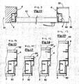
- figures 1 and 2 show two examples of main section 1 and 2 for making the uprights of a frame obtained according to the invention, respectively for at least one push-type closure panel 60, shown in figures 4 and 5 , or for at least one closure with pull-type leaf 61, shown in figures 10 and 11 .
- the above described first face 31 has a thicker portion 32, having a width substantially equal to the thickness of the above described closure wing, consisting of an inner wall 22 and an external wall 23, with interposition of a chamber 24.
- the chamber 24 can be absent, and the thicker portion 32 is solid.
- the main section 1 comprises a main chamber 10 and an adjacent chamber 11
- the main section 2 comprises a chamber 12 having a substantially rectangular cross section to support abutment surface 14.
- Figure 3 shows a complementary extruded section 4 associable to the above described main section 1 and 2 described in figures 1 and 2 , suitable for completing to cover the thickness of said wall at the aperture (for example in figure 5-9 and 11-15 ).
- This complementary section 4 has a reference face 41 adapted to operatively contact one of said side faces 1.5 of said main section 1 or 2, and an outer face 40 adapted to remain visible in the aperture defined by the frame on said wall.
- a complementary wing 45 can be provided, having a shape equal to wing 17 of main sections 1, 2 and 3 of figures 1, 2 .
- the complementary wing 45 extends from said outer face 40 at the opposite ends with respect to said reference face 41.
- an engagement portion 42 is provided adapted to couple with said wing 17 of said main section 1 or 2 or to said complementary wing 45 of another complementary section 4.
- the above described engagement portion 42 is conformed in order to reproduce in negative the shape of the wing 17 of a main section 1 or 2, this engagement portion 42 being adapted to couple to wing 17 of a section 1 or 2 as above described or to a wing 45 of a next complementary section 4 mounted.
- the outer face 40 and the reference face 41 are arranged substantially at an L configuration.
- the above described section 4 can have then a notch 44 in an intermediate position of the above described reference surface 41, adapted to assist cutting an exceeding portion, if required.
- the complementary section 4 of the example of figure 3 comprises a first support portion 47 parallel to the wall 50, shown in figures 4, 5 and 10, 11 , which extends opposite to the outer face 40. From the first support portion 47 wing 45 protrudes at right angles.
- a second support portion 48 can be provided, parallel to said first support portion 47 and distant from said reference face 41 of the same length as the width of the wing 17 of a main section 1 or 2.
- the complementary section 4 has a complementary protrusion 55, equal to the protrusion 49 and the protrusion 18 of the main section opposite to the outer face 40 and at a distance from the second support portion 48 equal to the width of the wing 17 of the main section 1 or 2 or the wing 45 of section 4 same.
- a wing 46 remains, substantially equal to wing 45.
- the inner surface opposite to the outer face 40 is knurled, as also the surface of the above described first and/or second portion of reference is knurled, and oriented outwards with respect to reference face 41.
- Figure 4 shows a cross sectional view of an embodiment of a frame for doors or windows for receiving at least one push-type closure panel 60 having a surface on a same plane of a wall, mounted on a wall 50 having a thickness equal to the total width of a main section 1 and of a complementary section 4 associated.
- the invention can be fixed to a wall brick-wall 51.
- a wall is shown obtained from boards 52, for example of plasterboard, without showing the relative support structure. Instead, on the left side a brick-wall 51 is shown,
- Figures from 5 to 8 show alternative assembling embodiments of a main section 1 for a push-type closure panel 60 ( figure 4 ) associated respectively to a complementary section 4, a partial complementary section 4', a complementary section 4 with a partial complementary section 4', two complementary profiles 4 in series, according to the thickness of the wall.
- figure 9 shows a cross sectional view of an embodiment of a frame for doors or windows for receiving at least one closure panel having a surface on a same plane of a wall for a pull-type door 61, for a board-wall 50 of thickness equal to the width total of a main section 2 and of an associated complementary section 4.
- the invention can be fixed to a brick-wall 51 (shown at the left).
- Figures from 10 to 13 show alternative embodiments of assembling a main section 2 for a closure with pull-type leaf associated respectively to a complementary section 4, a partial complementary section 4', a complementary section 4 with a partial complementary section 4', two complementary profiles 4 in series, depending the thickness of the wall.
- closure panels and walls are not limitative, being various other solutions possible according to the shape and the arrangements of the walls.
- Figure 14 shows an alternative exemplary embodiment of a main section 3, as already shown in figure 16, but with two support wings 17 at opposite sides.
- a section 3 can be used for the frame of a door for access to a recess, for example a built-in wardrobe as shown in figure 27. More in the detail the section 3 has both side faces knurled and wings 17 protrude from such faces.
- the first face 31 from the side of the aperture comprises an enlarged portion 110 with a bevelled portion 111 to assist centring screws for fastening a hinge.
- the inner sides can comprise respective channels 112 for assembling the head of more profiles in turn.
- Figure 15 shows possible assembling configurations of such a section 3 for a board-wall 52.
- Section 3 is mounted with a complementary section 4 in case of a wall of width higher than section 3.
- section 3 can be mounted through a bracket 120.
Landscapes
- Engineering & Computer Science (AREA)
- Architecture (AREA)
- Civil Engineering (AREA)
- Structural Engineering (AREA)
- Physics & Mathematics (AREA)
- Electromagnetism (AREA)
- Securing Of Glass Panes Or The Like (AREA)
- Arrangement Of Elements, Cooling, Sealing, Or The Like Of Lighting Devices (AREA)
- Mirrors, Picture Frames, Photograph Stands, And Related Fastening Devices (AREA)
Claims (6)
- Kombination einer Rahmenstruktur (1, 2, 3, 4, 4'), einer Verschlussplatte (60, 61, 70) und einer Wand (50, 51, 52), wobei die Rahmenstruktur für Türen und Fenster, für Möbel oder Beleuchtungen, zur Aufnahme mindestens einer festen oder beweglichen Verschlussplatte (60, 61, 70) dient, wobei die Struktur (1, 2, 3, 4, 4') in der Wand (50, 51, 52) enthalten ist, die eine Holztrennwand oder eine Ziegelwand ist, wobei die Rahmenstruktur (1, 2, 3, 4, 4') eine öffnung definiert, wo die Verschlussplatte (60, 61, 70) in Eingriff ist, wobei die öffnung der Rahmenstruktur (1, 2, 3, 4, 4') derart ist, dass die Verschlussplatte (60, 61, 70) in der geschlossenen Stellung mindestens eine Seite mit einer Oberfläche in einer selben Ebene wie die Wand (50, 51, 52) aufweist, wobei die Rahmenstruktur (1, 2, 3, 4, 4') dafür ausgelegt ist, die Dicke der Wand bei der öffnung in der Wand modular zu füllen und einen Hauptabschnitt (1, 2, 3) und einen rgänzungsabschnitt (4, 4') umfasst, wobei der Hauptabschnitt eine erste Fläche (31) auf derselben Seite der Öffnung, wobei die erste Fläche (31) auf der Leibungsseite der öffnung sichtbar ist, eine zweite Fläche (30), die der öffnung gegenüberliegt, aufweist, wobei von einer ersten Seitenfläche (16) zwei Seitenflächen (15, 16) und ein erster Stützflügel (17) vorstehen, wobei eine Platte der Holztrennwand oder des Putzes der Ziegelwand mindestens an einer der Seitenflächen (15, 16) und an dem ersten Stützflügel (17) gestützt sind, wobei der Hauptabschnitt (1, 2, 3), der dem Ergänzungsabschnitt (4, 4') zugeordnet ist, für den schluss der Abdeckung der gesamten Dicke der Wand (50, 51, 52) bei der Öffnung in der Weise geeignet ist, dass die Gesamtdicke der Rahmenstruktur (1, 2, 3, 4, 4'), die den Hauptabschnitt (1, 2, 3) und den Ergänzungsabschnitt (4, 4') umfasst, gleich der Dicke der Wand (50, 51, 52) ist, wobei der Ergänzungsabschnitt (4, 4') eine Referenzfläche (41), die funktional parallel zu einer der Seitenflächen (15, 16) des Hauptabschnitts (1, 2, 3) ist, eine Außenfläche (40), die dafür ausgelegt ist, in der Öffnung sichtbar zu bleiben und die auf die erste Fläche (31) des Hauptabschnitts (1, 2, 3) ausgerichtet ist, wobei sie die erste Fläche (31) des Hauptabschnitts (1) auf eine gewünschte Länge verlängert, die erforderlich ist, um die gesamte Dicke der Wand (50, 51, 52) zu bedecken, und einen Eingriffsabschnitt (42) für den kraftschlüssigen Eingriff des Ergänzungsabschnitts (4, 4') mit dem Hauptabschnitt (1, 2, 3) aufweist,
dadurch gekennzeichnet, dass
die zwei Seitenflächen (15, 16) des Hauptabschnitts (1, 2, 3) im Wesentlichen parallel zu der Wand (50, 51, 52) sind, wobei der erste Stützflügel (17) rechtwinklig von der ersten Seitenfläche (16) so vorsteht, dass der Stützflügel orthogonal zu der Wand (50, 51, 52) ist und eine rechtwinklige Kante in Bezug auf die erste Seitenflächen (16) bildet, und so, dass eine Platte der Holztrennwand oder des Putzes der Ziegelwand rechtwinklig zwischen der ersten Seitenfläche (16) und dem ersten Stützflügel (17) gestützt ist, und dass ein zweiter Flügel (17) rechtwinklig von der zweiten Seitenfläche (15) des Hauptabschnitts (1, 2, 3) vorsteht, wobei der zweite Flügel (17) auf die erste Fläche (31) ausgerichtet ist, und wobei der Eingriffsabschnitt (42) des Ergänzungsabschnitts (4, 4') mit dem zweiten Flügel (17) des Hauptabschnitts (1, 2, 3) in der Weise kraftschlüssig in Eingriff ist, dass die Außenfläche (40) des Ergänzungsabschnitts (4, 4') und die erste Fläche (31) des Hauptabschnitts (1, 2, 3) in derselben Ebene ausgerichtet sind. - Kombination nach Anspruch 1, bei der der oder jeder rechtwinklige Flügel (17) eine geriffelte Innenoberfläche aufweist, die dafür ausgelegt ist, den Rahmen an einer Platte einer Holztrennwand oder an dem Putz einer Ziegelwand haftend zu halten.
- Kombination nach Anspruch 1, bei der mindestens eine der zwei Seitenflächen (15, 16) auf der Außenseite geriffelt ist.
- Kombination nach Anspruch 1, bei der der oder jeder rechtwinklige Flügel (17) mit einem Vorsprung (18) endet, der in Übereinstimmung mit einer entgegengesetzten Richtung in Bezug auf die Öffnung orientiert ist, wobei dieser Vorsprung die Funktion aufweist, eine Kante zwischen der Wand (50, 51, 52) und der Öffnung zu bilden.
- Kombination nach Anspruch 1, bei der der Ergänzungsabschnitt (4, 4') einen Ergänzungsflügel (45) umfasst, der in einer Weise an einem der Referenzfläche (41) gegenüberliegenden Ende koplanar in Bezug auf die Außenfläche (40) verläuft, dass der Ergänzungsflügel (45) eine ähnliche Form wie der zu dem Hauptabschnitt (1, 2, 3) rechtwinklige Flügel (17) aufweist.
- Kombination nach Anspruch 1, bei der der Eingriffsabschnitt (42) des Ergänzungsabschnitts (4, 4') so angepasst ist, dass er die Form des zu dem Hauptabschnitt (1, 2, 3) rechtwinkligen Flügels (17) negativ reproduziert, wobei der Eingriffsabschnitt (42) dafür ausgelegt ist, mit dem rechtiuinkligen Flügel (17) kraftschlüssig in Eingriff zu gelangen.
Applications Claiming Priority (2)
| Application Number | Priority Date | Filing Date | Title |
|---|---|---|---|
| ITPI20060015 ITPI20060015A1 (it) | 2006-02-09 | 2006-02-09 | Struttura di telaio per serramenti, arredi o illuminazioni raso muro. |
| PCT/IB2007/000318 WO2007091171A2 (en) | 2006-02-09 | 2007-02-09 | Frame structure for doors or windows, for furniture or for lightings, having a surface on a same plane of a wall |
Publications (2)
| Publication Number | Publication Date |
|---|---|
| EP1945895A2 EP1945895A2 (de) | 2008-07-23 |
| EP1945895B1 true EP1945895B1 (de) | 2012-06-06 |
Family
ID=38162282
Family Applications (1)
| Application Number | Title | Priority Date | Filing Date |
|---|---|---|---|
| EP07705573A Not-in-force EP1945895B1 (de) | 2006-02-09 | 2007-02-09 | Rahmenstruktur für türen oder fenster, für möbel oder beleuchtungen mit einer fläche, die auf gleicher ebene wie die wand ist |
Country Status (4)
| Country | Link |
|---|---|
| EP (1) | EP1945895B1 (de) |
| ES (1) | ES2389264T3 (de) |
| IT (1) | ITPI20060015A1 (de) |
| WO (1) | WO2007091171A2 (de) |
Families Citing this family (11)
| Publication number | Priority date | Publication date | Assignee | Title |
|---|---|---|---|---|
| GB2437731B (en) * | 2006-05-03 | 2011-01-05 | Epwin Group Ltd | Cavity Closer |
| BE1017524A3 (nl) * | 2007-03-23 | 2008-11-04 | Thierry Baert | Deurbeslag. |
| NL1036035C2 (nl) * | 2008-10-08 | 2010-04-09 | Roelof Van Der Toorn | Staander voor het vormen van een afscherming, een afscherming en een werkwijze daarvoor. |
| DE202010003127U1 (de) * | 2009-03-05 | 2010-07-29 | Altura Leiden Holding B.V. | Trennwand |
| US20160281414A1 (en) * | 2012-05-16 | 2016-09-29 | Olmos Scofield, Llc | Window assembly to engage a window to the frame of a window opening of a building |
| ITMO20130090A1 (it) * | 2013-04-09 | 2014-10-10 | Franco Donato | Kit di elementi per serramenti |
| EP2999839A1 (de) * | 2013-05-23 | 2016-03-30 | Rinvisible Bvba | Unsichtbare fensterrahmen |
| PL407143A1 (pl) * | 2014-02-11 | 2015-08-17 | Jackiewicz Wiesław Entra | Zintegrowana ościeżnica drzwiowa |
| ITUB20160910A1 (it) * | 2016-02-19 | 2017-08-19 | Alluminia S R L | Porta filo-muro con telaio comprendente un profilato perfezionato. |
| PL236861B1 (pl) | 2016-07-19 | 2021-02-22 | Fakro Pp Spolka Z Ograniczona Odpowiedzialnoscia | Schody strychowe z wypełnieniem licującym |
| IT201700082393A1 (it) * | 2017-07-21 | 2019-01-21 | De Faveri Srl | Telaio per elementi di chiusura a scomparsa per l'occultamento di piccoli vani tecnici nelle costruzioni. |
Family Cites Families (11)
| Publication number | Priority date | Publication date | Assignee | Title |
|---|---|---|---|---|
| AT388019B (de) | 1987-09-21 | 1989-04-25 | Waldner Fa Felix | Verglasungsprofil fuer tueren, fenster od.dgl. |
| GB2295185B (en) * | 1994-11-16 | 1999-04-21 | Abbott Joinery Ltd | Frame elements |
| IT238223Y1 (it) | 1997-06-19 | 2000-10-16 | Porta Arredo S N C Di Vaccari | Struttura modulare preassemblabile di stipiti per porte senza mostra a filo parete con battente a spingere |
| SG87079A1 (en) * | 1999-02-19 | 2002-03-19 | Joinwide Invest Ltd | Method of partitioning office spaces |
| GB2365476A (en) * | 2000-05-27 | 2002-02-20 | R A Whiting Design Ltd | Frame arrangement allowing a second frame to be inserted in two opposite directions |
| ITVI20010007U1 (it) | 2001-02-20 | 2002-08-21 | Porta Arredo Srl | Telaio per porte o sportelli con cerniera a vista senza mostra a filoparete con battente a tirare |
| JP3879488B2 (ja) | 2001-11-09 | 2007-02-14 | アイカ工業株式会社 | ブースにおける化粧パネルの接続構造 |
| ITVI20030064A1 (it) | 2003-03-26 | 2004-09-27 | Ruggero Grandi | Struttura di telaio per pareti divisorie di vani di edifici0. |
| JP4188745B2 (ja) | 2003-04-15 | 2008-11-26 | 株式会社岡村製作所 | 間仕切パネルの建付け構造 |
| JP2005264667A (ja) | 2004-03-22 | 2005-09-29 | Misawa Homes Co Ltd | 化粧枠の取付構造 |
| DE202004017808U1 (de) | 2004-11-17 | 2005-01-13 | Rheinhold & Mahla Ag | Verbindungsprofil |
-
2006
- 2006-02-09 IT ITPI20060015 patent/ITPI20060015A1/it unknown
-
2007
- 2007-02-09 WO PCT/IB2007/000318 patent/WO2007091171A2/en not_active Ceased
- 2007-02-09 EP EP07705573A patent/EP1945895B1/de not_active Not-in-force
- 2007-02-09 ES ES07705573T patent/ES2389264T3/es active Active
Also Published As
| Publication number | Publication date |
|---|---|
| EP1945895A2 (de) | 2008-07-23 |
| ES2389264T3 (es) | 2012-10-24 |
| WO2007091171A3 (en) | 2007-10-18 |
| ITPI20060015A1 (it) | 2007-08-10 |
| WO2007091171A2 (en) | 2007-08-16 |
Similar Documents
| Publication | Publication Date | Title |
|---|---|---|
| EP1945895B1 (de) | Rahmenstruktur für türen oder fenster, für möbel oder beleuchtungen mit einer fläche, die auf gleicher ebene wie die wand ist | |
| EP1081325A2 (de) | Einheitsprofil zur Fensterkonstruktion | |
| EP2315900B1 (de) | Flügel für schiebetüren oder -fenster | |
| US9091119B2 (en) | Windows and doors assembly structure having a joint portion of 45 degrees | |
| CN213980451U (zh) | 模块化玻璃门 | |
| KR101947224B1 (ko) | 복합 소재 창호 | |
| US11808079B2 (en) | Inner frame for door or window, skylight comprising the same and manufacturing method thereof | |
| US11655668B2 (en) | Seamless multi-panel door | |
| US11619090B1 (en) | Composite fenestration assembly | |
| CA2192420A1 (en) | Extruded carpentry framing | |
| US20090223149A1 (en) | Mitered shutter | |
| US11905756B2 (en) | Polymeric wind and debris resistant garage door window frame and method of manufacture | |
| US20170226753A1 (en) | Slidable snap-in trim system | |
| JP3378985B2 (ja) | 建 具 | |
| CA3207091A1 (en) | Modular barrier panel frame reinforcement systems and methods | |
| EP3748116B1 (de) | Tür oder fenster | |
| JPH11303509A (ja) | 断熱サッシ | |
| KR200355668Y1 (ko) | 발코니창 | |
| KR102018426B1 (ko) | 재단 및 조립이 용이한 입면 분할 창호 | |
| GB2248648A (en) | Sliding door and window frame joints and packing elements for such joints | |
| KR102886644B1 (ko) | 특수도어용 헤더 결합구조 | |
| GB2345512A (en) | Doors and door assemblies | |
| CN222207622U (zh) | 一种可变中梃 | |
| JP2520697Y2 (ja) | サッシ用枠材 | |
| JPH0312144Y2 (de) |
Legal Events
| Date | Code | Title | Description |
|---|---|---|---|
| PUAI | Public reference made under article 153(3) epc to a published international application that has entered the european phase |
Free format text: ORIGINAL CODE: 0009012 |
|
| 17P | Request for examination filed |
Effective date: 20080306 |
|
| AK | Designated contracting states |
Kind code of ref document: A2 Designated state(s): AT BE BG CH CY CZ DE DK EE ES FI FR GB GR HU IE IS IT LI LT LU LV MC NL PL PT RO SE SI SK TR |
|
| 17Q | First examination report despatched |
Effective date: 20081215 |
|
| TPAC | Observations by third parties |
Free format text: ORIGINAL CODE: EPIDOSNTIPA |
|
| RAP1 | Party data changed (applicant data changed or rights of an application transferred) |
Owner name: PUCCI SAORO, S.R.L. |
|
| GRAP | Despatch of communication of intention to grant a patent |
Free format text: ORIGINAL CODE: EPIDOSNIGR1 |
|
| DAX | Request for extension of the european patent (deleted) | ||
| GRAS | Grant fee paid |
Free format text: ORIGINAL CODE: EPIDOSNIGR3 |
|
| GRAA | (expected) grant |
Free format text: ORIGINAL CODE: 0009210 |
|
| AK | Designated contracting states |
Kind code of ref document: B1 Designated state(s): AT BE BG CH CY CZ DE DK EE ES FI FR GB GR HU IE IS IT LI LT LU LV MC NL PL PT RO SE SI SK TR |
|
| REG | Reference to a national code |
Ref country code: GB Ref legal event code: FG4D |
|
| REG | Reference to a national code |
Ref country code: CH Ref legal event code: NV Representative=s name: STUMP UND PARTNER PATENTANWAELTE AG Ref country code: CH Ref legal event code: EP Ref country code: AT Ref legal event code: REF Ref document number: 561143 Country of ref document: AT Kind code of ref document: T Effective date: 20120615 |
|
| REG | Reference to a national code |
Ref country code: IE Ref legal event code: FG4D |
|
| REG | Reference to a national code |
Ref country code: DE Ref legal event code: R096 Ref document number: 602007023148 Country of ref document: DE Effective date: 20120809 |
|
| REG | Reference to a national code |
Ref country code: NL Ref legal event code: VDEP Effective date: 20120606 |
|
| REG | Reference to a national code |
Ref country code: ES Ref legal event code: FG2A Ref document number: 2389264 Country of ref document: ES Kind code of ref document: T3 Effective date: 20121024 |
|
| PG25 | Lapsed in a contracting state [announced via postgrant information from national office to epo] |
Ref country code: SE Free format text: LAPSE BECAUSE OF FAILURE TO SUBMIT A TRANSLATION OF THE DESCRIPTION OR TO PAY THE FEE WITHIN THE PRESCRIBED TIME-LIMIT Effective date: 20120606 Ref country code: LT Free format text: LAPSE BECAUSE OF FAILURE TO SUBMIT A TRANSLATION OF THE DESCRIPTION OR TO PAY THE FEE WITHIN THE PRESCRIBED TIME-LIMIT Effective date: 20120606 Ref country code: CY Free format text: LAPSE BECAUSE OF FAILURE TO SUBMIT A TRANSLATION OF THE DESCRIPTION OR TO PAY THE FEE WITHIN THE PRESCRIBED TIME-LIMIT Effective date: 20120606 Ref country code: FI Free format text: LAPSE BECAUSE OF FAILURE TO SUBMIT A TRANSLATION OF THE DESCRIPTION OR TO PAY THE FEE WITHIN THE PRESCRIBED TIME-LIMIT Effective date: 20120606 |
|
| REG | Reference to a national code |
Ref country code: LT Ref legal event code: MG4D Effective date: 20120606 |
|
| PG25 | Lapsed in a contracting state [announced via postgrant information from national office to epo] |
Ref country code: GR Free format text: LAPSE BECAUSE OF FAILURE TO SUBMIT A TRANSLATION OF THE DESCRIPTION OR TO PAY THE FEE WITHIN THE PRESCRIBED TIME-LIMIT Effective date: 20120907 Ref country code: LV Free format text: LAPSE BECAUSE OF FAILURE TO SUBMIT A TRANSLATION OF THE DESCRIPTION OR TO PAY THE FEE WITHIN THE PRESCRIBED TIME-LIMIT Effective date: 20120606 Ref country code: SI Free format text: LAPSE BECAUSE OF FAILURE TO SUBMIT A TRANSLATION OF THE DESCRIPTION OR TO PAY THE FEE WITHIN THE PRESCRIBED TIME-LIMIT Effective date: 20120606 |
|
| PG25 | Lapsed in a contracting state [announced via postgrant information from national office to epo] |
Ref country code: BE Free format text: LAPSE BECAUSE OF FAILURE TO SUBMIT A TRANSLATION OF THE DESCRIPTION OR TO PAY THE FEE WITHIN THE PRESCRIBED TIME-LIMIT Effective date: 20120606 Ref country code: EE Free format text: LAPSE BECAUSE OF FAILURE TO SUBMIT A TRANSLATION OF THE DESCRIPTION OR TO PAY THE FEE WITHIN THE PRESCRIBED TIME-LIMIT Effective date: 20120606 Ref country code: NL Free format text: LAPSE BECAUSE OF FAILURE TO SUBMIT A TRANSLATION OF THE DESCRIPTION OR TO PAY THE FEE WITHIN THE PRESCRIBED TIME-LIMIT Effective date: 20120606 Ref country code: CZ Free format text: LAPSE BECAUSE OF FAILURE TO SUBMIT A TRANSLATION OF THE DESCRIPTION OR TO PAY THE FEE WITHIN THE PRESCRIBED TIME-LIMIT Effective date: 20120606 Ref country code: IS Free format text: LAPSE BECAUSE OF FAILURE TO SUBMIT A TRANSLATION OF THE DESCRIPTION OR TO PAY THE FEE WITHIN THE PRESCRIBED TIME-LIMIT Effective date: 20121006 Ref country code: SK Free format text: LAPSE BECAUSE OF FAILURE TO SUBMIT A TRANSLATION OF THE DESCRIPTION OR TO PAY THE FEE WITHIN THE PRESCRIBED TIME-LIMIT Effective date: 20120606 Ref country code: RO Free format text: LAPSE BECAUSE OF FAILURE TO SUBMIT A TRANSLATION OF THE DESCRIPTION OR TO PAY THE FEE WITHIN THE PRESCRIBED TIME-LIMIT Effective date: 20120606 |
|
| PG25 | Lapsed in a contracting state [announced via postgrant information from national office to epo] |
Ref country code: PT Free format text: LAPSE BECAUSE OF FAILURE TO SUBMIT A TRANSLATION OF THE DESCRIPTION OR TO PAY THE FEE WITHIN THE PRESCRIBED TIME-LIMIT Effective date: 20121008 Ref country code: PL Free format text: LAPSE BECAUSE OF FAILURE TO SUBMIT A TRANSLATION OF THE DESCRIPTION OR TO PAY THE FEE WITHIN THE PRESCRIBED TIME-LIMIT Effective date: 20120606 |
|
| PLBE | No opposition filed within time limit |
Free format text: ORIGINAL CODE: 0009261 |
|
| STAA | Information on the status of an ep patent application or granted ep patent |
Free format text: STATUS: NO OPPOSITION FILED WITHIN TIME LIMIT |
|
| PG25 | Lapsed in a contracting state [announced via postgrant information from national office to epo] |
Ref country code: DK Free format text: LAPSE BECAUSE OF FAILURE TO SUBMIT A TRANSLATION OF THE DESCRIPTION OR TO PAY THE FEE WITHIN THE PRESCRIBED TIME-LIMIT Effective date: 20120606 |
|
| 26N | No opposition filed |
Effective date: 20130307 |
|
| REG | Reference to a national code |
Ref country code: DE Ref legal event code: R097 Ref document number: 602007023148 Country of ref document: DE Effective date: 20130307 |
|
| PG25 | Lapsed in a contracting state [announced via postgrant information from national office to epo] |
Ref country code: BG Free format text: LAPSE BECAUSE OF FAILURE TO SUBMIT A TRANSLATION OF THE DESCRIPTION OR TO PAY THE FEE WITHIN THE PRESCRIBED TIME-LIMIT Effective date: 20120906 |
|
| PG25 | Lapsed in a contracting state [announced via postgrant information from national office to epo] |
Ref country code: MC Free format text: LAPSE BECAUSE OF NON-PAYMENT OF DUE FEES Effective date: 20130228 |
|
| REG | Reference to a national code |
Ref country code: IE Ref legal event code: MM4A |
|
| REG | Reference to a national code |
Ref country code: CH Ref legal event code: PCAR Free format text: NEW ADDRESS: ZIMMERGASSE 16, 8008 ZUERICH (CH) |
|
| PG25 | Lapsed in a contracting state [announced via postgrant information from national office to epo] |
Ref country code: IE Free format text: LAPSE BECAUSE OF NON-PAYMENT OF DUE FEES Effective date: 20130209 |
|
| PG25 | Lapsed in a contracting state [announced via postgrant information from national office to epo] |
Ref country code: TR Free format text: LAPSE BECAUSE OF FAILURE TO SUBMIT A TRANSLATION OF THE DESCRIPTION OR TO PAY THE FEE WITHIN THE PRESCRIBED TIME-LIMIT Effective date: 20120606 |
|
| PG25 | Lapsed in a contracting state [announced via postgrant information from national office to epo] |
Ref country code: HU Free format text: LAPSE BECAUSE OF FAILURE TO SUBMIT A TRANSLATION OF THE DESCRIPTION OR TO PAY THE FEE WITHIN THE PRESCRIBED TIME-LIMIT; INVALID AB INITIO Effective date: 20070209 Ref country code: LU Free format text: LAPSE BECAUSE OF NON-PAYMENT OF DUE FEES Effective date: 20130209 |
|
| REG | Reference to a national code |
Ref country code: FR Ref legal event code: PLFP Year of fee payment: 10 |
|
| REG | Reference to a national code |
Ref country code: FR Ref legal event code: PLFP Year of fee payment: 11 |
|
| REG | Reference to a national code |
Ref country code: FR Ref legal event code: PLFP Year of fee payment: 12 |
|
| PGFP | Annual fee paid to national office [announced via postgrant information from national office to epo] |
Ref country code: CH Payment date: 20180301 Year of fee payment: 12 Ref country code: DE Payment date: 20180227 Year of fee payment: 12 Ref country code: GB Payment date: 20180323 Year of fee payment: 12 Ref country code: ES Payment date: 20180301 Year of fee payment: 12 |
|
| PGFP | Annual fee paid to national office [announced via postgrant information from national office to epo] |
Ref country code: FR Payment date: 20180221 Year of fee payment: 12 Ref country code: AT Payment date: 20180227 Year of fee payment: 12 Ref country code: IT Payment date: 20180221 Year of fee payment: 12 |
|
| REG | Reference to a national code |
Ref country code: DE Ref legal event code: R119 Ref document number: 602007023148 Country of ref document: DE |
|
| REG | Reference to a national code |
Ref country code: CH Ref legal event code: PL |
|
| REG | Reference to a national code |
Ref country code: AT Ref legal event code: MM01 Ref document number: 561143 Country of ref document: AT Kind code of ref document: T Effective date: 20190209 |
|
| GBPC | Gb: european patent ceased through non-payment of renewal fee |
Effective date: 20190209 |
|
| PG25 | Lapsed in a contracting state [announced via postgrant information from national office to epo] |
Ref country code: AT Free format text: LAPSE BECAUSE OF NON-PAYMENT OF DUE FEES Effective date: 20190209 Ref country code: CH Free format text: LAPSE BECAUSE OF NON-PAYMENT OF DUE FEES Effective date: 20190228 Ref country code: LI Free format text: LAPSE BECAUSE OF NON-PAYMENT OF DUE FEES Effective date: 20190228 |
|
| PG25 | Lapsed in a contracting state [announced via postgrant information from national office to epo] |
Ref country code: GB Free format text: LAPSE BECAUSE OF NON-PAYMENT OF DUE FEES Effective date: 20190209 Ref country code: DE Free format text: LAPSE BECAUSE OF NON-PAYMENT OF DUE FEES Effective date: 20190903 |
|
| PG25 | Lapsed in a contracting state [announced via postgrant information from national office to epo] |
Ref country code: FR Free format text: LAPSE BECAUSE OF NON-PAYMENT OF DUE FEES Effective date: 20190228 Ref country code: IT Free format text: LAPSE BECAUSE OF NON-PAYMENT OF DUE FEES Effective date: 20190209 |
|
| REG | Reference to a national code |
Ref country code: ES Ref legal event code: FD2A Effective date: 20200327 |
|
| PG25 | Lapsed in a contracting state [announced via postgrant information from national office to epo] |
Ref country code: ES Free format text: LAPSE BECAUSE OF NON-PAYMENT OF DUE FEES Effective date: 20190210 |