EP1945846B1 - Machine for continuous treatment of a fabric in rope form and relative method - Google Patents
Machine for continuous treatment of a fabric in rope form and relative method Download PDFInfo
- Publication number
- EP1945846B1 EP1945846B1 EP06821770A EP06821770A EP1945846B1 EP 1945846 B1 EP1945846 B1 EP 1945846B1 EP 06821770 A EP06821770 A EP 06821770A EP 06821770 A EP06821770 A EP 06821770A EP 1945846 B1 EP1945846 B1 EP 1945846B1
- Authority
- EP
- European Patent Office
- Prior art keywords
- fabric
- section
- machine
- transfer
- treatment
- Prior art date
- Legal status (The legal status is an assumption and is not a legal conclusion. Google has not performed a legal analysis and makes no representation as to the accuracy of the status listed.)
- Active
Links
- 239000004744 fabric Substances 0.000 title claims abstract description 187
- 238000011282 treatment Methods 0.000 title claims description 121
- 238000000034 method Methods 0.000 title claims description 26
- 238000012546 transfer Methods 0.000 claims abstract description 88
- 238000009825 accumulation Methods 0.000 claims abstract description 70
- 239000012530 fluid Substances 0.000 claims description 15
- 230000002457 bidirectional effect Effects 0.000 claims description 14
- 230000007423 decrease Effects 0.000 claims description 12
- 238000012545 processing Methods 0.000 claims description 9
- 238000005086 pumping Methods 0.000 claims description 6
- 230000003247 decreasing effect Effects 0.000 claims description 3
- 230000002441 reversible effect Effects 0.000 claims description 3
- 238000012937 correction Methods 0.000 claims 1
- 238000012986 modification Methods 0.000 claims 1
- 230000004048 modification Effects 0.000 claims 1
- 238000001035 drying Methods 0.000 description 13
- 239000000126 substance Substances 0.000 description 11
- 102000004190 Enzymes Human genes 0.000 description 9
- 108090000790 Enzymes Proteins 0.000 description 9
- 230000000694 effects Effects 0.000 description 9
- 238000005406 washing Methods 0.000 description 9
- 238000004519 manufacturing process Methods 0.000 description 8
- 238000010025 steaming Methods 0.000 description 5
- 230000000670 limiting effect Effects 0.000 description 4
- 239000007921 spray Substances 0.000 description 4
- 230000001360 synchronised effect Effects 0.000 description 4
- 238000010586 diagram Methods 0.000 description 3
- 238000004043 dyeing Methods 0.000 description 3
- 238000005265 energy consumption Methods 0.000 description 2
- 238000005470 impregnation Methods 0.000 description 2
- 239000002184 metal Substances 0.000 description 2
- XLYOFNOQVPJJNP-UHFFFAOYSA-N water Substances O XLYOFNOQVPJJNP-UHFFFAOYSA-N 0.000 description 2
- 230000001133 acceleration Effects 0.000 description 1
- 238000006243 chemical reaction Methods 0.000 description 1
- 238000010276 construction Methods 0.000 description 1
- 230000001419 dependent effect Effects 0.000 description 1
- 238000011161 development Methods 0.000 description 1
- 230000018109 developmental process Effects 0.000 description 1
- 238000005516 engineering process Methods 0.000 description 1
- 238000005304 joining Methods 0.000 description 1
- 238000012423 maintenance Methods 0.000 description 1
- 238000007726 management method Methods 0.000 description 1
- 238000005457 optimization Methods 0.000 description 1
- 230000036961 partial effect Effects 0.000 description 1
- 230000002829 reductive effect Effects 0.000 description 1
- 230000008929 regeneration Effects 0.000 description 1
- 238000011069 regeneration method Methods 0.000 description 1
- 238000003860 storage Methods 0.000 description 1
Images


Classifications
-
- D—TEXTILES; PAPER
- D06—TREATMENT OF TEXTILES OR THE LIKE; LAUNDERING; FLEXIBLE MATERIALS NOT OTHERWISE PROVIDED FOR
- D06C—FINISHING, DRESSING, TENTERING OR STRETCHING TEXTILE FABRICS
- D06C19/00—Breaking or softening of fabrics
-
- D—TEXTILES; PAPER
- D06—TREATMENT OF TEXTILES OR THE LIKE; LAUNDERING; FLEXIBLE MATERIALS NOT OTHERWISE PROVIDED FOR
- D06B—TREATING TEXTILE MATERIALS USING LIQUIDS, GASES OR VAPOURS
- D06B3/00—Passing of textile materials through liquids, gases or vapours to effect treatment, e.g. washing, dyeing, bleaching, sizing, impregnating
- D06B3/28—Passing of textile materials through liquids, gases or vapours to effect treatment, e.g. washing, dyeing, bleaching, sizing, impregnating of fabrics propelled by, or with the aid of, jets of the treating material
Definitions
- the present invention relates to a machine for treating a fabric. More specifically, the present invention relates to a continuous cycle machine for treating a fabric in rope form. Moreover, the invention relates to a respective method for continuous treatment of fabric in rope form.
- machines that subject the pieces of fabric to treatments both in a bath and without a bath by transferring the fabric along a transfer path where said fabric is subjected to the mechanical action of one or more mechanical members and, if necessary, a chemical action by means of enzymes and/or a thermal action.
- machines are known that process fabrics in rope form with a discontinuous cycle.
- a rope of fabric of finite length is inserted in the machine and closed joining the head and tail of said rope to each other to form a sort of loop.
- This loop of fabric is made to circulate for a suitable number of times, i.e. for a suitable treatment time, along the treatment path.
- the machine is stopped, depressurized if required, opened and the treated fabric is removed there from to be replaced with a new fabric to be treated.
- Machines of this type see for example patents EP-B-0518065 , EP-B-0565884 , EP-B-0633340 and EP-B-0952247 , in general allow dry fabric to be treated principally in a bath, and have the drawback of requiring frequent stops for loading and unloading, stitching the fabric in a loop and unstitching it. This results in loss of production and high labor costs. The need to depressurize and cool the machine (when it operates at pressure and/or temperature) also results in considerable energy consumption.
- the fabric In multi-tank machines that process the fabric in open width in a continuous cycle, the fabric is fed into a first tank, transferred to the intermediate treatment tanks and then removed gradually from a last tank at the opposite end of the path.
- a supply of fabric In each intermediate tank inside the machine a supply of fabric forms, moving at a greater speed than the speed at which it is inserted into and removed from the machine, so that each section of fabric is subjected to more than one treatment.
- Patent IT-B-1151983 describes a multi-tank machine for continuous treatment of fabric in rope form with tanks placed side by side longitudinally, which comprises a single reel for feeding the fabric from one tank to the other.
- the treatment is bland and the treatment speed limited.
- EP-A-1301658 describes a multi-tank machine for continuous treatment of fabric in rope form with tanks placed side by side that facilitates feed of the fabric from one tank to the next thanks to pneumatic transfer ducts sloping in relation to said tanks, i.e. positioned so that a tank adjacent to the inlet tank of each transfer duct corresponds to the outlet of the same duct.
- An object of the invention is to provide a machine for continuous treatment of fabrics in rope form which is less expensive and simpler to construct, which facilitates control of the treatment process obtaining particularly high production levels and overcoming or reducing at least some of the aforesaid drawbacks of existing machines.
- Another object is to obtain a machine which is more versatile than prior art machines.
- a further object of the present invention is to produce a method that allows continuous processing of a fabric in rope form in an improved and faster way at a moderate cost.
- a machine for continuous treatment of a fabric in rope form comprising: a plurality of treatment sections arranged in series along the feed path of the fabric, each of which has at least two accumulation areas; in each section at least one bidirectional transfer system to transfer the fabric alternatively between accumulation areas of a same section; and means to convey the fabric from one section to an adjacent section, said conveying means being separate from the transfer systems provided in each section.
- the treatment sections are placed side by side longitudinally, i.e. positioned beside each other in the direction of their length so that the accumulation areas of each section are adjacent to the accumulation areas of a same contiguous section.
- the sections extend longitudinally and the accumulation areas are aligned according to this linear extension. Adjacent sections are placed side by side transverse to their longitudinal extension.
- the overall length of the machine is reduced.
- Several sections can also be arranged according to a mixed arrangement, producing customized configurations mainly on the basis of the available space.
- the means to convey the fabric from one section to the other are motorized and their purpose is to lift a supply of fabric stored in an accumulation area and unload it in an accumulation area of an adjacent section to control the supply of fabric in each accumulation area in a substantially independent way, as will be explained in greater detail hereunder.
- the purpose of the bidirectional transfer system is to convey the fabric alternatively in opposite directions from one accumulation area to the other of a same section at a greater speed than the speed at which the fabric is inserted into and removed from the machine and therefore than the speed at which the fabric is transferred from one section to the consecutive one by said transfer means, to allow repeated treatment in each single accumulation area.
- This transfer system is preferably and advantageously produced with a Venturi tube pneumatic system and the path is at least partially pressurized so that, in a simple and inexpensive way, the movement of the fabric in rope form from one accumulation area to the other qan be reversed and further elements for physical treatment of said fabric can be provided.
- At least one striking element in front of the transfer system, in particular at the end of the path in the direction of transfer of the fabric, at least one striking element, preferably a grid, can advantageously be provided.
- two opposed striking elements are provided for each treatment section, as deascribed for example in WO-A-03023111 , in front of the two ends of the pneumatic transfer duct, against which the fabric is made to strike due to the kinetic energy imparted thereto by the transfer system, to increase the effect of the physical treatment and softening of said fabric.
- a grid structure must be understood as any structure suitable to form a striking surface for the fabric and at the same time allowing air to pass through. It can be composed of a series of horizontal and/or vertical bars, a perforate metal sheet, a continuous metal sheet with a central slit or a series of slits varyingly arranged, or other systems.
- a respective suction mouth of a pneumatic circuit can advantageously be provided, to alternatively suck the air emerging from the transfer system.
- the treatment efficiency of the machine is increased.
- the flow of air sucked in by the suction mouths allows an increased acceleration of the fabric, in particular each time the direction of movement is reversed, and therefore higher speeds can be reached to obtain more efficient treatment.
- high temperature air can be used, especially when the machine operates in the drying configuration, providing an air recirculation or regeneration circuit capable of improving the efficiency and increasing the output of the drying system.
- a control unit and sensor means such as load cells or similar systems are provided in each accumulation area, to individually control the supply of fabric stored in the respective accumulation areas, to control the system to reverse the direction of movement of the fabric in each operating or treatment section of the machine (in particular, for example, in the Venturi tube pneumatic system), and to control the means that convey the fabric in rope form from one section to the other, as will be described in greater detail hereunder.
- the present invention relates to a method for continuous treatment of a fabric in rope form comprising the following steps:
- the speed at which the fabric moves between accumulation areas of a same section and reversal of movement imparted by the transfer system of each section can be adjusted separately to the speed at which the fabric is moved from one section to the consecutive section by said conveying means.
- the fabric can be moved several times at high speed between one accumulation area of a same treatment area and the other and vice versa, before being transferred to the subsequent section, while the transfer speed from one section to the subsequent one is substantially lower than the feed speed inside the single treatment section.
- each portion of fabric is treated several times in each treatment section and passage of the fabric from one section to the next is implemented in a way that can be controlled separately from the treatment speed in the single sections.
- the bidirectional transfer system allows physical treatment of the fabric in rope form and transfer is advantageously performed using a pneumatic pressurized-air system.
- the step (c) to alternately transfer the fabric inside each section and the step (d) to convey the fabric from one section to the adjacent one are controlled to produce accumulation areas substantially independent from one another.
- the step (c) and the step (d) are essentially independent from each other, in the sense that each treatment section comprises a bidirectional transfer system independent from the others, allowing separate and even different treatment processes to be implemented in each accumulation area.
- step (c) the direction of movement of the fabric between one accumulation area and the other of a same section is reversed to avoid exhausting the supply of fabric in each accumulation area using suitable control systems, for example by performing this reversal as soon as the weight of a supply of fabric reaches a pre-set lower threshold value.
- motorized conveying means such as reels or pulleys are provided synchronized with fabric entry to and delivery from the machine, so that the quantity of fabric entering the machine is the same as the quantity deliverer moreover, the conveying means are synchronized with each other on the basis of the treatment time required in each of the sections.
- the fabric being treated can undergo a "shrinking" effect - i.e. a decrease in length - in particular as a function of the treatment it undergoes.
- This "shrinking" effect determines a decrease in the reversal time in the accumulation areas, thus making synchronization of the conveying means with entry to and delivery from the machine ineffective and running the risk of exhausting the supplies of fabric or subjecting the fabric to excessive traction.
- the fabric can be delivered continuously from the last tank of the machine at a perfectly synchronized speed, the same as - or preferably lower than, due to the shrinking effect - the speed at which it enters the machine.
- a bath containing suitable enzymes or other chemical products can advantageously be provided inside the accumulation area, so that a machine according to the invention can treat the fabric dry or also in a bath.
- this type of machine can advantageously be utilized for a plurality of dry treatments on a fabric in rope form, such as drying, steaming, softening, shrinkage of the woven or knitted fabric, or for treatment in a bath, such as chemical or physical/chemical and/or enzyme treatments in specific baths and other treatments.
- the machine can also be utilized to perform specific pre-dye washes or washes and treatments with final finishing products for stiff fabrics to be softened and to shrink the weave.
- Chemical or enzyme treatment in a sheet of water at high temperature can also be performed; this consists essentially of producing a sheet of water that evaporates in each accumulation section to maintain an ideal temperature for the specific treatment, e.g. treatment with preimpregnation.
- the same type of treatment can be implemented in all the accumulation areas and in all the treatment sections in order to increase the speed and output of said treatment.
- different treatments can be performed in one or more sections, to produce combined treatments, e.g. to perform in succession washing, treatment in a bath, drying and steaming or to perform in succession washing and treatment in a bath only, or yet again drying and dry steaming only.
- Dry processes such as finishing or processes having an effect on the fabric are improved compared to those performed with a discontinuous machine, with a very advantageous ratio production rate/machine cost.
- the machine according to the invention can advantageously be designed as a complete line and operated automatically for entry and delivery of fabric in rope form. It would also be possible for the fabric to enter and/or be delivered from the machine in open width, although the treatment inside the machine is always performed on fabric in rope form.
- the machine according to the present invention is extremely versatile, as it is particularly suitable to perform one or more processes - dry and/or in a bath - continuously, without any downtimes for loading/unloading, stitching and unstitching the piece, decreasing energy consumption and increasing productivity with smaller overall dimensions compared to conventional machines.
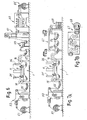
- a machine according to the invention comprises a path formed by a plurality of treatment sections or modules placed side by side along a direction orthogonal to the longitudinal extension of each section, for continuous treatment of a fabric in rope form, one of these treatment sections being indicated in Figure 1 with the reference numeral 2.
- section 2 includes: accumulation areas 3A and 3B, between which a transfer system 7 is arranged; an electronic control unit 18; conveying means of the pulley or reel type 12 to transfer the rope of fabric from one section to the adjacent section, not shown for simplicity in Figure 1 ; and load cells 4A and 4B in the respective accumulation areas 3A and 3B to control the quantity of rope, i.e. the supply of fabric in each accumulation area.
- the accumulation areas 3A and 3B are of the tank type with respective surfaces 5A and 5B which are inclined towards the transfer system 7; it is nonetheless understood that the accumulation areas 3A and 3B are in no way limited to the number and type described, which represent a exemplificative embodiment of the invention.
- the transfer system 7 is of the pneumatic type and comprises: a bidirectional transfer duct 9 of the Venturi tube type, inside which the rope of fabric T is pulled; a pressurized air feed duct 11, to feed the transfer duct 9; and striking elements in the form of grids 10A and 10B placed in front of the outlets of the duct 9.
- This transfer system is also in no way limiting the invention, and represents a exemplificative embodiment thereof.
- the transfer duct 9 can be a duct with a circular or rectangular cross section or similar; moreover, it can have variable geometry to improve the efficiency and increase the output of the transfer system 7.
- Figures 2A and 2B show in particular a partial section of an example of the transfer duct 9 of the type with substantially rectangular variable geometry which comprises movable wall elements P1 and P2 in a first configuration ( Figure 2A ), in which the walls P1 and P2 are moved towards each other to form a section S1 of passage for the rope of fabric; and in a second configuration ( Figure 2B ) in which the wall elements P1 and P2 are moved away from each other to form a larger section of passage S2 than the section S1.
- FIGS. 2A and 2B schematically show a baffle element 8 in the pressurized air feed duct 11, the purpose of which is to select the direction of transfer of the fabric inside the duct 9 by means of control unit 18.
- a fabric in rope form T is fed to the accumulation area 3A of the treatment section 2 by means of a pulley 12 from an adjacent section - not show for simplicity in the figure - to feed a first supply of fabric, then passes through the duct 9 of the transfer system 7, where it is struck against the grid 10B by the pressurized air coming from the feed duct 11 and thus feeds a supply of fabric into the accumulation area 3B.
- Movement of the fabric T between the accumulation areas 3A and 3B is completely reversible.
- washing or dyeing spray nozzles can be provided in the transfer duct 9 to increase the output of any washing and/or dyeing operations on the rope of fabric.
- Figure 3 shows a schematic embodiment of a treatment path produced with three treatment sections 2A to 2C analogous to the section 2 described in Figure 1 ; it is clear that the number of sections can vary without being limited to the number illustrated in the figure.
- the three sections 2A to 2C are placed side by side in a direction transverse to their longitudinal extension and each one comprises motorized pulleys or reels 12, suitable to lift the rope of fabric from an accumulation area 3B or 3C and deposit it in the accumulation area 3D or 3E of the respective adjacent section 2B or 2C.
- Figure 3 shows a roller or reel feeder 14, width which the fabric T is fed to the entrance of the machine 1, and a roller or reel extractor 16 in the last section 2C at the exit of the machine to finally remove the treated fabric therefrom.
- Operation of the machine 1 comprises a first loading step in which the rope of fabric T is positioned along the entire path inside the machine, i.e. the fabric T is-passed from the feeder 14 at the entrance to the extractor 16 at the exit, taking care to arrange it inside each transfer duct 9 and to form a pre-established quantity of supply in each accumulation area 3A to 3F (advantageously approximately 10 to 20 meters, but also up to and over 70 meters in each accumulation area) as a function mainly of the type of fabric and the treatment to be performed.
- the transfer systems 7 present in each section 2A to 2C are activated to violently transfer the fabric T alternately from an accumulation area 3A, 30 or 3E to the respective area 3B, 3D or 3F of the same section 2A, 2B or 2C and vice versa.
- the duration of each transfer before reversal can be set manually by an operator by adjusting the speed of the pressurized air and the minimum quantify of fabric supply, detectable by the load cells 4A or 4B in each accumulation area 3A or 3F.
- control unit 18 can receive data from the load cells 4A and 4B of each accumulation section and control reversal of each transfer system 7 by movement of the baffles 8, see also Figures 2A and 2B , on the basis of the parameters set by the operator, diverting the flow of pressurized air from the feed ducts 11 alternatively in the two directions.
- the transfer speed between consecutive reversals - i.e. the speed of the pressurized air that can be set by the operator - can be adjusted as a function of the process to be performed and mainly as a function of the intensity of physical treatment to be obtained on the fabric.
- the fabric T is conveyed to the subsequent section by means of motorized pulleys or reels 12 after having undergone treatment in the previous section.
- the unit 18 controls movement of the pulleys 12 synchronizing it with that of the feeder 14 and of the extractor 16, so that the quantity of fabric entering the machine is the same as the quantity of fabric delivered from the machine, and on the basis of the processing time - which can be set by the operator - required for the treatment in each of the sections 2A - 2C, taking account of any shrinkage of the fabric which can be variable from section to section.
- Movement of the pulleys 12 is preferably discontinuous, although it would also be possible for the pulleys 12 to move contiguously even varying the speed.
- the "shrinkage" phenomenon of the fabric can determine a decrease in the reversal time in the accumulation areas 3A - 3F, and therefore to prevent the supply of fabric T in an accumulation area from being exhausted due to shrinkage, a decrease in the transfer speed of the fabric T from one section to the adjacent section is set for each decrease in reversal time.
- the unit 18 determines any variation in the transfer speed of the fabric T from one treatment section to the other taking into account the reversal time of the fabric in the previous section. For example, if the unit 18 determines a decrease in the reversal time, i.e. if between one reversal and the next of the direction of transfer of the fabric in one section there is a decrease in time, this means that the length of fabric in the section is decreasing. To compensate this decrease in length, the unit 18 reduces the transfer speed of the fabric in the subsequent section.
- FIG. 4 shows an axonometric and schematic view of a machine 100 according to the invention in drying configuration.
- This machine 100 comprises a feed circuit 13 for pressurized air - optionally heated - which by means of a plurality of feed ducts 11 feeds a plurality of transfer ducts 9 of the respective transfer systems 7 in the sections placed side by side, 2A, 2B and 2C respectively, of the machine body 1.
- This circuit is substantially formed by a pressurized air input duct 20, of a pressurized air uptake duct 22 which fluidly connects mouths 24 and 26 positioned in proximity to the grids 10A and 10B respectively with a fan 23.
- an exhauster 30, a filter 32 and a burner or heat exchanger 34 not in scale in the figure for pressurized air.
- the mouths 24 and 26 take up pressurized air through the grids 10A and 10B respectively, against which the fabric T being delivered from the transfer duct 9 strike, in order to increase the transfer effect on the fabric and re-utilize this pressurized air.
- the configuration described above refers in particular to dry treatments such as drying, softening, shrinkage, steaming and similar.
- Figure 5 shows an axonometric and schematic view of a machine 200 according to the invention in washing configuration.
- the machine 200 advantageously comprises the pressurized air feed circuit 13 of the drying configuration described in Figure 4 .
- the pressurized air circuit 13 to improve the performances of the machine 200 which has a pneumatic transfer system 7, for example of the Venturi tube type, to allow rapid conversion of this machine from the dry configuration to the wet configuration, and to perform any drying and/or dry operations in some of the sections 2A to 2C of the machine 200, thus producing a machine that performs both dry and wet processes.
- the machine 200 comprises a pumping system 33 for input of the chemical treatment bath produced with a pump 37, feed ducts 35, a filter 39 and any additional systems, such as a heat exchanger 41.
- the pumping system 33 feeds chemical treatment fluid to each accumulation area 3A to 3F of the sections 2A, 2B and 2C respectively of the machine body 1 through the feed ducts 35.
- the pumping system is a closed circuit system to continuously recirculate the treatment fluid, after it has been filtered by the filter 39 and heated by the burner 41, suitably reintegrated with any new fluid.
- spray nozzles not shown for simplicity in the figure - are provided to spray the chemical treatment directly onto the fabric T.
- the steps to load the fabric, for intermittent treatment movement, for feed from one accumulation area to the next until reaching the exit, for delivery, to synchronize movement to maintain the supply of fabric in each single accumulation area 3A to 3F, for synchronization for reversal of transport of the fabric in the transfer ducts 9, for striking against the grids 10A and 10B, for air circulation in the transfer systems 7, for air uptake through the mouths 24 and 26 positioned behind the grids 10A and 10B respectively are substantially the same and are repeated in entirely the same way as those of the dry configuration described hereinbefore.
- An automatic metering system can be provided so that a constant quantity of treatment product or fluid is consumed on the continuously fed fabric T.
- the machine according to the invention can be used for drying and for performing dry treatment or for washing and for treatment in a bath or, in the combined version, for washing and treatment in a bath of a batch of fabric and subsequently, at the end of the batch, for continuous drying with softening treatment or for softening of the dry fabric and for steaming.
- Figure 6A shows a schematic side view of an enzyme treatment line with entry in open width and delivery in open width.
- the fabric T is fed from a large roll 51 in open width to an impregnation padder 53, then passes into a J-Box accumulator 55 to be fed to the machine 1 of the invention which can comprise 3, 5, 7 or several sections .
- 2A, 2B, 2C placed side by side, to then be delivered from a synchronizing J-Box 57, pass into a squeezing device 59 in rope form, to a rope opener 61 to be delivered with the fabric T in open width, and then to a tank 63 with rinse spray nozzles and squeezing device to be finally delivered in an open-width roll 65.
- Figure 7A shows a schematic side view of an enzyme treatment line with entry in open width and delivery in rope form.
- the fabric T is fed from a large roll 51 in open width, passes into an impregnation padder 53, then into a J-box accumulator 55, then into a machine 1 according to the invention which can comprise 3, 5, 7 or several sections 2A, 2B, 2C placed side by side, then into a continuous rinse tank with three overflow stations 67 to be finally delivered in rope form into a large tank.
- Figure 7B shows a top view of the continuous rinse tank 67 with three overflow stations in Figure 7A .
- Figure 8A shows an exemplificative diagram of a plan view of the path traveled by the fabric in the embodiment of the invention described in Figure 3 , having three treatment sections 2A, 2B and 2C placed side by side longitudinally, each of which provided with the bidirectional transfer system 7 - in particular the Venturi tube pneumatic system - connected by the pulley conveying means 12.
- the fabric is fed to the entrance of the machine by feeders 14 and is delivered by extractors 16.
- Figures 8B and 8C respectively show two variants of the invention on the basis of the diagram in Figure 8A .
- Figure 8B shows an embodiment of the invention produced with a first series of three treatment sections 2Ax, 2Bx, 2Cx placed side by side, with which a second series of three sections 2Ay, 2By, 2Cy are combined, the three sections 2Ax, 2Bx, 2Cx being placed side by side with one another in a direction orthogonal to the longitudinal extension of said sections, and arranged in line with each respective second section 2Ay, 2By, 2Cy, in turn arranged longitudinally with one another.
- the first two sections 2Ax, 2Ay are aligned with each other along the direction of feed of the fabric in said sections, while the section 2Ay and the section 2By are placed side by side transverse to the direction of movement of the fabric in said sections, i.e. transverse to the longitudinal extension of these sections.
- Figure 8C shows an embodiment of the invention produced with a first series of three treatment sections 2Ax, 2Bx and 2Cx positioned side by side with which is a second series of three sections 2Ay, 2By and 2Cy, in this configuration the treatment sections being arranged so that the entrance of the second sections 2Ay, 2By and 2Cy corresponds to the exit of the first sections 2Ax, 2Bx and 2Cx.
Landscapes
- Engineering & Computer Science (AREA)
- Textile Engineering (AREA)
- Treatment Of Fiber Materials (AREA)
Applications Claiming Priority (2)
| Application Number | Priority Date | Filing Date | Title |
|---|---|---|---|
| IT000228A ITFI20050228A1 (it) | 2005-11-11 | 2005-11-11 | Macchina per il trattamento in continuo di un tessuto in corda e relativo metodo |
| PCT/IT2006/000781 WO2007054994A1 (en) | 2005-11-11 | 2006-11-08 | Machine for continuous treatment of a fabric in rope form and relative method |
Publications (2)
| Publication Number | Publication Date |
|---|---|
| EP1945846A1 EP1945846A1 (en) | 2008-07-23 |
| EP1945846B1 true EP1945846B1 (en) | 2010-01-06 |
Family
ID=37758703
Family Applications (1)
| Application Number | Title | Priority Date | Filing Date |
|---|---|---|---|
| EP06821770A Active EP1945846B1 (en) | 2005-11-11 | 2006-11-08 | Machine for continuous treatment of a fabric in rope form and relative method |
Country Status (7)
| Country | Link |
|---|---|
| EP (1) | EP1945846B1 (zh) |
| CN (1) | CN101305121B (zh) |
| AT (1) | ATE454491T1 (zh) |
| DE (1) | DE602006011638D1 (zh) |
| ES (1) | ES2337088T3 (zh) |
| IT (1) | ITFI20050228A1 (zh) |
| WO (1) | WO2007054994A1 (zh) |
Families Citing this family (8)
| Publication number | Priority date | Publication date | Assignee | Title |
|---|---|---|---|---|
| ITFI20070197A1 (it) | 2007-09-04 | 2009-03-05 | Coramtex Srl | "macchina e metodo per il trattamento in continuo di tessuti in corda" |
| ITFI20080100A1 (it) | 2008-05-19 | 2009-11-20 | Coramtex Srl | "macchina per la lavorazione di tessuti in largo e relativo metodo" |
| US20150218665A1 (en) * | 2012-09-21 | 2015-08-06 | Karl Rohr | Softening process and system for roll goods |
| CN106087305B (zh) * | 2016-08-05 | 2018-10-23 | 江阴市永欣印染机械有限公司 | 绳状水洗联合机 |
| CN106120225B (zh) * | 2016-08-30 | 2018-04-13 | 嘉兴市华严花边织造有限公司 | 织带拆线机 |
| EP3983593A2 (en) * | 2019-06-11 | 2022-04-20 | Biancalani S.R.L. | Machine and method for continuous, open-width washing of fabrics |
| BR112021024742A2 (pt) * | 2019-06-11 | 2022-01-18 | Biancalani Srl | Máquina e método para lavagem contínua de largura aberta de tecidos |
| IT201900009264A1 (it) * | 2019-06-17 | 2020-12-17 | Biancalani Srl | Dispositivo perfezionato per il trascinamento fluidico di un tessuto in un tumbler di trattamento |
Family Cites Families (12)
| Publication number | Priority date | Publication date | Assignee | Title |
|---|---|---|---|---|
| US1854526A (en) * | 1929-04-22 | 1932-04-19 | Butterworth H W & Sons Co | Method and means for treating textile fabrics |
| DE3333596A1 (de) * | 1983-09-16 | 1985-04-18 | Brückner-Apparatebau GmbH, 6120 Erbach | Vorrichtung zur nassbehandlung einer kontinuierlich bewegten textilen warenbahn |
| FR2619834B1 (fr) * | 1987-08-24 | 1990-06-22 | Bene Armand | Machine pour le traitement de tissu en boyau |
| IT1251331B (it) * | 1991-09-19 | 1995-05-08 | Caber | Macchina per il trattamento di tessuti in corda, in particolare la tintura |
| CN1134993A (zh) * | 1995-05-04 | 1996-11-06 | 上海印染机械厂 | 织物绳状洗涤方法 |
| CN1069360C (zh) * | 1995-08-11 | 2001-08-08 | 邓金麟 | 染色机 |
| US5893933A (en) * | 1996-05-23 | 1999-04-13 | Solipat Ag | Device and method for the continuous fulling of a material web of textile woven fabrics and knitted fabrics |
| ES2172364B1 (es) * | 1999-05-20 | 2003-10-16 | Jaume Anglada Vinas Sa | Aparato para el tratamiento de tejidos |
| IT1314963B1 (it) * | 2000-06-21 | 2003-01-21 | Biancalani F & C Off Mec | Macchina per il trattamento in continuo di un tessuto |
| ITFI20010125A1 (it) * | 2001-07-06 | 2003-01-06 | Biancalani S P A | Macchina per asciugare e trattare tessuti in continuo con cesto ruotante e condotti di trasferimento del tessuto |
| ITFI20010124A1 (it) * | 2001-07-06 | 2003-01-06 | Biancalani S P A | Macchina per asciugare e trattare tessuti in continuo con cesto ruotante ed inclinazione variabile |
| ITFI20010168A1 (it) * | 2001-09-12 | 2003-03-12 | Coramtex Srl | Macchina e metodo per il trattamento in continuo di un tessuto |
-
2005
- 2005-11-11 IT IT000228A patent/ITFI20050228A1/it unknown
-
2006
- 2006-11-08 WO PCT/IT2006/000781 patent/WO2007054994A1/en active Application Filing
- 2006-11-08 ES ES06821770T patent/ES2337088T3/es active Active
- 2006-11-08 CN CN2006800419841A patent/CN101305121B/zh active Active
- 2006-11-08 DE DE602006011638T patent/DE602006011638D1/de active Active
- 2006-11-08 AT AT06821770T patent/ATE454491T1/de not_active IP Right Cessation
- 2006-11-08 EP EP06821770A patent/EP1945846B1/en active Active
Also Published As
| Publication number | Publication date |
|---|---|
| EP1945846A1 (en) | 2008-07-23 |
| CN101305121A (zh) | 2008-11-12 |
| ITFI20050228A1 (it) | 2007-05-12 |
| CN101305121B (zh) | 2011-11-16 |
| ATE454491T1 (de) | 2010-01-15 |
| WO2007054994A1 (en) | 2007-05-18 |
| ES2337088T3 (es) | 2010-04-20 |
| DE602006011638D1 (de) | 2010-02-25 |
Similar Documents
| Publication | Publication Date | Title |
|---|---|---|
| EP1945846B1 (en) | Machine for continuous treatment of a fabric in rope form and relative method | |
| EP2286013B1 (en) | Machine for the processing of open - width fabrics and related method | |
| US5359757A (en) | Method and apparatus for treating a belt-like article | |
| US4304053A (en) | Steam and hot air operated drying device and method for textile articles of clothing | |
| EP0961849B1 (en) | Jet dyeing apparatus and method | |
| US7578152B2 (en) | Wet processing or finishing machine for rope-formed textile products | |
| CN107415485A (zh) | 一种蓝印花布印染装置及其使用方法 | |
| US7398574B2 (en) | Method and apparatus for treating ropelike textile goods | |
| EP2034076A1 (en) | Machine and method for continuous treatment of fabrics in rope form | |
| KR100967089B1 (ko) | 직물 수축가공장치 | |
| KR101758243B1 (ko) | 텀블러장치 | |
| US4052796A (en) | Process and apparatus for the continuous finishing of webs of textiles, artificial leather and the like | |
| CN2745973Y (zh) | 染布机 | |
| KR102055619B1 (ko) | 수세부가 구비되는 원단 열처리 가공기 | |
| KR100453522B1 (ko) | 분사식 타래실 염색기 | |
| CN113950548A (zh) | 用于织物的连续平幅洗涤机器和方法 | |
| EP0860534B1 (en) | Finishing machine for fabrics in rope or open-width form | |
| CN215051246U (zh) | 一种新型提布辊架 | |
| CN207552676U (zh) | 具有输送带带动的双喷嘴布匹染色机 | |
| CN217174061U (zh) | 一种配备高效双带液机构的高给液单元 | |
| CN205893643U (zh) | 一种染布机 | |
| KR101048431B1 (ko) | 원단 텀블러장치 | |
| CN213113883U (zh) | 水洗系统 | |
| EP3620565A1 (en) | Integrated washing apparatus | |
| CN209816469U (zh) | 一种织物绳状连续处理装置 |
Legal Events
| Date | Code | Title | Description |
|---|---|---|---|
| PUAI | Public reference made under article 153(3) epc to a published international application that has entered the european phase |
Free format text: ORIGINAL CODE: 0009012 |
|
| 17P | Request for examination filed |
Effective date: 20080502 |
|
| AK | Designated contracting states |
Kind code of ref document: A1 Designated state(s): AT BE BG CH CY CZ DE DK EE ES FI FR GB GR HU IE IS IT LI LT LU LV MC NL PL PT RO SE SI SK TR |
|
| 17Q | First examination report despatched |
Effective date: 20090223 |
|
| GRAP | Despatch of communication of intention to grant a patent |
Free format text: ORIGINAL CODE: EPIDOSNIGR1 |
|
| GRAS | Grant fee paid |
Free format text: ORIGINAL CODE: EPIDOSNIGR3 |
|
| GRAA | (expected) grant |
Free format text: ORIGINAL CODE: 0009210 |
|
| AK | Designated contracting states |
Kind code of ref document: B1 Designated state(s): AT BE BG CH CY CZ DE DK EE ES FI FR GB GR HU IE IS IT LI LT LU LV MC NL PL PT RO SE SI SK TR |
|
| REG | Reference to a national code |
Ref country code: GB Ref legal event code: FG4D |
|
| REG | Reference to a national code |
Ref country code: CH Ref legal event code: EP |
|
| REG | Reference to a national code |
Ref country code: IE Ref legal event code: FG4D |
|
| REF | Corresponds to: |
Ref document number: 602006011638 Country of ref document: DE Date of ref document: 20100225 Kind code of ref document: P |
|
| REG | Reference to a national code |
Ref country code: ES Ref legal event code: FG2A Ref document number: 2337088 Country of ref document: ES Kind code of ref document: T3 |
|
| REG | Reference to a national code |
Ref country code: NL Ref legal event code: VDEP Effective date: 20100106 |
|
| PG25 | Lapsed in a contracting state [announced via postgrant information from national office to epo] |
Ref country code: SI Free format text: LAPSE BECAUSE OF FAILURE TO SUBMIT A TRANSLATION OF THE DESCRIPTION OR TO PAY THE FEE WITHIN THE PRESCRIBED TIME-LIMIT Effective date: 20100106 |
|
| LTIE | Lt: invalidation of european patent or patent extension |
Effective date: 20100106 |
|
| PG25 | Lapsed in a contracting state [announced via postgrant information from national office to epo] |
Ref country code: AT Free format text: LAPSE BECAUSE OF FAILURE TO SUBMIT A TRANSLATION OF THE DESCRIPTION OR TO PAY THE FEE WITHIN THE PRESCRIBED TIME-LIMIT Effective date: 20100106 |
|
| PG25 | Lapsed in a contracting state [announced via postgrant information from national office to epo] |
Ref country code: IS Free format text: LAPSE BECAUSE OF FAILURE TO SUBMIT A TRANSLATION OF THE DESCRIPTION OR TO PAY THE FEE WITHIN THE PRESCRIBED TIME-LIMIT Effective date: 20100506 Ref country code: LT Free format text: LAPSE BECAUSE OF FAILURE TO SUBMIT A TRANSLATION OF THE DESCRIPTION OR TO PAY THE FEE WITHIN THE PRESCRIBED TIME-LIMIT Effective date: 20100106 Ref country code: NL Free format text: LAPSE BECAUSE OF FAILURE TO SUBMIT A TRANSLATION OF THE DESCRIPTION OR TO PAY THE FEE WITHIN THE PRESCRIBED TIME-LIMIT Effective date: 20100106 Ref country code: PT Free format text: LAPSE BECAUSE OF FAILURE TO SUBMIT A TRANSLATION OF THE DESCRIPTION OR TO PAY THE FEE WITHIN THE PRESCRIBED TIME-LIMIT Effective date: 20100506 |
|
| PG25 | Lapsed in a contracting state [announced via postgrant information from national office to epo] |
Ref country code: PL Free format text: LAPSE BECAUSE OF FAILURE TO SUBMIT A TRANSLATION OF THE DESCRIPTION OR TO PAY THE FEE WITHIN THE PRESCRIBED TIME-LIMIT Effective date: 20100106 Ref country code: LV Free format text: LAPSE BECAUSE OF FAILURE TO SUBMIT A TRANSLATION OF THE DESCRIPTION OR TO PAY THE FEE WITHIN THE PRESCRIBED TIME-LIMIT Effective date: 20100106 Ref country code: FI Free format text: LAPSE BECAUSE OF FAILURE TO SUBMIT A TRANSLATION OF THE DESCRIPTION OR TO PAY THE FEE WITHIN THE PRESCRIBED TIME-LIMIT Effective date: 20100106 |
|
| PG25 | Lapsed in a contracting state [announced via postgrant information from national office to epo] |
Ref country code: EE Free format text: LAPSE BECAUSE OF FAILURE TO SUBMIT A TRANSLATION OF THE DESCRIPTION OR TO PAY THE FEE WITHIN THE PRESCRIBED TIME-LIMIT Effective date: 20100106 Ref country code: BE Free format text: LAPSE BECAUSE OF FAILURE TO SUBMIT A TRANSLATION OF THE DESCRIPTION OR TO PAY THE FEE WITHIN THE PRESCRIBED TIME-LIMIT Effective date: 20100106 Ref country code: CY Free format text: LAPSE BECAUSE OF FAILURE TO SUBMIT A TRANSLATION OF THE DESCRIPTION OR TO PAY THE FEE WITHIN THE PRESCRIBED TIME-LIMIT Effective date: 20100106 Ref country code: SE Free format text: LAPSE BECAUSE OF FAILURE TO SUBMIT A TRANSLATION OF THE DESCRIPTION OR TO PAY THE FEE WITHIN THE PRESCRIBED TIME-LIMIT Effective date: 20100106 Ref country code: RO Free format text: LAPSE BECAUSE OF FAILURE TO SUBMIT A TRANSLATION OF THE DESCRIPTION OR TO PAY THE FEE WITHIN THE PRESCRIBED TIME-LIMIT Effective date: 20100106 Ref country code: GR Free format text: LAPSE BECAUSE OF FAILURE TO SUBMIT A TRANSLATION OF THE DESCRIPTION OR TO PAY THE FEE WITHIN THE PRESCRIBED TIME-LIMIT Effective date: 20100407 |
|
| PLBE | No opposition filed within time limit |
Free format text: ORIGINAL CODE: 0009261 |
|
| STAA | Information on the status of an ep patent application or granted ep patent |
Free format text: STATUS: NO OPPOSITION FILED WITHIN TIME LIMIT |
|
| PG25 | Lapsed in a contracting state [announced via postgrant information from national office to epo] |
Ref country code: SK Free format text: LAPSE BECAUSE OF FAILURE TO SUBMIT A TRANSLATION OF THE DESCRIPTION OR TO PAY THE FEE WITHIN THE PRESCRIBED TIME-LIMIT Effective date: 20100106 Ref country code: CZ Free format text: LAPSE BECAUSE OF FAILURE TO SUBMIT A TRANSLATION OF THE DESCRIPTION OR TO PAY THE FEE WITHIN THE PRESCRIBED TIME-LIMIT Effective date: 20100106 Ref country code: BG Free format text: LAPSE BECAUSE OF FAILURE TO SUBMIT A TRANSLATION OF THE DESCRIPTION OR TO PAY THE FEE WITHIN THE PRESCRIBED TIME-LIMIT Effective date: 20100406 |
|
| 26N | No opposition filed |
Effective date: 20101007 |
|
| PG25 | Lapsed in a contracting state [announced via postgrant information from national office to epo] |
Ref country code: DK Free format text: LAPSE BECAUSE OF FAILURE TO SUBMIT A TRANSLATION OF THE DESCRIPTION OR TO PAY THE FEE WITHIN THE PRESCRIBED TIME-LIMIT Effective date: 20100106 |
|
| PG25 | Lapsed in a contracting state [announced via postgrant information from national office to epo] |
Ref country code: MC Free format text: LAPSE BECAUSE OF NON-PAYMENT OF DUE FEES Effective date: 20101130 |
|
| REG | Reference to a national code |
Ref country code: CH Ref legal event code: PL |
|
| GBPC | Gb: european patent ceased through non-payment of renewal fee |
Effective date: 20101108 |
|
| PG25 | Lapsed in a contracting state [announced via postgrant information from national office to epo] |
Ref country code: LI Free format text: LAPSE BECAUSE OF NON-PAYMENT OF DUE FEES Effective date: 20101130 Ref country code: CH Free format text: LAPSE BECAUSE OF NON-PAYMENT OF DUE FEES Effective date: 20101130 |
|
| REG | Reference to a national code |
Ref country code: FR Ref legal event code: ST Effective date: 20110801 |
|
| PG25 | Lapsed in a contracting state [announced via postgrant information from national office to epo] |
Ref country code: FR Free format text: LAPSE BECAUSE OF NON-PAYMENT OF DUE FEES Effective date: 20101130 Ref country code: IE Free format text: LAPSE BECAUSE OF NON-PAYMENT OF DUE FEES Effective date: 20101108 |
|
| PG25 | Lapsed in a contracting state [announced via postgrant information from national office to epo] |
Ref country code: GB Free format text: LAPSE BECAUSE OF NON-PAYMENT OF DUE FEES Effective date: 20101108 |
|
| PG25 | Lapsed in a contracting state [announced via postgrant information from national office to epo] |
Ref country code: HU Free format text: LAPSE BECAUSE OF FAILURE TO SUBMIT A TRANSLATION OF THE DESCRIPTION OR TO PAY THE FEE WITHIN THE PRESCRIBED TIME-LIMIT Effective date: 20100707 Ref country code: LU Free format text: LAPSE BECAUSE OF NON-PAYMENT OF DUE FEES Effective date: 20101108 |
|
| REG | Reference to a national code |
Ref country code: DE Ref legal event code: R082 Ref document number: 602006011638 Country of ref document: DE Representative=s name: GLAWE DELFS MOLL PARTNERSCHAFT MBB VON PATENT-, DE |
|
| PGFP | Annual fee paid to national office [announced via postgrant information from national office to epo] |
Ref country code: ES Payment date: 20231219 Year of fee payment: 18 |
|
| PGFP | Annual fee paid to national office [announced via postgrant information from national office to epo] |
Ref country code: TR Payment date: 20231019 Year of fee payment: 18 Ref country code: IT Payment date: 20231127 Year of fee payment: 18 Ref country code: DE Payment date: 20231127 Year of fee payment: 18 |