EP1944501B1 - Dispositif de valve électromagnétique et appareil d'injection de carburant doté du dispositif de valve - Google Patents
Dispositif de valve électromagnétique et appareil d'injection de carburant doté du dispositif de valve Download PDFInfo
- Publication number
- EP1944501B1 EP1944501B1 EP07111459A EP07111459A EP1944501B1 EP 1944501 B1 EP1944501 B1 EP 1944501B1 EP 07111459 A EP07111459 A EP 07111459A EP 07111459 A EP07111459 A EP 07111459A EP 1944501 B1 EP1944501 B1 EP 1944501B1
- Authority
- EP
- European Patent Office
- Prior art keywords
- armature
- valve
- small gap
- room
- poppet valve
- Prior art date
- Legal status (The legal status is an assumption and is not a legal conclusion. Google has not performed a legal analysis and makes no representation as to the accuracy of the status listed.)
- Active
Links
Images


Classifications
-
- F—MECHANICAL ENGINEERING; LIGHTING; HEATING; WEAPONS; BLASTING
- F02—COMBUSTION ENGINES; HOT-GAS OR COMBUSTION-PRODUCT ENGINE PLANTS
- F02M—SUPPLYING COMBUSTION ENGINES IN GENERAL WITH COMBUSTIBLE MIXTURES OR CONSTITUENTS THEREOF
- F02M63/00—Other fuel-injection apparatus having pertinent characteristics not provided for in groups F02M39/00 - F02M57/00 or F02M67/00; Details, component parts, or accessories of fuel-injection apparatus, not provided for in, or of interest apart from, the apparatus of groups F02M39/00 - F02M61/00 or F02M67/00; Combination of fuel pump with other devices, e.g. lubricating oil pump
- F02M63/0012—Valves
- F02M63/0031—Valves characterized by the type of valves, e.g. special valve member details, valve seat details, valve housing details
- F02M63/004—Sliding valves, e.g. spool valves, i.e. whereby the closing member has a sliding movement along a seat for opening and closing
-
- F—MECHANICAL ENGINEERING; LIGHTING; HEATING; WEAPONS; BLASTING
- F02—COMBUSTION ENGINES; HOT-GAS OR COMBUSTION-PRODUCT ENGINE PLANTS
- F02M—SUPPLYING COMBUSTION ENGINES IN GENERAL WITH COMBUSTIBLE MIXTURES OR CONSTITUENTS THEREOF
- F02M57/00—Fuel-injectors combined or associated with other devices
- F02M57/02—Injectors structurally combined with fuel-injection pumps
- F02M57/022—Injectors structurally combined with fuel-injection pumps characterised by the pump drive
- F02M57/023—Injectors structurally combined with fuel-injection pumps characterised by the pump drive mechanical
-
- F—MECHANICAL ENGINEERING; LIGHTING; HEATING; WEAPONS; BLASTING
- F02—COMBUSTION ENGINES; HOT-GAS OR COMBUSTION-PRODUCT ENGINE PLANTS
- F02M—SUPPLYING COMBUSTION ENGINES IN GENERAL WITH COMBUSTIBLE MIXTURES OR CONSTITUENTS THEREOF
- F02M59/00—Pumps specially adapted for fuel-injection and not provided for in groups F02M39/00 -F02M57/00, e.g. rotary cylinder-block type of pumps
- F02M59/20—Varying fuel delivery in quantity or timing
- F02M59/36—Varying fuel delivery in quantity or timing by variably-timed valves controlling fuel passages to pumping elements or overflow passages
- F02M59/366—Valves being actuated electrically
-
- F—MECHANICAL ENGINEERING; LIGHTING; HEATING; WEAPONS; BLASTING
- F02—COMBUSTION ENGINES; HOT-GAS OR COMBUSTION-PRODUCT ENGINE PLANTS
- F02M—SUPPLYING COMBUSTION ENGINES IN GENERAL WITH COMBUSTIBLE MIXTURES OR CONSTITUENTS THEREOF
- F02M63/00—Other fuel-injection apparatus having pertinent characteristics not provided for in groups F02M39/00 - F02M57/00 or F02M67/00; Details, component parts, or accessories of fuel-injection apparatus, not provided for in, or of interest apart from, the apparatus of groups F02M39/00 - F02M61/00 or F02M67/00; Combination of fuel pump with other devices, e.g. lubricating oil pump
- F02M63/0012—Valves
- F02M63/0014—Valves characterised by the valve actuating means
- F02M63/0015—Valves characterised by the valve actuating means electrical, e.g. using solenoid
-
- F—MECHANICAL ENGINEERING; LIGHTING; HEATING; WEAPONS; BLASTING
- F16—ENGINEERING ELEMENTS AND UNITS; GENERAL MEASURES FOR PRODUCING AND MAINTAINING EFFECTIVE FUNCTIONING OF MACHINES OR INSTALLATIONS; THERMAL INSULATION IN GENERAL
- F16K—VALVES; TAPS; COCKS; ACTUATING-FLOATS; DEVICES FOR VENTING OR AERATING
- F16K25/00—Details relating to contact between valve members and seat
- F16K25/04—Arrangements for preventing erosion, not otherwise provided for
-
- F—MECHANICAL ENGINEERING; LIGHTING; HEATING; WEAPONS; BLASTING
- F16—ENGINEERING ELEMENTS AND UNITS; GENERAL MEASURES FOR PRODUCING AND MAINTAINING EFFECTIVE FUNCTIONING OF MACHINES OR INSTALLATIONS; THERMAL INSULATION IN GENERAL
- F16K—VALVES; TAPS; COCKS; ACTUATING-FLOATS; DEVICES FOR VENTING OR AERATING
- F16K31/00—Actuating devices; Operating means; Releasing devices
- F16K31/02—Actuating devices; Operating means; Releasing devices electric; magnetic
- F16K31/06—Actuating devices; Operating means; Releasing devices electric; magnetic using a magnet, e.g. diaphragm valves, cutting off by means of a liquid
- F16K31/0686—Braking, pressure equilibration, shock absorbing
- F16K31/0693—Pressure equilibration of the armature
-
- F—MECHANICAL ENGINEERING; LIGHTING; HEATING; WEAPONS; BLASTING
- F02—COMBUSTION ENGINES; HOT-GAS OR COMBUSTION-PRODUCT ENGINE PLANTS
- F02M—SUPPLYING COMBUSTION ENGINES IN GENERAL WITH COMBUSTIBLE MIXTURES OR CONSTITUENTS THEREOF
- F02M2200/00—Details of fuel-injection apparatus, not otherwise provided for
- F02M2200/04—Fuel-injection apparatus having means for avoiding effect of cavitation, e.g. erosion
Definitions
- the present invention relates to an electromagnetic valve device having a platy armature connected to an end of a valve body for opening and closing a fluid passage, a solenoid device which attracts the armature by attraction force generated when a solenoid coil is energized to allow the valve body to close the fluid passage and releases the armature from the attraction force when the energization is shut off, and a return spring which thrusts back the armature so that the valve body opens the fluid passage when the energization is shut off, and a fuel injection apparatus equipped with the electromagnetic valve device.
- An electromagnetic valve device having a flat armature (shaped as a plate) connected to an end of a poppet valve for opening and closing a fuel passage between a plunger room and fuel spill side, a solenoid device which attracts the armature by attraction force generated when a solenoid coil is energized to allow the poppet valve to close the fuel passage and releases the armature from the attraction force when the energization is shut off, and a spring which thrusts back the armature so that the poppet valve opens the fluid passage when the energization is shut off, is widely used in unit injector type fuel injection apparatuses for diesel engines.
- Fuel injection begins when the armature is attracted by the solenoid device by energizing the solenoid coil and the poppet valve closes the fuel passage to bring the plunger room into closeness, and ends when the armature is thrust back by the spring by shutting off the energization so that the poppet valve opens the fuel passage to allow the plunger room to be communicated with the fuel spill side.
- This electromagnetic valve device has a flat armature connected to an end of a needle valve for opening and closing a fuel passage between a plunger room and fuel spill side, a solenoid device which attracts the armature by attraction force generated when a solenoid coil is energized to allow the needle valve to close the fuel passage and releases the armature from the attraction force when the energization is shut off, and a spring which thrusts back the armature so that the needle valve opens the fluid passage when the energization is shut off.
- fuel injection begins when the armature is attracted by the solenoid device by energizing the solenoid coil and the needle valve closes the fuel passage to bring the plunger room into closeness, and ends when the armature is thrust back by the spring by shutting off the energization so that the needle valve opens the fuel passage to allow the plunger room to be communicated with the fuel feed/spill line.
- the electromagnetic valve device is composed such that a damper room is formed by an end face of the solenoid device and an end face of the armature with a small gap between them and an armature room is formed by the other end face of the armature and the inner face of the valve casing, and a communicating passage is provided in the valve casing at a side of the armature to communicate the armature room with the damper room, a check valve being provided in the communication passage so that fluid can flow from the armature room to the damper room and not vice versa.
- the check valve When the needle valve closes the fuel passage, the check valve is closed by increased pressure in the damper room to bring the damper room into closeness, fuel pressure in the damper room rises to slow down downward velocity of the needle valve to allow the needle valve to sit on the valve seat slowly, and occurrence of bouncing of the needle valve which occurs when the needle valve sit on the valve seat at high speed is prevented.
- US 2005/0189512 shows a solenoid valve with an armature configuration designed for reducing valve bouncing.
- the present invention was made in light of the problems mentioned above, and object of the invention is to provide a compact electromagnetic valve device with which occurrence of cavitation erosion due to rapid change in pressure in a small gap is prevented without increasing in size and a fuel injection apparatus equipped with the electromagnetic valve device.
- an electromagnetic valve device comprising a flat armature connected to an end of a valve body for opening and closing a fluid passage, a solenoid device for attracting said armature by attraction force generated by energizing a solenoid coil of said solenoid device when allowing said valve body to close said fluid passage and releasing the attraction force by de-energizing the solenoid coil when allowing said valve body to be returned to an opening position at which the valve body opens said fluid passage, and a return spring for pushing said valve body to said opening position, wherein through holes are drilled in said armature penetrating from a front surface thereof facing an end surface of said solenoid device to a rear surface thereof, a thin plate valve is attached to said rear surface of said armature to cover said holes, whereby when said armature is attracted by said solenoid device said thin plate valve is bent to open said through holes by pressure exerting on said thin plate valve through said holes from
- a fuel injection apparatus equipped with an electromagnetic valve device as mentioned above is composed such that a plunger room thereof is discommunicated or communicated with a fuel feed/spill passage when a poppet valve as said valve body is seated on or departed from a seat face of a valve seat, whereby fuel injection begins when said solenoid device is energized so that said poppet valve closes said fluid passage to shutoff communication between said plunger room and said fuel feed/spill passage, and fuel injection ends when said solenoid device is de-energized so that said poppet valve opens said fluid passage pushed by said return spring to bring said plunger room into communication with said fuel feed/spill passage.
- the invention proposes an electromagnetic valve device comprising a platy armature connected to a valve body for opening and closing a fluid passage, a solenoid device for attracting said armature by attraction force generated by energizing a solenoid coil of said solenoid device when allowing said valve body to close said fluid passage and releasing the attraction force by de-enegizing the solenoid coil when allowing said valve body to be returned to an opening position at which the valve body opens said fluid passage, and a return spring for pushing said valve body to said opening position, wherein through holes are drilled in said armature penetrating from a front surface thereof facing an end surface of said solenoid device to a rear surface thereof, a check valve is provided at a connecting part of said armature to said valve body to open or close said holes so that a small gap space between said end face of said solenoid valve device and said front surface of said armature is communicated or discommunicated with an armature room where said armature is located, whereby when said arma
- a fuel injection apparatus equipped with an electromagnetic valve device as mentioned above is composed such that a plunger room thereof is discommunicated or communicated with a fuel feed/spill passage when a poppet valve as said valve body is seated on or departed from a seat face of a valve seat, whereby fuel injection begins when said solenoid device is energized so that said poppet valve closes said fluid passage to shutoff communication between said plunger room and said fuel feed/spill passage, and fuel injection ends when said solenoid device is de-energized so that said poppet valve opens said fluid passage pushed by said return spring to bring said plunger room into communication with said fuel feed/spill passage.
- pressure in the small gap between the end surface of the solenoid core and the upper surface of the armature facing the end surface of the solenoid device increases as the armature is attracted upward to allow the poppet valve to be closed, the check valve provided at a connecting part of the armature to the valve body is opened by pressure in the small gap space increased by upward movement of said armature, fluid in the small gap space can flow into the armature room, and pressure in the small gap space is bled in to the armature room.
- FIG.5 is a longitudinal sectional view of the unit injector for a diesel engine to which the electromagnetic valve device of the present invention can be applied.
- the unit injector 100 has a plunger 2 fitted slidably which is reciprocated by means of a fuel cam not shown in the drawing via a tappet 16 and a tappet spring 17.
- Fuel is supplied to a plunger room 3 through a fuel passage 28 when a poppet valve 4 is opened.
- a poppet valve 4 When the poppet valve 4 is closed, fuel in the plunger room 3 is compressed to high pressure by moving down of the plunger 2 to be sent forth through a fuel passage 22 toward the fuel pool 21.
- the high pressure fuel reached the fuel pool 21 pushes up a needle valve 19 against the spring load of a needle spring 25.
- the needle valve 19 is thus opened, high pressure fuel in the fuel pool 21 is injected into a combustion chamber not shown in the drawing through injection holes 20 provided at the apical end part of a nozzle chip 18 to be burned in the combustion chamber.
- the nozzle chip 18 is held fluid tight to a spring case 26 via a spacer 24 by screw-tightening a nozzle nut 23 to a spring case 26.
- the spring case 26 is screw-tightened to the injector body 1 by a fixing nut 27.
- Injection timing of high pressure fuel compressed by the plunger 2 is controlled by means of an electromagnetic valve device 10.
- a solenoid core 11a having a solenoid coil 11 in it, and a flat armature 12 located in an armature room 30 below the solenoid core 11a with a small gap 33 from the lower end face of the solenoid core 11a are provided.
- the armature 12 is fixed with a fixing screw 35 to the upper end of a poppet valve 4 which is fit for reciprocation in a through hole of a valve seat 5.
- the poppet valve 4 is formed to be a hollow body having a central hollow 31.
- a solenoid case 34 covers the solenoid core 11a.
- a solenoid controller 15 controls energization and de-energization of the solenoid coil 11.
- the solenoid coil When the solenoid coil is energized, the armature 12 is attracted by attraction force generated by the energization toward the solenoid core 11a to allow the poppet valve 4 to be seated on a seat face 6 of the valve seat 5 (value of the small gap 33 is C when the poppet valve 4 is seated) .
- a fuel passage 28 to the plunger room 3 is closed and fuel injection begins.
- the present invention relates to the electromagnetic valve device composed as mentioned above.
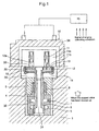
- FIG.1 is a longitudinal sectional view of a first embodiment of the electromagnetic valve device for an electromagnetic controlled unit injector for a diesel engine showing when the poppet valve has been moved up
- FIG.2 is a drawing as in FIG.1 of the first embodiment when the poppet valve has been moved down.
- through holes 13 are drilled in the armature 12 penetrating the armature 12 from the upper surface 12a thereof facing the end surface 11b of the solenoid core 11a to the rear surface near the outer periphery of the armature 12 such that distance from the center of the armature to each of the holes is the same or near the same to each other.
- a flexible thin plate valve 14 and made of stainless steel or plastic material to have spring function is attached to the rear surface of the armature 12.
- the thin plate valve 14 is fixed at its central part to the rear surface of the armature 12 by the fixing screw 35 together with the poppet valve 4 so that the central part is a fixed end and the peripheral part is a free end.
- the solenoid coil 11 When the solenoid coil 11 is energized by a signal sent from the solenoid controller 15 based on engine operating conditions such as engine rotation speed and engine loads, the armature 12 is attracted by attraction force generated by the energization toward the solenoid core 11a to allow the poppet valve 4 to be seated on a seat face 6 of the valve seat 5 (value of the small gap 33 is C when the poppet valve 4 is seated) as shown in FIG.1 . When the poppet valve 4 is seated on the seat face 6, a fuel passage 28 to the plunger room 3 is closed and fuel injection begins.
- FIG. 1 and 2 constituent parts the same as those of FIG.5 are denoted by the same reference numerals.
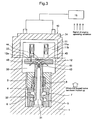
- FIG.3 is a longitudinal sectional view of a second embodiment of the invention of the electromagnetic valve device for an electromagnetic controlled unit injector for a diesel engine showing when the poppet valve has moved up
- FIG.4 is a drawing as in FIG.1 of the first embodiment when the poppet valve has moved down.
- a central through hole 44 and two outwardly downward slanting holes 41 communicating with the central hole 44 are provided to the armature 12.
- the upper end part of the poppet valve 4 is screwed into the rear side of the armature to be fixed thereto.
- a check valve 40 is provided at the upper end of the poppet valve 4 having the central hollow 31.
- the check valve 40 includes a spherical valve body 42 and a return spring 43 energizing the spherical valve body 42 upward.
- the check valve 40 opens and closes the central hole 44 and slanting holes 41 and also opens and closes the opening of the central hollow 31 at the upper end of the poppet vale 4.
- the spherical valve body 42 of the check valve opens the central hole 44 and slanting holes 41 when pressure above the upper surface 12a of the armature 12 rises as mentioned later.
- the solenoid coil 11 When the solenoid coil 11 is energized by a signal sent from the solenoid controller 15 based on engine operating conditions such as engine rotation speed and engine loads, the armature 12 is attracted by attraction force generated by the energization toward the solenoid core 11a to allow the poppet valve 4 to be seated on a seat face 6 of the valve seat 5 (value of the small gap 33 is C when the poppet valve 4 is seated) as shown in FIG.3 .
- the poppet valve 4 When the poppet valve 4 is seated on the seat face 6 and closes the fuel passage 28, a fuel passage 28 to the plunger room 3 is closed and fuel injection begins.
- spherical valve body 42 of the check valve 40 provided at the upper end of the poppet valve 4 is pushed down by the difference between the positive pressure in the small gap 33 and the negative pressure in the central hollow 31 against spring force of the return spring 42, and the central hole 44 is opened.
- fluid in the small gap 33 flows through the central hole 44 and slanted holes 41 into the armature room 30 and pressure in the small gap 33 is bled in to the armature room 30.
- FIG.3 and 4 the same constituent parts as those of FIG.5 are denoted by the same reference numerals.
- space for providing a communicating passage and a check valve is not needed to be provided in the casing at a side of the armature as is in the prior art disclosed in the patent literature 1, and the electromagnetic valve device 10 of compact and requiring less installation space and having effect mentioned above can be obtained, by composing such that through holes 13 are provided near the peripheral part of the flat armature 12 to penetrate the armature 12 from the upper surface 12a to the rear surface thereof and the thin plate valve 14 is attached to the rear surface of the armature 12 to cover the holes 13 in the first embodiment, or the central hole 44 and slanting holes 41 are formed in the armature 12 and the poppet valve 4 is screwed into the armature 12 at the upper end part of the poppet valve 4 where the check valve 40 is provided to open or close the central hole 44 in the second embodiment.
- the outer periphery of the armature slides contacting to the armature guide surface of the valve body liquid tight as is in the prior art disclosed in the patent literature 1, so a large gap is permitted to be provided between the outer periphery of the armature and the inner surface of the casing surrounding the armature. Therefore, high machining accuracy is not needed in machining the outer periphery of the armature and inner surface of the casing surrounding the armature as is in the patent document 1, and machining cost can be reduced.
- pressure in the small gap between the end surface of the solenoid core and the upper surface of the armature facing the end surface of the solenoid core increases as the armature is attracted upward to allow the poppet valve to be closed
- the check valve provided at the upper end of the poppet valve screwed into the armature opens the center hole at the top of the poppet valve the raised pressure in the small gap to allow fluid in the small gap to flow through the central hole and slanted holes communicating to the center hole, and pressure in the small gap is bled in to the armature room.
- space for providing a communicating passage and a check valve is not needed to be provided in the casing at a side of the armature as is in the prior art disclosed in the patent literature 1, and an electromagnetic valve device of compact and requiring less installation space and having effect mentioned above can be obtained, by composing such that through holes are provided near the peripheral part of the platy armature to penetrate the armature from the upper surface to the rear surface thereof and a central hole and slanting holes communicating to the central hole are formed in the armature and the poppet valve is screwed into the armature at the upper end part thereof where a check valve is provided.
Claims (2)
- Dispositif de soupape électromagnétique (10) comportant une armature plate (12) reliée à un corps de soupape (4) pour l'ouverture et la fermeture d'un passage de fluide (28), un dispositif de solenoïde destiné à attirer ladite armature grâce à une force d'attraction générée en excitant une bobine de solenoïde (11) dudit dispositif de solenôide en permettant audit corps de soupape (4) de fermer ledit passage de fluide (28) et en libérant la force d'attraction en désexcitant la bobine de solenoïde (11) en permettant audit corps de soupape (4) d'être ramené vers une position d'ouverture dans laquelle le corps de soupape ouvre ledit passage de fluide (28), et un ressort de rappel (8) destiné à pousser ledit corps de soupape (4) vers ladite position d'ouverture, caractérisé en ce que des trous débouchants (44) sont percés dans ladite armature (12) en pénétrant depuis une surface avant (12a) faisant face à une surface d'extrémité (11b) dudit dispositif de solenoïde jusqu'à une surface arrière, un clapet anti-retour (40) est prévu au niveau d'une partie de raccordement de ladite armature (12) audit corps de soupape (4) afin d'ouvrir ou fermer lesdits trous (44) de telle sorte qu'un petit espace entre ladite face d'extrémité (11b) dudit dispositif de solenoïde et ladite surface avant (12a) de ladite armature est en communication avec ou déconnecté d'une chambre d'armature (30) où ladite armature (12) se trouve, de sorte que, quand ladite armature (12) est attirée par ledit dispositif de solénoïde afin d'être déplacé vers le haut, ledit clapet anti-retour (40) ouvre lesdits trous (44) en étant poussé par une pression dans ledit petit espace (33) accrue par le mouvement vers le haut de ladite armature (12) aidé par une pression négative générée dans une cavité centrale (31) d'une soupape à tige en tant que dit corps de soupape (4) du fait d'un mouvement vers le haut de celui-ci de telle sorte que ledit petit espace (33) est amené en communication avec ladite chambre d'armature (30), et quand ledit corps de soupape (4) est abaissé par ledit ressort de rappel (8), ledit clapet anti-retour (40) ferme lesdits trous (44) en étant poussé par un ressort de rappel (43) dudit clapet anti-retour (44) aidé par une pression positive générée dans ladite cavité centrale (31) de ladite soupape à tige (4) du fait d'un mouvement vers le bas de celui-ci de telle sorte que ledit petit espace (33) n'est plus en communication avec ladite chambre d'armature (30).
- Appareil d'injection de carburant (100) pour des moteurs équipés d'un dispositif de soupape électromagnétique (10) selon la revendication 1, caractérisé en ce que l'appareil est composé de telle sorte qu'une chambre de plongeur (3) est déconnectée de ou en communication avec un passage d'alimentation/retour de carburant (28) quand une soupape à tige (4) en tant que dit corps de soupape repose sur ou est écartée d'une face de siège (6) d'un siège de soupape (5), de sorte qu'une injection de carburant commence quand ledit dispositif de solenoïde est excité de telle sorte que ladite soupape à tige ferme ledit passage de fluide (28) afin d'arrêter la communication entre ladite chambre de plongeur (3) et ledit passage d'alimentation/retour de carburant (28), et une injection de carburant se termine quand ledit dispositif de solénoïde est désexcité de telle sorte que ladite soupape à tige (4) ouvre ledit passage de fluide (28) en étant poussée par ledit ressort de rappel (8) afin d'amener ladite chambre de plongeur (3) en communication avec ledit passage d'alimentation/retour de carburant (28).
Applications Claiming Priority (1)
| Application Number | Priority Date | Filing Date | Title |
|---|---|---|---|
| JP2006342183A JP4719140B2 (ja) | 2006-12-20 | 2006-12-20 | 電磁弁装置及びこれを備えたエンジンの燃料噴射装置 |
Publications (3)
| Publication Number | Publication Date |
|---|---|
| EP1944501A2 EP1944501A2 (fr) | 2008-07-16 |
| EP1944501A3 EP1944501A3 (fr) | 2008-12-10 |
| EP1944501B1 true EP1944501B1 (fr) | 2010-01-20 |
Family
ID=39430088
Family Applications (1)
| Application Number | Title | Priority Date | Filing Date |
|---|---|---|---|
| EP07111459A Active EP1944501B1 (fr) | 2006-12-20 | 2007-06-29 | Dispositif de valve électromagnétique et appareil d'injection de carburant doté du dispositif de valve |
Country Status (5)
| Country | Link |
|---|---|
| US (1) | US7383819B1 (fr) |
| EP (1) | EP1944501B1 (fr) |
| JP (1) | JP4719140B2 (fr) |
| AT (1) | ATE455953T1 (fr) |
| DE (1) | DE602007004429D1 (fr) |
Families Citing this family (11)
| Publication number | Priority date | Publication date | Assignee | Title |
|---|---|---|---|---|
| JP5101456B2 (ja) | 2008-10-21 | 2012-12-19 | 三菱重工業株式会社 | ソレノイド式電磁弁装置 |
| ATE528499T1 (de) * | 2008-11-19 | 2011-10-15 | Delphi Tech Holding Sarl | Ankeranordnung |
| EP2322797B1 (fr) * | 2009-11-12 | 2012-10-31 | Delphi Technologies Holding S.à.r.l. | L'armature d'un actionneur de solénoide |
| DE102011075303A1 (de) * | 2011-05-05 | 2012-11-08 | Robert Bosch Gmbh | Elektromagnetische Betätigungseinrichtung, insbesondere zum Betreiben einer Pumpe |
| WO2013038472A1 (fr) * | 2011-09-12 | 2013-03-21 | トヨタ自動車株式会社 | Appareil de réglage de moteur à combustion interne |
| WO2013186859A1 (fr) | 2012-06-12 | 2013-12-19 | トヨタ自動車株式会社 | Électrovalve normalement fermée |
| DE102015006517A1 (de) * | 2015-04-01 | 2016-10-06 | Cummins Emission Solutions Inc. | Ventilmagnetschalter |
| DE102015223165A1 (de) * | 2015-11-24 | 2017-05-24 | Robert Bosch Gmbh | Elektromagnetisch ansteuerbares Saugventil für eine Hochdruckpumpe, Hochdruckpumpe |
| CN107420225B (zh) * | 2017-06-28 | 2023-05-30 | 哈尔滨工程大学 | 一种轴向进气的集成式环歧管壁面气体燃料喷射混合装置 |
| JP6797085B2 (ja) * | 2017-07-10 | 2020-12-09 | ヤンマーパワーテクノロジー株式会社 | 燃料噴射ポンプ |
| GB2574863B (en) * | 2018-06-21 | 2020-10-28 | Delphi Tech Ip Ltd | Valve assembly for a fuel injector having armature with flow passages |
Family Cites Families (18)
| Publication number | Priority date | Publication date | Assignee | Title |
|---|---|---|---|---|
| DE2948874A1 (de) * | 1979-12-05 | 1981-06-11 | Robert Bosch Gmbh, 7000 Stuttgart | Elektromagnetisch betaetigbares ventil |
| FR2569241A1 (fr) * | 1984-03-05 | 1986-02-21 | Mesenich Gerhard | Soupape d'injection electromagnetique comportant un dispositif pour atomiser le carburant au moyen d'un courant d'air |
| US5082180A (en) * | 1988-12-28 | 1992-01-21 | Diesel Kiki Co., Ltd. | Electromagnetic valve and unit fuel injector with electromagnetic valve |
| US5005803A (en) * | 1988-12-29 | 1991-04-09 | Applied Power Inc. | High response, compact solenoid two-way valve |
| JPH05248300A (ja) * | 1992-03-04 | 1993-09-24 | Zexel Corp | 燃料噴射装置 |
| EP0671558B1 (fr) * | 1992-03-26 | 1998-09-02 | Zexel Corporation | Dispositif d'injection de carburant |
| JP3021182B2 (ja) * | 1992-04-20 | 2000-03-15 | 三菱重工業株式会社 | 電磁式ユニットインジェクタ |
| JPH0614464A (ja) | 1992-06-24 | 1994-01-21 | Toshiba Corp | 発電機の経済負荷配分装置 |
| JPH0642372A (ja) * | 1992-07-23 | 1994-02-15 | Zexel Corp | 燃料噴射制御装置 |
| US5443047A (en) * | 1993-04-09 | 1995-08-22 | Zexel Corporation | Fuel injection system |
| JPH07279792A (ja) | 1994-04-01 | 1995-10-27 | Toyota Motor Corp | 電磁弁装置 |
| DE10119984A1 (de) * | 2001-04-24 | 2002-10-31 | Bosch Gmbh Robert | Kraftstoffeinspritzeinrichtung für eine Brennkraftmaschine |
| US6758416B2 (en) * | 2002-08-30 | 2004-07-06 | Robert Bosch Gmbh | Fuel injector having an expansion tank accumulator |
| JP2005105923A (ja) * | 2003-09-30 | 2005-04-21 | Bosch Automotive Systems Corp | 燃料噴射弁 |
| JP4026592B2 (ja) * | 2003-12-24 | 2007-12-26 | 株式会社デンソー | 燃料噴射弁 |
| JP4064934B2 (ja) * | 2004-02-27 | 2008-03-19 | 三菱重工業株式会社 | 電磁弁装置 |
| JP4634285B2 (ja) * | 2005-02-24 | 2011-02-16 | 三菱重工業株式会社 | ポペット弁を備えた電磁制御燃料噴射装置 |
| US7255091B2 (en) * | 2005-05-31 | 2007-08-14 | Caterpillar, Inc. | Fuel injector control system and method |
-
2006
- 2006-12-20 JP JP2006342183A patent/JP4719140B2/ja active Active
-
2007
- 2007-06-25 US US11/819,092 patent/US7383819B1/en active Active
- 2007-06-29 EP EP07111459A patent/EP1944501B1/fr active Active
- 2007-06-29 AT AT07111459T patent/ATE455953T1/de active
- 2007-06-29 DE DE602007004429T patent/DE602007004429D1/de active Active
Also Published As
| Publication number | Publication date |
|---|---|
| US20080149071A1 (en) | 2008-06-26 |
| DE602007004429D1 (de) | 2010-03-11 |
| EP1944501A2 (fr) | 2008-07-16 |
| JP4719140B2 (ja) | 2011-07-06 |
| ATE455953T1 (de) | 2010-02-15 |
| US7383819B1 (en) | 2008-06-10 |
| JP2008151082A (ja) | 2008-07-03 |
| EP1944501A3 (fr) | 2008-12-10 |
Similar Documents
| Publication | Publication Date | Title |
|---|---|---|
| EP1944501B1 (fr) | Dispositif de valve électromagnétique et appareil d'injection de carburant doté du dispositif de valve | |
| EP1783356B1 (fr) | Soupape d'injection de carburant | |
| US5720318A (en) | Solenoid actuated miniservo spool valve | |
| CN101535625B (zh) | 用于喷射燃料的喷射器 | |
| US5474234A (en) | Electrically controlled fluid control valve of a fuel injector system | |
| US5605289A (en) | Fuel injector with spring-biased control valve | |
| JPH08240166A (ja) | 燃料噴射装置 | |
| WO2000055490A1 (fr) | Injecteur de carburant | |
| JP4478944B2 (ja) | 流体調量弁およびそれを用いた燃料噴射ポンプ | |
| US7509948B1 (en) | Variable displacement pump with an anti-stiction device | |
| JP2015524897A (ja) | 流れ制御システム | |
| JPH11508345A (ja) | 燃料ポンプおよびその作動方法 | |
| EP1362991B1 (fr) | Dispositif de commande de soupape pour moteur à combustion interne | |
| US6021963A (en) | Cartridge control valve with top mounted solenoid and flat valve seat for a fuel injector | |
| JPWO2018221077A1 (ja) | 電磁弁、電磁吸入弁機構、及び高圧燃料ポンプ | |
| GB2336628A (en) | A fuel injector, for an I.C. engine, having a three way two position needle control valve | |
| JP5002023B2 (ja) | カップラを備えた燃料インジェクタ | |
| EP1696117B1 (fr) | Injecteur de carburant à commande électromagnétique | |
| EP1793120A1 (fr) | Soupape d'un injecteur | |
| JP4321448B2 (ja) | 弁制御機構 | |
| JP2005256759A (ja) | 燃料噴射弁 | |
| EP0995898A2 (fr) | Système de carburant | |
| US20210164429A1 (en) | Injector for injecting fuel | |
| JP2003214282A (ja) | 燃料噴射装置のための二重切換弁 | |
| JPH057498Y2 (fr) |
Legal Events
| Date | Code | Title | Description |
|---|---|---|---|
| PUAI | Public reference made under article 153(3) epc to a published international application that has entered the european phase |
Free format text: ORIGINAL CODE: 0009012 |
|
| AK | Designated contracting states |
Kind code of ref document: A2 Designated state(s): AT BE BG CH CY CZ DE DK EE ES FI FR GB GR HU IE IS IT LI LT LU LV MC MT NL PL PT RO SE SI SK TR |
|
| AX | Request for extension of the european patent |
Extension state: AL BA HR MK RS |
|
| PUAL | Search report despatched |
Free format text: ORIGINAL CODE: 0009013 |
|
| AK | Designated contracting states |
Kind code of ref document: A3 Designated state(s): AT BE BG CH CY CZ DE DK EE ES FI FR GB GR HU IE IS IT LI LT LU LV MC MT NL PL PT RO SE SI SK TR |
|
| AX | Request for extension of the european patent |
Extension state: AL BA HR MK RS |
|
| 17P | Request for examination filed |
Effective date: 20090526 |
|
| GRAP | Despatch of communication of intention to grant a patent |
Free format text: ORIGINAL CODE: EPIDOSNIGR1 |
|
| AKX | Designation fees paid |
Designated state(s): AT DE FR GB |
|
| GRAS | Grant fee paid |
Free format text: ORIGINAL CODE: EPIDOSNIGR3 |
|
| GRAA | (expected) grant |
Free format text: ORIGINAL CODE: 0009210 |
|
| AK | Designated contracting states |
Kind code of ref document: B1 Designated state(s): AT DE FR GB |
|
| REG | Reference to a national code |
Ref country code: GB Ref legal event code: FG4D |
|
| REF | Corresponds to: |
Ref document number: 602007004429 Country of ref document: DE Date of ref document: 20100311 Kind code of ref document: P |
|
| PLBE | No opposition filed within time limit |
Free format text: ORIGINAL CODE: 0009261 |
|
| STAA | Information on the status of an ep patent application or granted ep patent |
Free format text: STATUS: NO OPPOSITION FILED WITHIN TIME LIMIT |
|
| 26N | No opposition filed |
Effective date: 20101021 |
|
| REG | Reference to a national code |
Ref country code: FR Ref legal event code: PLFP Year of fee payment: 10 |
|
| REG | Reference to a national code |
Ref country code: FR Ref legal event code: PLFP Year of fee payment: 11 |
|
| REG | Reference to a national code |
Ref country code: FR Ref legal event code: PLFP Year of fee payment: 12 |
|
| REG | Reference to a national code |
Ref country code: DE Ref legal event code: R082 Ref document number: 602007004429 Country of ref document: DE Representative=s name: CBDL PATENTANWAELTE, DE Ref country code: DE Ref legal event code: R081 Ref document number: 602007004429 Country of ref document: DE Owner name: MITSUBISHI HEAVY INDUSTRIES ENGINE & TURBOCHAR, JP Free format text: FORMER OWNER: MITSUBISHI HEAVY INDUSTRIES, LTD., TOKYO, JP |
|
| REG | Reference to a national code |
Ref country code: GB Ref legal event code: 732E Free format text: REGISTERED BETWEEN 20180913 AND 20180919 |
|
| REG | Reference to a national code |
Ref country code: AT Ref legal event code: PC Ref document number: 455953 Country of ref document: AT Kind code of ref document: T Owner name: MITSUBISHI HEAVY INDUSTRIES ENGINE & TURBOCHAR, JP Effective date: 20181019 |
|
| PGFP | Annual fee paid to national office [announced via postgrant information from national office to epo] |
Ref country code: GB Payment date: 20200618 Year of fee payment: 14 |
|
| PGFP | Annual fee paid to national office [announced via postgrant information from national office to epo] |
Ref country code: AT Payment date: 20200526 Year of fee payment: 14 |
|
| PGFP | Annual fee paid to national office [announced via postgrant information from national office to epo] |
Ref country code: FR Payment date: 20210513 Year of fee payment: 15 |
|
| REG | Reference to a national code |
Ref country code: AT Ref legal event code: MM01 Ref document number: 455953 Country of ref document: AT Kind code of ref document: T Effective date: 20210629 |
|
| GBPC | Gb: european patent ceased through non-payment of renewal fee |
Effective date: 20210629 |
|
| PG25 | Lapsed in a contracting state [announced via postgrant information from national office to epo] |
Ref country code: GB Free format text: LAPSE BECAUSE OF NON-PAYMENT OF DUE FEES Effective date: 20210629 Ref country code: AT Free format text: LAPSE BECAUSE OF NON-PAYMENT OF DUE FEES Effective date: 20210629 |
|
| REG | Reference to a national code |
Ref country code: DE Ref legal event code: R082 Ref document number: 602007004429 Country of ref document: DE Representative=s name: CBDL PATENTANWAELTE GBR, DE |
|
| PG25 | Lapsed in a contracting state [announced via postgrant information from national office to epo] |
Ref country code: FR Free format text: LAPSE BECAUSE OF NON-PAYMENT OF DUE FEES Effective date: 20220630 |
|
| PGFP | Annual fee paid to national office [announced via postgrant information from national office to epo] |
Ref country code: DE Payment date: 20230502 Year of fee payment: 17 |