EP1938927A2 - Elément d'entraînement sur une machine-outil manuelle - Google Patents
Elément d'entraînement sur une machine-outil manuelle Download PDFInfo
- Publication number
- EP1938927A2 EP1938927A2 EP07021234A EP07021234A EP1938927A2 EP 1938927 A2 EP1938927 A2 EP 1938927A2 EP 07021234 A EP07021234 A EP 07021234A EP 07021234 A EP07021234 A EP 07021234A EP 1938927 A2 EP1938927 A2 EP 1938927A2
- Authority
- EP
- European Patent Office
- Prior art keywords
- polygonal
- pin
- plug
- tool
- recess
- Prior art date
- Legal status (The legal status is an assumption and is not a legal conclusion. Google has not performed a legal analysis and makes no representation as to the accuracy of the status listed.)
- Withdrawn
Links
Images


Classifications
-
- B—PERFORMING OPERATIONS; TRANSPORTING
- B25—HAND TOOLS; PORTABLE POWER-DRIVEN TOOLS; MANIPULATORS
- B25B—TOOLS OR BENCH DEVICES NOT OTHERWISE PROVIDED FOR, FOR FASTENING, CONNECTING, DISENGAGING OR HOLDING
- B25B23/00—Details of, or accessories for, spanners, wrenches, screwdrivers
- B25B23/0007—Connections or joints between tool parts
- B25B23/0035—Connection means between socket or screwdriver bit and tool
Definitions
- the invention relates to a rotating during operation output part on a power tool, to which in the axial direction a tool or a tool holder is detachably plugged, which is or in the infected state via a polygonal arrangement in Drehmit Spotifyeingriff with the driven part.
- Hand tool machines in particular for screwing in and unscrewing screws, are generally known, for example, in the form of cordless screwdrivers or line-powered screwdrivers.
- the output part usually formed by the output shaft has a frontally open, designed as a polygonal recess plug recess into which a rotary tool, in particular a screwdriver bit, can be inserted with its multi-edge shaft.
- the driven part or the output shaft forming this has a plug-in pin in the form of a polygonal pin on which a rotary tool, in this case a socket wrench, also called socket, can be plugged, which has a polygonal socket fitting on the polygon.
- the present invention is therefore based on the object to provide a driven part on a hand tool, which allows a possible universal use.
- the output member both a outgoing from its end plug recess formed at least over part of its length as Mehrkantaus simplifiedung for inserting the polygonal shaft of a tool as well as a plug-in recess coaxial spigot, at least over part of his Length is formed as a polygonal pin, for attaching a provided with a matching polygonal pin polygonal socket tool or tool holder forms.
- hand tool is suitable for both types of use - using a bit and a socket wrench and without adapter immediately usable by either the polygonal shaft of each bit or the like tool inserted into the MehrkantausEnglishung or the polygonal socket of the socket wrench on the same output part is plugged.
- a tool holder can be infected, which in turn serves to hold a tool.
- the inventive measures are easy to implement and bring virtually no overhead with respect to a suitable only for one of the applications output part with it.
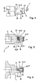
- the resulting from the drawing output part 1 is rotatably connected to the output shaft of a hand tool, not shown, so that it is arranged coaxially with the output shaft and forms the front end of the output train. During operation, the output part 1 rotates together with the output shaft about the axis of rotation axis 2.
- a tool 3 with a polygonal shaft 4 in particular in the form of a bit, for example a screwdriver bit, or a tool 5 with a polygonal receptacle 6, in particular a socket wrench, can be detachably connected in the axial direction to the driven part 1.
- the two tools 3, 5 are shown in the remote from the driven part 1 state.
- the plugging takes place in the axial direction from the front in the direction of the respective arrow.
- the respective tool 3, 5 via a polygonal arrangement in rotational driving engagement with the driven part. 1
- the tool 3 formed in the illustrated case of one bit then has to the polygonal shaft 4 in the infected state before the stripping section 1 above functional section 7, whose front end is adapted to each screw on or inexpensiveunautende screw, so that the functional portion 7 in rotational driving engagement can be brought with the screw.
- the other tool 5 has, it is formed by a socket wrench, then to its the polygonal receptacle 6 containing lot 8 a sleeve-shaped lot 9 with one of the polygonal receptacle 6 opposite end outgoing, polygonal Steck whylaus brieflyung, which can be firmly attached to the polygonal head of a screw or a nut rotation, so that the screw or nut can be tightened or loosened.
- a correspondingly adapted tool holder (not shown) can be connected to the output part 1, which in turn serves to hold a tool.
- the driven part 1 has an outgoing from its end face 11 plug-in recess 12 for insertion of the polygonal shaft 4 of the tool 3.
- the plug-in recess 12 is formed over at least part of its length as a polygonal recess 13, which is adapted in cross-section to the tool polygonal shaft 4, so that there is a rotationsmit Spotifyfeste connection in the inserted state.
- the driven part 1 further forms a plug-in recess 12 coaxial plug-in pin 14 which is formed at least over part of its length as a polygonal pin 15.
- the other tool 5 can be plugged with its polygonal receptacle 6, whose cross-section is adapted to the cross section of the polygonal pin 15.
- the plug-in recess 12 assigned to the tool 3 runs in the interior of the plug-in spigot 14 associated with the other tool 5.
- resilient latching means 16 are arranged which protrude slightly into the polygonal recess 13 and serve for releasable locking of the inserted polygonal shaft 4 of the tool 3.
- the resilient locking means 16 is a slotted spring ring 17 inserted in an annular groove on the wall of the plug recess 12 FIG. 1
- the spring ring 17 conceals the polygonal contour of the polygonal recess 13.
- the spring ring 17 is assigned a circumferential detent groove 18 on the outer circumference of the polygonal shaft 4 of the tool 3. When inserting the polygonal shaft 4, the spring ring 17 widens first and then snaps into the locking groove 18, so that the tool 3 is held in the axial direction.
- the spring ring 17 is suitably made of wire material.
- resilient latching means 16 could also be spring-mounted locking means, for example in the form of at least one resiliently mounted in the radial direction on the plug pin 14 locking ball (not shown).
- the plugged tool 5 holds securely on the plug-14, at least one resilient or resiliently mounted, on the circumference of the spigot 14 projecting locking element 19 is arranged on the plug pin 14, which comes with the tool 5 in releasable Verrastungseingriff.
- a single locking element 19 in the form of a detent ball 20 is present, which is acted upon by a coil spring 21 to the outside.
- the coil spring 21 and the detent ball 20 are arranged in a transverse bore 22 of the spigot 14, which is formed as a blind bore.
- the coil spring 21 is supported on the one hand at the bottom of the transverse bore 22 and on the other hand on the detent ball 20 from.
- the outer mouth of the transverse bore 22 is slightly tapered, so that the detent ball 20 is retained in the transverse bore 22.
- the detent ball 20 is on formed as a polygon 15 portion of the spigot 14 and thereby on one of the flat sides of the polygonal pin 15th
- the detent ball 20 is associated with a latching recess 23 on the peripheral surface of the polygonal receptacle 6 of the tool 5.
- the latching recess 23 may be formed, for example, by a circumferential latching groove 24, so that when plugging the tool 5 does not have to be paid attention to its rotational position relative to the spigot 14.
- the locking ball 20 When attaching the locking ball 20 is initially displaced from the end face of the tool 3 to the radially inner. If the latching recess 23 reaches the latching ball 20, the latching ball 20 snaps outwardly into the latching recess 23 under the force of the helical spring 21, whereby an axial cohesion is achieved.
- the plug-in pin 14 has an outgoing from the end face 11 of the driven part end portion 25 with a cylindrical Au- ⁇ engestalt, to which the formed as a polygon 15 portion of the spigot 14 connects.
- the cylindrical end region 25 has a smaller diameter than the polygonal pin 15 in the exemplary embodiment.
- the tool polygonal shaft 4 is formed as a hex shank.
- the polygonal recess 13 has a suitable cross section for receiving such a polygonal shaft.
- the polygonal pin 15 is a square pin in the usual way. Accordingly, it is in the recording 6 of the tool 5 to a square polygonal recording.
- the polygonal pin 15 therefore forms four flat sides 26, 27, 28, 29th
- Another expedient measure is that on at least one flat side 26, 27, 28, 29 of the polygon spigot 15, in the embodiment on all flat sides, a recess for releasably locking a plugged tool holder is arranged.
Applications Claiming Priority (1)
| Application Number | Priority Date | Filing Date | Title |
|---|---|---|---|
| DE200610061757 DE102006061757A1 (de) | 2006-12-28 | 2006-12-28 | Abtriebsteil an einer Handwerkzeugmaschine |
Publications (2)
| Publication Number | Publication Date |
|---|---|
| EP1938927A2 true EP1938927A2 (fr) | 2008-07-02 |
| EP1938927A3 EP1938927A3 (fr) | 2010-02-17 |
Family
ID=39166372
Family Applications (1)
| Application Number | Title | Priority Date | Filing Date |
|---|---|---|---|
| EP07021234A Withdrawn EP1938927A3 (fr) | 2006-12-28 | 2007-10-31 | Elément d'entraînement sur une machine-outil manuelle |
Country Status (2)
| Country | Link |
|---|---|
| EP (1) | EP1938927A3 (fr) |
| DE (1) | DE102006061757A1 (fr) |
Cited By (6)
| Publication number | Priority date | Publication date | Assignee | Title |
|---|---|---|---|---|
| WO2011104109A1 (fr) * | 2010-02-25 | 2011-09-01 | Robert Bosch Gmbh | Machine-outil à main |
| WO2011104105A1 (fr) * | 2010-02-25 | 2011-09-01 | Robert Bosch Gmbh | Machine-outil à main |
| WO2011154230A1 (fr) * | 2010-06-09 | 2011-12-15 | Robert Bosch Gmbh | Machine-outil à main munie d'un raccordement d'outil |
| CN113825594A (zh) * | 2019-06-06 | 2021-12-21 | Wto资产管理有限公司 | 用于静止的和受驱动的工具架的操作钥匙 |
| SE2030350A1 (en) * | 2020-12-01 | 2022-06-02 | Atlas Copco Ind Technique Ab | Torque transferring device for use with a power tool |
| US11969861B2 (en) | 2020-12-01 | 2024-04-30 | Atlas Copco Industrial Technique Ab | Torque transferring device for use with a power tool |
Families Citing this family (1)
| Publication number | Priority date | Publication date | Assignee | Title |
|---|---|---|---|---|
| DE102022100891A1 (de) | 2022-01-17 | 2023-07-20 | Wera Werkzeuge Gmbh | Schraubwerkzeug für Nüsse und Bits |
Citations (2)
| Publication number | Priority date | Publication date | Assignee | Title |
|---|---|---|---|---|
| US6363819B1 (en) * | 2000-09-13 | 2002-04-02 | Hung Yu Industrial Co., Ltd. | Knockdown hand tool structure |
| DE202005015031U1 (de) * | 2005-09-22 | 2006-04-27 | Chen, Chang-Ying, Ta Li | Mehrzweck-Werkzeugkopf |
-
2006
- 2006-12-28 DE DE200610061757 patent/DE102006061757A1/de not_active Withdrawn
-
2007
- 2007-10-31 EP EP07021234A patent/EP1938927A3/fr not_active Withdrawn
Patent Citations (2)
| Publication number | Priority date | Publication date | Assignee | Title |
|---|---|---|---|---|
| US6363819B1 (en) * | 2000-09-13 | 2002-04-02 | Hung Yu Industrial Co., Ltd. | Knockdown hand tool structure |
| DE202005015031U1 (de) * | 2005-09-22 | 2006-04-27 | Chen, Chang-Ying, Ta Li | Mehrzweck-Werkzeugkopf |
Cited By (11)
| Publication number | Priority date | Publication date | Assignee | Title |
|---|---|---|---|---|
| WO2011104109A1 (fr) * | 2010-02-25 | 2011-09-01 | Robert Bosch Gmbh | Machine-outil à main |
| WO2011104105A1 (fr) * | 2010-02-25 | 2011-09-01 | Robert Bosch Gmbh | Machine-outil à main |
| CN102762327A (zh) * | 2010-02-25 | 2012-10-31 | 罗伯特·博世有限公司 | 手持式工具机 |
| CN102762327B (zh) * | 2010-02-25 | 2016-07-06 | 罗伯特·博世有限公司 | 手持式工具机 |
| WO2011154230A1 (fr) * | 2010-06-09 | 2011-12-15 | Robert Bosch Gmbh | Machine-outil à main munie d'un raccordement d'outil |
| US9718173B2 (en) | 2010-06-09 | 2017-08-01 | Robert Bosch Gmbh | Handheld machine tool having a tool holding fixture |
| CN113825594A (zh) * | 2019-06-06 | 2021-12-21 | Wto资产管理有限公司 | 用于静止的和受驱动的工具架的操作钥匙 |
| CN113825594B (zh) * | 2019-06-06 | 2023-05-16 | Wto资产管理有限公司 | 用于静止的和受驱动的工具架的操作钥匙 |
| SE2030350A1 (en) * | 2020-12-01 | 2022-06-02 | Atlas Copco Ind Technique Ab | Torque transferring device for use with a power tool |
| SE545106C2 (en) * | 2020-12-01 | 2023-04-04 | Atlas Copco Ind Technique Ab | Torque transferring device for use with a power tool |
| US11969861B2 (en) | 2020-12-01 | 2024-04-30 | Atlas Copco Industrial Technique Ab | Torque transferring device for use with a power tool |
Also Published As
| Publication number | Publication date |
|---|---|
| EP1938927A3 (fr) | 2010-02-17 |
| DE102006061757A1 (de) | 2008-07-03 |
Similar Documents
| Publication | Publication Date | Title |
|---|---|---|
| EP2262601B1 (fr) | Machine-outil a main | |
| DE102010055429A1 (de) | Kupplung für ein rotierendes Schneidwerkzeug mit Schnellwechseleinsatz | |
| WO2016135216A1 (fr) | Machine-outil portative | |
| EP2188094B1 (fr) | Machine-outil avec un porte-outil | |
| EP2771151A1 (fr) | Machine-outil à main | |
| EP1938927A2 (fr) | Elément d'entraînement sur une machine-outil manuelle | |
| EP1944838A1 (fr) | Outil destiné à serrer ou desserrer des boulonnages de câbles | |
| EP1819470B1 (fr) | Machine-outil portative, notamment perceuse ou visseuse | |
| WO2001089770A1 (fr) | Tete receptrice destinee a un outil comportant une pointe d'actionnement plate ou a plusieurs pans | |
| EP2423553A2 (fr) | Collier de serrage doté d'une vis de serrage, vis de serrage et outil d'entraînement de la vis de serrage | |
| DE102007003985A1 (de) | Schiebhülse zur Anbringung auf dem Schaft eines Schraubendreherwerkzeugs | |
| EP1262266A1 (fr) | Dispositif de fixation | |
| DE102020107326B4 (de) | Verlängerbarer Schraubenschlüssel | |
| DE102004028981B4 (de) | Drehmomentverstellbares Werkzeug | |
| DE3807439A1 (de) | Als schraubenschluessel verwendbare vorrichtung zum sprengen einer schraubenmutter | |
| DE19920544C2 (de) | Gelenk für ein Werkzeug | |
| EP2345496A1 (fr) | Porte-outil | |
| DE3507684A1 (de) | Spannvorrichtung fuer handwerkzeugmaschinen | |
| DE202005009372U1 (de) | Aufspannfutter für Befestigungswerkzeuge | |
| DE102004011579B4 (de) | Spannfutter für Werkzeugeinsätze | |
| DE3616731C2 (fr) | ||
| DE102011009722A1 (de) | Adapterelement für einen Schraubenschlüssel | |
| DE3938244A1 (de) | Bohr- oder schraubendrehermaschine | |
| DE102004001580B3 (de) | Vorrichtung zum Verbinden eines Schleifwerkzeugs mit einer Werkzeugmaschine | |
| DE10308056A1 (de) | Spezialwerkzeug |
Legal Events
| Date | Code | Title | Description |
|---|---|---|---|
| PUAI | Public reference made under article 153(3) epc to a published international application that has entered the european phase |
Free format text: ORIGINAL CODE: 0009012 |
|
| AK | Designated contracting states |
Kind code of ref document: A2 Designated state(s): AT BE BG CH CY CZ DE DK EE ES FI FR GB GR HU IE IS IT LI LT LU LV MC MT NL PL PT RO SE SI SK TR |
|
| AX | Request for extension of the european patent |
Extension state: AL BA HR MK RS |
|
| PUAL | Search report despatched |
Free format text: ORIGINAL CODE: 0009013 |
|
| AK | Designated contracting states |
Kind code of ref document: A3 Designated state(s): AT BE BG CH CY CZ DE DK EE ES FI FR GB GR HU IE IS IT LI LT LU LV MC MT NL PL PT RO SE SI SK TR |
|
| AX | Request for extension of the european patent |
Extension state: AL BA HR MK RS |
|
| AKY | No designation fees paid | ||
| STAA | Information on the status of an ep patent application or granted ep patent |
Free format text: STATUS: THE APPLICATION IS DEEMED TO BE WITHDRAWN |
|
| 18D | Application deemed to be withdrawn |
Effective date: 20100818 |
|
| REG | Reference to a national code |
Ref country code: DE Ref legal event code: R108 Effective date: 20110201 Ref country code: DE Ref legal event code: 8566 |