EP1938927A2 - Output part of a hand tool - Google Patents
Output part of a hand tool Download PDFInfo
- Publication number
- EP1938927A2 EP1938927A2 EP07021234A EP07021234A EP1938927A2 EP 1938927 A2 EP1938927 A2 EP 1938927A2 EP 07021234 A EP07021234 A EP 07021234A EP 07021234 A EP07021234 A EP 07021234A EP 1938927 A2 EP1938927 A2 EP 1938927A2
- Authority
- EP
- European Patent Office
- Prior art keywords
- polygonal
- pin
- plug
- tool
- recess
- Prior art date
- Legal status (The legal status is an assumption and is not a legal conclusion. Google has not performed a legal analysis and makes no representation as to the accuracy of the status listed.)
- Withdrawn
Links
Images


Classifications
-
- B—PERFORMING OPERATIONS; TRANSPORTING
- B25—HAND TOOLS; PORTABLE POWER-DRIVEN TOOLS; MANIPULATORS
- B25B—TOOLS OR BENCH DEVICES NOT OTHERWISE PROVIDED FOR, FOR FASTENING, CONNECTING, DISENGAGING OR HOLDING
- B25B23/00—Details of, or accessories for, spanners, wrenches, screwdrivers
- B25B23/0007—Connections or joints between tool parts
- B25B23/0035—Connection means between socket or screwdriver bit and tool
Definitions
- the invention relates to a rotating during operation output part on a power tool, to which in the axial direction a tool or a tool holder is detachably plugged, which is or in the infected state via a polygonal arrangement in Drehmit Spotifyeingriff with the driven part.
- Hand tool machines in particular for screwing in and unscrewing screws, are generally known, for example, in the form of cordless screwdrivers or line-powered screwdrivers.
- the output part usually formed by the output shaft has a frontally open, designed as a polygonal recess plug recess into which a rotary tool, in particular a screwdriver bit, can be inserted with its multi-edge shaft.
- the driven part or the output shaft forming this has a plug-in pin in the form of a polygonal pin on which a rotary tool, in this case a socket wrench, also called socket, can be plugged, which has a polygonal socket fitting on the polygon.
- the present invention is therefore based on the object to provide a driven part on a hand tool, which allows a possible universal use.
- the output member both a outgoing from its end plug recess formed at least over part of its length as Mehrkantaus simplifiedung for inserting the polygonal shaft of a tool as well as a plug-in recess coaxial spigot, at least over part of his Length is formed as a polygonal pin, for attaching a provided with a matching polygonal pin polygonal socket tool or tool holder forms.
- hand tool is suitable for both types of use - using a bit and a socket wrench and without adapter immediately usable by either the polygonal shaft of each bit or the like tool inserted into the MehrkantausEnglishung or the polygonal socket of the socket wrench on the same output part is plugged.
- a tool holder can be infected, which in turn serves to hold a tool.
- the inventive measures are easy to implement and bring virtually no overhead with respect to a suitable only for one of the applications output part with it.
- the resulting from the drawing output part 1 is rotatably connected to the output shaft of a hand tool, not shown, so that it is arranged coaxially with the output shaft and forms the front end of the output train. During operation, the output part 1 rotates together with the output shaft about the axis of rotation axis 2.
- a tool 3 with a polygonal shaft 4 in particular in the form of a bit, for example a screwdriver bit, or a tool 5 with a polygonal receptacle 6, in particular a socket wrench, can be detachably connected in the axial direction to the driven part 1.
- the two tools 3, 5 are shown in the remote from the driven part 1 state.
- the plugging takes place in the axial direction from the front in the direction of the respective arrow.
- the respective tool 3, 5 via a polygonal arrangement in rotational driving engagement with the driven part. 1
- the tool 3 formed in the illustrated case of one bit then has to the polygonal shaft 4 in the infected state before the stripping section 1 above functional section 7, whose front end is adapted to each screw on or inexpensiveunautende screw, so that the functional portion 7 in rotational driving engagement can be brought with the screw.
- the other tool 5 has, it is formed by a socket wrench, then to its the polygonal receptacle 6 containing lot 8 a sleeve-shaped lot 9 with one of the polygonal receptacle 6 opposite end outgoing, polygonal Steck whylaus brieflyung, which can be firmly attached to the polygonal head of a screw or a nut rotation, so that the screw or nut can be tightened or loosened.
- a correspondingly adapted tool holder (not shown) can be connected to the output part 1, which in turn serves to hold a tool.
- the driven part 1 has an outgoing from its end face 11 plug-in recess 12 for insertion of the polygonal shaft 4 of the tool 3.
- the plug-in recess 12 is formed over at least part of its length as a polygonal recess 13, which is adapted in cross-section to the tool polygonal shaft 4, so that there is a rotationsmit Spotifyfeste connection in the inserted state.
- the driven part 1 further forms a plug-in recess 12 coaxial plug-in pin 14 which is formed at least over part of its length as a polygonal pin 15.
- the other tool 5 can be plugged with its polygonal receptacle 6, whose cross-section is adapted to the cross section of the polygonal pin 15.
- the plug-in recess 12 assigned to the tool 3 runs in the interior of the plug-in spigot 14 associated with the other tool 5.
- resilient latching means 16 are arranged which protrude slightly into the polygonal recess 13 and serve for releasable locking of the inserted polygonal shaft 4 of the tool 3.
- the resilient locking means 16 is a slotted spring ring 17 inserted in an annular groove on the wall of the plug recess 12 FIG. 1
- the spring ring 17 conceals the polygonal contour of the polygonal recess 13.
- the spring ring 17 is assigned a circumferential detent groove 18 on the outer circumference of the polygonal shaft 4 of the tool 3. When inserting the polygonal shaft 4, the spring ring 17 widens first and then snaps into the locking groove 18, so that the tool 3 is held in the axial direction.
- the spring ring 17 is suitably made of wire material.
- resilient latching means 16 could also be spring-mounted locking means, for example in the form of at least one resiliently mounted in the radial direction on the plug pin 14 locking ball (not shown).
- the plugged tool 5 holds securely on the plug-14, at least one resilient or resiliently mounted, on the circumference of the spigot 14 projecting locking element 19 is arranged on the plug pin 14, which comes with the tool 5 in releasable Verrastungseingriff.
- a single locking element 19 in the form of a detent ball 20 is present, which is acted upon by a coil spring 21 to the outside.
- the coil spring 21 and the detent ball 20 are arranged in a transverse bore 22 of the spigot 14, which is formed as a blind bore.
- the coil spring 21 is supported on the one hand at the bottom of the transverse bore 22 and on the other hand on the detent ball 20 from.
- the outer mouth of the transverse bore 22 is slightly tapered, so that the detent ball 20 is retained in the transverse bore 22.
- the detent ball 20 is on formed as a polygon 15 portion of the spigot 14 and thereby on one of the flat sides of the polygonal pin 15th
- the detent ball 20 is associated with a latching recess 23 on the peripheral surface of the polygonal receptacle 6 of the tool 5.
- the latching recess 23 may be formed, for example, by a circumferential latching groove 24, so that when plugging the tool 5 does not have to be paid attention to its rotational position relative to the spigot 14.
- the locking ball 20 When attaching the locking ball 20 is initially displaced from the end face of the tool 3 to the radially inner. If the latching recess 23 reaches the latching ball 20, the latching ball 20 snaps outwardly into the latching recess 23 under the force of the helical spring 21, whereby an axial cohesion is achieved.
- the plug-in pin 14 has an outgoing from the end face 11 of the driven part end portion 25 with a cylindrical Au- ⁇ engestalt, to which the formed as a polygon 15 portion of the spigot 14 connects.
- the cylindrical end region 25 has a smaller diameter than the polygonal pin 15 in the exemplary embodiment.
- the tool polygonal shaft 4 is formed as a hex shank.
- the polygonal recess 13 has a suitable cross section for receiving such a polygonal shaft.
- the polygonal pin 15 is a square pin in the usual way. Accordingly, it is in the recording 6 of the tool 5 to a square polygonal recording.
- the polygonal pin 15 therefore forms four flat sides 26, 27, 28, 29th
- Another expedient measure is that on at least one flat side 26, 27, 28, 29 of the polygon spigot 15, in the embodiment on all flat sides, a recess for releasably locking a plugged tool holder is arranged.
Abstract
Description
Die Erfindung betrifft ein beim Betrieb rotierendes Abtriebsteil an einer Handwerkzeugmaschine, an das in axialer Richtung ein Werkzeug oder ein Werkzeughalter lösbar ansteckbar ist, das bzw. der im angesteckten Zustand über eine Mehrkantanordnung in Rotationsmitnahmeeingriff mit dem Abtriebsteil steht.The invention relates to a rotating during operation output part on a power tool, to which in the axial direction a tool or a tool holder is detachably plugged, which is or in the infected state via a polygonal arrangement in Drehmitnahmeeingriff with the driven part.
Handwerkzeugmaschinen insbesondere zum Eindrehen und Ausdrehen von Schrauben sind beispielsweise in Gestalt von Akkuschraubern oder mit Netzstrom betriebenen Schraubern allgemein bekannt. Dabei weist das üblicherweise von der Abtriebswelle gebildete Abtriebsteil eine stirnseitig offene, als Mehrkantausnehmung ausgebildete Steckausnehmung auf, in die ein Drehwerkzeug, insbesondere ein Schraubendreherbit, mit seinem Mehrkantschaft eingesteckt werden kann.Hand tool machines, in particular for screwing in and unscrewing screws, are generally known, for example, in the form of cordless screwdrivers or line-powered screwdrivers. In this case, the output part usually formed by the output shaft has a frontally open, designed as a polygonal recess plug recess into which a rotary tool, in particular a screwdriver bit, can be inserted with its multi-edge shaft.
Ferner gibt es Handwerkzeugmaschinen, wiederum beispielsweise in Gestalt von Akkuschraubern oder mit Netzstrom betriebenen Schraubern, die zum Anziehen und Lösen von Muttern oder von Schrauben mit Mehrkantkopf dienen. Bei diesen Maschinen weist das Abtriebsteil bzw. die dieses bildende Abtriebswelle einen Steckzapfen in Gestalt eines Mehrkantzapfens auf, auf den ein Drehwerkzeug, ins diesem Falle ein Steckschlüssel, auch Stecknuss genannt, aufgesteckt werden kann, der eine auf den Mehrkantzapfen passende Mehrkantaufnahme aufweist.There are also hand tool machines, again for example in the form of cordless screwdrivers or mains operated screwdrivers, which serve for tightening and loosening of nuts or screws with polygonal head. In these machines, the driven part or the output shaft forming this has a plug-in pin in the form of a polygonal pin on which a rotary tool, in this case a socket wrench, also called socket, can be plugged, which has a polygonal socket fitting on the polygon.
In der Praxis kommen beide Tätigkeiten, bei denen ein Bit oder ein Steckschlüssel verwendet wird, verhältnismäßig häufig vor. Hierfür werden zwei Handwerkzeugmaschinen mit unterschiedlichen Abtriebsteilen benötigt. Es ist zwar möglich, jede der beiden Maschinenarten durch Verwendung eines Adapters an den jeweils anderen Verwendungszweck anzupassen. Auch dies ist jedoch verhältnismäßig umständlich und aufwendig.In practice, both activities using a bit or socket are relatively common. For this purpose, two hand tools with different output parts are needed. Although it is possible to adapt each of the two machine types by using an adapter to the other purpose. Again, this is relatively cumbersome and expensive.
Der vorliegenden Erfindung lieg daher die Aufgabe zu Grunde, ein Abtriebsteil an einer Handwerkzeugmaschine zu schaffen, das einen möglichst universellen Einsatz ermöglicht.The present invention is therefore based on the object to provide a driven part on a hand tool, which allows a possible universal use.
Diese Aufgabe wird erfindungsgemäß dadurch gelöst, dass das Abtriebsteil sowohl eine von seiner Stirnseite ausgehende Steckausnehmung, die mindestens über einen Teil ihrer Länge als Mehrkantausnehmung ausgebildet ist, zum Einstecken des Mehrkantschaftes eines Werkzeugs als auch einen zur Steckausnehmung koaxialen Steckzapfen, der mindestens über einen Teil seiner Länge als Mehrkantzapfen ausgebildet ist, zum Aufstecken eines mit einer auf den Mehrkantzapfen passenden Mehrkantaufnahme versehenen Werkzeugs oder Werkzeughalters bildet.This object is achieved in that the output member both a outgoing from its end plug recess formed at least over part of its length as Mehrkantausnehmung for inserting the polygonal shaft of a tool as well as a plug-in recess coaxial spigot, at least over part of his Length is formed as a polygonal pin, for attaching a provided with a matching polygonal pin polygonal socket tool or tool holder forms.
Eine mit dem erfindungsgemäßen Abtriebsteil ausgebildete Handwerkzeugmaschine ist für beide Einsatzarten - Verwendung eines Bits und eines Steckschlüssels - geeignet und dabei ohne Adapter sofort verwendbar, indem entweder der Mehrkantschaft des jeweiligen Bits oder dergleichen Werkzeug in die Mehrkantausnehmung eingesteckt oder die Mehrkantaufnahme des Steckschlüssels auf das gleiche Abtriebsteil aufgesteckt wird.Trained with the output member according to the invention hand tool is suitable for both types of use - using a bit and a socket wrench and without adapter immediately usable by either the polygonal shaft of each bit or the like tool inserted into the Mehrkantausnehmung or the polygonal socket of the socket wrench on the same output part is plugged.
Es versteht sich, dass an Stelle des jeweiligen Werkzeugs, insbesondere an Stelle des Steckschlüssels, auch ein Werkzeughalter angesteckt werden kann, der seinerseits zum Halten eines Werkzeugs dient.It is understood that instead of the respective tool, in particular in place of the socket wrench, also a tool holder can be infected, which in turn serves to hold a tool.
Die erfindungsgemäßen Maßnahmen sind einfach zu verwirklichen und bringen praktisch keinen Mehraufwand mit Bezug auf ein nur für eine der Anwendungen geeignetes Abtriebsteil mit sich.The inventive measures are easy to implement and bring virtually no overhead with respect to a suitable only for one of the applications output part with it.
Nachstehend wird ein Ausführungsbeispiel der Erfindung anhand der Zeichnung erläutert. Es zeigen:
Figur 1- ein erfindungsgemäßes Abtriebsteil in Stirnansicht,
Figur 2- das Abtriebsteil nach
Figur 1Figur 1 - Figur 3
- das gleiche Abtriebsteil in der gleichen Seitenansicht wie in
Figur 2 - Figur 4
- das gleiche Abtriebsteil in einer zweiten, um 90° gedrehten Seitenansicht gemäß Pfeil IV in
Figur 1 Figur 5- das gleiche Abtriebsteil in einem ersten Längsschnitt gemäß der Schnittlinie V-V in
Figur 2 - Figur 6
- das gleiche Abtriebsteil in einem zweiten, mit Bezug auf die
Figur 5Figur 4 .
- FIG. 1
- an inventive output member in front view,
- FIG. 2
- the stripping section after
FIG. 1 in a first side view according to arrow II inFIG. 1 together with a dash-dotted line indicated tool in the form of a bit before its insertion into the plug-in recess of the driven part, - FIG. 3
- the same stripping section in the same side view as in
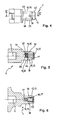
FIG. 2 , but here together with a dash-dotted line indicated tool in the form of a socket wrench before plugging on the plug of the stripping section (the lines running inside the socket wrench are shown with double-dashed lines), - FIG. 4
- the same output part in a second, rotated by 90 ° side view according to arrow IV in
FIG. 1 . - FIG. 5
- the same output part in a first longitudinal section along the section line VV in
FIG. 2 and - FIG. 6
- the same stripping section in a second, with respect to the
FIG. 5 90 ° rotated longitudinal section according to the section line VI-VI inFIG. 4 ,
Das aus der Zeichnung hervorgehende Abtriebsteil 1 wird drehfest mit der Abtriebswelle einer nicht dargestellten Handwerkzeugmaschine verbunden, so dass es koaxial zur Abtriebswelle angeordnet ist und das vordere Ende des Abtriebsstranges bildet. Beim Betrieb rotiert das Abtriebsteil 1 zusammen mit der Abtriebswelle um die Rotationsachslinie 2.The resulting from the
An das Abtriebsteil 1 kann wahlweise ein Werkzeug 3 mit einem Mehrkantschaft 4, insbesondere in Gestalt eines Bits, beispielsweise ein Schraubendreherbit, oder ein Werkzeug 5 mit einer Mehrkantaufnahme 6, insbesondere ein Steckschlüssel, lösbar in axialer Richtung angesteckt werden. Die beiden Werkzeuge 3, 5 sind im vom Abtriebsteil 1 entfernten Zustand gezeigt. Das Anstecken erfolgt in axialer Richtung von vorne her in Richtung des jeweils eingezeichneten Pfeils. Im angesteckten Zustand steht das jeweilige Werkzeug 3, 5 über eine Mehrkantanordnung in Rotationsmitnahmeeingriff mit dem Abtriebsteil 1.Optionally, a tool 3 with a polygonal shaft 4, in particular in the form of a bit, for example a screwdriver bit, or a
Das im dargestellten Falle von einem Bit gebildete Werkzeug 3 weist anschließend an den Mehrkantschaft 4 einen im angesteckten Zustand vor das Abtriebsteil 1 vorstehenden Funktionsabschnitt 7 auf, dessen vorderes Ende an die jeweils ein- oder auszudrehende Schraube angepasst ist, so dass der Funktionsabschnitt 7 in Rotationsmitnahmeeingriff mit der Schraube gebracht werden kann.The tool 3 formed in the illustrated case of one bit then has to the polygonal shaft 4 in the infected state before the
Das andere Werkzeug 5 weist, wird es von einem Steckschlüssel gebildet, anschließend an seine die Mehrkantaufnahme 6 enthaltende Partie 8 eine hülsenförmige Partie 9 mit einer von der der Mehrkantaufnahme 6 entgegengesetzten Stirnseite ausgehenden, mehrkantigen Steckschlüsselausnehmung auf, die auf den Mehrkantkopf einer Schraube oder auf eine Mutter Rotationsmitnahme fest aufgesteckt werden kann, so dass die Schraube bzw. die Mutter festgezogen oder gelöst werden kann.The
Anstelle eines Werkzeugs kann auch ein entsprechend angepasster Werkzeughalter (nicht dargestellt) an das Abtriebsteil 1 angesteckt werden, der seinerseits zum Halten eines Werkzeugs dient.Instead of a tool, a correspondingly adapted tool holder (not shown) can be connected to the
Das Abtriebsteil 1 weist eine von seiner Stirnseite 11 ausgehende Steckausnehmung 12 zum Einstecken des Mehrkantschaftes 4 des Werkzeugs 3 auf. Dabei ist die Steckausnehmung 12 mindestens über einen Teil ihrer Länge als Mehrkantausnehmung 13 ausgebildet, die im Querschnitt an den Werkzeug-Mehrkantschaft 4 angepasst ist, so dass im eingesteckten Zustand eine rotationsmitnahmefeste Verbindung besteht.The driven
Das Abtriebsteil 1 bildet ferner einen zur Steckausnehmung 12 koaxialen Steckzapfen 14, der mindestens über einen Teil seiner Länge als Mehrkantzapfen 15 ausgebildet ist. Auf den Steckzapfen 14 kann das andere Werkzeug 5 mit seiner Mehrkantaufnahme 6 aufgesteckt werden, deren Querschnitt an den Querschnitt des Mehrkantzapfens 15 angepasst ist.The driven
Somit kann das eine oder andere der Werkzeuge 3, 5 an das Abtriebsteil 1 angesteckt werden.Thus, one or the other of the
Die dem Werkzeug 3 zugeordnete Steckausnehmung 12 verläuft im Inneren des dem anderen Werkzeug 5 zugeordneten Steckzapfens 14.The plug-in recess 12 assigned to the tool 3 runs in the interior of the plug-in
An der Wandung der Steckausnehmung 12 sind federnde Rastmittel 16 angeordnet, die etwas in die Mehrkantausnehmung 13 vorstehen und zum lösbaren Verrasten des eingesteckten Mehrkantschaftes 4 des Werkzeugs 3 dienen. Bei dem federnden Rastmittel 16 handelt es sich um einen in eine Ringnut an der Wandung der Steckausnehmung 12 eingesetzten, geschlitzten Federring 17. In
Anstelle des federnden Rastmittels 16 könnte es sich auch um federnd gelagerte Rastmittel handeln, beispielsweise in Gestalt von mindestens einer in radialer Richtung federnd am Steckzapfen 14 gelagerten Rastkugel (nicht dargestellt).Instead of the resilient latching means 16, it could also be spring-mounted locking means, for example in the form of at least one resiliently mounted in the radial direction on the
Damit auch das aufgesteckte Werkzeug 5 sicher auf dem Steckzapfen-14 hält, ist am Steckzapfen 14 mindestens ein federndes oder federnd gelagertes, am Umfang des Steckzapfens 14 vorstehendes Rastelement 19 angeordnet, das mit dem Werkzeug 5 in lösbaren Verrastungseingriff gelangt. Im dargestellten Falle ist ein einziges Rastelement 19 in Gestalt einer Rastkugel 20 vorhanden, die durch eine Schraubenfeder 21 nach außen hin beaufschlagt ist. Die Schraubenfeder 21 und die Rastkugel 20 sind in einer Querbohrung 22 des Steckzapfens 14 angeordnet, die als Sackbohrung ausgebildet ist. Die Schraubenfeder 21 stützt sich einerseits am Boden der Querbohrung 22 und andererseits an der Rastkugel 20 ab. Die äußere Mündung der Querbohrung 22 ist etwas verjüngt, so dass die Rastkugel 20 in der Querbohrung 22 zurückgehalten wird. Die Rastkugel 20 befindet sich am als Mehrkantzapfen 15 ausgebildeten Bereich des Steckzapfens 14 und dabei an einer der Flachseiten des Mehrkantzapfens 15.Thus, the
Der Rastkugel 20 ist eine Rastausnehmung 23 an der Umfangsfläche der Mehrkantaufnahme 6 des Werkzeugs 5 zugeordnet. Die Rastausnehmung 23 kann beispielsweise von einer umlaufenden Rastnut 24 gebildet werden, so dass beim Aufstecken des Werkzeugs 5 nicht auf dessen Drehlage relativ zum Steckzapfen 14 geachtet werden muss. Beim Aufstecken wird die Rastkugel 20 zunächst von der Stirnseite des Werkzeugs 3 nach radial innen verdrängt. Gelangt die Rastausnehmung 23 zur Rastkugel 20, schnappt die Rastkugel 20 unter der Kraft der Schraubenfeder 21 nach außen in die Rastausnehmung 23, wodurch ein axialer Zusammenhalt erreicht wird.The detent ball 20 is associated with a latching recess 23 on the peripheral surface of the polygonal receptacle 6 of the
Der Steckzapfen 14 weist einen von der Stirnseite 11 des Abtriebsteils ausgehenden Stirnbereich 25 mit zylindrischer Au-βengestalt auf, an den sich der als Mehrkantzapfen 15 ausgebildete Bereich des Steckzapfens 14 anschließt. Der zylindrische Stirnbereich 25 weist beim Ausführungsbeispiel eine kleineren Durchmesser als der Mehrkantzapfen 15 auf.The plug-in
Der Werkzeug-Mehrkantschaft 4 ist als Sechskantschaft ausgebildet. Die Mehrkantausnehmung 13 weist einen zur Aufnahme eines solchen Mehrkantschaftes passenden Querschnitt auf.The tool polygonal shaft 4 is formed as a hex shank. The polygonal recess 13 has a suitable cross section for receiving such a polygonal shaft.
Der Mehrkantzapfen 15 ist in üblicher Weise ein Vierkantzapfen. Dementsprechend handelt es sich bei der Aufnahme 6 des Werkzeugs 5 um eine Vierkant-Mehrkantaufnahme. Der Mehrkantzapfen 15 bildet daher vier Flachseiten 26, 27, 28, 29.The polygonal pin 15 is a square pin in the usual way. Accordingly, it is in the recording 6 of the
Eine weitere zweckmäßige Maßnahme besteht darin, dass an mindestens einer Flachseite 26, 27, 28, 29 des Mehrkantzapfens 15, beim Ausführungsbeispiel an allen Flachseiten, eine Vertiefung zum lösbaren Einrasten eines aufgesteckten Werkzeughalters angeordnet ist.Another expedient measure is that on at least one
Claims (13)
Applications Claiming Priority (1)
| Application Number | Priority Date | Filing Date | Title |
|---|---|---|---|
| DE200610061757 DE102006061757A1 (en) | 2006-12-28 | 2006-12-28 | Stripping part on a hand tool |
Publications (2)
| Publication Number | Publication Date |
|---|---|
| EP1938927A2 true EP1938927A2 (en) | 2008-07-02 |
| EP1938927A3 EP1938927A3 (en) | 2010-02-17 |
Family
ID=39166372
Family Applications (1)
| Application Number | Title | Priority Date | Filing Date |
|---|---|---|---|
| EP07021234A Withdrawn EP1938927A3 (en) | 2006-12-28 | 2007-10-31 | Output part of a hand tool |
Country Status (2)
| Country | Link |
|---|---|
| EP (1) | EP1938927A3 (en) |
| DE (1) | DE102006061757A1 (en) |
Cited By (6)
| Publication number | Priority date | Publication date | Assignee | Title |
|---|---|---|---|---|
| WO2011104109A1 (en) * | 2010-02-25 | 2011-09-01 | Robert Bosch Gmbh | Handheld machine tool |
| WO2011104105A1 (en) * | 2010-02-25 | 2011-09-01 | Robert Bosch Gmbh | Handheld machine tool |
| WO2011154230A1 (en) * | 2010-06-09 | 2011-12-15 | Robert Bosch Gmbh | Portable machine tool comprising a tool fitting |
| CN113825594A (en) * | 2019-06-06 | 2021-12-21 | Wto资产管理有限公司 | Operating key for stationary and driven tool holders |
| SE2030350A1 (en) * | 2020-12-01 | 2022-06-02 | Atlas Copco Ind Technique Ab | Torque transferring device for use with a power tool |
| US11969861B2 (en) | 2020-12-01 | 2024-04-30 | Atlas Copco Industrial Technique Ab | Torque transferring device for use with a power tool |
Families Citing this family (1)
| Publication number | Priority date | Publication date | Assignee | Title |
|---|---|---|---|---|
| DE102022100891A1 (en) | 2022-01-17 | 2023-07-20 | Wera Werkzeuge Gmbh | Screwing tool for nuts and bits |
Citations (2)
| Publication number | Priority date | Publication date | Assignee | Title |
|---|---|---|---|---|
| US6363819B1 (en) * | 2000-09-13 | 2002-04-02 | Hung Yu Industrial Co., Ltd. | Knockdown hand tool structure |
| DE202005015031U1 (en) * | 2005-09-22 | 2006-04-27 | Chen, Chang-Ying, Ta Li | Multi-purpose hand tool has a handle with a hollow core terminating at the in a socket with a surrounding thread for a locknut |
-
2006
- 2006-12-28 DE DE200610061757 patent/DE102006061757A1/en not_active Withdrawn
-
2007
- 2007-10-31 EP EP07021234A patent/EP1938927A3/en not_active Withdrawn
Patent Citations (2)
| Publication number | Priority date | Publication date | Assignee | Title |
|---|---|---|---|---|
| US6363819B1 (en) * | 2000-09-13 | 2002-04-02 | Hung Yu Industrial Co., Ltd. | Knockdown hand tool structure |
| DE202005015031U1 (en) * | 2005-09-22 | 2006-04-27 | Chen, Chang-Ying, Ta Li | Multi-purpose hand tool has a handle with a hollow core terminating at the in a socket with a surrounding thread for a locknut |
Cited By (11)
| Publication number | Priority date | Publication date | Assignee | Title |
|---|---|---|---|---|
| WO2011104109A1 (en) * | 2010-02-25 | 2011-09-01 | Robert Bosch Gmbh | Handheld machine tool |
| WO2011104105A1 (en) * | 2010-02-25 | 2011-09-01 | Robert Bosch Gmbh | Handheld machine tool |
| CN102762327A (en) * | 2010-02-25 | 2012-10-31 | 罗伯特·博世有限公司 | Handheld machine tool |
| CN102762327B (en) * | 2010-02-25 | 2016-07-06 | 罗伯特·博世有限公司 | Hand held power machine |
| WO2011154230A1 (en) * | 2010-06-09 | 2011-12-15 | Robert Bosch Gmbh | Portable machine tool comprising a tool fitting |
| US9718173B2 (en) | 2010-06-09 | 2017-08-01 | Robert Bosch Gmbh | Handheld machine tool having a tool holding fixture |
| CN113825594A (en) * | 2019-06-06 | 2021-12-21 | Wto资产管理有限公司 | Operating key for stationary and driven tool holders |
| CN113825594B (en) * | 2019-06-06 | 2023-05-16 | Wto资产管理有限公司 | Operating key for stationary and driven tool holders |
| SE2030350A1 (en) * | 2020-12-01 | 2022-06-02 | Atlas Copco Ind Technique Ab | Torque transferring device for use with a power tool |
| SE545106C2 (en) * | 2020-12-01 | 2023-04-04 | Atlas Copco Ind Technique Ab | Torque transferring device for use with a power tool |
| US11969861B2 (en) | 2020-12-01 | 2024-04-30 | Atlas Copco Industrial Technique Ab | Torque transferring device for use with a power tool |
Also Published As
| Publication number | Publication date |
|---|---|
| EP1938927A3 (en) | 2010-02-17 |
| DE102006061757A1 (en) | 2008-07-03 |
Similar Documents
| Publication | Publication Date | Title |
|---|---|---|
| EP2262601B1 (en) | Hand-held machine tool | |
| DE102010055429A1 (en) | Bayonet clutch for rotary quick change-cutting tool arrangement, has transverse groove diametrically formed by cylindrical section, where opposite partial inner sides of respective walls are back-cut towards bottom surface of groove | |
| EP3261805A1 (en) | Hand-held power tool | |
| EP2188094B1 (en) | Hand power tool with a tool holder | |
| EP2771151A1 (en) | Portable power tool | |
| EP1938927A2 (en) | Output part of a hand tool | |
| EP1944838A1 (en) | Tool for tightening or loosening cable screws | |
| EP1819470B1 (en) | Hand-held machine tool, particularly drill or nut runner | |
| WO2001089770A1 (en) | Receiving head for a tool comprising a slit or polygonal actuating tip | |
| EP2423553A2 (en) | Hose clip with a tensioning screw, tensioning screw and tool for driving the tensioning screw | |
| DE102007003985A1 (en) | Sliding sleeve for attachment to the shaft of a screwdriver tool | |
| EP1262266A1 (en) | Gripping device | |
| DE102020107326B4 (en) | Extendable wrench | |
| DE102004028981B4 (en) | Torque-adjustable tool | |
| DE19920544C2 (en) | Joint for a tool | |
| EP2345496A1 (en) | Tool holder | |
| DE3507684A1 (en) | Clamping device for hand-operated machine tools | |
| DE3807439A1 (en) | Device which can be used as a wrench for breaking open a screw nut | |
| DE202005009372U1 (en) | Front of electrically operated screw driver, comprising clamping elements supported by elastic ring | |
| DE102004011579B4 (en) | Chuck for tool inserts | |
| DE3616731C2 (en) | ||
| DE102011009722A1 (en) | Adaptor element for connecting tool attachment with gripping portion of e.g. socket wrench utilized to release screw connection, has fastening region for connecting portion with element, where region has oval external peripheral contour | |
| DE3938244A1 (en) | Quick-change tool adaptor - is for portable drill or screwdriver and has drill fitted in adaptor with shank end entering quick-change chuck | |
| DE102004001580B3 (en) | Coupling device securing polishing disc to rotary machine tool has fixing part associated with polishing disc screwed to fixing part associated with machine tool drive | |
| DE10308056A1 (en) | Special tool for locking bolt connections around a screw axis, has holder twisted to be fastened with first part of bolt connection, and ratchet twisted over wrench socket to lock second part of bolt connection to its first part |
Legal Events
| Date | Code | Title | Description |
|---|---|---|---|
| PUAI | Public reference made under article 153(3) epc to a published international application that has entered the european phase |
Free format text: ORIGINAL CODE: 0009012 |
|
| AK | Designated contracting states |
Kind code of ref document: A2 Designated state(s): AT BE BG CH CY CZ DE DK EE ES FI FR GB GR HU IE IS IT LI LT LU LV MC MT NL PL PT RO SE SI SK TR |
|
| AX | Request for extension of the european patent |
Extension state: AL BA HR MK RS |
|
| PUAL | Search report despatched |
Free format text: ORIGINAL CODE: 0009013 |
|
| AK | Designated contracting states |
Kind code of ref document: A3 Designated state(s): AT BE BG CH CY CZ DE DK EE ES FI FR GB GR HU IE IS IT LI LT LU LV MC MT NL PL PT RO SE SI SK TR |
|
| AX | Request for extension of the european patent |
Extension state: AL BA HR MK RS |
|
| AKY | No designation fees paid | ||
| STAA | Information on the status of an ep patent application or granted ep patent |
Free format text: STATUS: THE APPLICATION IS DEEMED TO BE WITHDRAWN |
|
| 18D | Application deemed to be withdrawn |
Effective date: 20100818 |
|
| REG | Reference to a national code |
Ref country code: DE Ref legal event code: R108 Effective date: 20110201 Ref country code: DE Ref legal event code: 8566 |