EP1936352B1 - Blutzellenanalysegerät, Blutzellenanalyseverfahren und Computerprogramm - Google Patents
Blutzellenanalysegerät, Blutzellenanalyseverfahren und Computerprogramm Download PDFInfo
- Publication number
- EP1936352B1 EP1936352B1 EP07024306.8A EP07024306A EP1936352B1 EP 1936352 B1 EP1936352 B1 EP 1936352B1 EP 07024306 A EP07024306 A EP 07024306A EP 1936352 B1 EP1936352 B1 EP 1936352B1
- Authority
- EP
- European Patent Office
- Prior art keywords
- blood cells
- red blood
- light intensity
- scattered light
- sample
- Prior art date
- Legal status (The legal status is an assumption and is not a legal conclusion. Google has not performed a legal analysis and makes no representation as to the accuracy of the status listed.)
- Not-in-force
Links
Images


Classifications
-
- G—PHYSICS
- G01—MEASURING; TESTING
- G01N—INVESTIGATING OR ANALYSING MATERIALS BY DETERMINING THEIR CHEMICAL OR PHYSICAL PROPERTIES
- G01N15/00—Investigating characteristics of particles; Investigating permeability, pore-volume or surface-area of porous materials
- G01N15/10—Investigating individual particles
- G01N15/1031—Investigating individual particles by measuring electrical or magnetic effects
- G01N15/12—Investigating individual particles by measuring electrical or magnetic effects by observing changes in resistance or impedance across apertures when traversed by individual particles, e.g. by using the Coulter principle
-
- G—PHYSICS
- G01—MEASURING; TESTING
- G01N—INVESTIGATING OR ANALYSING MATERIALS BY DETERMINING THEIR CHEMICAL OR PHYSICAL PROPERTIES
- G01N15/00—Investigating characteristics of particles; Investigating permeability, pore-volume or surface-area of porous materials
- G01N15/10—Investigating individual particles
- G01N15/14—Optical investigation techniques, e.g. flow cytometry
- G01N15/1456—Optical investigation techniques, e.g. flow cytometry without spatial resolution of the texture or inner structure of the particle, e.g. processing of pulse signals
- G01N15/1459—Optical investigation techniques, e.g. flow cytometry without spatial resolution of the texture or inner structure of the particle, e.g. processing of pulse signals the analysis being performed on a sample stream
-
- G—PHYSICS
- G01—MEASURING; TESTING
- G01N—INVESTIGATING OR ANALYSING MATERIALS BY DETERMINING THEIR CHEMICAL OR PHYSICAL PROPERTIES
- G01N15/00—Investigating characteristics of particles; Investigating permeability, pore-volume or surface-area of porous materials
- G01N15/10—Investigating individual particles
- G01N15/14—Optical investigation techniques, e.g. flow cytometry
- G01N2015/1477—Multiparameters
-
- G—PHYSICS
- G01—MEASURING; TESTING
- G01N—INVESTIGATING OR ANALYSING MATERIALS BY DETERMINING THEIR CHEMICAL OR PHYSICAL PROPERTIES
- G01N15/00—Investigating characteristics of particles; Investigating permeability, pore-volume or surface-area of porous materials
- G01N15/10—Investigating individual particles
- G01N15/14—Optical investigation techniques, e.g. flow cytometry
- G01N2015/1486—Counting the particles
Definitions
- the present invention relates to a blood cell analyzer capable of measuring blood cells in a measurement sample, and outputting information useful for the diagnosis and treatment of blood diseases and the like, to a blood cell analyzing method, and to a computer program product thereof.
- Anemia is a blood condition in which there is a reduction in number of red blood cells, and the amount of hemoglobin contained in the red blood cells is also reduced.
- Anemia is generally screened on the basis of measurement results of items such as the red blood cell count (RBC), amount of hemoglobin (HGB), hematocrit value (HCT), mean cell volume (MCV), mean cell hemoglobin (MCH), mean cell hemoglobin concentration (MCHC) and the like obtained from a blood cell analyzer.
- RBC red blood cell count
- HGB amount of hemoglobin
- HCT hematocrit value
- MCV mean cell volume
- MHC mean cell hemoglobin
- MCHC mean cell hemoglobin concentration
- Iron deficiency anemia and ⁇ thalassemia are caused by blood disease. Both diseases are caused by impeded production of red blood cells, and exhibit low values for MCV and MCH. It is difficult to distinguish between iron deficiency anemia and P thalassemia because low hemoglobin is a characteristic of small cells. Furthermore, it is difficult to differentiate between mild (minor) cases of ⁇ thalassemia and iron deficiency anemia.
- U.S. patent No. 4,704,891 discloses methods and materials for calibrating flow cytometers and other analysis instruments using calibration particles, said calibration particles having known characteristics related to particles expected to be analyzed.
- EP 0 121 261 A2 discloses method and apparatus for distinguishing subclasses of leukocytes in a sample obtained from blood.
- U.S. patent No. 5,194,909 discloses an apparatus and method for measuring the volume and hemoglobin concentration of individual red blood cells in a whole blood sample.
- WO 02/29381 A2 discloses a method for analyzing an abnormal particle population in an experimental sample containing particles which involves analyzing a particle property distribution curve of the experimental sample in a particle analysis instrument.
- EP 0 949 498 A2 discloses an apparatus and method using flow cytometry for differentiating erythrocytes in urine to determine the origin and type of the erythrocytes.
- GB 2 173 004 A discloses a biological microparticle inspection apparatus for selectively counting specified biological microparticles such as blood corpuscles or cells of biological tissues.
- An object of the present invention is to provide information which is useful in the diagnosis and treatment of blood diseases and which is easily understandable and obtained at low cost by providing blood cell distribution information measured by several detection methods.
- a blood cell analyzer embodying features of the present invention includes: a first detection unit for electrically detecting blood cells in blood sample; a second detection unit for optically detecting blood cells in blood sample; a volume information obtainer for obtaining volume information of red blood cells based on the electrically detected blood cells by the first detection unit; a scattered light intensity information obtainer for obtaining a scattered light intensity of red blood cells based on the optically detected blood cells by the second detection unit; a display unit; and a data processor configured to prepare a first histogram of the volume information of each of the red blood cells obtained by the volume information obtainer, a second histogram of the scattered light intensity information of each of the red blood cells obtained by the scattered light intensity information obtainer and a screen for displaying on the display unit, the screen including the first and second histograms, the cell analyzer is further characterized in claim 1.
- a blood cell analyzing method embodying features of the present invention includes steps of: electrically detecting blood cells in blood sample; optically detecting blood cells in blood sample; obtaining volume information of red blood cells based on the electrically detected blood cells; obtaining scattered light intensity information of red blood cells based on the detected optically blood cells; preparing a first histogram using as parameters the obtained volume information of each of the red blood cells; preparing a second histogram using as parameters the obtained scattered light intensity information of each of the red blood cells; and displaying a screen including the first and second histograms, and the method is further characterized in claim 5.
- a computer program product for enabling a computer to execute a method of analyzing blood cells in a biological sample includes: a computer readable medium; and software instructions, on the computer readable medium, for enabling the computer to perform predetermined operations comprising: electrically detecting blood cells in blood sample; optically detecting blood cells in blood sample; obtaining volume information of red blood cells based on the electrically detected blood cells; obtaining scattered light intensity information of red blood cells based on the detected optically blood cells; preparing a first histogram using as parameters the obtained volume information of each of the red blood cells; preparing a second histogram using as parameters the obtained scattered light intensity information of each of the red blood cells; and displaying a screen including the first and second histograms, the computer program is further characterized in claim 7.
- FIG. 1 is an external view of an example of a blood cell analyzer.
- This apparatus is configured as a multifunction automatic blood cell analyzer, which has functions to measure a blood sample contained in a sample container (blood collection tube), and output the measurement results to a display or the like.
- the analyzer classifies and counts mature blood cells such as white blood cells, red blood cells, platelets and the like, as well as immature blood cells.
- the blood cell analyzer 1 is configured by a measuring device 2 which is provided with a fluid processing unit for diluting blood in a sample with dilution fluid and reacting the blood with reagent, a detection unit for detecting particle signals of the prepared measurement sample, and a signal processing unit for processing the detected particle signals, the blood cell analyzer 1 is also provided with a data processing device 3 which processes and stores the data obtained by the measuring device 2 and outputs the measurement results.
- the blood cell analyzer 1 of the present embodiment is configured by the measuring device 2 and data processing device 3 which are separate devices, both may be integrated as a single apparatus.
- the measuring device 2 is provided with a display and operating unit 7.
- the data processing device 3 is provided with a data processing unit 301, display unit 302, and input unit 303.
- FIG. 2 is a block diagram of a fluid processing unit 81 (refer to FIG. 5 ).
- the blood that is, the sample, within the test tube is aspirated by set dosage pump (not shown in the drawing) and introduced to a sampling valve 91.
- Measurement samples are prepared by collecting fixed quantities of sample in the sampling valve 91, and mixing the collected fixed quantity samples 92a through 92f with reagents which are supplied fixed quantities of dilution fluid and reagents by dosage pumps 93a through 93f, in reaction chambers 95a through 95f.
- the fixed quantity sample 92f collected in the sampling valve 91 is supplied to the reaction chamber 95f together with a fixed quantity of dilution fluid supplied by a dosage pump 93f.
- a fixed quantity of stain is also supplied to the reaction chamber 95f by a dosage pump 94f.
- Measurement samples are prepared for four types of white blood cells (4DIFF) by combining the sample 92f, dilution fluid, and stain in the reaction chamber 95f.
- the fixed quantity sample 92e collected in the sampling valve 91 is supplied to the reaction chamber 95e together with a fixed quantity of dilute hemolytic agent supplied by the dosage pump 93e.
- a fixed quantity of stain is also supplied to the reaction chamber 95e by a dosage pump 94e.
- a measurement sample for nucleated red blood cells (NRBC) is prepared by combining the sample 92e, dilute hemolytic agent, and stain in the reaction chamber 95e.
- the fixed quantity sample 92d collected in the sampling valve 91 is supplied to the reaction chamber 95d together with a fixed quantity of dilution fluid supplied by the dosage pump 93d.
- a fixed quantity of stain is also supplied to the reaction chamber 95d by a dosage pump 94d.
- a measurement sample for reticulocytes (RET) is prepared by combining the sample 92d, dilution fluid, and stain in the reaction chamber 95d.
- the reagent kit "RET search II" which is manufactured by Sysmex Corporation is suitable for use as the dilution fluid and stain.
- the stain in this reagent kit contains ethylene glycol and polymethene dyestuff, and is capable of staining erythrocytes, reticulocytes, and platelets.
- the fixed quantity sample 92c collected in the sampling valve 91 is supplied to reaction chamber 95c together with a fixed quantity of dilute hemolytic agent supplied by the dosage pump 93c.
- a measurement sample for white blood cells and basophils (WBC/BASO) is prepared by combining the sample 92c and dilute hemolytic agent in the reaction chamber 95c.
- the fixed quantity sample 92a collected in the sampling valve 91 is supplied to the reaction chamber 95a together with a fixed quantity of dilution fluid supplied by the dosage pump 93a.
- a measurement sample for red blood cells and platelets (hereinafter referred to as "RBC sample”) is prepared by combining the sample 92a and dilution fluid in the reaction chamber 95a.
- the hemoglobin (HGB) measurement sample which is a mixture of the fixed quantity sample 92b collected by the sampling valve 91 and the fixed quantity dilute hemolytic agent supplied by the dosage pump 92b, is supplied to a hemoglobin detection unit 42.
- the hemoglobin detection unit 42 measures the absorption light of the hemoglobin (HGB) measurement sample.
- the NRBC sample in the reaction chamber 95e, the WBC/BASO sample in the reaction chamber 95c, the 4DIFF sample in the reaction chamber 95f, and the RET sample in the reaction chamber 95d are sequentially introduced to an optical type detection unit 43 by a dosage syringe 97.
- the block 94h is a means for supplying sheath liquid to the detection unit 43.
- the RBC sample in the reaction chamber 95a is introduced to an electrical resistance type detection unit 41 by a dosage syringe 96.
- the block 94g is a means for supplying sheath liquid to the detection unit 41.
- the detection unit 4 is provided with an electrical resistance type detection unit 41 for measuring red blood cells, s hemoglobin detection unit 42 for detection the amount of hemoglobin in blood cells, and an optical type detection unit 43 for detecting white blood cells and reticulocytes.
- the detection units 41 and 43 are described in detail below.
- FIG. 3 shows an example of the electrical resistance type detection unit 41 using a sheath flow.
- the RBC sample containing red blood cells is extracted from a nozzle 101 at a constant speed by a dosage syringe 96 and encapsulated by a surrounding front sheath liquid 102 before passing through an orifice 103.
- the measurement sample is collected together with a back sheath 104 in a recovery tube 105.
- Electrodes (not shown in the drawing) are disposed so as to have the orifice 103 interposed therebetween, and the peak values of particle signals, which are proportional to the volume of the particle, are detected for each particle flowing through the orifice 103.
- FIG. 4 shows the detection unit 43 for optically measuring particles.
- the measurement samples prepared in the reaction chambers 95e, 95c, 95f, and 95d are extracted from nozzles at constant speed by a dosage syringe 47 and encapsulated by a surrounding sheath liquid before flowing through the orifice of the sheath flow cell 403.
- a laser beam emitted from a laser diode 401 irradiates the orifice area of the sheath flow cell 403 through a collimator lens 402.
- the forward scattered light from blood cells passing through the region of the orifice irradiated by the laser beam enter a photodiode 406 through a collective lens 404 which is provided with a beam stopper, and a pin hole plate 405.
- the side scattered light enters the a photomultiplier tube (hereinafter referred to as "photomultiplier") 412 through a collective lens 407 and a dichroic mirror 408, and the side fluorescent light enters an optical filter 409 via the dichroic mirror 408, then enters a photomultiplier 411 through a pinhole plate 410.
- photomultiplier a photomultiplier tube
- the forward scattered light signal from the photodiode 406 is subjected to various types of signal processing by a detection circuit 51, and thereafter send to a digital signal processing unit 6.
- the side scattered light signal from the photomultiplier 412 is subjected to various types of signal processing by a detection circuit 53, and thereafter sent to the digital signal processing unit 6.
- the side fluorescent light signal from the photomultiplier 411 is subjected to various types of signal processing by a detection circuit 52, and thereafter sent to the digital signal processing unit 6.
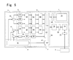
- FIG. 5 shows an example of a block diagram of the measuring device 2 of the analyzer.
- the particle signals detected by the detection unit 4 are subjected to signal processing by a signal processing unit 5 which performs analog signal processing, and subjected to data processing and analysis by a digital signal processing unit 6 which performs digital signal processing, then the resulting signals are sent to a data processing device 3 which displays and stores the results.
- a mechanism and fluid unit 8 is provided with a fluid processing unit 81.
- the operation and display unit 7, which is provided in the measuring device 2, is provided with a touch panel type liquid crystal panel 71.
- the forward scattered light signals, side scattered light signals, and side fluorescent light signals from the optical type detection unit 43 are detected and amplified by the respective detection circuits 51, 53, and 52.
- the signals from the electrical resistance type detection unit 41 are input to a detection circuit 54 and subj ected to red blood cell signal processing and platelet signal processing, and respectively output.
- the signals from the hemoglobin detection unit 42 are detected and amplified by a detection circuit 55.
- the signals from the detection circuits 51 through 54 are respectively subjected to waveform processing in waveform processing circuits 56 and 57 to eliminate noise and facilitate signal processing.
- the signals from the detection circuit 55 pass through a conversion circuit 58, and hemoglobin concentration data are determined by a counting circuit 63.
- each particle signal is sequentially subjected to A/D conversion by A/D conversion circuits 61 and 62, and the A/D converted data are input to the distribution data generating units 64 and 65 and stored therein, and the final particle distribution data are generated.
- a control processor 72 obtains the distribution data through an interface 66 and a bus 68, and the data are then sent to an analysis processor 74 through an interface 73.
- the analysis processor 74 analyzes clustering and the like in the distribution data.
- the analysis results are sent to an external data processing device 3 through an interface 75, and the data processing device 3 executes processes for screen display and storage of the data.
- the methods for performing particle analysis of the target red blood cells and providing information useful for the diagnosis and treatment of anemia are described below.
- Primary distribution data generated using as parameters the volume information obtained by measuring the RBC sample in the sheath flow electrical resistance type detection unit, and secondary distribution data (scattergram data) generating using as parameters the forward scattered light intensity and side fluorescent light intensity obtained by measuring the RET sample in the optical type detection unit are used.
- New information is obtained by analyzing the distribution data in the analysis processor.
- FIG. 6 is a red blood cell histogram (RBC histogram) measured from the RBC sample
- FIG. 7 is a histogram displaying demarcation lines M1 and M2 in the histogram of FIG. 6 .
- the horizontal axis of the histograms of FIGS. 6 and 7 (RBC histogram) is volume information (fL), and the vertical axis is the relative number (%).
- FIG. 10 is a flow chart of the analysis process.
- the analysis processor 74 generates an RBC histogram shown in FIG. 6 when the distribution data obtained from the RBC sample is received from the distribution data generating unit 65 (step S11).
- the analysis processor 74 reads and displays the demarcation line (threshold value) M1 set for the small region and the demarcation line (threshold value) M2 set for the large region of the RBC histogram shown in FIG. 7 from memory (step S12).
- the demarcation line M1 is a value equivalent to 70 fL
- the demarcation line M2 is a value equivalent to 110 fL.
- the analysis processor 74 calculates the percentage (MicroR) of red blood cells in the region below the demarcation line M1 relative to the total number f red blood cells in the RBC histogram, and calculates the percentage (MacroR) of red blood cells in the region above the demarcation line M2 relative to the total number of red blood cells (step S13).
- the analysis processor 74 displays a display screen that includes the RBC histogram which uses the volume of red blood cells as a parameter, and the MicroR and MacroR on the display unit of the data processing unit (step S14).
- FIG. 8 shows a scattergram obtained by measuring the RET sample (the vertical axis denotes forward scattered light intensity, and the horizontal axis denotes side fluorescent light intensity), and FIG. 9 shows a histogram obtained from the mature red blood cells Rb in the scattergram of FIG. 8 (the vertical axis denotes relative number, and the horizontal axis denotes forward scattered light intensity).
- FIG. 11 is a flow chart of the analysis process.
- Rb refers to mature the red blood cell distribution
- Re refers to the reticulocyte distribution
- Pt refers to platelet distribution.
- the analysis processor 74 generates the scattergram shown in FIG. 8 when distribution data obtained from the RET sample are received from the distribution generating unit 64 (step S21).
- the analysis processor 74 executes clustering analysis of the distribution data received from the distribution data generating unit 64 based on the scattered light intensity and fluorescent light intensity, and identifies the particles related to mature red blood cells Rb (step S22).
- the analysis processor 74 then generates a histogram using as parameters the forward scattered light of each particle identified as a mature red blood cell Rb (referred to as "RBC-Y histogram below”) (step S23).
- the analysis processor 74 reads from memory and displays the demarcation line (threshold value) L1 set for the small region, and the demarcation line (threshold value) L2 set for the large region of the RBC-Y histogram shown in FIG. 9 .
- the scattered light intensity of the red blood cells is a parameter which reflects the amount of hemoglobin contained in the red blood cells
- the demarcation line L1 is a scattered light intensity which is equivalent to 27 pg of hemoglobin
- the demarcation line L2 is a scattered light intensity which is equivalent to 33 pg of hemoglobin.
- the analysis processor 74 calculates the percentage of red blood cells (LScRBC) in the region below the demarcation line L1 relative to the total number of red blood cells, and calculates the percentage of red blood cells (HScRBC) in the region above the demarcation line L2 in the RBC-Y histogram (step S25).
- the analysis processor 74 displays a display screen which includes the RBC-Y histogram generated using the forward scattered light intensity of red blood cells as a parameter, the LScRBC, and the HScRBC on the display unit of the data processing unit 2. Furthermore, the analysis processor 74 displays the RBC histogram side by side with the RBC-Y histogram on the display screen.
- FIG. 12 shows an example of a display screen 200.
- An attribute display region 201 for displaying sample or patient attributes is provided at the top of the screen 200, and specifically, the sample number, patient name, sex, date of birth, ward, attending physician, date of measurement, time of measurement, comment and the like are displayed therein.
- a measurement result display region for displaying the results of a measurement is provided at the bottom of the attribute display region 201.
- Reference number 202 refers to tabs for switching the display content of the measurement result display region; there are a plurality of tabs which correspond to various items such as main menu, graph screen and the like.
- FIG. 12 shows the condition when the research (RBC related) tab is selected.
- a text display region for displaying numerical values and flags is provided in the left half of the measurement result display region, and a distribution map display region for displaying distribution maps is provided on the right half.
- a display region 203 for displaying the results of measurement items such as RBC, HGB, HCT, HFR and the like
- a display region 204 for displaying flagging results related to RBC or RET and a display region 205 for displaying research items such as RBC-O, RET-He, RBC-He, NRBC% and the like.
- a display region 76 is also provided for displaying the values of the four items of LScRBC, HScRBC, MicroR, and MacroR among the research items in the display region 205.
- the five distribution maps include an RET sample scattergram 77 in which the vertical axis denotes forward scattered light intensity and the horizontal axis denotes the side fluorescent light intensity, a scattergram 206 in which the scale of the horizontal axis of the scattergram 77 is changed in the display, an NRB sample scattergram 207 in which the vertical axis denotes the forward scattered light intensity and the horizontal axis denotes the side fluorescent light intensity, an RBC histogram 78, and an RBC-Y histogram 79.
- the RBC histogram, 78 and the RBC-Y histogram 79 are displayed side by side.
- Differences in the distributions of the histograms can be readily understood since the RBC histogram 78 and the RBC-Y histogram 79 are displayed side by side.
- the demarcation lines M1 and M2 may be displayed in the RBC histogram 78, and the demarcation lines L1 and L2 may be respectively displayed in the RBC-Y histogram 79.
- differences in the distribution patterns can be readily understood by displaying the demarcation lines in the distribution maps.
- the demarcation lines L1 and L2 are displayed in the RBC-Y histogram.
- the scattered light intensity which is used as a parameter for the RBC-Y histogram is information that reflects the size of the red blood cell, and also reflects the hemoglobin concentration in the red blood cell since it is measured optically.
- the RBC histogram uses the red blood cell volume as a parameter.
- ⁇ thalassemia characteristically has a low value for MicroR and a high value for LScRBC. Therefore, a physician can readily understand that a patient has ⁇ thalassemia by displaying the RBC histogram and RBC-Y histogram side by side.
- iron deficiency anemia and ⁇ thalassemia can be differentiated using the four indices.
- three groups which include normal, iron deficiency anemia, and ⁇ thalassemia can be differentiated by performing multi group differentiation analysis of the four indices obtained from the measurement of the blood sample. That is, if one has, beforehand, the four indices information obtained by measuring a plurality of samples of normal blood, and blood of patients with iron deficiency anemia, and blood of patients with ⁇ thalassemia, then it is possible to determine to which group a blood sample belongs based on the indices obtained by measuring the blood sample. hardly understandable and useful information can be obtained by this differentiation analysis.
- the functions and structure related to analysis and output performed by the blood cell analyzer of the present embodiment has been described in terms of being provided to the blood cell analyzer beforehand, the same functions may also be realized by a computer program, such that the functions of the present embodiment can be realized in a conventional blood cell analyzer by installing the computer program in the conventional blood cell analyzer.
- a scattered light intensity histogram for mature red blood cells Rb generated from a scattergram obtained by measuring a RET sample is used as the RBC-Y histogram in the present embodiment, it is to be noted that a scattered light intensity histogram of reticulocytes Re and mature red blood cells Rb in the scattergram may also be used for the purpose.
- the blood cell analyzer of the present invention calculates and analyzes a plurality of distribution data for target blood cells obtained by different particle detection principles as described above, information useful for the diagnosis and treatment of diseases can be obtained at low cost by comparing the distribution maps. Moreover, easily understandable information can be effectively obtained by outputting the distribution maps in the same format, and outputting the distribution maps together with the indices related to the distributions.
Landscapes
- Chemical & Material Sciences (AREA)
- Dispersion Chemistry (AREA)
- Physics & Mathematics (AREA)
- Health & Medical Sciences (AREA)
- Life Sciences & Earth Sciences (AREA)
- Analytical Chemistry (AREA)
- Biochemistry (AREA)
- General Health & Medical Sciences (AREA)
- General Physics & Mathematics (AREA)
- Immunology (AREA)
- Pathology (AREA)
- Investigating Or Analysing Biological Materials (AREA)
- Investigating Or Analysing Materials By Optical Means (AREA)
- Investigating Or Analyzing Materials By The Use Of Electric Means (AREA)
Claims (8)
- Blutzell-Analysegerät (1), umfassend:eine erste Nachweiseinheit (41) zum elektrischen Nachweisen von Blutzellen in einer Blutprobe;eine zweite Nachweiseinheit (43) zum optischen Nachweisen von Blutzellen in einer Blutprobe;einen Volumeninformation-Erhaltungsteil ("volume information obtainer") (65) zum Erhalten von Volumeninformation(en) von roten Blutzellen, basierend auf den elektrisch nachgewiesenen Blutzellen von der ersten Nachweisheit;einen Streulichtintensitätsinformations-Erhaltungsteil ("scattered light intensity information obtainer") (64) zum Erhalten einer Streulichtintensität von roten Blutzellen, basierend auf den optisch nachgewiesenen Blutzellen von der zweiten Nachweiseinheit;eine Anzeigeeinheit (302); undeinen Datenprozessor (74), konfiguriert um ein erstes Histogramm der Volumeninformation(en) von jeder der roten Blutzellen, erhalten durch den Volumeninformations-Erhaltungsteil, ein zweites Histogramm der Streulichtintensitätsinformation(en) von jeder der roten Blutzellen, erhalten durch den Streulichtintensitätsinformations-Erhaltungsteil, und einen Bildschirm (200) zum Anzeigen auf der Anzeigeeinheit herzustellen, wobei der Bildschirm die ersten und zweiten Histogramme einschließt,dadurch gekennzeichnet, dass:das erste Histogramm erste und zweite Demarkationslinien enthält, die ersten und zweiten Schwellenwerten entsprechen, und das zweite Histogramm dritte und vierte Demarkationslinien enthält, die dritten und vierten Schwellenwerten entsprechen,wobei der Datenprozessor dazu konfiguriert ist, einen Prozentsatz von roten Blutzellen, welche Volumeninformation(en) besitzen, die weniger als der erste Schwellenwert ist/sind, relativ zu allen Blutzellen zu berechnen (MicroR), einen Prozentsatz von roten Blutzellen, welche Volumeninformation(en) besitzen, die größer als der zweite Schwellenwert ist/sind, relativ zu allen roten Blutzellen zu berechnen (MacroR), einen Prozentsatz von roten Blutzellen, welche Streulichtintensitätsinformation(en) besitzen, die weniger als der dritte Schwellenwert ist/sind, relativ zu allen roten Blutzellen zu berechnen (LScRBC), undeinen Prozentsatz von roten Blutzellen, welche Streulichtintensitätsinformation(en) besitzen, die größer als der vierte Schwellenwert ist/sind, relativ zu allen roten Blutzellen zu berechnen (HScRBC), undwobei der Datenprozessor den Bildschirm einschließlich der ersten und zweiten Histogramme, des berechneten MicroR, des berechneten MacroR, des berechneten LScRBC und des berechneten HScRBC herstellt.
- Blutzell-Analysegerät gemäß Anspruch 1, wobei der Datenprozessor den Bildschirm herstellt, so dass er die ersten und zweiten Histogramme Seite an Seite einschließt.
- Blutzell-Analysegerät gemäß Anspruch 1 oder 2, ferner umfassend eine Messproben-Herstellungseinheit (81) zum Herstellen einer ersten Messprobe aus vorbestimmten Mengen von Blutprobe und Verdünnungsmittel und Herstellen einer zweiten Messprobe aus vorbestimmten Mengen von Blutprobe und Verdünnungsmittel, sowie einen Farbstoff zum Färben von Retikulozyten, wobei die erste Nachweiseinheit Blutzellen in der ersten Messprobe nachweist und die zweite Nachweiseinheit Blutzellen in der zweiten Messprobe nachweist.
- Blutzell-Analysegerät gemäß Anspruch 3, wobei der Datenprozessor rote Blutzellen und Retikulozyten klassifiziert und der Streulichtintensitätsinformations-Erhaltungsteil Streulichtintensitätsinformation(en) von jeder klassifizierten roten Blutzelle, basierend auf Daten, die von jeder Blutzelle durch die zweite Nachweiseinheit erhalten wurden, erhält.
- Verfahren zum Analysieren von Blutzellen, umfassend die Schritte:elektrisches Nachweisen von Blutzellen in einer Blutprobe;optisches Naschweisen von Blutzellen in einer Blutprobe;Erhalten von Volumeninformation(en) von roten Blutzellen, basierend auf den elektrisch nachgewiesenen Blutzellen;Erhalten von Streulichtintensitätsinformation(en) von roten Blutzellen, basierend auf den optisch nachgewiesenen Blutzellen;Herstellen eines ersten Histogramms (78) mittels der erhaltenen Volumeninformation(en) von jeder der roten Blutzellen als Parameter;Herstellen eines zweiten Histogramms (79) mittels der erhaltenen Streulichtintensitätsinformation(en) von jeder der roten Blutzellen als Parameter; undAnzeigen eines Bildschirms einschließlich der ersten und zweiten Histogramme;dadurch gekennzeichnet, dass:das erste Histogramm erste und zweite Demarkationslinien enthält, die ersten und zweiten Schwellenwerten entsprechen, und das zweite Histogramm dritte und vierte Demarkationslinien enthält, die dritten und vierten Schwellenwerten entsprechen,und das Verfahren ferner umfasst:einen Schritt des Berechnens eines Prozentsatzes von roten Blutzellen, die Volumeninformation(en) besitzen, die weniger als der erste Schwellenwert ist/sind, relativ zu allen roten Blutzellen (MicroR), eines Prozentsatzes von roten Blutzellen, die Volumeninformation(en) besitzen, die größer als der zweite Schwellenwert ist/sind, relativ zu allen roten Blutzellen (MacroR), eines Prozentsatzes von roten Blutzellen, die Streulichtintensitätsinformation(en) besitzen, die weniger als der dritte Schwellenwert ist/sind, relativ zu allen roten Blutzellen (LScRBC), und eines Prozentsatzes von roten Blutzellen, die Streulichtintensitätsinformation(en) besitzen, die größer als der vierte Schwellenwert ist/sind, relativ zu allen roten Blutzellen (HScRBC),wobei der Schritt des Anzeigens durchgeführt wird, indem der Bildschirm einschließlich der ersten und zweiten Histogramme, des berechneten MicroR, des berechneten MacroR, des berechneten LScRBC und des berechneten HScRBC angezeigt wird.
- Verfahren gemäß Anspruch 5, wobei der Schritt des Anzeigens durchgeführt wird, indem der Bildschirm angezeigt wird, so dass er die ersten und zweiten Histogramme Seite an Seite einschließt.
- Computerprogramm-Erzeugnis, um einen Computer zu befähigen, ein Verfahren zum Analysieren von Blutzellen in einer biologischen Probe auszuführen, wobei das Computerprogramm-Erzeugnis umfasst:ein computerlesbares Medium; undSoftware-Anweisungen, auf dem computerlesbaren Medium, um den Computer dazu zu befähigen, vorbestimmte Operationen durchzuführen, umfassend:elektrisches Nachweisen von Blutzellen in einer Blutprobe;optisches Nachweisen von Blutzellen in einer Blutprobe;Erhalten von Volumeninformation(en) von roten Blutzellen, basierend auf den elektrisch nachgewiesenen Blutzellen;Erhalten von Streulichtintensitätsinformation(en) von roten Blutzellen, basierend auf den optisch nachgewiesenen Blutzellen;Herstellen eines ersten Histogramms mittels der erhaltenen Volumeninformation(en) von jeder der roten Blutzellen als Parameter;Herstellen eines zweiten Histogramms mittels der erhaltenen Streulichtintensitätsinformation(en) von jeder der roten Blutzellen als Parameter; undAnzeigen eines Bildschirms einschließlich der ersten und zweiten Histogramme,dadurch gekennzeichnet, dass:das erste Histogramm erste und zweite Demarkationslinien enthält, die ersten und zweiten Schwellenwerten entsprechen, und das zweite Histogramm dritte und vierte Demarkationslinien enthält, die dritten und vierten Schwellenwerten entsprechen,wobei die vorbestimmten Operationen umfassen:das Berechnen eines Prozentsatzes von roten Blutzellen, die Volumeninformation(en) besitzen, die weniger als der erste Schwellenwert ist/sind, relativ zu allen roten Blutzellen (MicroR), eines Prozentsatzes von roten Blutzellen, die Volumeninformation(en) besitzen, die größer als der zweite Schwellenwert ist/sind, relativ zu allen roten Blutzellen (MacroR), eines Prozentsatzes von roten Blutzellen, die Streulichtintensitätsinformation(en) besitzen, die weniger als der dritte Schwellenwert ist/sind, relativ zu allen roten Blutzellen (LScRBC), und eines Prozentsatzes von roten Blutzellen, die Streulichtintensitätsinformation(en) besitzen, die größer als der vierte Schwellenwert ist/sind, relativ zu allen roten Blutzellen (HScRBC),wobei die vorbestimmte Operation des Anzeigens durchgeführt wird, indem der Bildschirm einschließlich der ersten und zweiten Histogramme, des berechneten MicroR, des berechneten MacroR, des berechneten LScRBC und des berechneten HScRBC angezeigt wird.
- Computerprogramm-Erzeugnis gemäß Anspruch 7, wobei die vorbestimmte Operation des Anzeigens durchgeführt wird, indem der Bildschirm angezeigt wird, so dass er die ersten und zweiten Histogramme Seite an Seite einschließt.
Applications Claiming Priority (1)
| Application Number | Priority Date | Filing Date | Title |
|---|---|---|---|
| JP2006342228 | 2006-12-20 |
Publications (3)
| Publication Number | Publication Date |
|---|---|
| EP1936352A2 EP1936352A2 (de) | 2008-06-25 |
| EP1936352A3 EP1936352A3 (de) | 2013-02-27 |
| EP1936352B1 true EP1936352B1 (de) | 2015-08-12 |
Family
ID=39027451
Family Applications (1)
| Application Number | Title | Priority Date | Filing Date |
|---|---|---|---|
| EP07024306.8A Not-in-force EP1936352B1 (de) | 2006-12-20 | 2007-12-14 | Blutzellenanalysegerät, Blutzellenanalyseverfahren und Computerprogramm |
Country Status (4)
| Country | Link |
|---|---|
| US (1) | US8017078B2 (de) |
| EP (1) | EP1936352B1 (de) |
| JP (1) | JP5010443B2 (de) |
| CN (1) | CN101206218B (de) |
Families Citing this family (18)
| Publication number | Priority date | Publication date | Assignee | Title |
|---|---|---|---|---|
| US9322834B2 (en) * | 2007-05-30 | 2016-04-26 | Sysmex Corporation | Sample analyzer, blood analyzer and displaying method |
| JP5350611B2 (ja) * | 2007-06-28 | 2013-11-27 | シスメックス株式会社 | 表示方法および試料分析装置 |
| JP5530691B2 (ja) * | 2009-09-25 | 2014-06-25 | シスメックス株式会社 | 血球計数装置、診断支援装置、診断支援方法及びコンピュータプログラム |
| AU2012287304B2 (en) | 2011-07-22 | 2015-08-13 | Roche Diagnostics Hematology, Inc. | Identifying and measuring reticulocytes |
| CN103090886B (zh) * | 2011-10-31 | 2015-08-26 | 深圳迈瑞生物医疗电子股份有限公司 | 光信号的去噪方法和装置 |
| EP2939000A1 (de) | 2012-12-31 | 2015-11-04 | Beckman Coulter, Inc. | Systeme und verfahren zur zählung unreifer blutplättchen |
| JP6612050B2 (ja) | 2014-08-28 | 2019-11-27 | シスメックス株式会社 | 血液分析装置、診断支援方法、およびコンピュータプログラム |
| JP6370659B2 (ja) * | 2014-09-26 | 2018-08-08 | シスメックス株式会社 | 血液分析装置および血液分析方法 |
| US11536709B2 (en) | 2016-03-30 | 2022-12-27 | Siemens Healthcare Diagnostics Inc. | Systems, methods, and apparatus for processing, organizing, and displaying platelet cell data |
| US11226278B2 (en) | 2016-11-08 | 2022-01-18 | Kennesaw State University Research And Service Foundation, Inc. | Leukocyte quantitation microfluidic method and device |
| CN108169081B (zh) * | 2017-12-14 | 2021-06-04 | 四川大学华西医院 | 血细胞分析的差值核查方法及其应用方法 |
| CN108416767B (zh) * | 2018-02-09 | 2021-02-19 | 重庆东渝中能实业有限公司 | 基于全息成像的红细胞多项生理参数检测方法 |
| WO2020248138A1 (zh) * | 2019-06-11 | 2020-12-17 | 深圳迈瑞生物医疗电子股份有限公司 | 样本检测方法及样本分析仪 |
| JP7491703B2 (ja) * | 2020-02-05 | 2024-05-28 | 日本光電工業株式会社 | 粒子分析方法および粒子分析装置 |
| CN111542744B (zh) * | 2020-03-10 | 2024-03-15 | 深圳迈瑞生物医疗电子股份有限公司 | 血液分析仪、血液分析方法和计算机可读存储介质 |
| EP3905260A1 (de) * | 2020-04-28 | 2021-11-03 | Sysmex Corporation | Verfahren, vorrichtung und system zum testen von blut |
| CN114252384B (zh) * | 2021-12-02 | 2022-12-13 | 中元汇吉生物技术股份有限公司 | 网织红细胞计数方法、装置、系统与计算机可读存储介质 |
| CN114813706B (zh) * | 2022-06-29 | 2022-12-13 | 国科大杭州高等研究院 | 一种血细胞高光谱光镊捕获能量共振转移分析仪 |
Family Cites Families (19)
| Publication number | Priority date | Publication date | Assignee | Title |
|---|---|---|---|---|
| JPS5825144A (ja) * | 1981-08-07 | 1983-02-15 | 東亜医用電子株式会社 | 血液分析方法およびその装置 |
| JPS5858439A (ja) * | 1981-10-01 | 1983-04-07 | Toa Medical Electronics Co Ltd | 血小板計数装置 |
| JPS59184841A (ja) * | 1983-04-05 | 1984-10-20 | ベクトン・デイツキンソン・アンド・カンパニ− | サンプル中の白血球のサブクラスを識別する方法および装置 |
| US4735504A (en) * | 1983-10-31 | 1988-04-05 | Technicon Instruments Corporation | Method and apparatus for determining the volume & index of refraction of particles |
| JPS61225656A (ja) * | 1985-03-29 | 1986-10-07 | Toshiba Corp | 検体検査装置 |
| US4704891A (en) * | 1986-08-29 | 1987-11-10 | Becton, Dickinson And Company | Method and materials for calibrating flow cytometers and other analysis instruments |
| JP2674705B2 (ja) * | 1988-06-10 | 1997-11-12 | 東亜医用電子株式会社 | 一次元分布分画方法 |
| JP2815435B2 (ja) * | 1989-12-22 | 1998-10-27 | 株式会社日立製作所 | 粒子解析装置及び血球カウンタ |
| US5194909A (en) * | 1990-12-04 | 1993-03-16 | Tycko Daniel H | Apparatus and method for measuring volume and hemoglobin concentration of red blood cells |
| JP3232145B2 (ja) * | 1991-12-27 | 2001-11-26 | シスメックス株式会社 | 網赤血球測定方法 |
| US5844685A (en) * | 1996-07-30 | 1998-12-01 | Bayer Corporation | Reference laser beam sampling apparatus |
| JP3867880B2 (ja) * | 1998-04-08 | 2007-01-17 | シスメックス株式会社 | 尿中赤血球の鑑別装置および方法 |
| US6592822B1 (en) * | 1998-05-14 | 2003-07-15 | Luminex Corporation | Multi-analyte diagnostic system and computer implemented process for same |
| JPH11326315A (ja) * | 1998-05-21 | 1999-11-26 | Sysmex Corp | β−サラセミアの鑑別方法 |
| JP4101994B2 (ja) * | 1999-01-21 | 2008-06-18 | シスメックス株式会社 | 粒子分析装置および自動粒子分析方法 |
| US6535836B1 (en) * | 2000-09-29 | 2003-03-18 | Coulter International Corp. | Method for the analysis of abnormal particle populations |
| US6630990B2 (en) * | 2001-06-05 | 2003-10-07 | Abbott Laboratories | Optical method and apparatus for red blood cell differentiation on a cell-by-cell basis, and simultaneous analysis of white blood cell differentiation |
| JP4417143B2 (ja) * | 2004-03-11 | 2010-02-17 | シスメックス株式会社 | 試料分析装置、プログラムおよびそのプログラムを記録した記録媒体 |
| JP4679843B2 (ja) * | 2004-07-02 | 2011-05-11 | シスメックス株式会社 | 血液分析装置および分析プログラム |
-
2007
- 2007-11-28 JP JP2007308066A patent/JP5010443B2/ja active Active
- 2007-12-14 EP EP07024306.8A patent/EP1936352B1/de not_active Not-in-force
- 2007-12-18 CN CN2007103018327A patent/CN101206218B/zh not_active Expired - Fee Related
- 2007-12-19 US US12/002,973 patent/US8017078B2/en active Active
Also Published As
| Publication number | Publication date |
|---|---|
| US8017078B2 (en) | 2011-09-13 |
| CN101206218B (zh) | 2011-12-07 |
| CN101206218A (zh) | 2008-06-25 |
| US20080199947A1 (en) | 2008-08-21 |
| EP1936352A2 (de) | 2008-06-25 |
| JP2008175807A (ja) | 2008-07-31 |
| JP5010443B2 (ja) | 2012-08-29 |
| EP1936352A3 (de) | 2013-02-27 |
Similar Documents
| Publication | Publication Date | Title |
|---|---|---|
| EP1936352B1 (de) | Blutzellenanalysegerät, Blutzellenanalyseverfahren und Computerprogramm | |
| US7450223B2 (en) | Sample analyzer | |
| CN111542744B (zh) | 血液分析仪、血液分析方法和计算机可读存储介质 | |
| US8808623B2 (en) | Diagnosis assisting system, diagnosis assisting information providing device and computer program product | |
| JP4949898B2 (ja) | 血球分析装置 | |
| US11415575B2 (en) | Sample analyzer and computer program product | |
| US9453790B2 (en) | Blood analyzer, blood analyzing method, and computer program product | |
| JP4926812B2 (ja) | 血球分析装置および体液分析方法 | |
| EP3260842B1 (de) | Hämatologischer analysator und verfahren zur analyse einer probe | |
| CN101097180B (zh) | 分析仪及分析方法 | |
| US9939453B2 (en) | Immature platelet enumeration systems and methods | |
| JP4101994B2 (ja) | 粒子分析装置および自動粒子分析方法 | |
| CN114450589A (zh) | 分析血液样本中红细胞方法及血液分析系统 | |
| US20010053551A1 (en) | Method for quantitatively analyzing fragmented red blood cells | |
| Davis et al. | Automated cell analysis: principles | |
| JP4969596B2 (ja) | 試料分析装置、試料分析方法およびプログラム | |
| Kaznowska-Bystryk | The automated hematology analyzers |
Legal Events
| Date | Code | Title | Description |
|---|---|---|---|
| PUAI | Public reference made under article 153(3) epc to a published international application that has entered the european phase |
Free format text: ORIGINAL CODE: 0009012 |
|
| AK | Designated contracting states |
Kind code of ref document: A2 Designated state(s): AT BE BG CH CY CZ DE DK EE ES FI FR GB GR HU IE IS IT LI LT LU LV MC MT NL PL PT RO SE SI SK TR |
|
| AX | Request for extension of the european patent |
Extension state: AL BA HR MK RS |
|
| PUAL | Search report despatched |
Free format text: ORIGINAL CODE: 0009013 |
|
| AK | Designated contracting states |
Kind code of ref document: A3 Designated state(s): AT BE BG CH CY CZ DE DK EE ES FI FR GB GR HU IE IS IT LI LT LU LV MC MT NL PL PT RO SE SI SK TR |
|
| AX | Request for extension of the european patent |
Extension state: AL BA HR MK RS |
|
| RIC1 | Information provided on ipc code assigned before grant |
Ipc: G01N 15/14 20060101ALI20130123BHEP Ipc: G01N 15/12 20060101AFI20130123BHEP |
|
| 17P | Request for examination filed |
Effective date: 20130725 |
|
| RBV | Designated contracting states (corrected) |
Designated state(s): AT BE BG CH CY CZ DE DK EE ES FI FR GB GR HU IE IS IT LI LT LU LV MC MT NL PL PT RO SE SI SK TR |
|
| AKX | Designation fees paid |
Designated state(s): AT BE BG CH CY CZ DE DK EE ES FI FR GB GR HU IE IS IT LI LT LU LV MC MT NL PL PT RO SE SI SK TR |
|
| 17Q | First examination report despatched |
Effective date: 20140320 |
|
| GRAP | Despatch of communication of intention to grant a patent |
Free format text: ORIGINAL CODE: EPIDOSNIGR1 |
|
| INTG | Intention to grant announced |
Effective date: 20150311 |
|
| RIN1 | Information on inventor provided before grant (corrected) |
Inventor name: LINSSEN, JO Inventor name: KALKMAN, HANS |
|
| GRAS | Grant fee paid |
Free format text: ORIGINAL CODE: EPIDOSNIGR3 |
|
| GRAA | (expected) grant |
Free format text: ORIGINAL CODE: 0009210 |
|
| AK | Designated contracting states |
Kind code of ref document: B1 Designated state(s): AT BE BG CH CY CZ DE DK EE ES FI FR GB GR HU IE IS IT LI LT LU LV MC MT NL PL PT RO SE SI SK TR |
|
| REG | Reference to a national code |
Ref country code: GB Ref legal event code: FG4D |
|
| REG | Reference to a national code |
Ref country code: CH Ref legal event code: EP |
|
| REG | Reference to a national code |
Ref country code: AT Ref legal event code: REF Ref document number: 742599 Country of ref document: AT Kind code of ref document: T Effective date: 20150815 |
|
| REG | Reference to a national code |
Ref country code: IE Ref legal event code: FG4D |
|
| REG | Reference to a national code |
Ref country code: DE Ref legal event code: R096 Ref document number: 602007042505 Country of ref document: DE |
|
| REG | Reference to a national code |
Ref country code: LT Ref legal event code: MG4D |
|
| REG | Reference to a national code |
Ref country code: AT Ref legal event code: MK05 Ref document number: 742599 Country of ref document: AT Kind code of ref document: T Effective date: 20150812 |
|
| REG | Reference to a national code |
Ref country code: NL Ref legal event code: MP Effective date: 20150812 |
|
| PG25 | Lapsed in a contracting state [announced via postgrant information from national office to epo] |
Ref country code: FI Free format text: LAPSE BECAUSE OF FAILURE TO SUBMIT A TRANSLATION OF THE DESCRIPTION OR TO PAY THE FEE WITHIN THE PRESCRIBED TIME-LIMIT Effective date: 20150812 Ref country code: LV Free format text: LAPSE BECAUSE OF FAILURE TO SUBMIT A TRANSLATION OF THE DESCRIPTION OR TO PAY THE FEE WITHIN THE PRESCRIBED TIME-LIMIT Effective date: 20150812 Ref country code: GR Free format text: LAPSE BECAUSE OF FAILURE TO SUBMIT A TRANSLATION OF THE DESCRIPTION OR TO PAY THE FEE WITHIN THE PRESCRIBED TIME-LIMIT Effective date: 20151113 Ref country code: LT Free format text: LAPSE BECAUSE OF FAILURE TO SUBMIT A TRANSLATION OF THE DESCRIPTION OR TO PAY THE FEE WITHIN THE PRESCRIBED TIME-LIMIT Effective date: 20150812 |
|
| PG25 | Lapsed in a contracting state [announced via postgrant information from national office to epo] |
Ref country code: PT Free format text: LAPSE BECAUSE OF FAILURE TO SUBMIT A TRANSLATION OF THE DESCRIPTION OR TO PAY THE FEE WITHIN THE PRESCRIBED TIME-LIMIT Effective date: 20151214 Ref country code: ES Free format text: LAPSE BECAUSE OF FAILURE TO SUBMIT A TRANSLATION OF THE DESCRIPTION OR TO PAY THE FEE WITHIN THE PRESCRIBED TIME-LIMIT Effective date: 20150812 Ref country code: IS Free format text: LAPSE BECAUSE OF FAILURE TO SUBMIT A TRANSLATION OF THE DESCRIPTION OR TO PAY THE FEE WITHIN THE PRESCRIBED TIME-LIMIT Effective date: 20151212 Ref country code: SE Free format text: LAPSE BECAUSE OF FAILURE TO SUBMIT A TRANSLATION OF THE DESCRIPTION OR TO PAY THE FEE WITHIN THE PRESCRIBED TIME-LIMIT Effective date: 20150812 Ref country code: AT Free format text: LAPSE BECAUSE OF FAILURE TO SUBMIT A TRANSLATION OF THE DESCRIPTION OR TO PAY THE FEE WITHIN THE PRESCRIBED TIME-LIMIT Effective date: 20150812 Ref country code: PL Free format text: LAPSE BECAUSE OF FAILURE TO SUBMIT A TRANSLATION OF THE DESCRIPTION OR TO PAY THE FEE WITHIN THE PRESCRIBED TIME-LIMIT Effective date: 20150812 |
|
| PG25 | Lapsed in a contracting state [announced via postgrant information from national office to epo] |
Ref country code: NL Free format text: LAPSE BECAUSE OF FAILURE TO SUBMIT A TRANSLATION OF THE DESCRIPTION OR TO PAY THE FEE WITHIN THE PRESCRIBED TIME-LIMIT Effective date: 20150812 |
|
| PG25 | Lapsed in a contracting state [announced via postgrant information from national office to epo] |
Ref country code: IT Free format text: LAPSE BECAUSE OF FAILURE TO SUBMIT A TRANSLATION OF THE DESCRIPTION OR TO PAY THE FEE WITHIN THE PRESCRIBED TIME-LIMIT Effective date: 20150812 Ref country code: SK Free format text: LAPSE BECAUSE OF FAILURE TO SUBMIT A TRANSLATION OF THE DESCRIPTION OR TO PAY THE FEE WITHIN THE PRESCRIBED TIME-LIMIT Effective date: 20150812 Ref country code: DK Free format text: LAPSE BECAUSE OF FAILURE TO SUBMIT A TRANSLATION OF THE DESCRIPTION OR TO PAY THE FEE WITHIN THE PRESCRIBED TIME-LIMIT Effective date: 20150812 Ref country code: EE Free format text: LAPSE BECAUSE OF FAILURE TO SUBMIT A TRANSLATION OF THE DESCRIPTION OR TO PAY THE FEE WITHIN THE PRESCRIBED TIME-LIMIT Effective date: 20150812 Ref country code: CZ Free format text: LAPSE BECAUSE OF FAILURE TO SUBMIT A TRANSLATION OF THE DESCRIPTION OR TO PAY THE FEE WITHIN THE PRESCRIBED TIME-LIMIT Effective date: 20150812 |
|
| REG | Reference to a national code |
Ref country code: DE Ref legal event code: R097 Ref document number: 602007042505 Country of ref document: DE |
|
| PG25 | Lapsed in a contracting state [announced via postgrant information from national office to epo] |
Ref country code: RO Free format text: LAPSE BECAUSE OF FAILURE TO SUBMIT A TRANSLATION OF THE DESCRIPTION OR TO PAY THE FEE WITHIN THE PRESCRIBED TIME-LIMIT Effective date: 20150812 Ref country code: BE Free format text: LAPSE BECAUSE OF NON-PAYMENT OF DUE FEES Effective date: 20151231 |
|
| PLBE | No opposition filed within time limit |
Free format text: ORIGINAL CODE: 0009261 |
|
| STAA | Information on the status of an ep patent application or granted ep patent |
Free format text: STATUS: NO OPPOSITION FILED WITHIN TIME LIMIT |
|
| 26N | No opposition filed |
Effective date: 20160513 |
|
| PG25 | Lapsed in a contracting state [announced via postgrant information from national office to epo] |
Ref country code: LU Free format text: LAPSE BECAUSE OF FAILURE TO SUBMIT A TRANSLATION OF THE DESCRIPTION OR TO PAY THE FEE WITHIN THE PRESCRIBED TIME-LIMIT Effective date: 20151214 Ref country code: MC Free format text: LAPSE BECAUSE OF FAILURE TO SUBMIT A TRANSLATION OF THE DESCRIPTION OR TO PAY THE FEE WITHIN THE PRESCRIBED TIME-LIMIT Effective date: 20150812 |
|
| REG | Reference to a national code |
Ref country code: CH Ref legal event code: PL |
|
| GBPC | Gb: european patent ceased through non-payment of renewal fee |
Effective date: 20151214 |
|
| PG25 | Lapsed in a contracting state [announced via postgrant information from national office to epo] |
Ref country code: SI Free format text: LAPSE BECAUSE OF FAILURE TO SUBMIT A TRANSLATION OF THE DESCRIPTION OR TO PAY THE FEE WITHIN THE PRESCRIBED TIME-LIMIT Effective date: 20150812 |
|
| REG | Reference to a national code |
Ref country code: IE Ref legal event code: MM4A |
|
| REG | Reference to a national code |
Ref country code: FR Ref legal event code: ST Effective date: 20160831 |
|
| PG25 | Lapsed in a contracting state [announced via postgrant information from national office to epo] |
Ref country code: CH Free format text: LAPSE BECAUSE OF NON-PAYMENT OF DUE FEES Effective date: 20151231 Ref country code: IE Free format text: LAPSE BECAUSE OF NON-PAYMENT OF DUE FEES Effective date: 20151214 Ref country code: LI Free format text: LAPSE BECAUSE OF NON-PAYMENT OF DUE FEES Effective date: 20151231 Ref country code: GB Free format text: LAPSE BECAUSE OF NON-PAYMENT OF DUE FEES Effective date: 20151214 |
|
| PG25 | Lapsed in a contracting state [announced via postgrant information from national office to epo] |
Ref country code: FR Free format text: LAPSE BECAUSE OF NON-PAYMENT OF DUE FEES Effective date: 20151231 |
|
| PG25 | Lapsed in a contracting state [announced via postgrant information from national office to epo] |
Ref country code: BE Free format text: LAPSE BECAUSE OF FAILURE TO SUBMIT A TRANSLATION OF THE DESCRIPTION OR TO PAY THE FEE WITHIN THE PRESCRIBED TIME-LIMIT Effective date: 20150812 |
|
| PG25 | Lapsed in a contracting state [announced via postgrant information from national office to epo] |
Ref country code: HU Free format text: LAPSE BECAUSE OF FAILURE TO SUBMIT A TRANSLATION OF THE DESCRIPTION OR TO PAY THE FEE WITHIN THE PRESCRIBED TIME-LIMIT; INVALID AB INITIO Effective date: 20071214 Ref country code: BG Free format text: LAPSE BECAUSE OF FAILURE TO SUBMIT A TRANSLATION OF THE DESCRIPTION OR TO PAY THE FEE WITHIN THE PRESCRIBED TIME-LIMIT Effective date: 20150812 |
|
| PG25 | Lapsed in a contracting state [announced via postgrant information from national office to epo] |
Ref country code: CY Free format text: LAPSE BECAUSE OF FAILURE TO SUBMIT A TRANSLATION OF THE DESCRIPTION OR TO PAY THE FEE WITHIN THE PRESCRIBED TIME-LIMIT Effective date: 20150812 |
|
| PG25 | Lapsed in a contracting state [announced via postgrant information from national office to epo] |
Ref country code: TR Free format text: LAPSE BECAUSE OF FAILURE TO SUBMIT A TRANSLATION OF THE DESCRIPTION OR TO PAY THE FEE WITHIN THE PRESCRIBED TIME-LIMIT Effective date: 20150812 Ref country code: MT Free format text: LAPSE BECAUSE OF FAILURE TO SUBMIT A TRANSLATION OF THE DESCRIPTION OR TO PAY THE FEE WITHIN THE PRESCRIBED TIME-LIMIT Effective date: 20150812 |
|
| PGFP | Annual fee paid to national office [announced via postgrant information from national office to epo] |
Ref country code: DE Payment date: 20231031 Year of fee payment: 17 |
|
| REG | Reference to a national code |
Ref country code: DE Ref legal event code: R119 Ref document number: 602007042505 Country of ref document: DE |
|
| PG25 | Lapsed in a contracting state [announced via postgrant information from national office to epo] |
Ref country code: DE Free format text: LAPSE BECAUSE OF NON-PAYMENT OF DUE FEES Effective date: 20250701 |