EP1936084A2 - Höhenverstellbare Lagereinheit für einen Schiebeflügel - Google Patents
Höhenverstellbare Lagereinheit für einen Schiebeflügel Download PDFInfo
- Publication number
- EP1936084A2 EP1936084A2 EP07123285A EP07123285A EP1936084A2 EP 1936084 A2 EP1936084 A2 EP 1936084A2 EP 07123285 A EP07123285 A EP 07123285A EP 07123285 A EP07123285 A EP 07123285A EP 1936084 A2 EP1936084 A2 EP 1936084A2
- Authority
- EP
- European Patent Office
- Prior art keywords
- bearing
- bearing pin
- bearing part
- support profile
- height
- Prior art date
- Legal status (The legal status is an assumption and is not a legal conclusion. Google has not performed a legal analysis and makes no representation as to the accuracy of the status listed.)
- Granted
Links
Images

Classifications
-
- E—FIXED CONSTRUCTIONS
- E05—LOCKS; KEYS; WINDOW OR DOOR FITTINGS; SAFES
- E05D—HINGES OR SUSPENSION DEVICES FOR DOORS, WINDOWS OR WINGS
- E05D15/00—Suspension arrangements for wings
- E05D15/06—Suspension arrangements for wings for wings sliding horizontally more or less in their own plane
- E05D15/10—Suspension arrangements for wings for wings sliding horizontally more or less in their own plane movable out of one plane into a second parallel plane
- E05D15/1005—Suspension arrangements for wings for wings sliding horizontally more or less in their own plane movable out of one plane into a second parallel plane the wing being supported on arms movable in horizontal planes
- E05D15/1013—Suspension arrangements for wings for wings sliding horizontally more or less in their own plane movable out of one plane into a second parallel plane the wing being supported on arms movable in horizontal planes specially adapted for windows
-
- E—FIXED CONSTRUCTIONS
- E05—LOCKS; KEYS; WINDOW OR DOOR FITTINGS; SAFES
- E05D—HINGES OR SUSPENSION DEVICES FOR DOORS, WINDOWS OR WINGS
- E05D15/00—Suspension arrangements for wings
- E05D15/06—Suspension arrangements for wings for wings sliding horizontally more or less in their own plane
- E05D15/0621—Details, e.g. suspension or supporting guides
- E05D15/066—Details, e.g. suspension or supporting guides for wings supported at the bottom
- E05D15/0665—Details, e.g. suspension or supporting guides for wings supported at the bottom on wheels with fixed axis
- E05D15/0669—Details, e.g. suspension or supporting guides for wings supported at the bottom on wheels with fixed axis with height adjustment
- E05D15/0673—Details, e.g. suspension or supporting guides for wings supported at the bottom on wheels with fixed axis with height adjustment by vertical bolts
-
- E—FIXED CONSTRUCTIONS
- E05—LOCKS; KEYS; WINDOW OR DOOR FITTINGS; SAFES
- E05Y—INDEXING SCHEME ASSOCIATED WITH SUBCLASSES E05D AND E05F, RELATING TO CONSTRUCTION ELEMENTS, ELECTRIC CONTROL, POWER SUPPLY, POWER SIGNAL OR TRANSMISSION, USER INTERFACES, MOUNTING OR COUPLING, DETAILS, ACCESSORIES, AUXILIARY OPERATIONS NOT OTHERWISE PROVIDED FOR, APPLICATION THEREOF
- E05Y2201/00—Constructional elements; Accessories therefor
- E05Y2201/60—Suspension or transmission members; Accessories therefor
- E05Y2201/622—Suspension or transmission members elements
- E05Y2201/624—Arms
Definitions
- the invention relates to a height-adjustable storage unit of a carriage for storage sliding doors or windows (in short: wings) and is used to connect a pivotally mounted on the carriage extension arm with a fastened to a lower airfoil support profile.
- the working procedure for storage is also included.
- Such storage units are known, for example from the EP-B 119 434 (from GU). These bearing units have a vertically rotatable in the support profile and axially adjustable bearing pin, which is arranged rotationally fixed in the wing-side end of the extension arm.
- the bearing pin is mounted by means of two axially spaced needle bearing in a bearing bush, which is arranged vertically adjustable by means of external thread in a housing part.
- the bearing pin is connected at its upper end by means of a snap ring displaceable with the bearing bush.
- an adjusting screw is provided on the side of the housing part, which is released for an adjustment and tightened after the adjustment has been made.
- a backup of the setting is achieved by means of a safety slide, which is displaceable in the housing part transverse to the axis of the bearing part and bearing pin between two positions. In one position, it offers the bearing part a rotating the bearing part enabling opening and in the other position, a rotation preventing smaller opening.
- the adjustably cooperating via a threaded areas of bearing part and bearing pins can ensure a large engagement length and thus secure transmission of the wing load with simple production, which can take over the bearing part of the support profile just as safe.
- a reliable position assurance of the parts can be ensured in their adjusted relative position, either by positive engagement or by adhesion between the two parts (bearing part and bearing pin) when operating movements must not cause axial height adjustment.
- bearing part and bearing pin and a common axis extending and aligned holes are optional but advantageous. They are suitable for receiving a spring-loaded and a positive connection between the bearing pin and bearing part forming rod-shaped element.
- the positive connection can be solved by pushing axially. An adjustment of the height can then take place, based on the "height-adjustable storage unit".
- a - a frictional connection between the bearing pin and bearing part forming - rod-shaped element may be provided when operational movements must not cause axial height adjustment.
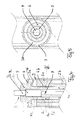
- the height-adjustable storage unit is assigned according to the first example of the invention a structural unit, according to FIG. 1 consists of a carriage 11, a hinged at one end to this extension arm 8 and a support profile 1, wherein the profile 1 in the lower region of a sash (not shown) can be fastened.
- the profile 1 is connected to the other end of the stay 8.
- the axis 7 * (or 13) passes through a rod member 7,9.
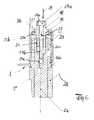
- the storage unit consists of the FIGS. 2 to 5 from a bearing pin 4, which is pressed with its lower portion 4a in a corresponding opening of the stay 8. It protrudes from below into a first recess 1 * of the support profile 1 and is rotatably and axially displaceably mounted in the recess 1 * by means of two radial bearings arranged at an axial distance, in particular in the form of needle sleeves 2a and 2b.
- the needle sleeves are arranged in a bearing bush 3, which is anchored with its lower portion 3b in the recess of the support profile 1 and at the upper end to a flange 3a is formed.
- a support surface for example, arranged as a bearing plate 6, against which a radially outwardly projecting collar 16 of a coaxial with the bearing pin 4 arranged, rotatable bearing part 5 is supported on the flange 3a of the bearing bush 3 rests.
- the bearing part is rotatably mounted in a second recess 1 'of the profile 1 or storable when the suitability of the height-adjustable storage unit is in demand.
- the bearing pin 4 has, in its upper region 4b, a wide coaxial cylindrical recess 15 extending from its end face and carrying an internal thread 15a over the greater part of its length. With this internal thread is an external thread 5d on a cylindrical projection 5c at the lower end of the bearing part 5 in adjusting engagement.
- the bearing pin 4 is fixedly connected to the stay arm 8 and the bearing member 5 is rotatably mounted axially non-displaceably in the second recess 1 'of the support profile 1, a rotation of the bearing part leads to a change in height of the unit from bearing part 5 and support profile 1 and thus also the with the support profile firmly connected wing.
- the recesses 1 'and 1 * are coaxial or in alignment.
- bearing pin 4 and the bearing part 5 do not rotate against each other during operational pivoting movements of the extension arm 8 and there is no unwanted height adjustment.
- the bore 4c of the bearing pin 4 has a polygonal cross-section over most of its length.
- An identical cross-section is provided - at least in the lower region - of the bore 5b.
- the narrower hole continues the wide cylindrical recess 15 down.
- the holes is also a rod-shaped element, which can also consist of two parts 7 and 9, as shown, assigned.
- the lower part 9 of the rod points like FIGS. 4 and 5 can be removed, a corresponding to the cross section of the bore in the bearing bolt polygonal cross section, while the upper part 7 has a cross section, which - as well as the FIGS. 4 and 5 can be taken - circular and so much smaller that it is free and relatively rotatable in the polygonal cross-section movable, at least that of the upper bore 5b.
- the upper part 7 of the rod-shaped element has a lower portion 7a in contact y with the lower part 9 and at the top a contrast again rejuvenated end 7b, which can escape through a correspondingly narrow bore 5a of the bearing part, such as Figures 2 and 4 demonstrate.
- FIG. 2 and 4 show the state in which a height adjustment is locked, since the rod-shaped element with the lower part 9 in the polygonal openings 4c, 5b of both parts, bearing pin 4 and bearing part 5, engages and both rotatably together, that is positively connected.
- a pushing out of the rod member 7,9 is prevented by the abutment of a step x between the sections 7a and 7b, which step comes to rest against the underside of the opening 5a, as well as the FIG. 4 clearly shows.
- the rod 17 engages through an aligned bore 25b in the bearing part 25.
- the alignment results with bore 24a.
- the locking element 17 is released from the bearing pin 24 and tightened again after the adjustment to produce the necessary adhesion.
- FIG. 6 are the ones with the corresponding parts of the design FIGS. 2 to 5 matching parts as follows: support profile 23, arranged in a bearing bush needle bearings 20a and 20b, threaded engagement portion 21 between the bearing pin 24 and bearing member 25, outwardly projecting collar 25a of the bearing member 25, the associated bearing plate 26, the extension arm 28, and an upper extension 18th the bearing part 25, which has an outer contour for an adjusting tool
- the bearing part can reliably absorb even large wing loads on the radial collar of the support profile and transmitted over the longer threaded engagement area between the bearing part and the bearing pin securely on this and thus on the extension.
- the parts are easy to manufacture and introduce after pre-assembly as a unit from below into the corresponding recess of the support profile.
- Both versions - form fit or traction - provide a reliable adjustment lock for operational movements and are both easy to operate.
Landscapes
- Engineering & Computer Science (AREA)
- Mechanical Engineering (AREA)
- Hinges (AREA)
- Closing And Opening Devices For Wings, And Checks For Wings (AREA)
- Pivots And Pivotal Connections (AREA)
Abstract
Description
- Die Erfindung betrifft eine höhenverstellbare Lagereinheit eines Laufwagens für Abstell-Schiebetüren oder -fenster (kurz: Flügel) und dient zum Verbinden eines an dem Laufwagen schwenkbar befestigten Ausstellarmes mit einem an einem unteren Flügelprofil befestigbaren Stützprofil. Das Arbeitsverfahren zu der Lagerung ist ebenso erfasst.
- Derartige Lagereinheiten sind bekannt, zum Beispiel aus der
EP-B 119 434 - Im bekannten Fall ist der Lagerbolzen mittels zweier im axialen Abstand angeordneten Nadellager in einer Lagerbuchse gelagert, die mittels Außengewinde in einem Gehäuseteil höhenverstellbar angeordnet ist. Der Lagerbolzen ist an seinem oberen Ende mittels eines Sprengringes verschiebefest mit der Lagerbuchse verbunden. Um die eingestellte Stellung der Lagerbuchse gegenüber dem Gehäuseteil zu sichern, ist an der Seite des Gehäuseteils eine Stellschraube vorgesehen, die für eine Verstellung gelöst und nach der erfolgten Verstellung fest angezogen wird.
- Bei der Lagereinheit nach der
EP-B 1 054 126 (von GU), bei der zur Verstellung ein in axialer Fluchtung mit dem Lagerbolzen im Gehäuseteil schraubbarer Lagerteil vorgesehen ist, wird eine Sicherung der Einstellung mit Hilfe eines Sicherungsschiebers erreicht, der im Gehäuseteil quer zur Achse von Lagerteil und Lagerbolzen zwischen zwei Stellungen verschiebbar ist. In der einen Stellung bietet er dem Lagerteil eine das Drehen des Lagerteils ermöglichende Öffnung und in der anderen Stellung eine das Drehen verhindernde kleinere Öffnung dar. - Es ist Aufgabe der Erfindung, eine höhenverstellbare Lagereinheit der genannten Art zu verwirklichen, die große Flügellasten sicher aufnehmen und auf den Ausstellarm übertragen kann. Sie soll bei einfachem Aufbau und einfacher Montage gute Lagereigenschaften und Sicherheit (Sicherung) der eingestellten Höhenstellung erreichen.
- Diese Aufgabe wird durch Anspruch 1 oder 10 oder 13 gelöst.
- Die über ein Gewinde verstellbar zusammenwirkenden Bereiche von Lagerteil und Lagerbolzen können bei einfacher Herstellung eine große Eingriffslänge und damit eine sichere Übertragung der Flügellast gewährleisten, die das Lagerteil vom Stützprofil ebenso sicher übernehmen kann. Zugleich kann - wiederum bei einfacher Herstellungsmöglichkeit - eine zuverlässige Lagesicherung der Teile in ihrer eingestellten relativen Lage gewährleistet werden, sei es durch Formschluss oder durch Kraftschluss zwischen den beiden Teilen (Lagerteil und Lagerbolzen), wenn betriebliche Bewegungen keine axiale Höhenverstellung bewirken dürfen.
- Entlang Lagerteil und Lagerbolzen und einer gemeinsamen Achse verlaufende und miteinander fluchtende Bohrungen sind optionell aber vorteilhaft. Sie sind geeignet zur Aufnahme eines federkraft-belasteten und einen Formschluss zwischen Lagerbolzen und Lagerteil bildenden stangenförmigen Elements. Der Formschluss kann durch axiales Hereindrücken gelöst werden. Eine Verstellung der Höhe kann dann erfolgen, bezogen auf die "höhenverstellbare Lagereinheit".
- Alternativ kann ein - einen Kraftschluss zwischen Lagerbolzen und Lagerteil bildendes - stangenförmiges Element vorgesehen sein, wenn betriebliche Bewegungen keine axiale Höhenverstellung bewirken dürfen.
- Die abhängigen Ansprüche sind vorteilhafte Weiterbildungen, keine notwendigen Vervollständigungen der unabhängigen Ansprüche.
- Weitere Vorteile und Einzelheiten der Erfindung ergeben sich aus der nachfolgenden Beschreibung der Erfindung an Hand von Beispielen und den nachfolgend aufgeführten Figuren.
- Figur 1
- zeigt in perspektivischer Ansicht eine Einheit aus Laufwagen 11, Stützprofil 1 und dem verbindenden Ausstellarm 8, welcher Einheit eine "höhenverstellbare Lagereinheit" zugeordnet ist.
- Figur 2 Figur 3
- zeigen jeweils im axialen Schnitt die höhenverstellbare Lagereinheit einmal in einer eingestellten und fixierten Stellung und einmal in der - eine Verstellung zulassenden - Stellung.
- Figur 4
- zeigt im axialen Schnitt und im vergrößerten Maßstab den oberen Bereich der höhenverstellbaren Lagereinheit.
- Figur 5
- zeigt einen horizontalen Schnitt entlang der Schnittebene A-A von
Figur 2 . - Figur 6
- zeigt im axialen Schnitt eine alternative Ausführung der höhenverstellbaren Lagereinheit.
- Die höhenverstellbare Lagereinheit ist gemäß dem ersten Beispiel der Erfindung einer Baueinheit zugeordnet, die gemäß
Figur 1 aus einem Laufwagen 11, einem mit einem Ende an diesem angelenkten Ausstellarm 8 und einem Stützprofil 1 besteht, wobei das Profil 1 im unteren Bereich eines Flügelrahmens (nicht gezeigt) befestigbar ist. Über die höhenverstellbare Lagereinheit 12 ist das Profil 1 mit dem anderen Ende des Ausstellarmes 8 verbunden. - Die Achse 7* (oder 13) verläuft durch ein Stangenelement 7,9.
- Die Lagereinheit besteht nach den
Figuren 2 bis 5 aus einem Lagerbolzen 4, der mit seinem unteren Abschnitt 4a in eine entsprechende Öffnung des Ausstellarmes 8 eingepresst ist. Er ragt von unten in eine erste Ausnehmung 1* des Stützprofils 1 und ist mittels zweier, im axialen Abstand angeordneter Radiallager, insbesondere in Form von Nadelhülsen 2a und 2b, drehbar und axial verschiebbar in der Ausnehmung 1 * gelagert. - Die Nadelhülsen sind in einer Lagerbüchse 3 angeordnet, die mit ihrem unteren Abschnitt 3b in der Ausnehmung des Stützprofils 1 verankert und am oberen Ende zu einem Flansch 3a umgeformt ist.
- Am oberen Ende der ersten Ausnehmung 1* des Stützprofils 1 ist eine Stützfläche, beispielsweise als Lagerscheibe 6 angeordnet, gegenüber der sich ein radial nach außen ragender Bund 16 eines koaxial zum Lagerbolzen 4 angeordneten, drehbaren Lagerteils 5 abstützt, das auf dem Flansch 3a der Lagerbüchse 3 aufliegt. Das Lagerteil ist drehbar in einer zweiten Ausnehmung 1' des Profils 1 gelagert oder lagerfähig, wenn die Eignung der höhenverstellbaren Lagereinheit gefragt ist.
- Der Lagerbolzen 4 weist in seinem oberen Bereich 4b eine von seiner Stirnfläche ausgehende, weite koaxiale zylindrische Ausnehmung 15 auf, die über den größeren Teil ihrer Länge ein Innengewinde 15a trägt. Mit diesem Innengewinde steht ein Außengewinde 5d an einem zylindrischen Ansatz 5c am unteren Ende des Lagerteils 5 in Verstelleingriff.
- Da der Lagerbolzen 4 fest mit dem Ausstellarm 8 verbunden und das Lagerteil 5 axial unverschieblich in der zweiten Ausnehmung 1' des Stützprofils 1 drehbar gelagert ist, führt eine Drehung des Lagerteils zu einer höhenmäßigen Lageveränderung der Einheit aus Lagerteil 5 und Stützprofil 1 und damit auch des mit dem Stützprofil fest verbundenen Flügels. Die Ausnehmungen 1' und 1* sind koaxial oder fluchtend.
- Die Höhenänderung (höhenmäßige Lageveränderung) erfolgt gegenüber dem Lagerbolzen 4.
- Nach dem Höhenverstell-Vorgang verdrehen sich der Lagerbolzen 4 und das Lagerteil 5 bei betrieblichen Schwenkbewegungen des Ausstellarmes 8 nicht gegeneinander und es ergibt sich keine ungewollte Höhenverstellung. Dazu weisen Lagerbolzen und Lagerteil miteinander fluchtende engere Bohrungen (oder Öffnungen) 4c bzw. 5b auf.
- Die Bohrung 4c des Lagerbolzens 4 weist über den größten Teil ihrer Länge einen mehrkantigen Querschnitt auf. Ein gleicher Querschnitt ist - wenigstens im unteren Bereich - der Bohrung 5b vorgesehen. Die engere Bohrung setzt die weite zylindrische Ausnehmung 15 nach unten fort.
- Am Boden der Bohrung 4c des Lagerbolzens ist eine Rückstell-Schraubenfeder 10 angeordnet. Den Bohrungen ist außerdem ein stangenförmiges Element, das wie dargestellt auch aus zwei Teilen 7 und 9 bestehen kann, zugeordnet.
- Der untere Teil 9 der Stange weist, wie
Figur 4 und 5 entnommen werden kann, einen dem Querschnitt der Bohrung im Lagerbolzen entsprechenden mehrkantigen Querschnitt auf, während der obere Teil 7 einen Querschnitt aufweist, der - wie ebenfalls denFiguren 4 und 5 entnommen werden kann - kreisförmig und soviel kleiner ist, dass er frei und relativdrehbar in dem mehrkantigen Querschnitt bewegbar ist, zumindest dem der oberen Bohrung 5b. Der obere Teil 7 des stangenförmigen Elementes weist einen unteren Abschnitt 7a in Kontakt y mit dem unteren Teil 9 auf und oben einen demgegenüber nochmals verjüngtes Ende 7b, das durch eine entsprechend enge Bohrung 5a des Lagerteils austreten kann, wieFiguren 2 und4 zeigen. - Die Stellung der Teile in
Figur 2 und4 zeigen den Zustand, in dem eine Höhenverstellung gesperrt ist, da das stangenförmige Element mit dem unteren Teil 9 in die mehrkantig ausgebildeten Öffnungen 4c, 5b beider Teile, Lagerbolzen 4 und Lagerteil 5, eingreift und beide miteinander drehfest, das heißt formschlüssig verbindet. - Wenn dagegen, wie in
Figur 3 durch den oberen Pfeil 14 angedeutet, ein entsprechendes (nicht dargestelltes) Werkzeug durch die Öffnung 5a eingeführt wird, wird das stangenförmige Element 7,9 gegen die Wirkung der Rückstellfeder 10 nach unten gedrückt, bis der mehrkantige untere Teil 9 außer Eingriff mit der mehrkantigen Öffnung 5b des Lagerteils 5 kommt, sodass das Lagerteil 5 mittels des eingeführten Werkzeuges und einer entsprechenden Konturierung der engeren Bohrung 5a gegenüber dem Lagerbolzen 4 zur Höhenveränderung gedreht werden kann. Wird das Werkzeug aus der konturierten Öffnung 5a zurückgezogen (heraus genommen), drückt die Feder 10 das Stangenelement 7,9 wieder in die Sperrstellung nachFigur 2 . - Ein Herausdrücken des Stangenelements 7,9 wird durch die eine Anlage einer Stufe x zwischen den Abschnitten 7a und 7b verhindert, welche Stufe zur Anlage an die Unterseite der Öffnung 5a gelangt, wie auch die
Figur 4 deutlich zeigt. - Bei der Ausführung nach
Figur 6 ist die generelle Anordnung und Ausbildung der Teile die Gleiche wie in denFiguren 2 bis 5 . - Im Unterschied wird hier jedoch die Sperrung der Teile gegen ungewollte Verstellung nicht durch Formschluss, sondern durch Kraftschluss verwirklicht. Dazu ist Bohrung 24a im Lagerbolzen 24 als Gewindebohrung ausgebildet und das durchgehende stangenförmige Sperrelement 17 ist über einen entsprechend langen unteren Abschnitt 17b mit einem entsprechenden Außengewinde versehen. Am oberen Ende des Sperrelementes ist ein Kopf 17a ausgebildet, der in einer Ausnehmung 18a des Lagerteils 25 drehbar aufgenommen ist und eine konturierte Ausnehmung für das Einsetzen (siehe Pfeil 19) eines Werkzeuges aufweist.
- Die Stange 17 greift durch eine fluchtende Bohrung 25b im Lagerteil 25. Die Fluchtung ergibt sich mit Bohrung 24a.
- Zur Höhenverstellung wird das Sperrelement 17 vom Lagerbolzen 24 gelöst und nach der Verstellung wieder fest angezogen, um den notwendigen Kraftschluss herzustellen.
- In
Figur 6 sind die mit den entsprechenden Teilen der Ausführung nachFiguren 2 bis 5 übereinstimmenden Teile wie folgt bezeichnet: Stützprofil 23, in einer Lagerbüchse angeordnete Nadellager 20a und 20b, Gewindeeingriffsbereich 21 zwischen Lagerbolzen 24 und Lagerteil 25, nach außen ragender Bund 25a des Lagerteils 25, die zugehörige Lagerscheibe 26, der Ausstellarm 28, und ein oberer Fortsatz 18 des Lagerteils 25, der eine Außenkonturierung für ein Verstellwerkzeug aufweist - Bei beiden Ausführungen kann das Lagerteil zuverlässig auch große Flügellasten über den radialen Kragen vom Stützprofil aufnehmen und über den längeren GewindeEingriffsbereich zwischen dem Lagerteil und dem Lagerbolzen sicher auf diesen und damit auf den Ausstellarm übertragen. Die Teile sind einfach herzustellen und nach Vormontierung als Einheit von unten in die entsprechende Ausnehmung des Stützprofils einzuführen.
- Beide Ausführungen - Formschluss oder Kraftschluss - ergeben eine zuverlässige Verstellsperre für betriebliche Bewegungen und lassen sich beide leicht bedienen.
Claims (13)
- Höhenverstellbare Lagereinheit (12) für einen Laufwagen (11) einer Abstellschiebetür oder eines -fensters als Flügel zum Verbinden eines an dem Laufwagen schwenkbar befestigten Ausstellarmes (8) mit einem an einem unteren Flügelrand befestigbaren Stützprofil (1), wobei die Lagereinheit einen Lagerbolzen (4) aufweist, der mit seinem unteren Ende (4a) formschlüssig in dem Ausstellarm (8) eingepresst ist und axial verstellbar und drehbar in einer ersten Ausnehmung (1*) des Stützprofils (1) lagerfähig ist;- wobei der Lagerbolzen (4,24) zusammen mit einem Lagerteil (5,25) eine zweiteilige Verstelleinheit bildet;- wobei der Lagerbolzen oben eine mit einem Innengewinde (15a) versehene zylindrische Ausnehmung (15) und der Lagerteil einen mit entsprechendem Außengewinde (5d) versehenen zylindrischen Ansatz (5c) aufweist;- wobei der Lagerteil (5,25) ausgebildet ist, in einer zweiten Ausnehmung (1') des Stützprofils (1) axial unbeweglich, aber drehbar so gelagert zu werden, dass die vom Stützprofil übertragene Last sicher aufnehmbar ist und über die Gewindeverbindung (15a,5d;21) auf den Lagerbolzen übertragbar ist, und bei der das Lagerteil (5,25) und der Lagerbolzen (4,24) entlang einer gemeinsamen Achse (7*,13) verlaufende und miteinander fluchtende Bohrungen (5b,4c;24a,25b) zur Aufnahme eines stangenförmigen Elements (7,9;17) aufweisen, um in einer die Höhenverstellung nicht zulassenden Position/Stellung das federbelastete und einen Formschluss zwischen Lagerbolzen und Lagerteil (4,5) bildende Stangenelement (7,9) oder das einen Kraftschluss zwischen Lagerbolzen und Lagerteil (24,25) bildende Stangenelement (17) aufzunehmen.
- Höhenverstellbare Lagereinheit (12) nach Anspruch 1, bei der das Lagerteil (5) im axialen Abstand unter seinem oberen, für das Angreifen eines Verstellwerkzeuges profilierten Ende (5a) einen radial nach außen ragenden Bund (16) aufweist, der - vorzugsweise unter Zwischenschaltung einer Lagerscheibe (6,26) - am Ende der ersten Ausnehmung (1*) des Stützprofils (1) gelagert ist.
- Höhenverstellbare Lagereinheit (12) nach Anspruch 2, bei der die Lagerscheibe (6) aus einem verschleißfesten Kunststoff mit (guten) Gleiteigenschaften besteht.
- Höhenverstellbare Lagereinheit (12) nach einem der Ansprüche 2 oder 3, bei der das Lagerteil (5) axial von unten durch das obere Ende (3a) einer in der ersten Ausnehmung (1*) fest verankerten und zwei im axialen Abstand angeordnete Radiallager (2a,2b), insbesondere in Form von Nadelhülsen, aufweisende Lagerbüchse (3) lagegesichert ist.
- Höhenverstellbare Lagereinheit (12) nach einem der voranstehenden Ansprüche, bei der zur Bildung des Formschlusses die Bohrung (4c) im Lagerbolzen ebenso wie die Bohrung (5b) im Lagerteil im Querschnitt mehreckig ausgebildet sind und die Bohrung im Lagerbolzen in ihrem Grundbereich, insbesondere an ihrem Boden eine Rückstellfeder (10) aufweist, und das - vorzugsweise zweiteilig ausgebildete - stangenförmige Element (7,9) in seinem unteren Bereich oder unteren Teil (9) einen dem mehreckigen Querschnitt der Bohrungen (4c,5b) angepassten Querschnitt aufweist, und das stangenförmige Element in seinem oberen Bereich oder Teil (7) einen verminderten Querschnitt aufweist, der in zumindest der oberen der mehreckigen Bohrungen frei drehbar ist und mit einem weiter verjüngten Ende (7b) durch eine entsprechend bemessene Öffnung (5a) an der oberen Stirnseite des Lagerteils - in der Formschlussstellung des stangenförmigen Elementes - ragt.
- Höhenverstellbare Lagereinheit (12) nach Anspruch 5, bei der die Öffnung (5a) an der oberen Stirnseite des Lagerteils als Mehrkantöffnung für einen Verstellschlüssel ausgebildet ist.
- Höhenverstellbare Lagereinheit (12) nach einem der Ansprüche 1 bis 4, bei der zur Bildung des Kraftschlusses die Bohrung (24a) im Lagerbolzen (24) als Gewindebohrung ausgebildet ist und das stangenförmige Element (17) an seinem unteren Bereich (17b) einen entsprechenden Gewindeabschnitt aufweist, der bei hergestelltem Kraftschluss mit der Gewindebohrung im Lagerbolzen in Eingriff steht und zugleich mit einem Kopfteil (17a), der mit einem Mehrkant für den Eingriff eines Verstellwerkzeuges ausgebildet ist, auf der Oberseite oder in einer dort ausgebildeten Vertiefung (18a) liegt, um durch Anziehen oder Drehen des stangenförmigen Elementes zwischen Lagerteil und Lagerbolzen einen Kraftschluss zu erzielen.
- Lagereinheit nach Anspruch 5, wobei die Bohrung im Lagerteil (5) wenigstens im unteren Bereich mehreckig ausgebildet ist.
- Lagereinheit nach Anspruch 8 oder Anspruch 5, wobei die Bohrung (4c,15) im Lagerbolzen (4) zumindest über den größten Teil ihrer Länge mehrkantig ausgebildet ist, insbesondere der obere Abschnitt einer engeren Bohrung (4c).
- Höhenverstellbare Lagereinheit zum Verbinden eines an einem Laufwagen schwenkbar befestigten Ausstellarmes (8) mit einem an einem unteren Flügelrand eines Flügels befestigbaren Stützprofil (1),(a) die Lagereinheit mit einem Lagerbolzen (4), der mit seinem unteren Ende (4a) formschlüssig in dem Ausstellarm (8) eingepresst ist und axial verstellbar sowie drehbar in einer ersten Ausnehmung (1*) des Stützprofils (1) lagerfähig ist;(b) wobei der Lagerbolzen zusammen mit einem Lagerteil (5) eine zweiteilige Verstelleinheit bildet, für die der Lagerbolzen oben eine mit Innengewinde (15a) versehene zylindrische Ausnehmung (15) und der Lagerteil einen mit entsprechendem Außengewinde (5d) versehenen zylindrischen Ansatz (5c) aufweist;(c) wobei der Lagerteil (5) ausgebildet ist, in einer zweiten Ausnehmung (1') des Stützprofils (1) axial fest, aber drehbar so gelagert zu werden, dass eine vom Stützprofil übertragene Last aufnehmbar ist und über die Gewindeverbindung (15a,5d;21) auf den Lagerbolzen übertragbar ist.
- Lagereinheit nach Anspruch 8, wobei das Lagerteil (5) und der Lagerbolzen (4) entlang einer gemeinsamen Achse (7*) verlaufende und miteinander fluchtende Bohrungen (5b;4c) aufweisen, geeignet zur Aufnahme eines federkraft-belasteten und in einer Stellung einen Formschluss zwischen Lagerbolzen und Lagerteil bildenden stangenförmigen Elements (7,9).
- Lagereinheit nach Anspruch 10, wobei fluchtende Bohrungen (24a,25b) in Lagerteil und Lagerbolzen eine Stange (17) aufnehmen, die in der einen Stellung/Drehlage einen Kraftschluss zwischen Lagerbolzen und Lagerteil bildet.
- Verfahren zur Lagerung eines an einem Laufwagen schwenkbar befestigten Ausstellarmes (8) mit einem an einem unteren Flügelrand eines Flügels befestigbaren Stützprofil (1), wobei eine der Lagereinheiten von Anspruch 1 oder 10 verwendbar ist oder verwendet wird.
Applications Claiming Priority (2)
| Application Number | Priority Date | Filing Date | Title |
|---|---|---|---|
| DE102006059571 | 2006-12-16 | ||
| DE102007022311.2A DE102007022311B4 (de) | 2006-12-16 | 2007-05-12 | Höhenverstellbare Lagereinheit für einen Schiebeflügel |
Publications (3)
| Publication Number | Publication Date |
|---|---|
| EP1936084A2 true EP1936084A2 (de) | 2008-06-25 |
| EP1936084A3 EP1936084A3 (de) | 2013-07-10 |
| EP1936084B1 EP1936084B1 (de) | 2015-07-15 |
Family
ID=39027440
Family Applications (1)
| Application Number | Title | Priority Date | Filing Date |
|---|---|---|---|
| EP07123285.4A Not-in-force EP1936084B1 (de) | 2006-12-16 | 2007-12-14 | Höhenverstellbare Lagereinheit für einen Schiebeflügel |
Country Status (2)
| Country | Link |
|---|---|
| EP (1) | EP1936084B1 (de) |
| DE (1) | DE102007022311B4 (de) |
Cited By (4)
| Publication number | Priority date | Publication date | Assignee | Title |
|---|---|---|---|---|
| DE102014219578A1 (de) | 2014-09-26 | 2016-03-31 | Roto Frank Ag | Lagereinheit mit einer Hülse |
| EP2384386B1 (de) | 2009-01-11 | 2017-03-01 | HAUTAU GmbH | Kompakter laufwagen fuer einen laengs-beweglichen, schweren fluegel |
| EP2538009B1 (de) | 2009-01-11 | 2017-06-28 | HAUTAU GmbH | Kompakter Laufwagen für einen Fluegel mit einer parallel-abgestellten, gesicherten Lage |
| EP3222804A1 (de) * | 2016-03-24 | 2017-09-27 | HAUTAU GmbH | Laufwagen für einen parallel abstellbaren flügel |
Citations (3)
| Publication number | Priority date | Publication date | Assignee | Title |
|---|---|---|---|---|
| DE3040375A1 (de) | 1980-10-25 | 1982-05-27 | Keller, Eberhard, 7121 Freudental | Beschlag fuer metall-fenster oder -tueren |
| EP0119434B1 (de) | 1983-03-19 | 1988-04-06 | Gretsch-Unitas GmbH Baubeschläge | Zumindest an seinem unteren Ende ausstellbarer Flügel eines Fensters, einer Tür od. dgl. |
| EP1054126B1 (de) | 1999-05-21 | 2004-09-01 | Gretsch-Unitas GmbH Baubeschläge | Laufschuh eines Parallelschiebe- und Kippbeschlages |
Family Cites Families (2)
| Publication number | Priority date | Publication date | Assignee | Title |
|---|---|---|---|---|
| DE1708860A1 (de) * | 1964-06-20 | 1971-05-13 | Paul Zahn | Anschweissband fuer Tueren,Fenster od. dgl. |
| DE102006057191A1 (de) * | 2006-12-05 | 2008-07-31 | Schaeffler Kg | Ausstellbarer Flügel |
-
2007
- 2007-05-12 DE DE102007022311.2A patent/DE102007022311B4/de not_active Expired - Fee Related
- 2007-12-14 EP EP07123285.4A patent/EP1936084B1/de not_active Not-in-force
Patent Citations (3)
| Publication number | Priority date | Publication date | Assignee | Title |
|---|---|---|---|---|
| DE3040375A1 (de) | 1980-10-25 | 1982-05-27 | Keller, Eberhard, 7121 Freudental | Beschlag fuer metall-fenster oder -tueren |
| EP0119434B1 (de) | 1983-03-19 | 1988-04-06 | Gretsch-Unitas GmbH Baubeschläge | Zumindest an seinem unteren Ende ausstellbarer Flügel eines Fensters, einer Tür od. dgl. |
| EP1054126B1 (de) | 1999-05-21 | 2004-09-01 | Gretsch-Unitas GmbH Baubeschläge | Laufschuh eines Parallelschiebe- und Kippbeschlages |
Cited By (5)
| Publication number | Priority date | Publication date | Assignee | Title |
|---|---|---|---|---|
| EP2384386B1 (de) | 2009-01-11 | 2017-03-01 | HAUTAU GmbH | Kompakter laufwagen fuer einen laengs-beweglichen, schweren fluegel |
| EP2538009B1 (de) | 2009-01-11 | 2017-06-28 | HAUTAU GmbH | Kompakter Laufwagen für einen Fluegel mit einer parallel-abgestellten, gesicherten Lage |
| DE102014219578A1 (de) | 2014-09-26 | 2016-03-31 | Roto Frank Ag | Lagereinheit mit einer Hülse |
| DE102014219578B4 (de) | 2014-09-26 | 2020-07-02 | Roto Frank Ag | Lagereinheit mit einer Hülse |
| EP3222804A1 (de) * | 2016-03-24 | 2017-09-27 | HAUTAU GmbH | Laufwagen für einen parallel abstellbaren flügel |
Also Published As
| Publication number | Publication date |
|---|---|
| EP1936084B1 (de) | 2015-07-15 |
| DE102007022311B4 (de) | 2016-03-10 |
| EP1936084A3 (de) | 2013-07-10 |
| DE102007022311A1 (de) | 2008-06-19 |
Similar Documents
| Publication | Publication Date | Title |
|---|---|---|
| EP0886071B1 (de) | Schraubeinheit | |
| EP2586944B1 (de) | Scharnier mit Verstellelementen und Verstellkrone für diese Verstellelemente | |
| EP3170694B1 (de) | Armlehne | |
| EP0807738A2 (de) | Mit einem aushängbaren Türscharnier baulich vereinigter Türfeststeller | |
| EP2997868B1 (de) | Befestigungsvorrichtung für einen Toilettendeckel und einen Toilettensitz an einer Toilettenkeramik | |
| EP1936084B1 (de) | Höhenverstellbare Lagereinheit für einen Schiebeflügel | |
| EP2169163B1 (de) | Höhenverstellbares Band | |
| EP3807012B1 (de) | Zentrifuge | |
| DE29713995U1 (de) | Türscharnier mit Feststeller | |
| DE3418138C2 (de) | Bandzapfenbüchse | |
| EP3150786A1 (de) | Gelenkverbindung | |
| DE8804008U1 (de) | Scharnier | |
| EP0893564B1 (de) | Drehlager für Fenster oder Türen | |
| DE3137112A1 (de) | Aushaengbares tuerscharnier | |
| EP3887631B1 (de) | Bandlappen und band zur um eine scharnierachse scharniergelenkigen verbindung eines flügels mit einem rahmen | |
| WO2000047852A1 (de) | Scharnier mit arretierung | |
| EP2740872B1 (de) | Zur verdeckten anordnung vorgesehenes ecklager | |
| EP2418344B1 (de) | Türflügelbandteil, Türbandvorrichtung sowie Verwendungen derselben | |
| DE102006001509B3 (de) | Scharnier für Türen oder Fenster sowie Verfahren zum Einsetzen eines für die Verstellung notwendigen Scharnierzapfens in einen Scharnierkopf bei einem Scharnier | |
| DE20210361U1 (de) | Laufwagen für Schiebe- oder Kipp-Schiebe-Fenster oder -Türen | |
| EP1983133B1 (de) | Scharnierbeschlag eines Fensters, einer Tür oder dgl. sowie Verfahren zur Montage des Scharnierbeschlags | |
| WO2009006876A2 (de) | Kraftfahrzeugscharnier | |
| DE102006022184A1 (de) | Führungs- und Drehlager für eine Klapp-/Schiebeverglasung | |
| EP3278693B1 (de) | Beschlag für eine schiebetüre | |
| EP1793067B1 (de) | Beschlag für Türen, Fenster oder dgl. |
Legal Events
| Date | Code | Title | Description |
|---|---|---|---|
| PUAI | Public reference made under article 153(3) epc to a published international application that has entered the european phase |
Free format text: ORIGINAL CODE: 0009012 |
|
| AK | Designated contracting states |
Kind code of ref document: A2 Designated state(s): AT BE BG CH CY CZ DE DK EE ES FI FR GB GR HU IE IS IT LI LT LU LV MC MT NL PL PT RO SE SI SK TR |
|
| AX | Request for extension of the european patent |
Extension state: AL BA HR MK RS |
|
| PUAL | Search report despatched |
Free format text: ORIGINAL CODE: 0009013 |
|
| AK | Designated contracting states |
Kind code of ref document: A3 Designated state(s): AT BE BG CH CY CZ DE DK EE ES FI FR GB GR HU IE IS IT LI LT LU LV MC MT NL PL PT RO SE SI SK TR |
|
| AX | Request for extension of the european patent |
Extension state: AL BA HR MK RS |
|
| RIC1 | Information provided on ipc code assigned before grant |
Ipc: E05D 15/10 20060101AFI20130531BHEP |
|
| 17P | Request for examination filed |
Effective date: 20140110 |
|
| RBV | Designated contracting states (corrected) |
Designated state(s): AT BE BG CH CY CZ DE DK EE ES FI FR GB GR HU IE IS IT LI LT LU LV MC MT NL PL PT RO SE SI SK TR |
|
| AKX | Designation fees paid |
Designated state(s): AT BE BG CH CY CZ DE DK EE ES FI FR GB GR HU IE IS IT LI LT LU LV MC MT NL PL PT RO SE SI SK TR |
|
| 17Q | First examination report despatched |
Effective date: 20140401 |
|
| GRAP | Despatch of communication of intention to grant a patent |
Free format text: ORIGINAL CODE: EPIDOSNIGR1 |
|
| INTG | Intention to grant announced |
Effective date: 20141215 |
|
| GRAS | Grant fee paid |
Free format text: ORIGINAL CODE: EPIDOSNIGR3 |
|
| GRAA | (expected) grant |
Free format text: ORIGINAL CODE: 0009210 |
|
| AK | Designated contracting states |
Kind code of ref document: B1 Designated state(s): AT BE BG CH CY CZ DE DK EE ES FI FR GB GR HU IE IS IT LI LT LU LV MC MT NL PL PT RO SE SI SK TR |
|
| REG | Reference to a national code |
Ref country code: CH Ref legal event code: EP Ref country code: GB Ref legal event code: FG4D Free format text: NOT ENGLISH |
|
| REG | Reference to a national code |
Ref country code: IE Ref legal event code: FG4D Free format text: LANGUAGE OF EP DOCUMENT: GERMAN |
|
| REG | Reference to a national code |
Ref country code: AT Ref legal event code: REF Ref document number: 736896 Country of ref document: AT Kind code of ref document: T Effective date: 20150815 |
|
| REG | Reference to a national code |
Ref country code: DE Ref legal event code: R096 Ref document number: 502007014058 Country of ref document: DE |
|
| REG | Reference to a national code |
Ref country code: CH Ref legal event code: NV Representative=s name: ISLER AND PEDRAZZINI AG, CH |
|
| REG | Reference to a national code |
Ref country code: NL Ref legal event code: FP |
|
| REG | Reference to a national code |
Ref country code: LT Ref legal event code: MG4D |
|
| PG25 | Lapsed in a contracting state [announced via postgrant information from national office to epo] |
Ref country code: FI Free format text: LAPSE BECAUSE OF FAILURE TO SUBMIT A TRANSLATION OF THE DESCRIPTION OR TO PAY THE FEE WITHIN THE PRESCRIBED TIME-LIMIT Effective date: 20150715 Ref country code: GR Free format text: LAPSE BECAUSE OF FAILURE TO SUBMIT A TRANSLATION OF THE DESCRIPTION OR TO PAY THE FEE WITHIN THE PRESCRIBED TIME-LIMIT Effective date: 20151016 Ref country code: LV Free format text: LAPSE BECAUSE OF FAILURE TO SUBMIT A TRANSLATION OF THE DESCRIPTION OR TO PAY THE FEE WITHIN THE PRESCRIBED TIME-LIMIT Effective date: 20150715 Ref country code: LT Free format text: LAPSE BECAUSE OF FAILURE TO SUBMIT A TRANSLATION OF THE DESCRIPTION OR TO PAY THE FEE WITHIN THE PRESCRIBED TIME-LIMIT Effective date: 20150715 |
|
| PG25 | Lapsed in a contracting state [announced via postgrant information from national office to epo] |
Ref country code: PL Free format text: LAPSE BECAUSE OF FAILURE TO SUBMIT A TRANSLATION OF THE DESCRIPTION OR TO PAY THE FEE WITHIN THE PRESCRIBED TIME-LIMIT Effective date: 20150715 Ref country code: PT Free format text: LAPSE BECAUSE OF FAILURE TO SUBMIT A TRANSLATION OF THE DESCRIPTION OR TO PAY THE FEE WITHIN THE PRESCRIBED TIME-LIMIT Effective date: 20151116 Ref country code: ES Free format text: LAPSE BECAUSE OF FAILURE TO SUBMIT A TRANSLATION OF THE DESCRIPTION OR TO PAY THE FEE WITHIN THE PRESCRIBED TIME-LIMIT Effective date: 20150715 Ref country code: SE Free format text: LAPSE BECAUSE OF FAILURE TO SUBMIT A TRANSLATION OF THE DESCRIPTION OR TO PAY THE FEE WITHIN THE PRESCRIBED TIME-LIMIT Effective date: 20150715 |
|
| REG | Reference to a national code |
Ref country code: DE Ref legal event code: R097 Ref document number: 502007014058 Country of ref document: DE |
|
| PG25 | Lapsed in a contracting state [announced via postgrant information from national office to epo] |
Ref country code: EE Free format text: LAPSE BECAUSE OF FAILURE TO SUBMIT A TRANSLATION OF THE DESCRIPTION OR TO PAY THE FEE WITHIN THE PRESCRIBED TIME-LIMIT Effective date: 20150715 Ref country code: CZ Free format text: LAPSE BECAUSE OF FAILURE TO SUBMIT A TRANSLATION OF THE DESCRIPTION OR TO PAY THE FEE WITHIN THE PRESCRIBED TIME-LIMIT Effective date: 20150715 Ref country code: DK Free format text: LAPSE BECAUSE OF FAILURE TO SUBMIT A TRANSLATION OF THE DESCRIPTION OR TO PAY THE FEE WITHIN THE PRESCRIBED TIME-LIMIT Effective date: 20150715 Ref country code: SK Free format text: LAPSE BECAUSE OF FAILURE TO SUBMIT A TRANSLATION OF THE DESCRIPTION OR TO PAY THE FEE WITHIN THE PRESCRIBED TIME-LIMIT Effective date: 20150715 |
|
| PLBE | No opposition filed within time limit |
Free format text: ORIGINAL CODE: 0009261 |
|
| STAA | Information on the status of an ep patent application or granted ep patent |
Free format text: STATUS: NO OPPOSITION FILED WITHIN TIME LIMIT |
|
| PG25 | Lapsed in a contracting state [announced via postgrant information from national office to epo] |
Ref country code: RO Free format text: LAPSE BECAUSE OF FAILURE TO SUBMIT A TRANSLATION OF THE DESCRIPTION OR TO PAY THE FEE WITHIN THE PRESCRIBED TIME-LIMIT Effective date: 20150715 |
|
| 26N | No opposition filed |
Effective date: 20160418 |
|
| PG25 | Lapsed in a contracting state [announced via postgrant information from national office to epo] |
Ref country code: IS Free format text: LAPSE BECAUSE OF FAILURE TO SUBMIT A TRANSLATION OF THE DESCRIPTION OR TO PAY THE FEE WITHIN THE PRESCRIBED TIME-LIMIT Effective date: 20150715 |
|
| PG25 | Lapsed in a contracting state [announced via postgrant information from national office to epo] |
Ref country code: LU Free format text: LAPSE BECAUSE OF FAILURE TO SUBMIT A TRANSLATION OF THE DESCRIPTION OR TO PAY THE FEE WITHIN THE PRESCRIBED TIME-LIMIT Effective date: 20151214 Ref country code: MC Free format text: LAPSE BECAUSE OF FAILURE TO SUBMIT A TRANSLATION OF THE DESCRIPTION OR TO PAY THE FEE WITHIN THE PRESCRIBED TIME-LIMIT Effective date: 20150715 |
|
| GBPC | Gb: european patent ceased through non-payment of renewal fee |
Effective date: 20151214 |
|
| PG25 | Lapsed in a contracting state [announced via postgrant information from national office to epo] |
Ref country code: SI Free format text: LAPSE BECAUSE OF FAILURE TO SUBMIT A TRANSLATION OF THE DESCRIPTION OR TO PAY THE FEE WITHIN THE PRESCRIBED TIME-LIMIT Effective date: 20150715 |
|
| REG | Reference to a national code |
Ref country code: IE Ref legal event code: MM4A |
|
| REG | Reference to a national code |
Ref country code: FR Ref legal event code: ST Effective date: 20160831 |
|
| PG25 | Lapsed in a contracting state [announced via postgrant information from national office to epo] |
Ref country code: GB Free format text: LAPSE BECAUSE OF NON-PAYMENT OF DUE FEES Effective date: 20151214 Ref country code: IE Free format text: LAPSE BECAUSE OF NON-PAYMENT OF DUE FEES Effective date: 20151214 |
|
| PG25 | Lapsed in a contracting state [announced via postgrant information from national office to epo] |
Ref country code: FR Free format text: LAPSE BECAUSE OF NON-PAYMENT OF DUE FEES Effective date: 20151231 |
|
| PG25 | Lapsed in a contracting state [announced via postgrant information from national office to epo] |
Ref country code: HU Free format text: LAPSE BECAUSE OF FAILURE TO SUBMIT A TRANSLATION OF THE DESCRIPTION OR TO PAY THE FEE WITHIN THE PRESCRIBED TIME-LIMIT; INVALID AB INITIO Effective date: 20071214 Ref country code: BG Free format text: LAPSE BECAUSE OF FAILURE TO SUBMIT A TRANSLATION OF THE DESCRIPTION OR TO PAY THE FEE WITHIN THE PRESCRIBED TIME-LIMIT Effective date: 20150715 |
|
| PG25 | Lapsed in a contracting state [announced via postgrant information from national office to epo] |
Ref country code: CY Free format text: LAPSE BECAUSE OF FAILURE TO SUBMIT A TRANSLATION OF THE DESCRIPTION OR TO PAY THE FEE WITHIN THE PRESCRIBED TIME-LIMIT Effective date: 20150715 |
|
| PG25 | Lapsed in a contracting state [announced via postgrant information from national office to epo] |
Ref country code: MT Free format text: LAPSE BECAUSE OF FAILURE TO SUBMIT A TRANSLATION OF THE DESCRIPTION OR TO PAY THE FEE WITHIN THE PRESCRIBED TIME-LIMIT Effective date: 20150715 |
|
| PGFP | Annual fee paid to national office [announced via postgrant information from national office to epo] |
Ref country code: TR Payment date: 20171213 Year of fee payment: 11 Ref country code: NL Payment date: 20171219 Year of fee payment: 11 |
|
| PGFP | Annual fee paid to national office [announced via postgrant information from national office to epo] |
Ref country code: CH Payment date: 20171221 Year of fee payment: 11 Ref country code: BE Payment date: 20171219 Year of fee payment: 11 Ref country code: AT Payment date: 20171215 Year of fee payment: 11 |
|
| PGFP | Annual fee paid to national office [announced via postgrant information from national office to epo] |
Ref country code: DE Payment date: 20181214 Year of fee payment: 12 |
|
| PGFP | Annual fee paid to national office [announced via postgrant information from national office to epo] |
Ref country code: IT Payment date: 20181218 Year of fee payment: 12 |
|
| REG | Reference to a national code |
Ref country code: CH Ref legal event code: PL |
|
| REG | Reference to a national code |
Ref country code: NL Ref legal event code: MM Effective date: 20190101 |
|
| REG | Reference to a national code |
Ref country code: AT Ref legal event code: MM01 Ref document number: 736896 Country of ref document: AT Kind code of ref document: T Effective date: 20181214 |
|
| PG25 | Lapsed in a contracting state [announced via postgrant information from national office to epo] |
Ref country code: NL Free format text: LAPSE BECAUSE OF NON-PAYMENT OF DUE FEES Effective date: 20190101 |
|
| REG | Reference to a national code |
Ref country code: BE Ref legal event code: MM Effective date: 20181231 |
|
| PG25 | Lapsed in a contracting state [announced via postgrant information from national office to epo] |
Ref country code: BE Free format text: LAPSE BECAUSE OF NON-PAYMENT OF DUE FEES Effective date: 20181231 |
|
| PG25 | Lapsed in a contracting state [announced via postgrant information from national office to epo] |
Ref country code: LI Free format text: LAPSE BECAUSE OF NON-PAYMENT OF DUE FEES Effective date: 20181231 Ref country code: AT Free format text: LAPSE BECAUSE OF NON-PAYMENT OF DUE FEES Effective date: 20181214 Ref country code: CH Free format text: LAPSE BECAUSE OF NON-PAYMENT OF DUE FEES Effective date: 20181231 |
|
| REG | Reference to a national code |
Ref country code: DE Ref legal event code: R119 Ref document number: 502007014058 Country of ref document: DE |
|
| PG25 | Lapsed in a contracting state [announced via postgrant information from national office to epo] |
Ref country code: DE Free format text: LAPSE BECAUSE OF NON-PAYMENT OF DUE FEES Effective date: 20200701 Ref country code: IT Free format text: LAPSE BECAUSE OF NON-PAYMENT OF DUE FEES Effective date: 20191214 |
|
| PG25 | Lapsed in a contracting state [announced via postgrant information from national office to epo] |
Ref country code: TR Free format text: LAPSE BECAUSE OF NON-PAYMENT OF DUE FEES Effective date: 20191214 |