EP1935085B1 - Driver circuit arrangement - Google Patents
Driver circuit arrangement Download PDFInfo
- Publication number
- EP1935085B1 EP1935085B1 EP06809462A EP06809462A EP1935085B1 EP 1935085 B1 EP1935085 B1 EP 1935085B1 EP 06809462 A EP06809462 A EP 06809462A EP 06809462 A EP06809462 A EP 06809462A EP 1935085 B1 EP1935085 B1 EP 1935085B1
- Authority
- EP
- European Patent Office
- Prior art keywords
- energy
- electrical
- subsystem
- circuit arrangement
- driver circuit
- Prior art date
- Legal status (The legal status is an assumption and is not a legal conclusion. Google has not performed a legal analysis and makes no representation as to the accuracy of the status listed.)
- Active
Links
- 238000004146 energy storage Methods 0.000 claims abstract description 28
- 239000003990 capacitor Substances 0.000 claims description 9
- 239000003086 colorant Substances 0.000 description 3
- 230000033228 biological regulation Effects 0.000 description 1
- 238000005286 illumination Methods 0.000 description 1
- 238000009877 rendering Methods 0.000 description 1
Images
Classifications
-
- H—ELECTRICITY
- H05—ELECTRIC TECHNIQUES NOT OTHERWISE PROVIDED FOR
- H05B—ELECTRIC HEATING; ELECTRIC LIGHT SOURCES NOT OTHERWISE PROVIDED FOR; CIRCUIT ARRANGEMENTS FOR ELECTRIC LIGHT SOURCES, IN GENERAL
- H05B45/00—Circuit arrangements for operating light-emitting diodes [LED]
- H05B45/40—Details of LED load circuits
- H05B45/44—Details of LED load circuits with an active control inside an LED matrix
- H05B45/46—Details of LED load circuits with an active control inside an LED matrix having LEDs disposed in parallel lines
-
- H—ELECTRICITY
- H05—ELECTRIC TECHNIQUES NOT OTHERWISE PROVIDED FOR
- H05B—ELECTRIC HEATING; ELECTRIC LIGHT SOURCES NOT OTHERWISE PROVIDED FOR; CIRCUIT ARRANGEMENTS FOR ELECTRIC LIGHT SOURCES, IN GENERAL
- H05B45/00—Circuit arrangements for operating light-emitting diodes [LED]
- H05B45/30—Driver circuits
- H05B45/37—Converter circuits
- H05B45/3725—Switched mode power supply [SMPS]
- H05B45/375—Switched mode power supply [SMPS] using buck topology
-
- H—ELECTRICITY
- H05—ELECTRIC TECHNIQUES NOT OTHERWISE PROVIDED FOR
- H05B—ELECTRIC HEATING; ELECTRIC LIGHT SOURCES NOT OTHERWISE PROVIDED FOR; CIRCUIT ARRANGEMENTS FOR ELECTRIC LIGHT SOURCES, IN GENERAL
- H05B45/00—Circuit arrangements for operating light-emitting diodes [LED]
- H05B45/30—Driver circuits
- H05B45/37—Converter circuits
- H05B45/3725—Switched mode power supply [SMPS]
- H05B45/38—Switched mode power supply [SMPS] using boost topology
-
- Y—GENERAL TAGGING OF NEW TECHNOLOGICAL DEVELOPMENTS; GENERAL TAGGING OF CROSS-SECTIONAL TECHNOLOGIES SPANNING OVER SEVERAL SECTIONS OF THE IPC; TECHNICAL SUBJECTS COVERED BY FORMER USPC CROSS-REFERENCE ART COLLECTIONS [XRACs] AND DIGESTS
- Y02—TECHNOLOGIES OR APPLICATIONS FOR MITIGATION OR ADAPTATION AGAINST CLIMATE CHANGE
- Y02B—CLIMATE CHANGE MITIGATION TECHNOLOGIES RELATED TO BUILDINGS, e.g. HOUSING, HOUSE APPLIANCES OR RELATED END-USER APPLICATIONS
- Y02B20/00—Energy efficient lighting technologies, e.g. halogen lamps or gas discharge lamps
- Y02B20/30—Semiconductor lamps, e.g. solid state lamps [SSL] light emitting diodes [LED] or organic LED [OLED]
Definitions
- the invention relates to a driver circuit arrangement.
- the invention relates to a driver circuit arrangement, comprising a connection to a source of electrical energy, and a plurality of individually switchable electrical subsystems, each subsystem comprising a switch for controlling a flow of energy from the source of electrical energy to said subsystem, an electrical device, and an energy storage device for storing energy.
- electrical appliances use is made of more than one electrical device.
- electrical devices may e.g. be connected in series, in parallel or in combinations thereof, see e.g. document US 2004170036 .
- a number of design constraints have to be taken into account when designing circuit arrangements with a plurality of electrical devices. For example, driving a group of electrical devices connected in series, gives problems with respect to the high side driving because this may result in the total voltage being so large that it is e.g. in conflict with safety regulations.
- driving the devices time-sequentially severely limits the duty cycle for each device, and thus also the total efficiency.
- the prior art proposed to include e.g. a capacitor in the circuit, in order to be able to drive the devices in periods during the time-sequentially driving of the devices in which no main energy is provided.
- document US-2004/0066154 A1 discloses a lighting circuit for lighting a vehicular lamp that includes a plurality of light-emitting diodes (LEDs).
- the lighting circuit includes an output voltage regulator, a light source selecting unit and an output controlling unit.
- each LED or group of LEDs has a capacitor connected in parallel that is charged during a period in which the light source is selected. During a period in which the light source is not selected, the capacitor supplies a current to the light source.
- a problem of the known circuit is that control over the energy flow to the devices, and thus over the circuit as a whole, is lost in the OFF-period of the time-sequential driving. In many cases, this is undesirable, since this limits the control over the performance of the total device. For example, in the case of the vehicular lamp of US 2004/0066154 A1 , control over the brightness of the individual LEDs is lost.
- each subsystem comprises a subswitch, constructed and arranged to control a flow of stored energy from the energy storage device to the electrical device.
- a subswitch constructed and arranged to control a flow of stored energy from the energy storage device to the electrical device.
- the driver circuit arrangement further comprises a switch controller for controlling the switches.
- a switch controller for controlling the switches.
- a switch controller may comprise any known type of switch controller, in particular various types of transistor based switch controllers, although other types are not excluded.
- the switch controller establishes time-sequential driving of the various subsystems. This may comprise simple subsequent switching between the various subsystems according to a clock frequency, i.e. in a regular fashion. In particular, it relates to time-sequential driving with a pulse width manipulation (PWM), or corresponding types of driving each subsystem with its own specific power demand.
- PWM pulse width manipulation
- the driver circuit arrangement further comprises a subswitch controller for controlling the subswitches.
- a subswitch controller for controlling the subswitches.
- the subswitch controller switches the electrical device on and off according to some external control instruction. Such external control instruction is based on a feedback signal that results e.g. from a measured effect of the electrical devices. This will be further elucidated below.
- the driver circuit arrangement further comprises a power converter.
- the circuit arrangement thus comprises a converter for driving the subsystems.
- Examples of power converters are buck converters and boost converters, both of which are known in the art per se.
- a power source in the circuit arrangement.
- An example could be a battery, such as is used in motor vehicles or the like.
- the energy storage device comprises a capacitor.
- the invention is not limited as to the type of energy storage device, the use of a simple device such as a capacitor offers advantages with respect to the relatively simple layout of the driver circuit arrangement. However, other energy storage devices, such as batteries, are not excluded.
- At least one subsystem comprises a plurality of electrical devices connected in parallel and/or in series.
- the driver circuit arrangement of the present invention allows optimum control over the electrical devices even during times when those devices do not obtain energy from the main source of electrical energy.
- more than one electrical device is present in a subsystem. This may be useful if driving that number of electrical devices in said subsystem is easily performed by the source of electrical energy and an optional power converter in the circuit arrangement. Examples are circuit arrangements with large numbers of electrical devices, that are grouped in a number of subsystems, such as light sources in lighting systems.
- each electrical device is individually switchable and individually energizable.
- Each electrical device being individually switchable and energizable means that, if the subsystem comprises N electrical devices, there are at least N separate switch conditions for the subswitch as well as for the energy storage device. This may be achieved by providing the subsystem with a separate subswitch for each electrical device, in other words with N subswitches and similarly by providing N separate energy storage devices. Alternatively or additionally, it is possible to make the subswitch able to select each of the electrical devices separately, e.g. time-sequentially, and also to select an energy flow from a single energy storage device to a selected electrical device. However, it is advantageous to provide each electrical device with its own subswitch and its own energy storage device, since this allows maximum freedom in control over each electrical device, and a maximum total duty cycle.
- control of the subswitches of said other subsystems allows control over the balance of the performance of said other subsystems not only with respect to said some subsystem, but also with respect to each other. This will be elucidated below.
- At least one electrical device comprises a LED.
- substantially all electrical devices are LEDs.
- any electrical device may be used, such as lamps, sensors, etc., in particular LEDs are very useful in the driver circuit arrangement according to the present invention, since they not only occur very frequently in large groups, but it is also very important for lighting to be controlled to a very high degree.
- the color of some individual LEDs may be varied within certain boundaries.
- the light of various LEDs may be combined, in order to form other colors. This principle may be used for general illumination, LCD backlights, etc. Since the human eye is very sensitive to variations in the observed color of the light, optimum control is desirable in such applications.
- red, green, blue, RGB red, green, blue, RGB
- the groups of LEDs for each color will often be driven time-sequentially.
- the emission of the red and greed LEDs may be adapted to maintain a certain total color by controlling the energy flow from the energy storage devices to the red and green LEDs by appropriate switching of the subswitches.
- OLEDs organic LEDs
- the electrical devices may be driven individually and independently of each other, while still allowing a flow of energy during the OFF period of a time-sequential driving by a main source of energy.
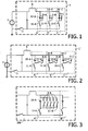
- Fig. 1 shows a prior art driver circuit arrangement.
- the driver circuit arrangement 1 comprises a connecting switch 3, which connects a power converter, schematically indicated by reference numeral 5, to an external source of energy 7.
- the arrangement 1 further comprises three subsystems A, B and C, each of which comprises an electrical device 9, an energy storage device 10 and a switch 11.
- the prior art driver circuit arrangement as shown in Fig. 1 is connectable to a source of electrical energy 7, such as a voltage source, e.g. a battery.
- a source of electrical energy 7 such as a voltage source, e.g. a battery.
- the circuit arrangement 1 comprises three subsystems A, B and C.
- Each subsystem A, B, C comprises an electrical device, an energy storage device and a switch. Taking a look at the first subsystem A, this would work as follows:
- this subsystem A could be supplied with electrical energy from the source 7, and switch 11-A will be in a closed position. If desired, switches 11-B and 11-C may be in an open position, although this is not necessary.
- the device 9-A will now be supplied with energy from the energy source 7, while also energy source device 10-A will be supplied with energy.
- the device 9-A may, in principle, be any desired electrical device, but is preferably a simple device such as an LED, including an organic LED, and so on. For the present embodiment, the devices are taken to be LEDs.
- the energy storage device 10-A may for example be a capacitor.
- control device may deselect the first subsystem A, e.g. by opening the switch 11-A.
- the capacitor 10-A will start supplying the electrical device 9-A with electrical energy.
- the electrical device 9-A will be supplied with electrical energy even after disconnecting the device 9-A from the main source 7 of electrical energy. This reduces control over the functioning of the device 9-A. Similar considerations of course hold for the other subsystems B and C.
- Fig. 2 schematically shows a driver circuit arrangement according to the present invention. Similar parts are denoted by the same reference numerals.
- the driver circuit arrangement 1' again comprises a connecting switch 3 that connects a power converter 5 to a source 7 of electrical energy.
- the driver circuit arrangement 1' again comprises 3 subsystems A', B' and C'. Of course, any other plural number of subsystems, such as 2, or 4, 5, etc., is also possible. Note that in particular very large numbers of electrical subsystems are contemplated, such as large numbers of LEDs or pixels in a display.
- Each subsystem, e.g. subsystem A' comprises an electrical device, an energy storage device, a switch and a subswitch, for example 9-A, 10-A, 11-A and 13-A, respectively.
- the connecting switch 3 may also be some other means of connecting the driver circuit arrangement 1 to the source of energy 7, such as an electrical plug etc.
- the power converter 5 has only been indicated schematically. It may comprise a buck converter, a boost converter, and a combination thereof, etc. It is also possible to provide such a power converter 5 as an external device, such as being a part of the source of electrical energy 7.
- the driver circuit arrangement 1' may e.g. function as follows.
- An external control unit (not shown), which may also be comprised in the driver circuit arrangement, in the form of an IC, may e.g. select the first subsystem A' to be supplied with energy from the source 7.
- the control unit may for example close the switch 11-A, while the other switches, 11-B and 11-C, may either be open or closed.
- the control unit may further control the subswitch 13-A, for example to be in a closed position.
- the device 9-A will be supplied with energy from the source 7, while also the energy storage device 10-A will be supplied with energy.
- the control unit deselects the first subsystem A', e.g.
- the energy storage device 10-A may still provide energy to the electrical device 9-A if the subswitch 13-A is closed.
- the control unit (not shown) may still control energy flow to the electrical device 9-A by controlling the position of the subswitch 13-A. This may be performed in e.g. the pulse width modulation mode, or by simply keeping the subswitch 13-A closed until a certain amount of energy has flown from the energy storage device 10-A.
- Another subsystem, B' or C' may be selected.
- the selection of A', B' and C' may be completely independent of each other.
- a big advantage of the driver circuit arrangement 1' according to the present invention is that the control unit may still control the energy flow to the electrical devices, even when the main flow of energy from the source 7 of electrical energy to the electrical devices 9-A has been interrupted by the switch 11-A.
- the present invention has particular advantages when the electrical device 9-A, B, C, is a more complex device then the simple devices shown in Fig. 2 . All this will be discussed in the following embodiment.
- Fig. 3 diagrammatically shows a driver circuit arrangement 100 according to another embodiment of the present invention.
- the arrangement 100 comprises a subsystem A" comprising a large number of LEDs 9-A, an energy storage device 10-A, a switch 11-A and a large number of subswitches 13-A.
- the circuit arrangement 100 comprises more subsystems B", . «, which have not been indicated any further.
- the subsystem A" comprises a single capacitor 10-A and five LEDs, each with a separate subswitch 13-A.
- each of the electrical "subdevices" or LEDs 9-A may be controlled separately, by a control unit (not shown here). This allows optimum control over the total performance of the circuit arrangement 100. It is even possible to provide each electrical device 9-A with its own energy storage device 10-A. It is furthermore possible to make the circuit arrangement of the subsystem A" even more complex by providing a combination of series and parallel connections of electrical devices, or even more complexly connected devices 9-A.
- the electrical devices 9-A may for example be LEDs, although any other electrical device, such as lamps, LCD pixels, traffic lights, etc., are also possible. Taking for example five differently colored LEDs that in combination are able to emit white light, each subsystem A", B", etc. may form a single light emitting element of a display or the like. In that case, when building an image on the display, each light emitting element, or subsystem, may be controlled subsequently, by correspondingly switching the switches 11-A, 11-B etc. When in the meantime, i.e.
- the setting of the devices 9-A in the subsystem A" may still be changed by accordingly controlling the subswitches 13-A.
- the control unit (not shown) may decrease the pulse width with which the subswitches 30-A are closed, or may alternatively open those subswitches 13-A. It goes without saying that a similar control is exerted over the corresponding subswitches etc. in subsystem B", etc.
Landscapes
- Led Devices (AREA)
- Control Of Indicators Other Than Cathode Ray Tubes (AREA)
- Electronic Switches (AREA)
- Dc-Dc Converters (AREA)
Priority Applications (1)
| Application Number | Priority Date | Filing Date | Title |
|---|---|---|---|
| EP06809462A EP1935085B1 (en) | 2005-10-05 | 2006-10-02 | Driver circuit arrangement |
Applications Claiming Priority (3)
| Application Number | Priority Date | Filing Date | Title |
|---|---|---|---|
| EP05109219 | 2005-10-05 | ||
| EP06809462A EP1935085B1 (en) | 2005-10-05 | 2006-10-02 | Driver circuit arrangement |
| PCT/IB2006/053581 WO2007039862A2 (en) | 2005-10-05 | 2006-10-02 | Driver circuit arrangement |
Publications (2)
| Publication Number | Publication Date |
|---|---|
| EP1935085A2 EP1935085A2 (en) | 2008-06-25 |
| EP1935085B1 true EP1935085B1 (en) | 2012-03-28 |
Family
ID=37816578
Family Applications (1)
| Application Number | Title | Priority Date | Filing Date |
|---|---|---|---|
| EP06809462A Active EP1935085B1 (en) | 2005-10-05 | 2006-10-02 | Driver circuit arrangement |
Country Status (7)
| Country | Link |
|---|---|
| US (1) | US7893661B2 (enExample) |
| EP (1) | EP1935085B1 (enExample) |
| JP (1) | JP4971338B2 (enExample) |
| CN (1) | CN101278469B (enExample) |
| AT (1) | ATE551769T1 (enExample) |
| ES (1) | ES2384886T3 (enExample) |
| WO (1) | WO2007039862A2 (enExample) |
Families Citing this family (34)
| Publication number | Priority date | Publication date | Assignee | Title |
|---|---|---|---|---|
| US20050259424A1 (en) * | 2004-05-18 | 2005-11-24 | Zampini Thomas L Ii | Collimating and controlling light produced by light emitting diodes |
| US7766511B2 (en) * | 2006-04-24 | 2010-08-03 | Integrated Illumination Systems | LED light fixture |
| US7729941B2 (en) | 2006-11-17 | 2010-06-01 | Integrated Illumination Systems, Inc. | Apparatus and method of using lighting systems to enhance brand recognition |
| US8742686B2 (en) * | 2007-09-24 | 2014-06-03 | Integrated Illumination Systems, Inc. | Systems and methods for providing an OEM level networked lighting system |
| JP5519518B2 (ja) * | 2007-11-07 | 2014-06-11 | コーニンクレッカ フィリップス エヌ ヴェ | 電源回路 |
| US8255487B2 (en) * | 2008-05-16 | 2012-08-28 | Integrated Illumination Systems, Inc. | Systems and methods for communicating in a lighting network |
| US8585245B2 (en) | 2009-04-23 | 2013-11-19 | Integrated Illumination Systems, Inc. | Systems and methods for sealing a lighting fixture |
| EP2481268A1 (en) * | 2009-09-24 | 2012-08-01 | Koninklijke Philips Electronics N.V. | Electronic textile with local energy supply devices |
| JP2013544011A (ja) * | 2010-10-24 | 2013-12-09 | マイクロセミ コーポレィション | Ledストリングドライバのための同期制御 |
| US9614452B2 (en) | 2010-10-24 | 2017-04-04 | Microsemi Corporation | LED driving arrangement with reduced current spike |
| US9066381B2 (en) | 2011-03-16 | 2015-06-23 | Integrated Illumination Systems, Inc. | System and method for low level dimming |
| DE102011015282B4 (de) | 2011-03-28 | 2022-03-10 | Austriamicrosystems Ag | Gesteuerte Versorgungsschaltung |
| US11917740B2 (en) | 2011-07-26 | 2024-02-27 | Hunter Industries, Inc. | Systems and methods for providing power and data to devices |
| US20150237700A1 (en) | 2011-07-26 | 2015-08-20 | Hunter Industries, Inc. | Systems and methods to control color and brightness of lighting devices |
| US8710770B2 (en) | 2011-07-26 | 2014-04-29 | Hunter Industries, Inc. | Systems and methods for providing power and data to lighting devices |
| US9609720B2 (en) | 2011-07-26 | 2017-03-28 | Hunter Industries, Inc. | Systems and methods for providing power and data to lighting devices |
| US10874003B2 (en) | 2011-07-26 | 2020-12-22 | Hunter Industries, Inc. | Systems and methods for providing power and data to devices |
| US9521725B2 (en) | 2011-07-26 | 2016-12-13 | Hunter Industries, Inc. | Systems and methods for providing power and data to lighting devices |
| US8894437B2 (en) | 2012-07-19 | 2014-11-25 | Integrated Illumination Systems, Inc. | Systems and methods for connector enabling vertical removal |
| DE102012108965B4 (de) | 2012-09-24 | 2014-08-14 | Exscitron Gmbh | Stromquelle mit verbesserter Dimmvorrichtung |
| US9379578B2 (en) | 2012-11-19 | 2016-06-28 | Integrated Illumination Systems, Inc. | Systems and methods for multi-state power management |
| US9420665B2 (en) | 2012-12-28 | 2016-08-16 | Integration Illumination Systems, Inc. | Systems and methods for continuous adjustment of reference signal to control chip |
| US9485814B2 (en) | 2013-01-04 | 2016-11-01 | Integrated Illumination Systems, Inc. | Systems and methods for a hysteresis based driver using a LED as a voltage reference |
| GB2515805A (en) * | 2013-07-05 | 2015-01-07 | Bae Systems Plc | Improvements in and relating to displays and light sources for displays |
| WO2015001363A1 (en) | 2013-07-05 | 2015-01-08 | Bae Systems Plc | Improvements in and relating to displays and light sources for displays |
| US9491815B2 (en) | 2013-10-02 | 2016-11-08 | Microsemi Corporation | LED luminaire driving circuit and method |
| US20170104350A1 (en) * | 2014-06-18 | 2017-04-13 | Koninklijke Philips N.V. | Device and method for controlling a plurality of cells of a battery |
| US10228711B2 (en) | 2015-05-26 | 2019-03-12 | Hunter Industries, Inc. | Decoder systems and methods for irrigation control |
| US10918030B2 (en) | 2015-05-26 | 2021-02-16 | Hunter Industries, Inc. | Decoder systems and methods for irrigation control |
| US10030844B2 (en) | 2015-05-29 | 2018-07-24 | Integrated Illumination Systems, Inc. | Systems, methods and apparatus for illumination using asymmetrical optics |
| US10060599B2 (en) | 2015-05-29 | 2018-08-28 | Integrated Illumination Systems, Inc. | Systems, methods and apparatus for programmable light fixtures |
| US10801714B1 (en) | 2019-10-03 | 2020-10-13 | CarJamz, Inc. | Lighting device |
| US12416908B2 (en) | 2022-12-29 | 2025-09-16 | Integrated Illumination Systems, Inc. | Systems and methods for manufacturing light fixtures |
| US12297996B2 (en) | 2023-02-16 | 2025-05-13 | Integrated Illumination Systems, Inc. | Cove light fixture with hidden integrated air return |
Family Cites Families (12)
| Publication number | Priority date | Publication date | Assignee | Title |
|---|---|---|---|---|
| DE4022166A1 (de) | 1990-07-12 | 1992-01-16 | Siemens Ag | Integrierbare, verlustarme vielfach-led-ansteuerung |
| JPH05236673A (ja) * | 1992-02-25 | 1993-09-10 | Matsushita Electric Works Ltd | 所在位置表示装置 |
| US6421600B1 (en) * | 1994-05-05 | 2002-07-16 | H. R. Ross Industries, Inc. | Roadway-powered electric vehicle system having automatic guidance and demand-based dispatch features |
| US5936599A (en) | 1995-01-27 | 1999-08-10 | Reymond; Welles | AC powered light emitting diode array circuits for use in traffic signal displays |
| US6618031B1 (en) | 1999-02-26 | 2003-09-09 | Three-Five Systems, Inc. | Method and apparatus for independent control of brightness and color balance in display and illumination systems |
| US6369525B1 (en) * | 2000-11-21 | 2002-04-09 | Philips Electronics North America | White light-emitting-diode lamp driver based on multiple output converter with output current mode control |
| US6452814B1 (en) | 2001-09-19 | 2002-09-17 | Technical Witts, Inc. | Zero voltage switching cells for power converters |
| JP2003203766A (ja) * | 2002-01-07 | 2003-07-18 | Hitachi Ltd | エレクトロルミネッセンス表示装置の製造方法 |
| US6930893B2 (en) * | 2002-01-31 | 2005-08-16 | Vlt, Inc. | Factorized power architecture with point of load sine amplitude converters |
| WO2003081758A1 (fr) | 2002-03-26 | 2003-10-02 | Matsushita Electric Works, Ltd. | Convertisseur de puissance |
| JP4148746B2 (ja) * | 2002-10-08 | 2008-09-10 | 株式会社小糸製作所 | 点灯回路 |
| JP2005050761A (ja) * | 2003-07-31 | 2005-02-24 | Epsel:Kk | 照明制御装置 |
-
2006
- 2006-10-02 AT AT06809462T patent/ATE551769T1/de active
- 2006-10-02 EP EP06809462A patent/EP1935085B1/en active Active
- 2006-10-02 CN CN2006800369378A patent/CN101278469B/zh active Active
- 2006-10-02 US US12/089,236 patent/US7893661B2/en active Active
- 2006-10-02 WO PCT/IB2006/053581 patent/WO2007039862A2/en not_active Ceased
- 2006-10-02 ES ES06809462T patent/ES2384886T3/es active Active
- 2006-10-02 JP JP2008534125A patent/JP4971338B2/ja active Active
Also Published As
| Publication number | Publication date |
|---|---|
| CN101278469B (zh) | 2012-11-14 |
| CN101278469A (zh) | 2008-10-01 |
| JP2009512264A (ja) | 2009-03-19 |
| ES2384886T3 (es) | 2012-07-13 |
| ATE551769T1 (de) | 2012-04-15 |
| EP1935085A2 (en) | 2008-06-25 |
| WO2007039862A2 (en) | 2007-04-12 |
| US7893661B2 (en) | 2011-02-22 |
| JP4971338B2 (ja) | 2012-07-11 |
| WO2007039862A3 (en) | 2007-07-05 |
| US20080272743A1 (en) | 2008-11-06 |
Similar Documents
| Publication | Publication Date | Title |
|---|---|---|
| EP1935085B1 (en) | Driver circuit arrangement | |
| US20110025230A1 (en) | Driver device for leds | |
| US7911151B2 (en) | Single driver for multiple light emitting diodes | |
| US8378591B2 (en) | Light output device | |
| US9204509B2 (en) | System and apparatus for a dual LED light bar | |
| JP2009004483A (ja) | 発光ダイオード駆動回路 | |
| CN102421230A (zh) | 一种led灯色彩调节驱动器 | |
| KR102633097B1 (ko) | 통합 전원 공급 장치를 구비한 led 장치 및 이를 이용하는 방법 | |
| JP2011108799A (ja) | 発光装置、並びに、当該発光装置を備えた照明装置及び表示装置 | |
| CN102316647A (zh) | 一种led灯色温调节驱动器 | |
| US8779672B2 (en) | Driver circuit for light-emitting diodes and method | |
| CN108966408B (zh) | 由多个光发射器共用的电流源 | |
| CN113271700A (zh) | 灯光系统 | |
| JP2011113684A (ja) | 発光装置、並びに、当該発光装置を備えた照明装置及び表示装置 | |
| CN201550335U (zh) | 发光二极管驱动电路及白平衡系统 | |
| US7683861B2 (en) | Arrangement for driving LED lighting sources | |
| US11974368B1 (en) | Light control systems, methods, devices, and uses thereof | |
| CN202261958U (zh) | 一种led灯色彩调节驱动器 | |
| JP2009181950A (ja) | 照明装置 | |
| CN108337762B (zh) | 控制电路和led照明装置 | |
| WO2025181382A1 (en) | Luminous device with several types of light sources | |
| KR102229510B1 (ko) | 다채널 led 램프 밝기 제어 회로 | |
| CN201029012Y (zh) | Led电路 | |
| KR100859138B1 (ko) | 커플 led 표시 장치 | |
| KR20160095773A (ko) | 조명 디바이스 |
Legal Events
| Date | Code | Title | Description |
|---|---|---|---|
| PUAI | Public reference made under article 153(3) epc to a published international application that has entered the european phase |
Free format text: ORIGINAL CODE: 0009012 |
|
| 17P | Request for examination filed |
Effective date: 20080506 |
|
| AK | Designated contracting states |
Kind code of ref document: A2 Designated state(s): AT BE BG CH CY CZ DE DK EE ES FI FR GB GR HU IE IS IT LI LT LU LV MC NL PL PT RO SE SI SK TR |
|
| 17Q | First examination report despatched |
Effective date: 20110524 |
|
| GRAP | Despatch of communication of intention to grant a patent |
Free format text: ORIGINAL CODE: EPIDOSNIGR1 |
|
| DAX | Request for extension of the european patent (deleted) | ||
| GRAS | Grant fee paid |
Free format text: ORIGINAL CODE: EPIDOSNIGR3 |
|
| GRAA | (expected) grant |
Free format text: ORIGINAL CODE: 0009210 |
|
| AK | Designated contracting states |
Kind code of ref document: B1 Designated state(s): AT BE BG CH CY CZ DE DK EE ES FI FR GB GR HU IE IS IT LI LT LU LV MC NL PL PT RO SE SI SK TR |
|
| REG | Reference to a national code |
Ref country code: GB Ref legal event code: FG4D |
|
| REG | Reference to a national code |
Ref country code: CH Ref legal event code: EP |
|
| REG | Reference to a national code |
Ref country code: AT Ref legal event code: REF Ref document number: 551769 Country of ref document: AT Kind code of ref document: T Effective date: 20120415 |
|
| REG | Reference to a national code |
Ref country code: IE Ref legal event code: FG4D |
|
| REG | Reference to a national code |
Ref country code: DE Ref legal event code: R096 Ref document number: 602006028511 Country of ref document: DE Effective date: 20120606 |
|
| REG | Reference to a national code |
Ref country code: ES Ref legal event code: FG2A Ref document number: 2384886 Country of ref document: ES Kind code of ref document: T3 Effective date: 20120713 |
|
| REG | Reference to a national code |
Ref country code: NL Ref legal event code: VDEP Effective date: 20120328 |
|
| PG25 | Lapsed in a contracting state [announced via postgrant information from national office to epo] |
Ref country code: LT Free format text: LAPSE BECAUSE OF FAILURE TO SUBMIT A TRANSLATION OF THE DESCRIPTION OR TO PAY THE FEE WITHIN THE PRESCRIBED TIME-LIMIT Effective date: 20120328 |
|
| LTIE | Lt: invalidation of european patent or patent extension |
Effective date: 20120328 |
|
| PG25 | Lapsed in a contracting state [announced via postgrant information from national office to epo] |
Ref country code: GR Free format text: LAPSE BECAUSE OF FAILURE TO SUBMIT A TRANSLATION OF THE DESCRIPTION OR TO PAY THE FEE WITHIN THE PRESCRIBED TIME-LIMIT Effective date: 20120629 Ref country code: LV Free format text: LAPSE BECAUSE OF FAILURE TO SUBMIT A TRANSLATION OF THE DESCRIPTION OR TO PAY THE FEE WITHIN THE PRESCRIBED TIME-LIMIT Effective date: 20120328 Ref country code: FI Free format text: LAPSE BECAUSE OF FAILURE TO SUBMIT A TRANSLATION OF THE DESCRIPTION OR TO PAY THE FEE WITHIN THE PRESCRIBED TIME-LIMIT Effective date: 20120328 |
|
| REG | Reference to a national code |
Ref country code: AT Ref legal event code: MK05 Ref document number: 551769 Country of ref document: AT Kind code of ref document: T Effective date: 20120328 |
|
| PG25 | Lapsed in a contracting state [announced via postgrant information from national office to epo] |
Ref country code: CY Free format text: LAPSE BECAUSE OF FAILURE TO SUBMIT A TRANSLATION OF THE DESCRIPTION OR TO PAY THE FEE WITHIN THE PRESCRIBED TIME-LIMIT Effective date: 20120328 |
|
| PG25 | Lapsed in a contracting state [announced via postgrant information from national office to epo] |
Ref country code: PL Free format text: LAPSE BECAUSE OF FAILURE TO SUBMIT A TRANSLATION OF THE DESCRIPTION OR TO PAY THE FEE WITHIN THE PRESCRIBED TIME-LIMIT Effective date: 20120328 Ref country code: EE Free format text: LAPSE BECAUSE OF FAILURE TO SUBMIT A TRANSLATION OF THE DESCRIPTION OR TO PAY THE FEE WITHIN THE PRESCRIBED TIME-LIMIT Effective date: 20120328 Ref country code: IS Free format text: LAPSE BECAUSE OF FAILURE TO SUBMIT A TRANSLATION OF THE DESCRIPTION OR TO PAY THE FEE WITHIN THE PRESCRIBED TIME-LIMIT Effective date: 20120728 Ref country code: CZ Free format text: LAPSE BECAUSE OF FAILURE TO SUBMIT A TRANSLATION OF THE DESCRIPTION OR TO PAY THE FEE WITHIN THE PRESCRIBED TIME-LIMIT Effective date: 20120328 Ref country code: SI Free format text: LAPSE BECAUSE OF FAILURE TO SUBMIT A TRANSLATION OF THE DESCRIPTION OR TO PAY THE FEE WITHIN THE PRESCRIBED TIME-LIMIT Effective date: 20120328 Ref country code: RO Free format text: LAPSE BECAUSE OF FAILURE TO SUBMIT A TRANSLATION OF THE DESCRIPTION OR TO PAY THE FEE WITHIN THE PRESCRIBED TIME-LIMIT Effective date: 20120328 Ref country code: BE Free format text: LAPSE BECAUSE OF FAILURE TO SUBMIT A TRANSLATION OF THE DESCRIPTION OR TO PAY THE FEE WITHIN THE PRESCRIBED TIME-LIMIT Effective date: 20120328 Ref country code: SE Free format text: LAPSE BECAUSE OF FAILURE TO SUBMIT A TRANSLATION OF THE DESCRIPTION OR TO PAY THE FEE WITHIN THE PRESCRIBED TIME-LIMIT Effective date: 20120328 |
|
| PG25 | Lapsed in a contracting state [announced via postgrant information from national office to epo] |
Ref country code: SK Free format text: LAPSE BECAUSE OF FAILURE TO SUBMIT A TRANSLATION OF THE DESCRIPTION OR TO PAY THE FEE WITHIN THE PRESCRIBED TIME-LIMIT Effective date: 20120328 Ref country code: PT Free format text: LAPSE BECAUSE OF FAILURE TO SUBMIT A TRANSLATION OF THE DESCRIPTION OR TO PAY THE FEE WITHIN THE PRESCRIBED TIME-LIMIT Effective date: 20120730 |
|
| REG | Reference to a national code |
Ref country code: DE Ref legal event code: R097 Ref document number: 602006028511 Country of ref document: DE |
|
| PG25 | Lapsed in a contracting state [announced via postgrant information from national office to epo] |
Ref country code: DK Free format text: LAPSE BECAUSE OF FAILURE TO SUBMIT A TRANSLATION OF THE DESCRIPTION OR TO PAY THE FEE WITHIN THE PRESCRIBED TIME-LIMIT Effective date: 20120328 Ref country code: AT Free format text: LAPSE BECAUSE OF FAILURE TO SUBMIT A TRANSLATION OF THE DESCRIPTION OR TO PAY THE FEE WITHIN THE PRESCRIBED TIME-LIMIT Effective date: 20120328 Ref country code: NL Free format text: LAPSE BECAUSE OF FAILURE TO SUBMIT A TRANSLATION OF THE DESCRIPTION OR TO PAY THE FEE WITHIN THE PRESCRIBED TIME-LIMIT Effective date: 20120328 |
|
| PLBE | No opposition filed within time limit |
Free format text: ORIGINAL CODE: 0009261 |
|
| STAA | Information on the status of an ep patent application or granted ep patent |
Free format text: STATUS: NO OPPOSITION FILED WITHIN TIME LIMIT |
|
| 26N | No opposition filed |
Effective date: 20130103 |
|
| REG | Reference to a national code |
Ref country code: DE Ref legal event code: R081 Ref document number: 602006028511 Country of ref document: DE Owner name: PHILIPS INTELLECTUAL PROPERTY & STANDARDS GMBH, DE Free format text: FORMER OWNER: PHILIPS INTELLECTUAL PROPERTY &, KONINKLIJKE PHILIPS ELECTRONICS, , NL Effective date: 20130123 Ref country code: DE Ref legal event code: R081 Ref document number: 602006028511 Country of ref document: DE Owner name: PHILIPS DEUTSCHLAND GMBH, DE Free format text: FORMER OWNER: PHILIPS INTELLECTUAL PROPERTY &, KONINKLIJKE PHILIPS ELECTRONICS, , NL Effective date: 20130123 Ref country code: DE Ref legal event code: R081 Ref document number: 602006028511 Country of ref document: DE Owner name: PHILIPS GMBH, DE Free format text: FORMER OWNER: PHILIPS INTELLECTUAL PROPERTY &, KONINKLIJKE PHILIPS ELECTRONICS, , NL Effective date: 20130123 Ref country code: DE Ref legal event code: R081 Ref document number: 602006028511 Country of ref document: DE Owner name: PHILIPS GMBH, DE Free format text: FORMER OWNERS: PHILIPS INTELLECTUAL PROPERTY & STANDARDS GMBH, 20099 HAMBURG, DE; KONINKLIJKE PHILIPS ELECTRONICS N.V., EINDHOVEN, NL Effective date: 20130123 Ref country code: DE Ref legal event code: R081 Ref document number: 602006028511 Country of ref document: DE Owner name: PHILIPS LIGHTING HOLDING B.V., NL Free format text: FORMER OWNERS: PHILIPS INTELLECTUAL PROPERTY & STANDARDS GMBH, 20099 HAMBURG, DE; KONINKLIJKE PHILIPS ELECTRONICS N.V., EINDHOVEN, NL Effective date: 20130123 |
|
| REG | Reference to a national code |
Ref country code: DE Ref legal event code: R097 Ref document number: 602006028511 Country of ref document: DE Effective date: 20130103 |
|
| PG25 | Lapsed in a contracting state [announced via postgrant information from national office to epo] |
Ref country code: MC Free format text: LAPSE BECAUSE OF NON-PAYMENT OF DUE FEES Effective date: 20121031 |
|
| REG | Reference to a national code |
Ref country code: CH Ref legal event code: PL |
|
| REG | Reference to a national code |
Ref country code: IE Ref legal event code: MM4A |
|
| PG25 | Lapsed in a contracting state [announced via postgrant information from national office to epo] |
Ref country code: LI Free format text: LAPSE BECAUSE OF NON-PAYMENT OF DUE FEES Effective date: 20121031 Ref country code: CH Free format text: LAPSE BECAUSE OF NON-PAYMENT OF DUE FEES Effective date: 20121031 Ref country code: IE Free format text: LAPSE BECAUSE OF NON-PAYMENT OF DUE FEES Effective date: 20121002 Ref country code: BG Free format text: LAPSE BECAUSE OF FAILURE TO SUBMIT A TRANSLATION OF THE DESCRIPTION OR TO PAY THE FEE WITHIN THE PRESCRIBED TIME-LIMIT Effective date: 20120628 |
|
| REG | Reference to a national code |
Ref country code: ES Ref legal event code: PC2A Owner name: KONINKLIJKE PHILIPS N.V. Effective date: 20140220 |
|
| PG25 | Lapsed in a contracting state [announced via postgrant information from national office to epo] |
Ref country code: TR Free format text: LAPSE BECAUSE OF FAILURE TO SUBMIT A TRANSLATION OF THE DESCRIPTION OR TO PAY THE FEE WITHIN THE PRESCRIBED TIME-LIMIT Effective date: 20120328 |
|
| REG | Reference to a national code |
Ref country code: DE Ref legal event code: R081 Ref document number: 602006028511 Country of ref document: DE Owner name: PHILIPS GMBH, DE Free format text: FORMER OWNER: PHILIPS INTELLECTUAL PROPERTY & STANDARDS GMBH, 52066 AACHEN, DE Effective date: 20140331 Ref country code: DE Ref legal event code: R081 Ref document number: 602006028511 Country of ref document: DE Owner name: PHILIPS LIGHTING HOLDING B.V., NL Free format text: FORMER OWNER: PHILIPS INTELLECTUAL PROPERTY & STANDARDS GMBH, 52066 AACHEN, DE Effective date: 20140331 Ref country code: DE Ref legal event code: R081 Ref document number: 602006028511 Country of ref document: DE Owner name: PHILIPS DEUTSCHLAND GMBH, DE Free format text: FORMER OWNER: PHILIPS INTELLECTUAL PROPERTY & STANDARDS GMBH, 52066 AACHEN, DE Effective date: 20140331 |
|
| PG25 | Lapsed in a contracting state [announced via postgrant information from national office to epo] |
Ref country code: LU Free format text: LAPSE BECAUSE OF NON-PAYMENT OF DUE FEES Effective date: 20121002 |
|
| PG25 | Lapsed in a contracting state [announced via postgrant information from national office to epo] |
Ref country code: HU Free format text: LAPSE BECAUSE OF FAILURE TO SUBMIT A TRANSLATION OF THE DESCRIPTION OR TO PAY THE FEE WITHIN THE PRESCRIBED TIME-LIMIT Effective date: 20061002 |
|
| REG | Reference to a national code |
Ref country code: FR Ref legal event code: CD Owner name: PHILIPS INTELLECTUAL PROPERTY & STANDARDS GMBH, DE Effective date: 20141126 Ref country code: FR Ref legal event code: CA Effective date: 20141126 Ref country code: FR Ref legal event code: CD Owner name: KONINKLIJKE PHILIPS ELECTRONICS N.V., NL Effective date: 20141126 |
|
| REG | Reference to a national code |
Ref country code: DE Ref legal event code: R081 Ref document number: 602006028511 Country of ref document: DE Owner name: PHILIPS GMBH, DE Free format text: FORMER OWNER: PHILIPS DEUTSCHLAND GMBH, 20099 HAMBURG, DE Ref country code: DE Ref legal event code: R081 Ref document number: 602006028511 Country of ref document: DE Owner name: PHILIPS LIGHTING HOLDING B.V., NL Free format text: FORMER OWNER: PHILIPS DEUTSCHLAND GMBH, 20099 HAMBURG, DE |
|
| REG | Reference to a national code |
Ref country code: FR Ref legal event code: PLFP Year of fee payment: 10 |
|
| REG | Reference to a national code |
Ref country code: FR Ref legal event code: PLFP Year of fee payment: 11 |
|
| REG | Reference to a national code |
Ref country code: GB Ref legal event code: 732E Free format text: REGISTERED BETWEEN 20161006 AND 20161012 |
|
| REG | Reference to a national code |
Ref country code: DE Ref legal event code: R081 Ref document number: 602006028511 Country of ref document: DE Owner name: SIGNIFY HOLDING B.V., NL Free format text: FORMER OWNER: PHILIPS GMBH, 20099 HAMBURG, DE Ref country code: DE Ref legal event code: R081 Ref document number: 602006028511 Country of ref document: DE Owner name: PHILIPS LIGHTING HOLDING B.V., NL Free format text: FORMER OWNER: PHILIPS GMBH, 20099 HAMBURG, DE |
|
| REG | Reference to a national code |
Ref country code: FR Ref legal event code: PLFP Year of fee payment: 12 |
|
| REG | Reference to a national code |
Ref country code: FR Ref legal event code: PLFP Year of fee payment: 13 |
|
| REG | Reference to a national code |
Ref country code: ES Ref legal event code: PC2A Owner name: PHILIPS LIGHTING HOLDING B.V. Effective date: 20181221 |
|
| REG | Reference to a national code |
Ref country code: ES Ref legal event code: PC2A Owner name: SIGNIFY HOLDING B.V. Effective date: 20201013 |
|
| REG | Reference to a national code |
Ref country code: DE Ref legal event code: R082 Ref document number: 602006028511 Country of ref document: DE Representative=s name: MEISSNER BOLTE PATENTANWAELTE RECHTSANWAELTE P, DE Ref country code: DE Ref legal event code: R081 Ref document number: 602006028511 Country of ref document: DE Owner name: SIGNIFY HOLDING B.V., NL Free format text: FORMER OWNER: PHILIPS LIGHTING HOLDING B.V., EINDHOVEN, NL |
|
| P01 | Opt-out of the competence of the unified patent court (upc) registered |
Effective date: 20230421 |
|
| PGFP | Annual fee paid to national office [announced via postgrant information from national office to epo] |
Ref country code: GB Payment date: 20241022 Year of fee payment: 19 |
|
| PGFP | Annual fee paid to national office [announced via postgrant information from national office to epo] |
Ref country code: FR Payment date: 20241025 Year of fee payment: 19 |
|
| PGFP | Annual fee paid to national office [announced via postgrant information from national office to epo] |
Ref country code: IT Payment date: 20241022 Year of fee payment: 19 Ref country code: ES Payment date: 20241118 Year of fee payment: 19 |
|
| PGFP | Annual fee paid to national office [announced via postgrant information from national office to epo] |
Ref country code: DE Payment date: 20241227 Year of fee payment: 19 |