EP1932987B1 - Stellelementanordnung in einem Kraftfahrzeug - Google Patents
Stellelementanordnung in einem Kraftfahrzeug Download PDFInfo
- Publication number
- EP1932987B1 EP1932987B1 EP07019514A EP07019514A EP1932987B1 EP 1932987 B1 EP1932987 B1 EP 1932987B1 EP 07019514 A EP07019514 A EP 07019514A EP 07019514 A EP07019514 A EP 07019514A EP 1932987 B1 EP1932987 B1 EP 1932987B1
- Authority
- EP
- European Patent Office
- Prior art keywords
- actuator element
- blocking
- arrangement
- end position
- cable
- Prior art date
- Legal status (The legal status is an assumption and is not a legal conclusion. Google has not performed a legal analysis and makes no representation as to the accuracy of the status listed.)
- Not-in-force
Links
- 230000000903 blocking effect Effects 0.000 claims abstract description 98
- 239000000725 suspension Substances 0.000 claims description 5
- 230000000712 assembly Effects 0.000 description 1
- 238000000429 assembly Methods 0.000 description 1
- 238000005452 bending Methods 0.000 description 1
- 230000002457 bidirectional effect Effects 0.000 description 1
- 238000005516 engineering process Methods 0.000 description 1
- 238000005494 tarnishing Methods 0.000 description 1
Images



Classifications
-
- E—FIXED CONSTRUCTIONS
- E05—LOCKS; KEYS; WINDOW OR DOOR FITTINGS; SAFES
- E05B—LOCKS; ACCESSORIES THEREFOR; HANDCUFFS
- E05B77/00—Vehicle locks characterised by special functions or purposes
- E05B77/36—Noise prevention; Anti-rattling means
-
- E—FIXED CONSTRUCTIONS
- E05—LOCKS; KEYS; WINDOW OR DOOR FITTINGS; SAFES
- E05B—LOCKS; ACCESSORIES THEREFOR; HANDCUFFS
- E05B79/00—Mounting or connecting vehicle locks or parts thereof
- E05B79/10—Connections between movable lock parts
- E05B79/20—Connections between movable lock parts using flexible connections, e.g. Bowden cables
-
- E—FIXED CONSTRUCTIONS
- E05—LOCKS; KEYS; WINDOW OR DOOR FITTINGS; SAFES
- E05B—LOCKS; ACCESSORIES THEREFOR; HANDCUFFS
- E05B81/00—Power-actuated vehicle locks
- E05B81/12—Power-actuated vehicle locks characterised by the function or purpose of the powered actuators
- E05B81/14—Power-actuated vehicle locks characterised by the function or purpose of the powered actuators operating on bolt detents, e.g. for unlatching the bolt
-
- G—PHYSICS
- G05—CONTROLLING; REGULATING
- G05G—CONTROL DEVICES OR SYSTEMS INSOFAR AS CHARACTERISED BY MECHANICAL FEATURES ONLY
- G05G5/00—Means for preventing, limiting or returning the movements of parts of a control mechanism, e.g. locking controlling member
- G05G5/04—Stops for limiting movement of members, e.g. adjustable stop
-
- E—FIXED CONSTRUCTIONS
- E05—LOCKS; KEYS; WINDOW OR DOOR FITTINGS; SAFES
- E05B—LOCKS; ACCESSORIES THEREFOR; HANDCUFFS
- E05B81/00—Power-actuated vehicle locks
- E05B81/24—Power-actuated vehicle locks characterised by constructional features of the actuator or the power transmission
- E05B81/25—Actuators mounted separately from the lock and controlling the lock functions through mechanical connections
Definitions
- the present invention relates to an actuator assembly in a motor vehicle having the features of the preamble of claim 1 and a motor vehicle lock with such an actuator assembly having the features of the preamble of claim 10.
- adjusting elements In a motor vehicle numerous manual and / or motorized adjustable elements are provided, which are referred to in the present case as adjusting elements.
- adjusting elements By way of example, the fields of application of motor vehicle locks, manual or motorized seat adjusters or window regulators and manually or motor-adjustable flaps, in particular tailgates, trunk lids, side doors or the like may be mentioned.
- Such an actuating element is usually part of a control element arrangement in question, which has a blocking arrangement in addition to the actuating element.
- the blocking arrangement ensures that the actuating element is blocked when reaching at least one predetermined end position. Such blocking often takes place via suitably arranged end stops. This ensures that the end positions of the actuating element can be approached with relatively high accuracy.
- an overcurrent shutdown can be realized in the end positions.
- the known actuator arrangement ( EP 0 811 101 B1 ), from which the invention proceeds, is part of a motor vehicle lock with the closing elements latch and pawl and with a lock mechanism.
- One of the lock functions here is a motor opening function, by means of which the pawl can be raised by a motor.
- a drive motor downstream actuator is provided which comes in the motor opening operation into engagement with the pawl and then runs against a stop.
- a disadvantage of the known actuator arrangement is the fact that the blocking of the actuator is connected to the stop with unwanted noise, which is seen by the user as a loss of comfort.
- the actuator of this further actuator assembly is the latch of the motor vehicle lock.
- the latch can be adjusted between two end positions - open position, closed position - and is blocked when reaching both end positions by means of a blocking arrangement.
- the blocking arrangement is equipped with a rubber-elastic buffer element to keep the noise when reaching the end positions low.
- the end positions of the actuating element are realized here in a variant via a tilt spring ( DE 20 2005 004 042 U1 ).
- the invention is based on the problem, the known actuator arrangement to design and further develop such that a blockage of the actuating element is connected in one or more end positions with a minimal noise.
- blocking forces can also be tensile forces, which are transferable via a rope blocking rope.
- the blocking cable here serves exclusively for blocking. This means that on the blocking rope no driving forces, but only blocking forces are transmitted.
- the elastic design of the blocking cable and / or the suspension of the locking cable on the adjusting element and / or on the abutment is the subject of claim 6.
- a motor vehicle lock is claimed, which is assigned to the realization of a lock function, a control element arrangement described above according to claim 1.
- each additional lock function is correspondingly assigned a further control element arrangement.
- the actuating element arrangement according to the invention is associated with the pawl, wherein the actuating element is preferably the pawl itself. It is further preferably provided that the rope-based blocking arrangement blocks the pawl in the end position "raising position". This arrangement is advantageously applicable both in the context of manual and motorized lifting of the pawl.
- the actuator assembly of the latch is assigned, wherein the actuator is preferably the latch itself and can be blocked in at least one of the end positions "open position" and "closed position” by the rope-based blocking arrangement.
- This arrangement is particularly advantageous in a motor-driven latch in the context of a Zuziehtosfunktion, but can also be used in a conventional, non-driven latch to reduce noise.
- a central locking arrangement is provided with a central locking lever, which is associated with an actuating element arrangement according to the invention.
- the actuator of the central locking lever itself.
- the achievement The two end positions of the central locking lever "central locking on” and “central locking off” is correspondingly associated with a low noise level.
- the actuator of the actuator assembly of the central locking lever, the anti-theft lever, the pawl or the lock latch of the motor vehicle lock can also be a drive element connected downstream of a drive motor, which drive element is coupled to the respective component.
- actuator assemblies are equipped with an adjustable actuator 1 and a blocking assembly 2, wherein the blocking assembly 2 blocks the actuator 1 upon reaching at least one predetermined end position.
- the illustrated actuating elements 1 are bidirectionally adjustable. However, the solution according to the invention can also be applied to unidirectionally adjustable adjusting elements 1.
- the blocking assembly 2 is designed as a rope-based blocking assembly 2 and an end position of the actuating element 1 associated blocking cable 3, which serves exclusively for blocking and this is fixed to a pivot point 4 on the actuating element 1 on the one hand and on an abutment 5 on the other ,
- the actuator 1 is pivotable about an actuator axis 6.
- the adjusting element 1 is displaceable along a longitudinal axis.
- the blocking of the actuating element 1 is realized by means of the rope-based blocking arrangement in only one end position.
- This end position shows Fig. 1 ,
- the blocking cable 3 is stretched, the adjusting element 1 can not be further in the direction indicated by the reference numeral 7, in Fig. 1 So turn to the left, adjust.
- An adjustment of the actuating element 1 in Fig. 1 to the right is possible.
- the blocking rope 3 is relaxed again.
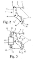
- Fig. 2 shows a preferred embodiment in which the actuating element 1 between a first, in Fig. 2 shown, end position and a second end position, not shown, is adjustable.
- two blocking cables 3, 3a are provided.
- the first end position associated with the blocking cable 3 is tensioned, resulting in a blocking of the actuating element 1 in the first end position.
- the second blocking cable 3a is tensioned, which leads to a blocking of the actuating element 1 in the second end position.
- FIG. 2 illustrated actuator 1 configured as a pivotable lever, wherein the first end position ( Fig. 2 ) associated blocking rope 3 on the one hand to a lever arm 8 of the actuating lever 1, there at the pivot point 4, and on the other hand is fixed to a thrust bearing 5.
- the blocking cable 3a assigned to the second end position is fixed on the one hand to a further lever arm 8a, there on the articulation point 4a, and on the other hand to another abutment 5a.
- the blocking cable 3a assigned to the second end position is also fixed to the one lever arm 8.
- the articulation points 4, 4a are always spaced as far as possible from the actuator axis 6, in order to reduce the blocking force as much as possible.
- both end positions of the actuating element 1 a single locking cable 3 is assigned.
- This single blocking cable 3 is fixed on the one hand to the adjusting element 1 and on the other hand to a suitably arranged abutment 5.
- An adjustment of the actuating element 1 in Fig. 4 on the right side causes the actuator 1, starting from the illustrated, first end position via a central position in which the locking cable 3 is not tensioned, is transferred to the second end position.
- the blocking cable 3 again tensions and blocks the actuating element 1.
- the blocking cable 3 and / or the suspension of the blocking cable 3 on the adjusting element 1 and / or on the abutment 5 is designed to be elastic or are.
- a Spring element is integrated.
- an embodiment in which the blocking cable 3 is designed to be elastic as such is particularly easy to implement.
- suspension of the locking cable 3 For the elastic embodiment of the suspension of the locking cable 3, a number of variants are also conceivable.
- a preferred variant is that the suspension is designed in the manner of a bending beam, which springs when reaching an end position.
- This stop 9 is equipped with a stop edge o. The like., against which the actuator 1 runs when reaching the first end position.
- the arrangement is such that the blocking cable 3 brakes the adjustment of the actuating element 1 before reaching the end position so that the tarnishing of the actuating element 1 takes place against the stop with only a low speed.
- the stop 9 is disposed beyond the respective end position and serves only for hedging, in particular for the case of a cable break.
- the actuating element 1 can be manually or motor-adjustable.
- the actuating element arrangement has a drive motor 10, which is drive-coupled to the actuating element 1.
- the drive motor 10 is coupled to the actuator 1 via a cable.
- the cable has two drive cables 11, 11a, which are fixed on the one hand to the control element 1 and on the other hand on the motor shaft 12 wound or unwound from the motor shaft 12.
- the one drive cable 11 and the one blocking cable 3 are sections of a one-piece rope, which is fixed at a position between the two cable ends on the lever arm 8 of the actuating element 1.
- Fig. 5 and 6 show an application for the above-described actuator assembly according to the invention, in a motor vehicle lock.
- the motor vehicle lock is here equipped with the closing elements latch 13 and pawl 14 and a lock mechanism, not shown.
- the motor vehicle lock is assigned to realize a lock function an actuator assembly with an actuator 1 and with a blocking assembly 2, wherein the blocking assembly 2 blocks the actuator 1 upon reaching at least one predetermined end position.
- the blocking arrangement 2 has, as described above, an end position of the actuating element 1 associated with a blocking rope 3, which is used exclusively for blocking and for this purpose on the one hand and on an abutment 5 on the other hand set on the actuator 1. All variants described above for the actuating element arrangement according to the invention are basically applicable in such a motor vehicle lock. Reference may be made to the above statements.
- the actuating element arrangement of the pawl 14 is assigned.
- the actuator 1 as shown, the pawl 14 itself. It may also be that the actuator 1 is drivingly coupled to the pawl 14 so that the actuator 1 then operates in the manner of a drive motor downstream drive element.
- the pawl 14 is here in the context of a motor opening function via a drive cable 11 of the in Fig. 5 presented incidence position in the in Fig. 6 illustrated Aushebewolf adjustable.
- the drive cable 11 is here wound on the motor shaft 12 of a drive motor 10 as described above.
- the pawl 14 is blocked by the rope-based blocking arrangement 2.
- the blocking cable 3 of the blocking arrangement 2 is fixed here on the pawl 14 on the one hand and on an abutment 5, here on the housing of the motor vehicle lock, on the other hand.
- the blocking cable 3 can also be fixed to a lever or the like coupled to the pawl 14.
- a further adjusting element arrangement is associated with the latch 13 of the motor vehicle lock.
- the actuating element 1 is preferably the latch 13 itself.
- the actuating element 1, similarly as mentioned above in connection with the pawl 14, is drivingly coupled to the latch 13.
- the latch 13 in its end positions “open position” ( Fig. 6 ) and “closed position” ( Fig. 5 ) Can be brought and in at least one of these end positions, here in both end positions, by means of the blocking assembly 2 'can be blocked.
- This embodiment basically corresponds to the in Fig. 4 illustrated embodiment (without stop). Reference may be made to the statements there.
- the actuator assembly can also be used in the context of the realization of other lock functions.
- An example of this is a central locking function.
- the motor vehicle lock on a central locking arrangement, not shown, with a central locking lever.
- the central locking lever is now associated with the actuating element assembly, wherein the actuating element 1 is again the central locking lever itself or wherein the actuating element 1 is drivingly coupled to the central locking lever.
- the central locking lever is adjustable between the first end position “central locking on” and the second end position "central locking off” and blockable in at least one of these end positions, preferably in both end positions, by means of the rope-based blocking arrangement 2.
- an actuator 1 according to Fig. 2, 3rd for use in which the blocking arrangement 2 comprises a first locking cable 3 and a second locking cable 3a.
- the central locking lever associated actuator assembly according to Fig. 4 (without stop) is designed. Again, reference may be made to the above statements.
- an anti-theft device is provided with an anti-theft lever to which the actuator assembly is assigned.
- the actuator 1 is preferably again the anti-theft lever itself.
- the actuator 1 may be coupled with the anti-theft lever but also drive technology.
- the anti-theft locking lever is adjustable between a first end position "anti-theft device” and a second end position "anti-theft device” and can be blocked in at least one of these end positions by means of the rope-based blocking arrangement 2.
- motor vehicle lock can of course have several lock functions such as central locking, anti-theft device o. The like., In the context of each of which an actuator assembly according to the invention can be used.
- the blocking rope as a wire rope, plastic rope, as a band o.
- the like. Be configured. In particular, it has a round or flat cross-section.
- actuator assembly In addition to the motor vehicle lock are other applications for the actuator assembly according to the invention preferably manual or motorized seat adjustments or windows and flaps, especially tailgates, trunk lid, side doors etc ..
Landscapes
- Physics & Mathematics (AREA)
- General Physics & Mathematics (AREA)
- Engineering & Computer Science (AREA)
- Automation & Control Theory (AREA)
- Lock And Its Accessories (AREA)
- Control Of Direct Current Motors (AREA)
Description
- Die vorliegende Erfindung betrifft eine Stellelementanordnung in einem Kraftfahrzeug mit den Merkmalen des Oberbegriffs von Anspruch 1 sowie ein Kraftfahrzeugschloß mit einer solchen Stellelementanordnung mit den Merkmalen des Oberbegriffs von Anspruch 10.
- In einem Kraftfahrzeug sind zahlreiche manuelle und/oder motorisch verstellbare Elemente vorgesehen, die vorliegend ganz allgemein als Stellelemente bezeichnet werden. Beispielhaft seien hier die Anwendungsbereiche der Kraftfahrzeugschlösser, der manuellen oder motorischen Sitzverstellungen oder Fensterheber sowie der manuell oder motorisch verstellbaren Klappen, insbesondere Heckklappen, Heckdeckel, Seitentüren o. dgl., genannt.
- Ein solches Stellelement ist in der Regel Bestandteil einer in Rede stehenden Stellelementanordnung, die neben dem Stellelement eine Blockieranordnung aufweist. Die Blockieranordnung sorgt dafür, daß das Stellelement bei Erreichen mindestens einer vorbestimmten Endstellung blockiert wird. Eine solche Blockierung erfolgt oftmals über in geeigneter Weise angeordnete Endanschläge. Damit ist gewährleistet, daß die Endstellungen des Stellelements mit relativ hoher Genauigkeit angefahren werden können. Bei der motorischen Verstellung des Stellelements mittels eines elektrischen Antriebsmotors kann in den Endstellungen eine Überstromabschaltung realisiert sein.
- Die bekannte Stellelementanordnung (
EP 0 811 101 B1 ), von der die Erfindung ausgeht, ist Bestandteil eines Krafifahrzeugschlosses mit den Schließelementen Schloßfalle und Sperrklinke und mit einer Schloßmechanik. Eine der Schloßfunktionen ist hier eine motorische Öffnungsfunktion, mittels der die Sperrklinke motorisch aushebbar ist. Hierfür ist ein einem Antriebsmotor nachgeschaltetes Stellelement vorgesehen, das beim motorischen Öffnungsvorgang in Eingriff mit der Sperrklinke kommt und anschließend gegen einen Anschlag läuft. - Nachteilig bei der bekannten Stellelementanordnung ist die Tatsache, daß die Blockierung des Stellelements an dem Anschlag mit ungewünschten Geräuschen verbunden ist, was vom Benutzer als Komforteinbuße gesehen wird.
- Das in der
EP 0 811 101 B1 dargestellte Kraftfahrzeugschloß zeigt noch eine weitere, in Rede stehende Stellelementanordnung. Das Stellelement dieser weiteren Stellelementanordnung ist die Schloßfalle des Kraftfahrzeugschlosses. Die Schloßfalle läßt sich zwischen zwei Endstellungen - Offenstellung, Schließstellung - verstellen und wird bei Erreichen beider Endstellungen mittels einer Blockieranordnung blockiert. Die Blockieranordnung ist mit einem gummielastischen Pufferelement ausgestattet, um die Geräuschentwicklung beim Erreichen der Endstellungen gering zu halten. - Bekannt ist ferner ein Kraftfahrzeugschloss mit einer Stellelementanordnung, bei der die für die Verstellung des Verstellelements erforderlich Antriebskraft über ein Seil übertragen wird. Die Endstellungen des Stellelements werden hier in einer Variante über eine Kippfeder realisiert (
DE 20 2005 004 042 U1 ). - Der Erfindung liegt das Problem zugrunde, die bekannte Stellelementanordnung derart auszugestalten und weiterzubilden, daß eine Blockierung des Stellelements in einer oder mehreren Endstellungen mit einer minimalen Geräuschentwicklung verbunden ist.
- Das obige Problem wird bei einer Stellelementanordnung mit den Merkmalen des Oberbegriffs von Anspruch 1 durch die Merkmale des kennzeichnenden Teils von Anspruch 1 gelöst.
- Wesentlich ist die Überlegung, die Blockieranordnung mit einem einer Endstellung des Stellelement zugeordneten Blockierseil auszustatten, das der Blockierung des Stellelements dient und hierfür am Stellelement einerseits und an einem Gegenlager andererseits festgelegt ist. Es ist also erkannt worden, daß Blockierkräfte auch Zugkräfte sein können, die über ein Seil- Blockierseil - übertragbar sind.
- Wesentlich ist ferner, daß das Blockierseil hier ausschließlich der Blockierung dient. Damit ist gemeint, daß über das Blockierseil keine Antriebskräfte, sondern ausschließlich Blockierkräfte übertragen werden.
- Besonders vorteilhaft bei der Ausstattung der Blockieranordnung mit einem Blockierseil ist die Tatsache, daß die Geräuschentwicklung bei der Blockierung besonders gering ist. Dies liegt zunächst daran, daß mit der Blockierung kein abruptes Auftreffen zweier Oberflächen verbunden ist. Ferner sorgt selbst eine geringe Elastizität des Blockierseils für eine erhebliche Geräuschdämpfung.
- Die elastische Auslegung des Blockierseils und/oder der Aufhängung des Blockierseils am Stellelement und/oder am Gegenlager ist Gegenstand von Anspruch 6.
- Nach einer bevorzugten Ausgestaltung gemäß Anspruch 10 wird ein Kraftfahrzeugschloß beansprucht, dem zur Realisierung einer Schloßfunktion eine oben beschriebene Stellelementanordnung nach Anspruch 1 zugeordnet ist. Dabei ist jeder weiteren Schloßfunktion entsprechend eine weitere Stellelementanordnung zugeordnet. Hinsichtlich der Ausgestaltung der Stellelementanordnung darf auf die obigen Ausführungen verwiesen werden.
- Bei der bevorzugten Ausgestaltung einer ersten Alternative von Anspruch 12 ist die erfindungsgemäße Stellelementanordnung der Sperrklinke zugeordnet, wobei das Stellelement vorzugsweise die Sperrklinke selbst ist. Dabei ist es weiter vorzugsweise vorgesehen, daß die seilbasierte Blockieranordnung die Sperrklinke in der Endstellung "Aushebestellung" blockiert. Diese Anordnung ist sowohl im Rahmen des manuellen als auch des motorischen Aushebens der Sperrklinke vorteilhaft anwendbar.
- Bei der bevorzugten Ausgestaltung einer zweiten Alternative von Anspruch 12 ist die Stellelementanordnung der Schloßfalle zugeordnet, wobei das Stellelement vorzugsweise die Schloßfalle selbst ist und in zumindest einer der Endstellungen "Offenstellung" und "Schließstellung" mittels der seilbasierten Blockieranordnung blockiert werden kann. Diese Anordnung ist insbesondere bei einer motorisch angetriebenen Schloßfalle im Rahmen einer Zuziehhilfsfunktion vorteilhaft, kann aber auch bei einer üblichen, nicht angetriebenen Schloßfalle zur Geräuschminderung eingesetzt werden.
- Bei der bevorzugten Ausgestaltung einer dritten Alternative von Anspruch 12 ist eine Zentralverriegelungsanordnung mit einem Zentralverriegelungshebel vorgesehen, dem eine erfindungsgemäße Stellelementanordnung zugeordnet ist. Dabei ist das Stellelement der Zentralverriegelungshebel selbst. Das Erreichen der beiden Endstellungen des Zentralverriegelungshebels "Zentralverriegelung Ein" und "Zentralverriegelung Aus" ist entsprechend mit einer geringen Geräuschentwicklung verbunden.
- Das gleiche gilt für einen Diebstahlsicherungshebel einer Diebstahlsicherungsanordnung des Kraftfahrzeugschlosses. Dies ist Gegenstand einer vierten Alternative von Anspruch 12.
- Bei den Ausgestaltungen gemäß Anspruch 12 ist das Stellelement der Stellelementanordnung der Zentralverriegelungshebel, der Diebstahlsicherungshebel, die Sperrklinke oder die Schloßfalle des Kraftfahrzeugschlosses. Grundsätzlich kann es sich bei dem Stellelement aber auch um ein einem Antriebsmotor nachgeschaltetes Antriebselement handeln, das antriebstechnisch mit der jeweiligen Komponente gekoppelt ist.
- Im folgenden wird die Erfindung anhand einer lediglich Ausführungsbeispiele darstellenden Zeichnung näher erläutert. In der Zeichnung zeigt
- Fig. 1
- eine erfindungsgemäße Stellelementanordnung in einer ersten Ausführungsform,
- Fig. 2
- eine erfindungsgemäße Stellelementanordnung in einer zweiten Ausführungsform,
- Fig. 3
- eine erfindungsgemäße Stellelementanordnung in einer dritten Ausführungsform,
- Fig. 4
- eine erfindungsgemäße Stellelementanordnung in einer vierten Ausführungsform,
- Fig. 5
- ein in der Schließstellung befindliches Kraftfahrzeugschloß mit erfindungsgemäßen Stellelementanordnungen und
- Fig. 6
- das Kraftfahrzeugschloß gemäß
Fig. 5 in der Offenstellung. - Die in der Zeichnung dargestellten verschiedenen Ausführungsformen einer erfindungsgemäßen Stellelementanordnung lassen sich auf beliebige verstellbare Elemente in einem Kraftfahrzeug anwenden. Die Darstellung des Anwendungsfalls eines Kraftfahrzeugschlosses in den
Fig. 5 und6 ist daher nicht beschränkend zu verstehen. - Alle dargestellten Ausführungsformen von Stellelementanordnungen sind mit einem verstellbaren Stellelement 1 und einer Blockieranordnung 2 ausgestattet, wobei die Blockieranordnung 2 das Stellelement 1 bei Erreichen mindestens einer vorbestimmten Endstellung blockiert.
- Die dargestellten Stellelemente 1 sind bidirektional verstellbar. Die erfindungsgemäße Lösung läßt sich aber auch auf unidirektional verstellbare Stellelemente 1 anwenden.
- Wesentlich ist die Tatsache, daß die Blockieranordnung 2 als seilbasierte Blockieranordnung 2 ausgestaltet ist und ein einer Endstellung des Stellelements 1 zugeordnetes Blockierseil 3 aufweist, das ausschließlich der Blockierung dient und hierfür an einem Anlenkpunkt 4 am Stellelement 1 einerseits und an einem Gegenlager 5 andererseits festgelegt ist.
- Bei den dargestellten, bevorzugten Ausführungsformen ist das Stellelement 1 um eine Stellelementachse 6 verschwenkbar. Grundsätzlich ist es auch denkbar, daß das Stellelement 1 entlang einer Längsachse verschiebbar ist.
- Bei der in
Fig. 1 dargestellten Ausführungsform ist die Blockierung des Stellelements 1 mittels der seilbasierten Blockieranordnung in nur einer Endstellung realisiert. Diese Endstellung zeigtFig. 1 . Das Blockierseil 3 ist gespannt, das Stellelement 1 läßt sich nicht weiter in der mit dem Bezugszeichen 7 bezeichneten Richtung, inFig. 1 also linksherum, verstellen. Eine Verstellung des Stellelements 1 inFig. 1 rechtsherum ist allerdings möglich. Dabei wird das Blockierseil 3 wieder entspannt. -
Fig. 2 zeigt eine bevorzugte Ausführungsform, bei der das Stellelement 1 zwischen einer ersten, inFig. 2 dargestellten, Endstellung und einer zweiten, nicht dargestellten Endstellung verstellbar ist. - Bei der in
Fig. 2 dargestellten Ausführungsform sind zwei Blockierseile 3, 3a vorgesehen. Bei Erreichen der ersten Endstellung (Fig. 2 ) wird das der ersten Endstellung zugeordnete Blockierseil 3 gespannt, was zu einer Blockierung des Stellelements 1 in der ersten Endstellung führt. Bei Erreichen der zweiten Endstellung, inFig. 2 nach einer Verstellung des Stellelements 1 rechtsherum, wird das zweite Blockierseil 3a gespannt, was zu einer Blockierung des Stellelements 1 in der zweiten Endstellung führt. - Im einzelnen ist das in
Fig. 2 dargestellte Stellelement 1 als schwenkbarer Stellhebel ausgestaltet, wobei das der ersten Endstellung (Fig. 2 ) zugeordnete Blockierseil 3 einerseits an einem Hebelarm 8 des Stellhebels 1, dort am Anlenkpunkt 4, und andererseits an einem Gegenlager 5 festgelegt ist. Das der zweiten Endstellung zugeordnete Blockierseil 3a ist einerseits an einem weiteren Hebelarm 8a, dort am Anlenkpunkt 4a, und andererseits an einem weiteren Gegenlager 5a festgelegt. Grundsätzlich kann es aber auch sein, daß das der zweiten Endstellung zugeordnete Blockierseil 3a auch an dem einen Hebelarm 8 festgelegt ist. Die Anlenkpunkte 4, 4a sind stets möglichst weit beabstandet von der Stellelementachse 6 angeordnet, um die Blockierkraft so weit wie möglich zu reduzieren. - In besonders bevorzugter Ausgestaltung ist es vorgesehen, daß beiden Endstellungen des Stellelements 1 ein einziges Blockierseil 3 zugeordnet ist. Dieses einzige Blockierseil 3 ist einerseits am Stellelement 1 und andererseits an einem in geeigneter Weise angeordneten Gegenlager 5 festgelegt. Dies ist in
Fig. 4 dargestellt. Eine Verstellung des Stellelements 1 inFig. 4 rechtsherum führt dazu, daß das Stellelement 1 von der dargestellten, ersten Endstellung ausgehend über eine Mittelstellung, in der das Blockierseil 3 nicht gespannt ist, in die zweite Endstellung überführt wird. Beim Erreichen der zweiten Endstellung spannt das Blockierseil 3 wieder und blockiert das Stellelement 1. - Um eine möglichst "weiche" Blockierung zu realisieren, ist es vorzugsweise vorgesehen, daß das Blockierseil 3 und/oder die Aufhängung des Blockierseils 3 am Stellelement 1 und/oder am Gegenlager 5 elastisch ausgestaltet ist bzw. sind. Beispielsweise kann es vorgesehen sein, daß in das Blockierseil 3 ein Federelement integriert ist. Besonders einfach realisierbar ist allerdings eine Ausgestaltung, bei der das Blockierseil 3 als solches elastisch ausgestaltet ist.
- Für die elastische Ausgestaltung der Aufhängung des Blockierseils 3 sind ebenfalls eine Reihe von Varianten denkbar. Eine bevorzugte Variante besteht darin, daß die Aufhängung nach Art eine Biegebalkens ausgestaltet ist, der beim Erreichen einer Endstellung ausfedert.
- Mit der oben beschriebenen, seilbasierten Blockieranordnung 2 kann auf einen Anschlag mit einer Anschlagkante o. dgl. grundsätzlich verzichtet werden. Bei der in
Fig. 4 dargestellten und insoweit bevorzugten Ausgestaltung ist der ersten Endstellung des Stellelements 1 jedoch ein - in gestrichelter Linie dargestellter - optionaler Anschlag 9 zugeordnet. Dieser Anschlag 9 ist mit einer Anschlagkante o. dgl. ausgestattet, gegen die das Stellelement 1 bei Erreichen der ersten Endstellung läuft. Dabei ist die Anordnung so getroffen, daß das Blockierseil 3 die Verstellung des Stellelements 1 bereits vor Erreichen der Endstellung derart bremst, daß das Anlaufen des Stellelements 1 gegen den Anschlag mit nur geringer Geschwindigkeit erfolgt. Bei einer weiteren bevorzugten Ausgestaltung ist der Anschlag 9 jenseits der betreffenden Endstellung angeordnet und dient lediglich zur Absicherung, insbesondere für den Fall eines Seilrisses. - Es ist der Darstellung in
Fig. 2 zu entnehmen, daß in den Endstellungen stets eines der beiden Blockierseile 3, 3a und in den Zwischenstellungen beide Blockierseile 3, 3a nicht gespannt sind. Um die Blockierseile 3, 3a in einem kontrollierten Zustand zu halten, ist vorzugsweise eine Seilspanneinrichtung vorgesehen, die das jeweilige Blockierseil 3, 3a stets unter Spannung hält. - Das Stellelement 1 kann manuell oder motorisch verstellbar sein. Bei der motorischen Ausgestaltung weist die Stellelementanordnung einen Antriebsmotor 10 auf, der mit dem Stellelement 1 antriebstechnisch gekoppelt ist.
- Bei der in
Fig. 3 dargestellten und insoweit bevorzugten Ausführungsform ist der Antriebsmotor 10 mit dem Stellelement 1 über einen Seilzug gekoppelt. Durch die Realisierung der seilbasierten Blockieranordnung 2 und die resultierende, "weiche" Blockierung läßt sich eine erhebliche Steigerung der Lebensdauer des Seilzugs erreichen. - Zur Erzeugung bidirektionaler Antriebsbewegungen weist der Seilzug zwei Antriebsseile 11, 11a auf, die einerseits am Stellelement 1 festgelegt und andererseits auf die Motorwelle 12 aufwickelbar bzw. von der Motorwelle 12 abwickelbar sind. Besonders vorteilhaft ist dabei die Tatsache, daß das eine Antriebsseil 11 und das eine Blockierseil 3 Abschnitte eines einstückigen Seils sind, das an einer Stelle zwischen den beiden Seilenden an dem Hebelarm 8 des Stellelements 1 festgelegt ist. Das gleiche gilt für das weitere Antriebsseil 11a und das weitere Blockierseil 3a.
- Die
Fig. 5 und6 zeigen einen Anwendungsfall für die oben beschriebene, erfindungsgemäße Stellelementanordnung, und zwar in einem Kraftfahrzeugschloß. - Das Kraftfahrzeugschloß ist hier mit den Schließelementen Schloßfalle 13 und Sperrklinke 14 sowie mit einer nicht dargestellten Schloßmechanik ausgestattet. Dem Kraftfahrzeugschloß ist zur Realisierung einer Schloßfunktion eine Stellelementanordnung mit einem Stellelement 1 und mit einer Blockieranordnung 2 zugeordnet, wobei die Blockieranordnung 2 das Stellelement 1 bei Erreichen mindestens einer vorbestimmten Endstellung blockiert. Die Blokkieranordnung 2 weist wie oben beschrieben ein einer Endstellung des Stellelement 1 zugeordnetes Blockierseil 3 auf, das ausschließlich der Blockierung dient und hierfür am Stellelement 1 einerseits und an einem Gegenlager 5 andererseits festgelegt ist. Alle oben beschriebenen Varianten zu der erfindungsgemäßen Stellelementanordnung sind grundsätzlich in einem solchen Kraftfahrzeugschloß anwendbar. Auf die obigen Ausführungen darf verwiesen werden.
- In bevorzugter Ausgestaltung ist es so, daß die Stellelementanordnung der Sperrklinke 14 zugeordnet ist. Dabei ist das Stellelement 1, wie dargestellt, die Sperrklinke 14 selbst. Es kann aber auch sein, daß das Stellelement 1 mit der Sperrklinke 14 antriebstechnisch gekoppelt ist, so daß das Stellelement 1 dann nach Art eines einem Antriebsmotor nachgeschalteten Antriebselements arbeitet.
- Die Sperrklinke 14 ist hier im Rahmen einer motorischen Öffnungsfunktion über ein Antriebsseil 11 von der in
Fig. 5 dargestellten Einfallstellung in die inFig. 6 dargestellte Aushebestellung verstellbar. Das Antriebsseil 11 wird hier wie oben beschrieben auf die Motorwelle 12 eines Antriebsmotors 10 aufgewickelt. Beim Erreichen der inFig. 6 dargestellten Endstellung wird die Sperrklinke 14 mittels der seilbasierten Blockieranordnung 2 blockiert. Das Blockierseil 3 der Blockieranordnung 2 ist hier an der Sperrklinke 14 einerseits und an einem Gegenlager 5, hier am Gehäuse des Kraftfahrzeugschlosses, andererseits festgelegt. Grundsätzlich kann das Blockierseil 3 auch an einem mit der Sperrklinke 14 gekoppelten Hebel o. dgl. festgelegt sein. - Es ist den
Fig. 5 ,6 ferner zu entnehmen, daß eine weitere erfindungsgemäße Stellelementanordnung der Schloßfalle 13 des Kraftfahrzeugschlosses zugeordnet ist. Dabei ist das Stellelement 1 vorzugsweise die Schloßfalle 13 selbst. Es kann aber auch sein, daß das Stellelement 1, ähnlich wie oben im Zusammenhang mit der Sperrklinke 14 angesprochen, antriebstechnisch mit der Schloßfalle 13 gekoppelt ist. - Im einzelnen ist es vorgesehen, daß die Schloßfalle 13 in ihre Endstellungen "Offenstellung" (
Fig. 6 ) und "Schließstellung" (Fig. 5 ) bringbar ist und in zumindest einer dieser Endstellungen, hier in beiden Endstellungen, mittels der Blockieranordnung 2' blockierbar ist. Hierfür ist das Blockierseil 3' an der Schloßfalle 13 einerseits und an einem Gegenlager 5', hier an dem Gehäuse des Kraftfahrzeugschlosses, andererseits festgelegt. Diese Ausgestaltung entspricht grundsätzlich der inFig. 4 dargestellten Ausgestaltung (ohne Anschlag). Auf die dortigen Ausführungen darf verwiesen werden. - Die Stellelementanordnung kann auch im Rahmen der Realisierung anderer Schloßfunktionen eingesetzt werden. Ein Beispiel hierfür ist eine Zentralverriegelungsfunktion. Hierfür weist das Kraftfahrzeugschloß eine nicht dargestellte Zentralverriegelungsanordnung mit einem Zentralverriegelungshebel auf. Dem Zentralverriegelungshebel ist nun die Stellelementanordnung zugeordnet, wobei das Stellelement 1 wieder der Zentralverriegelungshebel selbst ist oder wobei das Stellelement 1 mit dem Zentralverriegelungshebel antriebstechnisch gekoppelt ist.
- Der Zentralverriegelungshebel ist zwischen der ersten Endstellung "Zentralverriegelung Ein" und der zweiten Endstellung "Zentralverriegelung Aus" verstellbar und in zumindest einer dieser Endstellungen, vorzugsweise in beiden Endstellungen, mittels der seilbasierten Blockieranordnung 2 blockierbar. Dabei kommt vorzugsweise ein Stellelement 1 gemäß
Fig. 2, 3 zum Einsatz, bei der die Blockieranordnung 2 ein erstes Blockierseil 3 und ein zweites Blockierseil 3a aufweist. Auf die obigen Ausführungen darf verwiesen werden. Es ist aber auch denkbar, daß die dem Zentralverriegelungshebel zugeordnete Stellelementanordnung gemäßFig. 4 (ohne Anschlag) ausgestaltet ist. Auch hierzu darf auf die obigen Ausführungen verwiesen werden. - In weiterer bevorzugter Ausgestaltung ist eine Diebstahlsicherungsanordnung mit einem Diebstahlsicherungshebel vorgesehen, dem die Stellelementanordnung zugeordnet ist. Dabei ist das Stellelement 1 vorzugsweise wieder der Diebstahlsicherungshebel selbst. Das Stellelement 1 kann mit dem Diebstahlsicherungshebel aber auch antriebstechnisch gekoppelt sein. Der Diebstahlsicherungshebel ist zwischen einer ersten Endstellung "Diebstahlsicherung Ein" und einer zweiten Endstellung "Diebstahlsicherung Aus" verstellbar und in zumindest einer dieser Endstellungen mittels der seilbasierten Blockieranordnung 2 blockierbar. Auch hier sind die in den
Fig. 2 bis 4 dargestellten Stellelementanordnungen vorteilhaft anwendbar. Die obigen Ausführungen gelten entsprechend. - Bei dem in den
Fig. 5 und6 dargestellten Kraftfahrzeugschloß ist es so, daß die Gegenlager 5, 5' am Gehäuse des Kraftfahrzeugschlosses gelegen sind. Grundsätzlich ist es aber auch denkbar, daß die Gegenlager 5, 5' an einer weiteren Komponente, beispielsweise am Antriebsmotor 10 gelegen sind. - Es darf darauf hingewiesen werden, daß das Kraftfahrzeugschloß selbstverständlich mehrere Schloßfunktionen wie Zentralverriegelung, Diebstahlsicherung o. dgl. aufweisen kann, in deren Rahmen jeweils eine erfindungsgemäße Stellelementanordnung Einsatz finden kann.
- Für die Realisierung des Blockierseils sind zahlreiche Varianten denkbar. Beispielsweise kann das Blockierseil als Drahtseil, als Kunststoffseil, als Band o. dgl. ausgestaltet sein. Insbesondere weist es einen runden oder flachen Querschnitt auf.
- Neben dem Kraftfahrzeugschloß sind weitere Anwendungsbereiche für die erfindungsgemäße Stellelementanordnung vorzugsweise manuelle oder motorische Sitzverstellungen oder Fensterheber sowie Klappen, insbesondere Heckklappen, Heckdeckel, Seitentüren etc..
Claims (13)
- Stellelementanordnung für ein Kraftfahrzeug mit einem vorzugsweise bidirektional verstellbaren Stellelement (1) und einer Blockieranordnung (2), wobei die Blockieranordnung (2) das Stellelement (1) bei Erreichen mindestens einer vorbestimmten Endstellung blockiert,
dadurch gekennzeichnet,
daß die Blockieranordnung (2) ein einer Endstellung des Stellelements (1) zugeordnetes Blockierseil (3, 3a) aufweist, das ausschließlich der Blockierung dient und hierfür am Stellelement (1) einerseits und an einem Gegenlager (5, 5a) der Stellelementanordnung andererseits festgelegt ist. - Stellelementanordnung nach Anspruch 1, dadurch gekennzeichnet, daß das Stellelement (1) um eine Stellelementachse (6) verschwenkbar oder entlang einer Längsachse verschiebbar ist.
- Stellelementanordnung nach Anspruch 1 oder 2, dadurch gekennzeichnet, daß das Stellelement (1) zwischen einer ersten Endstellung und einer zweiten Endstellung verstellbar ist.
- Stellelementanordnung nach Anspruch 3, dadurch gekennzeichnet, daß bei Erreichen der ersten Endstellung ein der ersten Endstellung zugeordnetes Blockierseil (3) das Stellelement (1) blockiert und daß bei Erreichen der zweiten Endstellung ein der zweiten Endstellung zugeordnetes Blockierseil (3a) das Stellelement (1) blockiert, vorzugsweise, daß das Stellelement (1) als schwenkbarer Stellhebel ausgestaltet ist, daß das der ersten Endstellung zugeordnete Blockierseil (3) einerseits an einem Hebelarm (8) des Stellhebels (1) und andererseits an einem Gegenlager (5) festgelegt ist, vorzugsweise, daß das der zweiten Endstellung zugeordnete Blockierseil (3a) einerseits an dem Hebelarm (8) und andererseits an einem weiteren Gegenlager (5a) festgelegt ist, oder, daß das der zweiten Endstellung zugeordnete Blockierseil (3a) an einem weiteren Hebelarm (8a) einerseits und an einem weiteren Gegenlager (5a) andererseits festgelegt ist.
- Stellelementanordnung nach Anspruch 3, dadurch gekennzeichnet, daß beiden Endstellungen ein einziges Blockierseil (3) zugeordnet ist, das einerseits am Stellelement (1) und andererseits an einem Gegenlager (5) festgelegt ist.
- Stellelementanordnung nach einem der vorhergehenden Ansprüche, dadurch gekennzeichnet, daß das Blockierseil (3, 3a) und/oder die Aufhängung des Blockierseils (3, 3a) am Stellelement (1) und/oder am Gegenlager (5, 5a) elastisch ausgestaltet ist bzw. sind.
- Steilelementanordnung nach einem der vorhergehenden Ansprüche, dadurch gekennzeichnet, daß die Blockieranordnung (2) zusätzlich zu dem einer Endstellung des Stellelements (1) zugeordneten Blockierseil (3) einen dieser Endstellung des Stellelements (1) zugeordneten Anschlag (9) mit einer Anschlagkante o. dgl. aufweist, gegen die das Stellelement (1) bei Erreichen dieser Endstellung läuft.
- Stellelementanordnung nach einem der vorhergehenden Ansprüche, dadurch gekennzeichnet, daß eine Seilspanneinrichtung vorgesehen ist, die das Blockierteil (3) bzw. die Blockierseile (3, 3a) stets unter Spannung hält.
- Stellelementanordnung nach einem der vorhergehenden Ansprüche, dadurch gekennzeichnet, daß die Stellelementanordnung einen Antriebsmotor (10) aufweist, der mit dem Stellelement (1) antriebstechnisch gekoppelt ist, vorzugsweise, daß der Antriebsmotor (10) mit dem Stellelement (1) über einen Seilzug gekoppelt ist.
- Kraftfahrzeugschloß mit den Schließelementen Schloßfalle (13) und Sperrklinke (14) und mit einer Schloßmechanik, wobei das Kraftfahrzeugschloß zur Realisierung einer Schloßfunktion eine Stellelementanordnung nach dem Anspruch 1 mit einem Stellelement (1) und mit einer Blockieranordnung (2) aufweist, wobei die Blockieranordnung (2) das Stellelement (1) bei Erreichen mindestens einer vorbestimmten Endstellung blockiert,
dadurch gekennzeichnet,
daß die Blockieranordnung (2) ein einer Endstellung des Stellelements (1) zugeordnetes Blockierseil (3, 3a) aufweist, das ausschließlich der Blockierung dient und hierfür am Stellelement (1) einerseits und an einem Gegenlager (5, 5a) der Stellelementanordnung andererseits festgelegt ist. - Kraftfahrzeugschloß nach Anspruch 10, dadurch gekennzeichnet, daß die Stellelementanordnung die Merkmale des kennzeichnenden Teils eines oder mehrerer der Ansprüche 1 bis 10 aufweist.
- Kraftfahrzeugschloß nach Anspruch 10 oder 11, dadurch gekennzeichnet, daß die Stellelementanordnung der Sperrklinke (14) zugeordnet ist und daß das Stellelements (1) die Sperrklinke (14) ist oder mit der Sperrklinke (14) antriebstechnisch gekoppelt ist und daß die Sperrklinke (14) in die Endstellung "Aushebestellung" verstellbar ist und in dieser Endstellung mittels der Blockieranordnung (2) blockierbar ist, oder, daß die Stellelementanordnung der Schloßfalle (13) zugeordnet ist und daß das Stellelement (1) die Schloßfalle (13) ist oder antriebstechnisch mit der Schloßfalle (13) gekoppelt ist und daß die Schloßfalle (13) in ihre Endstellungen "Offenstellung" und "Schließstellung" bringbar ist und in zumindest einer dieser Endstellungen mittels der Blockieranordnung (2) blockierbar ist, oder, daß eine Zentralverriegelungsanordnung mit einem Zentralverriegelungshebel vorgesehen ist, daß die Stellelementanordnung dem Zentralvemiegelungshebel zugeordnet ist und daß das Stellelement (1) der Zentralverriegelungsbebel ist oder mit dem Zentralverriegelungshebel antriebstechnisch gekoppelt ist und daß der Zentralverriegelungshebel zwischen der ersten Endstellung "Zentralverriegelung Ein" und der zweiten Endstellung "Zentralverriegelung Aus" verstellbar und in zumindest einer dieser Endstellungen mittels der Blockieranordnung (2) blockierbar ist, oder, daß eine Diebstahlsicherungsanordnung mit einem Diebstahlsicherungshebel vorgesehen ist, daß die Stellelementanordnung dem Diebstahlsicherungshebel zugeordnet ist und daß das Stellelement (1) der Diebstahlsicherungshebel ist oder mit dem Diebstahlsicherungshebel antriebstechnisch gekoppelt ist und daß der Diebstahlsicherungshebel zwischen der ersten Endstellung "Diebstahlsicherung Ein" und der zweiten Endstellung "Diebstahlsicherung Aus" verstellbar ist und in zumindest einer dieser Endstellungen mittels der Blockieranordnung (2) blockierbar ist.
- Kraftfahrzeugschloß nach einem der Ansprüche 10 bis 12, dadurch gekennzeichnet, daß das Gegenlager (5) bzw. die Gegenlager (5, 5a) am Gehäuse des Kraftfahrzeugschlosses gelegen ist bzw. sind.
Applications Claiming Priority (1)
| Application Number | Priority Date | Filing Date | Title |
|---|---|---|---|
| DE202006017972U DE202006017972U1 (de) | 2006-11-23 | 2006-11-23 | Stellelementanordnung in einem Kraftfahrzeug |
Publications (2)
| Publication Number | Publication Date |
|---|---|
| EP1932987A1 EP1932987A1 (de) | 2008-06-18 |
| EP1932987B1 true EP1932987B1 (de) | 2010-08-04 |
Family
ID=39232795
Family Applications (1)
| Application Number | Title | Priority Date | Filing Date |
|---|---|---|---|
| EP07019514A Not-in-force EP1932987B1 (de) | 2006-11-23 | 2007-10-05 | Stellelementanordnung in einem Kraftfahrzeug |
Country Status (3)
| Country | Link |
|---|---|
| EP (1) | EP1932987B1 (de) |
| AT (1) | ATE476573T1 (de) |
| DE (2) | DE202006017972U1 (de) |
Family Cites Families (6)
| Publication number | Priority date | Publication date | Assignee | Title |
|---|---|---|---|---|
| DE19505779A1 (de) * | 1995-02-20 | 1996-08-29 | Bocklenberg & Motte Bomoro | Kraftfahrzeug-Klappenschloß, insbesondere Heckklappenschloß |
| DE19960897A1 (de) * | 1999-12-17 | 2001-06-28 | Bayerische Motoren Werke Ag | Kraftfahrzeug mit wenigstens einem, an einer Karosserieöffnung angelenkten Schwenkteil |
| DE202004008749U1 (de) * | 2004-06-01 | 2005-07-07 | Brose Fahrzeugteile Gmbh & Co. Kommanditgesellschaft, Coburg | Einbruchsicherung für ein Kraftfahrzeugschloss |
| DE102005032784A1 (de) * | 2004-11-12 | 2006-05-18 | Brose Schließsysteme GmbH & Co.KG | Kraftfahrzeugschloss |
| DE102005052665A1 (de) * | 2004-12-28 | 2006-07-06 | Brose Schließsysteme GmbH & Co.KG | Antriebseinrichtung zur motorischen Verstellung eines Funktionselementes in einem Kraftfahrzeug |
| DE202005004042U1 (de) * | 2005-03-10 | 2006-07-27 | Brose Schließsysteme GmbH & Co.KG | Kraftfahrzeugschloß |
-
2006
- 2006-11-23 DE DE202006017972U patent/DE202006017972U1/de not_active Expired - Lifetime
-
2007
- 2007-10-05 AT AT07019514T patent/ATE476573T1/de active
- 2007-10-05 EP EP07019514A patent/EP1932987B1/de not_active Not-in-force
- 2007-10-05 DE DE502007004631T patent/DE502007004631D1/de active Active
Also Published As
| Publication number | Publication date |
|---|---|
| DE202006017972U1 (de) | 2008-03-27 |
| EP1932987A1 (de) | 2008-06-18 |
| DE502007004631D1 (de) | 2010-09-16 |
| ATE476573T1 (de) | 2010-08-15 |
Similar Documents
| Publication | Publication Date | Title |
|---|---|---|
| EP2342405B1 (de) | Kraftfahrzeugschloss | |
| EP1460211B1 (de) | Kraftfahrzeugschloss | |
| EP3825497B1 (de) | Kraftfahrzeugschloss | |
| EP3899179B1 (de) | Aufstellvorrichtung für ein kraftfahrzeugtürelement | |
| EP1393978B1 (de) | Einbaueinheit für ein Kraftfahrzeug | |
| EP1536090A2 (de) | Kraftfahrzeugschloss | |
| AT6529U1 (de) | Vorrichtung zum öffnen und schliessen eines beweglichen möbelteils | |
| DE102007059744A1 (de) | Getriebebaueinheit einer Verstelleinrichtung eines Kraftfahrzeugs | |
| DE10041498B4 (de) | Schließeinrichtung für eine Fahrzeugtür | |
| EP1428959A1 (de) | Kraftfahrzeug-Türschloss | |
| EP1884611A2 (de) | Kraftfahrzeugschloß | |
| EP1700989A2 (de) | Antriebsanordnung für verstellbare Funktionselemente in einem Kraftfahrzeug | |
| EP3090891A1 (de) | Beschattungsvorrichtung für eine scheibe eines kraftfahrzeugs | |
| EP1776510A1 (de) | Türschloss, insbesondere mit panikfunktion | |
| EP0956417A1 (de) | Seilfensterheber mit einer führungsschiene | |
| EP0601454A1 (de) | Sonnenschutzrollo für Kraftfahrzeuge | |
| DE19881124B4 (de) | Mit Klemmschutzsystem versehener Fensterheber für Kraftfahrzeuge | |
| DE2854713C2 (de) | ||
| DE10216363B4 (de) | Fensterrollo | |
| WO2017148993A2 (de) | Antriebsanordnung für eine klappe eines kraftfahrzeugs | |
| EP3478521B1 (de) | Beschattungsvorrichtung für eine scheibe eines kraftfahrzeugs | |
| DE102018008376A1 (de) | Beschattungsvorrichtung für eine Scheibe eines Kraftfahrzeugs | |
| EP1865130A1 (de) | Entriegelungsanordnung eines Fensters, einer Tür oder dergleichen | |
| DE102007032079A1 (de) | Rollo mit Magnetverrastung | |
| DE19805388B4 (de) | Türschloß mit einer Öffnungshilfe |
Legal Events
| Date | Code | Title | Description |
|---|---|---|---|
| PUAI | Public reference made under article 153(3) epc to a published international application that has entered the european phase |
Free format text: ORIGINAL CODE: 0009012 |
|
| AK | Designated contracting states |
Kind code of ref document: A1 Designated state(s): AT BE BG CH CY CZ DE DK EE ES FI FR GB GR HU IE IS IT LI LT LU LV MC MT NL PL PT RO SE SI SK TR |
|
| AX | Request for extension of the european patent |
Extension state: AL BA HR MK RS |
|
| 17P | Request for examination filed |
Effective date: 20081218 |
|
| AKX | Designation fees paid |
Designated state(s): AT BE BG CH CY CZ DE DK EE ES FI FR GB GR HU IE IS IT LI LT LU LV MC MT NL PL PT RO SE SI SK TR |
|
| 17Q | First examination report despatched |
Effective date: 20090306 |
|
| GRAP | Despatch of communication of intention to grant a patent |
Free format text: ORIGINAL CODE: EPIDOSNIGR1 |
|
| GRAS | Grant fee paid |
Free format text: ORIGINAL CODE: EPIDOSNIGR3 |
|
| GRAA | (expected) grant |
Free format text: ORIGINAL CODE: 0009210 |
|
| AK | Designated contracting states |
Kind code of ref document: B1 Designated state(s): AT BE BG CH CY CZ DE DK EE ES FI FR GB GR HU IE IS IT LI LT LU LV MC MT NL PL PT RO SE SI SK TR |
|
| REG | Reference to a national code |
Ref country code: GB Ref legal event code: FG4D Free format text: NOT ENGLISH |
|
| REG | Reference to a national code |
Ref country code: CH Ref legal event code: EP |
|
| REG | Reference to a national code |
Ref country code: IE Ref legal event code: FG4D Free format text: LANGUAGE OF EP DOCUMENT: GERMAN |
|
| REF | Corresponds to: |
Ref document number: 502007004631 Country of ref document: DE Date of ref document: 20100916 Kind code of ref document: P |
|
| REG | Reference to a national code |
Ref country code: NL Ref legal event code: VDEP Effective date: 20100804 |
|
| LTIE | Lt: invalidation of european patent or patent extension |
Effective date: 20100804 |
|
| PG25 | Lapsed in a contracting state [announced via postgrant information from national office to epo] |
Ref country code: FI Free format text: LAPSE BECAUSE OF FAILURE TO SUBMIT A TRANSLATION OF THE DESCRIPTION OR TO PAY THE FEE WITHIN THE PRESCRIBED TIME-LIMIT Effective date: 20100804 Ref country code: NL Free format text: LAPSE BECAUSE OF FAILURE TO SUBMIT A TRANSLATION OF THE DESCRIPTION OR TO PAY THE FEE WITHIN THE PRESCRIBED TIME-LIMIT Effective date: 20100804 Ref country code: LT Free format text: LAPSE BECAUSE OF FAILURE TO SUBMIT A TRANSLATION OF THE DESCRIPTION OR TO PAY THE FEE WITHIN THE PRESCRIBED TIME-LIMIT Effective date: 20100804 |
|
| PG25 | Lapsed in a contracting state [announced via postgrant information from national office to epo] |
Ref country code: PT Free format text: LAPSE BECAUSE OF FAILURE TO SUBMIT A TRANSLATION OF THE DESCRIPTION OR TO PAY THE FEE WITHIN THE PRESCRIBED TIME-LIMIT Effective date: 20101206 Ref country code: PL Free format text: LAPSE BECAUSE OF FAILURE TO SUBMIT A TRANSLATION OF THE DESCRIPTION OR TO PAY THE FEE WITHIN THE PRESCRIBED TIME-LIMIT Effective date: 20100804 Ref country code: IS Free format text: LAPSE BECAUSE OF FAILURE TO SUBMIT A TRANSLATION OF THE DESCRIPTION OR TO PAY THE FEE WITHIN THE PRESCRIBED TIME-LIMIT Effective date: 20101204 Ref country code: BG Free format text: LAPSE BECAUSE OF FAILURE TO SUBMIT A TRANSLATION OF THE DESCRIPTION OR TO PAY THE FEE WITHIN THE PRESCRIBED TIME-LIMIT Effective date: 20101104 Ref country code: SI Free format text: LAPSE BECAUSE OF FAILURE TO SUBMIT A TRANSLATION OF THE DESCRIPTION OR TO PAY THE FEE WITHIN THE PRESCRIBED TIME-LIMIT Effective date: 20100804 Ref country code: CY Free format text: LAPSE BECAUSE OF FAILURE TO SUBMIT A TRANSLATION OF THE DESCRIPTION OR TO PAY THE FEE WITHIN THE PRESCRIBED TIME-LIMIT Effective date: 20100804 |
|
| REG | Reference to a national code |
Ref country code: IE Ref legal event code: FD4D |
|
| PG25 | Lapsed in a contracting state [announced via postgrant information from national office to epo] |
Ref country code: SE Free format text: LAPSE BECAUSE OF FAILURE TO SUBMIT A TRANSLATION OF THE DESCRIPTION OR TO PAY THE FEE WITHIN THE PRESCRIBED TIME-LIMIT Effective date: 20100804 Ref country code: LV Free format text: LAPSE BECAUSE OF FAILURE TO SUBMIT A TRANSLATION OF THE DESCRIPTION OR TO PAY THE FEE WITHIN THE PRESCRIBED TIME-LIMIT Effective date: 20100804 Ref country code: GR Free format text: LAPSE BECAUSE OF FAILURE TO SUBMIT A TRANSLATION OF THE DESCRIPTION OR TO PAY THE FEE WITHIN THE PRESCRIBED TIME-LIMIT Effective date: 20101105 |
|
| PG25 | Lapsed in a contracting state [announced via postgrant information from national office to epo] |
Ref country code: IE Free format text: LAPSE BECAUSE OF FAILURE TO SUBMIT A TRANSLATION OF THE DESCRIPTION OR TO PAY THE FEE WITHIN THE PRESCRIBED TIME-LIMIT Effective date: 20100804 Ref country code: DK Free format text: LAPSE BECAUSE OF FAILURE TO SUBMIT A TRANSLATION OF THE DESCRIPTION OR TO PAY THE FEE WITHIN THE PRESCRIBED TIME-LIMIT Effective date: 20100804 |
|
| BERE | Be: lapsed |
Owner name: BROSE SCHLIESSSYSTEME G.M.B.H. & CO. KG Effective date: 20101031 |
|
| PG25 | Lapsed in a contracting state [announced via postgrant information from national office to epo] |
Ref country code: MC Free format text: LAPSE BECAUSE OF NON-PAYMENT OF DUE FEES Effective date: 20101031 Ref country code: SK Free format text: LAPSE BECAUSE OF FAILURE TO SUBMIT A TRANSLATION OF THE DESCRIPTION OR TO PAY THE FEE WITHIN THE PRESCRIBED TIME-LIMIT Effective date: 20100804 Ref country code: EE Free format text: LAPSE BECAUSE OF FAILURE TO SUBMIT A TRANSLATION OF THE DESCRIPTION OR TO PAY THE FEE WITHIN THE PRESCRIBED TIME-LIMIT Effective date: 20100804 Ref country code: CZ Free format text: LAPSE BECAUSE OF FAILURE TO SUBMIT A TRANSLATION OF THE DESCRIPTION OR TO PAY THE FEE WITHIN THE PRESCRIBED TIME-LIMIT Effective date: 20100804 Ref country code: RO Free format text: LAPSE BECAUSE OF FAILURE TO SUBMIT A TRANSLATION OF THE DESCRIPTION OR TO PAY THE FEE WITHIN THE PRESCRIBED TIME-LIMIT Effective date: 20100804 Ref country code: IT Free format text: LAPSE BECAUSE OF FAILURE TO SUBMIT A TRANSLATION OF THE DESCRIPTION OR TO PAY THE FEE WITHIN THE PRESCRIBED TIME-LIMIT Effective date: 20100804 |
|
| PLBE | No opposition filed within time limit |
Free format text: ORIGINAL CODE: 0009261 |
|
| STAA | Information on the status of an ep patent application or granted ep patent |
Free format text: STATUS: NO OPPOSITION FILED WITHIN TIME LIMIT |
|
| PG25 | Lapsed in a contracting state [announced via postgrant information from national office to epo] |
Ref country code: ES Free format text: LAPSE BECAUSE OF FAILURE TO SUBMIT A TRANSLATION OF THE DESCRIPTION OR TO PAY THE FEE WITHIN THE PRESCRIBED TIME-LIMIT Effective date: 20101115 |
|
| 26N | No opposition filed |
Effective date: 20110506 |
|
| PG25 | Lapsed in a contracting state [announced via postgrant information from national office to epo] |
Ref country code: FR Free format text: LAPSE BECAUSE OF NON-PAYMENT OF DUE FEES Effective date: 20101102 |
|
| REG | Reference to a national code |
Ref country code: FR Ref legal event code: ST Effective date: 20110630 |
|
| PG25 | Lapsed in a contracting state [announced via postgrant information from national office to epo] |
Ref country code: BE Free format text: LAPSE BECAUSE OF NON-PAYMENT OF DUE FEES Effective date: 20101031 |
|
| REG | Reference to a national code |
Ref country code: DE Ref legal event code: R097 Ref document number: 502007004631 Country of ref document: DE Effective date: 20110506 |
|
| PG25 | Lapsed in a contracting state [announced via postgrant information from national office to epo] |
Ref country code: MT Free format text: LAPSE BECAUSE OF FAILURE TO SUBMIT A TRANSLATION OF THE DESCRIPTION OR TO PAY THE FEE WITHIN THE PRESCRIBED TIME-LIMIT Effective date: 20100804 |
|
| REG | Reference to a national code |
Ref country code: CH Ref legal event code: PL |
|
| GBPC | Gb: european patent ceased through non-payment of renewal fee |
Effective date: 20111005 |
|
| PG25 | Lapsed in a contracting state [announced via postgrant information from national office to epo] |
Ref country code: CH Free format text: LAPSE BECAUSE OF NON-PAYMENT OF DUE FEES Effective date: 20111031 Ref country code: LI Free format text: LAPSE BECAUSE OF NON-PAYMENT OF DUE FEES Effective date: 20111031 |
|
| PG25 | Lapsed in a contracting state [announced via postgrant information from national office to epo] |
Ref country code: GB Free format text: LAPSE BECAUSE OF NON-PAYMENT OF DUE FEES Effective date: 20111005 |
|
| PG25 | Lapsed in a contracting state [announced via postgrant information from national office to epo] |
Ref country code: LU Free format text: LAPSE BECAUSE OF NON-PAYMENT OF DUE FEES Effective date: 20101005 Ref country code: HU Free format text: LAPSE BECAUSE OF FAILURE TO SUBMIT A TRANSLATION OF THE DESCRIPTION OR TO PAY THE FEE WITHIN THE PRESCRIBED TIME-LIMIT Effective date: 20110205 |
|
| PG25 | Lapsed in a contracting state [announced via postgrant information from national office to epo] |
Ref country code: TR Free format text: LAPSE BECAUSE OF FAILURE TO SUBMIT A TRANSLATION OF THE DESCRIPTION OR TO PAY THE FEE WITHIN THE PRESCRIBED TIME-LIMIT Effective date: 20100804 |
|
| REG | Reference to a national code |
Ref country code: AT Ref legal event code: MM01 Ref document number: 476573 Country of ref document: AT Kind code of ref document: T Effective date: 20121031 |
|
| PG25 | Lapsed in a contracting state [announced via postgrant information from national office to epo] |
Ref country code: AT Free format text: LAPSE BECAUSE OF NON-PAYMENT OF DUE FEES Effective date: 20121031 |
|
| PGFP | Annual fee paid to national office [announced via postgrant information from national office to epo] |
Ref country code: DE Payment date: 20131031 Year of fee payment: 7 |
|
| REG | Reference to a national code |
Ref country code: DE Ref legal event code: R119 Ref document number: 502007004631 Country of ref document: DE |
|
| PG25 | Lapsed in a contracting state [announced via postgrant information from national office to epo] |
Ref country code: DE Free format text: LAPSE BECAUSE OF NON-PAYMENT OF DUE FEES Effective date: 20150501 |