EP1931494B1 - Element d'assemblage - Google Patents
Element d'assemblage Download PDFInfo
- Publication number
- EP1931494B1 EP1931494B1 EP06792108A EP06792108A EP1931494B1 EP 1931494 B1 EP1931494 B1 EP 1931494B1 EP 06792108 A EP06792108 A EP 06792108A EP 06792108 A EP06792108 A EP 06792108A EP 1931494 B1 EP1931494 B1 EP 1931494B1
- Authority
- EP
- European Patent Office
- Prior art keywords
- elements
- clamping elements
- another
- profiled
- clamping
- Prior art date
- Legal status (The legal status is an assumption and is not a legal conclusion. Google has not performed a legal analysis and makes no representation as to the accuracy of the status listed.)
- Not-in-force
Links
- 238000003466 welding Methods 0.000 claims abstract description 43
- 238000003825 pressing Methods 0.000 claims abstract description 15
- 238000003756 stirring Methods 0.000 claims abstract description 14
- XAGFODPZIPBFFR-UHFFFAOYSA-N aluminium Chemical compound [Al] XAGFODPZIPBFFR-UHFFFAOYSA-N 0.000 claims description 3
- 229910052782 aluminium Inorganic materials 0.000 claims description 3
- 239000004411 aluminium Substances 0.000 claims 1
- 239000000463 material Substances 0.000 description 7
- 238000004519 manufacturing process Methods 0.000 description 5
- 238000000034 method Methods 0.000 description 5
- 230000008878 coupling Effects 0.000 description 3
- 238000010168 coupling process Methods 0.000 description 3
- 238000005859 coupling reaction Methods 0.000 description 3
- 238000004026 adhesive bonding Methods 0.000 description 2
- 238000005452 bending Methods 0.000 description 2
- 238000010276 construction Methods 0.000 description 2
- 239000002131 composite material Substances 0.000 description 1
- 230000001419 dependent effect Effects 0.000 description 1
- 230000000694 effects Effects 0.000 description 1
- 238000007493 shaping process Methods 0.000 description 1
Images


Classifications
-
- E—FIXED CONSTRUCTIONS
- E04—BUILDING
- E04C—STRUCTURAL ELEMENTS; BUILDING MATERIALS
- E04C2/00—Building elements of relatively thin form for the construction of parts of buildings, e.g. sheet materials, slabs, or panels
- E04C2/30—Building elements of relatively thin form for the construction of parts of buildings, e.g. sheet materials, slabs, or panels characterised by the shape or structure
- E04C2/34—Building elements of relatively thin form for the construction of parts of buildings, e.g. sheet materials, slabs, or panels characterised by the shape or structure composed of two or more spaced sheet-like parts
-
- B—PERFORMING OPERATIONS; TRANSPORTING
- B23—MACHINE TOOLS; METAL-WORKING NOT OTHERWISE PROVIDED FOR
- B23K—SOLDERING OR UNSOLDERING; WELDING; CLADDING OR PLATING BY SOLDERING OR WELDING; CUTTING BY APPLYING HEAT LOCALLY, e.g. FLAME CUTTING; WORKING BY LASER BEAM
- B23K20/00—Non-electric welding by applying impact or other pressure, with or without the application of heat, e.g. cladding or plating
- B23K20/12—Non-electric welding by applying impact or other pressure, with or without the application of heat, e.g. cladding or plating the heat being generated by friction; Friction welding
- B23K20/122—Non-electric welding by applying impact or other pressure, with or without the application of heat, e.g. cladding or plating the heat being generated by friction; Friction welding using a non-consumable tool, e.g. friction stir welding
-
- B—PERFORMING OPERATIONS; TRANSPORTING
- B23—MACHINE TOOLS; METAL-WORKING NOT OTHERWISE PROVIDED FOR
- B23K—SOLDERING OR UNSOLDERING; WELDING; CLADDING OR PLATING BY SOLDERING OR WELDING; CUTTING BY APPLYING HEAT LOCALLY, e.g. FLAME CUTTING; WORKING BY LASER BEAM
- B23K33/00—Specially-profiled edge portions of workpieces for making soldering or welding connections; Filling the seams formed thereby
- B23K33/004—Filling of continuous seams
-
- B—PERFORMING OPERATIONS; TRANSPORTING
- B61—RAILWAYS
- B61D—BODY DETAILS OR KINDS OF RAILWAY VEHICLES
- B61D17/00—Construction details of vehicle bodies
- B61D17/04—Construction details of vehicle bodies with bodies of metal; with composite, e.g. metal and wood body structures
- B61D17/043—Construction details of vehicle bodies with bodies of metal; with composite, e.g. metal and wood body structures connections between superstructure sub-units
-
- B—PERFORMING OPERATIONS; TRANSPORTING
- B62—LAND VEHICLES FOR TRAVELLING OTHERWISE THAN ON RAILS
- B62D—MOTOR VEHICLES; TRAILERS
- B62D33/00—Superstructures for load-carrying vehicles
- B62D33/02—Platforms; Open load compartments
- B62D33/023—Sideboard or tailgate structures
-
- B—PERFORMING OPERATIONS; TRANSPORTING
- B62—LAND VEHICLES FOR TRAVELLING OTHERWISE THAN ON RAILS
- B62D—MOTOR VEHICLES; TRAILERS
- B62D33/00—Superstructures for load-carrying vehicles
- B62D33/04—Enclosed load compartments ; Frameworks for movable panels, tarpaulins or side curtains
- B62D33/046—Enclosed load compartments ; Frameworks for movable panels, tarpaulins or side curtains built up with flat self-supporting panels; Fixed connections between panels
-
- E—FIXED CONSTRUCTIONS
- E04—BUILDING
- E04C—STRUCTURAL ELEMENTS; BUILDING MATERIALS
- E04C2/00—Building elements of relatively thin form for the construction of parts of buildings, e.g. sheet materials, slabs, or panels
- E04C2/02—Building elements of relatively thin form for the construction of parts of buildings, e.g. sheet materials, slabs, or panels characterised by specified materials
- E04C2/08—Building elements of relatively thin form for the construction of parts of buildings, e.g. sheet materials, slabs, or panels characterised by specified materials of metal, e.g. sheet metal
-
- B—PERFORMING OPERATIONS; TRANSPORTING
- B23—MACHINE TOOLS; METAL-WORKING NOT OTHERWISE PROVIDED FOR
- B23K—SOLDERING OR UNSOLDERING; WELDING; CLADDING OR PLATING BY SOLDERING OR WELDING; CUTTING BY APPLYING HEAT LOCALLY, e.g. FLAME CUTTING; WORKING BY LASER BEAM
- B23K2101/00—Articles made by soldering, welding or cutting
- B23K2101/04—Tubular or hollow articles
- B23K2101/045—Hollow panels
-
- E—FIXED CONSTRUCTIONS
- E04—BUILDING
- E04B—GENERAL BUILDING CONSTRUCTIONS; WALLS, e.g. PARTITIONS; ROOFS; FLOORS; CEILINGS; INSULATION OR OTHER PROTECTION OF BUILDINGS
- E04B1/00—Constructions in general; Structures which are not restricted either to walls, e.g. partitions, or floors or ceilings or roofs
- E04B1/38—Connections for building structures in general
- E04B1/61—Connections for building structures in general of slab-shaped building elements with each other
- E04B1/6108—Connections for building structures in general of slab-shaped building elements with each other the frontal surfaces of the slabs connected together
- E04B1/6116—Connections for building structures in general of slab-shaped building elements with each other the frontal surfaces of the slabs connected together by locking means on lateral surfaces
-
- E—FIXED CONSTRUCTIONS
- E04—BUILDING
- E04B—GENERAL BUILDING CONSTRUCTIONS; WALLS, e.g. PARTITIONS; ROOFS; FLOORS; CEILINGS; INSULATION OR OTHER PROTECTION OF BUILDINGS
- E04B1/00—Constructions in general; Structures which are not restricted either to walls, e.g. partitions, or floors or ceilings or roofs
- E04B1/38—Connections for building structures in general
- E04B1/61—Connections for building structures in general of slab-shaped building elements with each other
- E04B1/6108—Connections for building structures in general of slab-shaped building elements with each other the frontal surfaces of the slabs connected together
- E04B1/612—Connections for building structures in general of slab-shaped building elements with each other the frontal surfaces of the slabs connected together by means between frontal surfaces
- E04B1/6125—Connections for building structures in general of slab-shaped building elements with each other the frontal surfaces of the slabs connected together by means between frontal surfaces with protrusions on the one frontal surface co-operating with recesses in the other frontal surface
- E04B1/6137—Connections for building structures in general of slab-shaped building elements with each other the frontal surfaces of the slabs connected together by means between frontal surfaces with protrusions on the one frontal surface co-operating with recesses in the other frontal surface the connection made by formlocking
-
- E—FIXED CONSTRUCTIONS
- E04—BUILDING
- E04B—GENERAL BUILDING CONSTRUCTIONS; WALLS, e.g. PARTITIONS; ROOFS; FLOORS; CEILINGS; INSULATION OR OTHER PROTECTION OF BUILDINGS
- E04B1/00—Constructions in general; Structures which are not restricted either to walls, e.g. partitions, or floors or ceilings or roofs
- E04B1/38—Connections for building structures in general
- E04B1/61—Connections for building structures in general of slab-shaped building elements with each other
- E04B1/6108—Connections for building structures in general of slab-shaped building elements with each other the frontal surfaces of the slabs connected together
- E04B1/612—Connections for building structures in general of slab-shaped building elements with each other the frontal surfaces of the slabs connected together by means between frontal surfaces
- E04B1/6145—Connections for building structures in general of slab-shaped building elements with each other the frontal surfaces of the slabs connected together by means between frontal surfaces with recesses in both frontal surfaces co-operating with an additional connecting element
Definitions
- the invention relates to a connecting element which consists of at least two profile elements which can be welded to one another, as can be seen for example from US Pat JP 11 267 859 is known.
- components in particular flat components, must be connected to each other over longer welds.
- laser welding is often used, but this method is expensive.
- Connecting elements ie surface elements, such as those from the GB 2 228 277 A are known, are widely used for building in particular of walls.
- a typical example of this in railroad construction are eg wagon boxes or components in aircraft.
- Large-area fasteners are generally made of several profile elements, which are welded together at their edges.
- connecting element which consists of two profile elements which are connected to each other on the underside of a hook-shaped connection tensile strength.
- a weld seam is pulled by means of friction-stir welding (FSW), which connects the profile elements to one another on the upper side.
- FSW friction-stir welding
- panels can be interconnected by friction stir welding.
- the panels are hooked to each other at the edge, wherein the entanglement is, however, designed such that on the one hand an increased material cost is necessary, on the other hand a complex clamping tool must be used to ensure correct welding safe.
- the invention is based on the object to show a connecting element by means of which components can be connected to each other with little effort, wherein the connecting elements should be easily formed.
- a connecting element for connecting two components in particular flat components for forming panels, comprising at least two profile elements which can be welded to one another, each of which Profile element is made as extruded hollow profile and at least in the region of longitudinal edges of an upper deck surface and a lower
- a pressing force applied by at least one welding tool acts essentially perpendicular to the cover surfaces
- the profile elements comprising clamping elements of which at least parts are formed integrally with the profile elements, via which the profile elements can be connected to each other, wherein the clamping elements are formed such that the pressing force is deflected via the clamping elements at least partially in a horizontal force, which presses the profile elements together or moves to each other
- the clamping elements to the pressing force comprise inclined surfaces which formed and arranged are that upon application of the pressing force (F s ), the inclined surfaces are displaceable on each other for generating the horizontal force (F h ), wherein the longitudinal edges of the upper deck surface against the longitudinal edges of the lower deck surface by a single Supporting element are supported against each other and / or perpendicular to each other with respect to the top surfaces, wherein the clamping elements are arranged substantially symmetrically to a plane which is arranged in the middle between the upper and the lower top surface and parallel to these that
- An essential point of the invention lies in the fact that the clamping elements, which replace the otherwise necessary external clamping device and press the components to be welded together, in particular profile elements against each other, are made as parts of the profile elements or of the component or panel. This eliminates the significant cost of an external clamping device and the production itself is considerably simplified. As a result, in turn, that the force applied by the welding tool or the welding tools is converted into the necessary clamping force, the profile elements can not press apart an external clamping device against the fixed preset pressure force with increased contact pressure (as occurs in friction stir welding) Rather, at the same time the contact pressure of the profile elements is reinforced against each other with increased contact pressure of the welding tools.
- the invention not only in the production of large-scale Connecting elements is used, but is also suitable for connecting substantially arbitrarily shaped components.
- the term "connecting element" is thus also generally understood as a "component".
- support elements are provided between the upper and the lower cover surface, which support these against each other and intercept the pressure force of the welding tools.
- the clamping elements comprise at least parts of the support elements.
- the clamping elements are preferably formed such that the top surfaces of the profile elements are pressed together with their respective edges during welding. So it can be done a butt welding.
- the clamping elements are preferably designed and arranged such that they are welded to the cover surfaces during welding. Thus they serve at the same time to reinforce the resulting connecting element.
- the clamping elements are preferably designed so resiliently resilient that the profile elements can be brought together in a snap engagement. It can therefore be coupled by a simple handle the profile elements together and then firmly welded together.
- the clamping elements can be designed very different to ensure the "clamping principle" described above.
- the clamping elements can also simultaneously represent the snap engagement connection.
- the clamping elements may comprise a lever arrangement, which is arranged and designed such that the pressing force is at least partially deflected into the horizontal force.
- lever arrangements can be formed simultaneously as stiffening elements, wherein the lever arrangements need not have any real joints, but can only work due to their geometric shape with bending areas.
- the profile elements are made of aluminum. In this type of production and relatively complicated shapes can be produced inexpensively.
- clamping elements are formed on the longitudinal edges of the profile elements mirror-symmetrical, it is possible to work with a single type of edge covering elements, which form the outer edges of the connecting element.
- the fasteners may themselves already represent profile elements in their entirety, which are welded together to form panels. But it is also possible to form the connecting elements in such a way that differently produced elements, e.g. Profile elements made of honeycomb material are joined together. In this case, the profile elements required for the connection, which are very easy to handle due to their small extent, are connected to the elements made of honeycomb material, e.g. connected by gluing. The thus equipped with the fasteners surface elements can then be easily interconnected by friction-stir welding.
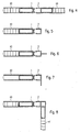
- Fig. 1 are edge portions of two profile elements 1, 2 shown in cross section.
- the profile elements 1, 2 have longitudinal edges 3, 3 ', which face each other. At least in the region of the longitudinal edges 3, 3 ', but in general over the entire surface of the profile elements 1, 2, upper cover surfaces 4, 4' and lower cover surfaces 5, 5 'are provided. Edges 6, 6 'and 7, 7' of the cover surfaces 4, 4 '; 5, 5 'are also arranged facing each other.
- a profile element 1 grooves 12, 12 ' are provided which are formed on one side of the vertical cover surface edges 7, 7' and which on its other, the second profile element facing side inclined surfaces 11, 11 'have. Corresponding to these V-shaped grooves are at the other
- Profile element 2 lugs 13, 13 ' is formed, which at its outer, the first profile element 1 side facing the cover surface edges 6, 6' and which on their opposite sides of the inclined surfaces 11, 11 'correspondingly shaped inclined surfaces 21, 21' have. In this way, a clamping element 10 and the second profile element 2, a clamping element 20 is formed on the first profile element 1.
- the lugs 13, 13 ' are hooked or snapped into the grooves 12, 12'.
- the top surfaces 4 ', 5' are formed so elastic that a bending and snapping back into the original shape is possible. This is achieved relatively easily by a corresponding shaping or dimensioning of the distance between the clamping elements 20 and a first support 8, which connects the upper cover surface 4 'with the lower cover surface 5'.
- the first profile element 1 has just such supports 9, so that a symmetrical structure is created.
- Friction-stir welding provides material bonding to a certain depth, with the result in Fig. 3 is shown. It can be seen that a weld between the upper deck surfaces 4, 4 'and the lower deck surfaces 5, 5' is made, the clamping elements for the most part "disappear" because the lugs 13, 13 'with the grooves 12, 12th 'surrounding material of the support members 30 are welded. The clamping elements are thus integrated cohesively in the final structure of the connecting element and serve as a material that increases strength.
- the profile elements 1, 2 are in the region in which they are welded together and thereby pressed against each other during welding, according to the embodiments of the Fig. 1-3 designed.
- the profile elements 1, 2 are at their, the junctions facing away from the sides formed such that they can be connected to components 40, 41, for example by gluing.
- These components 40, 41 are in the in the 4 - 6 and 8 arrangements shown plates or panels in which honeycomb interconnected cover plates made of a plastic are interconnected. Such panels are known per se.
- one of the profile elements namely, the profile element 2 is designed as a border element, so that a component 40, which is provided peripherally with the first profile element 1, can be closed by the profile element 2.
- Fig. 6 serves the edge-side profile element 2 not only to the completion of the other component, it also serves at the same time to its attachment, for example, on a frame and has corresponding holes on.
- Fig. 7 is different from the after Fig. 6 in that the element is angled for attachment to frames (or the like). It can be seen that in a simple way very large components can be produced, which can be provided at the edge with any type of fasteners to surrounding components, a frame or the like.
- the second profiled element 2 is configured in such a way that the second component 41 can be fastened thereto at a (90 °) angle to the first component 40.
- Such arrangements were previously produced only with the utmost effort and in particular with very expensive clamping tools.
- Fig. 9 embodiment of the invention shown differs from the Fig. 1 in that a completely symmetrical structure is met.
- support elements 30, 30 ' are provided on both profile elements 1, 2 or on their edges, which are provided with upper grooves 12 and lower grooves 12', which have the above-described inclined surfaces 11, 11 '.
- coupling elements 14, 14 ' are provided, which are also provided with grooves with inclined surfaces such that the coupling elements 14, 14' in the grooves 12, 12 'can be used while the said inclined surfaces each other to meet.
- the two profile elements 1, 2 are pressed together with their edges by this embodiment of the invention.
- the embodiment according to Fig. 11 is different from the after Fig. 5 in that the clamping element 20 is integrally connected to the support element 30 'of the second profile element 2.
- the V-shaped slot thus sits only in the support element 30 of the first profile element. The effect is otherwise the same as in the embodiment of FIG Fig. 10 ,
- a significant advantage of the invention is that components can be connected to one another in a simple manner. This is achieved, inter alia, that the seams, which are to be joined together by friction stir welding, are perpendicular to each other, so that no torques occur during friction stir welding, which would have to be intercepted by elaborate clamping devices. It should be remembered that the forces involved in friction-stir welding are quite significant. In a tool of 10 mm diameter, a force of about 6000 N is spent, so that unbalanced arrangements would lead to a very significant torque, which on the one hand bends the components, on the other hand would have to be absorbed by said devices.
Landscapes
- Engineering & Computer Science (AREA)
- Mechanical Engineering (AREA)
- Architecture (AREA)
- Civil Engineering (AREA)
- Structural Engineering (AREA)
- Chemical & Material Sciences (AREA)
- Combustion & Propulsion (AREA)
- Transportation (AREA)
- Life Sciences & Earth Sciences (AREA)
- Wood Science & Technology (AREA)
- Pressure Welding/Diffusion-Bonding (AREA)
- Connection Of Plates (AREA)
Claims (9)
- Elément d'assemblage pour l'assemblage de deux composants, en particulier de composants plats pour former des panneaux, comprenant au moins deux éléments profilés (1, 2) pouvant être soudés l'un à l'autre,
chaque élément profilé (1, 2) étant fabriqué sous la forme d'un profilé creux filé et présentant au moins dans la région de bords longitudinaux (3, 3') une surface de recouvrement supérieure (4, 4') et une surface de recouvrement inférieure (5, 5'), et
lors du soudage, en particulier un soudage par friction (FSW), une force de pression appliquée par au moins un outil de soudage (50, 51) agissant essentiellement perpendiculairement aux surfaces de recouvrement (4, 4' ; 5, 5'),
les éléments profilés (1, 2) comprenant des éléments de serrage (10, 20), dont au moins certaines parties sont réalisées d'une seule pièce avec les éléments profilés (1, 2), par le biais desquelles les éléments profilés (1, 2) peuvent être assemblés l'un à l'autre, les éléments de serrage (10, 20) étant réalisés de telle sorte que la force de pression (Fs' - Fs) soit déviée par les éléments de serrage (10, 20) au moins en partie dans une force horizontale (Fh' - Fh) qui presse l'un contre l'autre ou déplace l'un vers l'autre les éléments profilés (1, 2), les éléments de serrage (10, 20) comprenant des surfaces (11, 11' ; 21, 21') s'étendant obliquement par rapport à la force de pression, lesquelles surfaces sont réalisées et disposées de telle sorte que lors de l'application de la force de pression (Fs), les surfaces obliques (11, 21 ; 11', 21') puissent être déplacées l'une vers l'autre pour produire la force horizontale (Fh), les bords longitudinaux (6, 7) de la surface de recouvrement supérieure (4, 4') étant supportés contre les bords longitudinaux (6', 7') de la surface de recouvrement inférieure (5, 5') par un élément de support unique (30), et/ou se tenant verticalement les uns au-dessus des autres par rapport aux surfaces de recouvrement (4, 4' ; 5, 5'),
les éléments de serrage (10, 20) étant disposés essentiellement symétriquement par rapport à un plan qui est disposé au centre entre la surface de recouvrement supérieure et la surface de recouvrement inférieure (4, 5) et parallèlement à celles-ci, de telle sorte que les surfaces de recouvrement supérieures (4, 4') et les surfaces de recouvrement inférieures (5, 5') de deux éléments profilés (1, 2) puissent être soudées les unes aux autres avec des outils de soudage de même type (50, 51). - Elément d'assemblage selon la revendication 1,
caractérisé en ce que
les éléments de support (30, 30') sont prévus entre la surface de recouvrement supérieure et la surface de recouvrement inférieure (4, 5) en supportant celles-ci l'une contre l'autre, pour absorber la force de pression (Fs). - Elément d'assemblage selon l'une quelconque des revendications précédentes, en particulier selon la revendication 2,
caractérisé en ce que
les éléments de serrage (10, 20) comprennent au moins des parties des éléments de support (30, 30'). - Elément d'assemblage selon l'une quelconque des revendications précédentes,
caractérisé en ce que
les éléments de serrage (10, 20) sont réalisés de telle sorte que les surfaces de recouvrement (4, 5) des éléments profilés (1, 2) soient pressées l'une contre l'autre avec leurs bords respectifs (6, 7) lors du soudage. - Elément d'assemblage selon l'une quelconque des revendications précédentes,
caractérisé en ce que
les éléments de serrage (10, 20) sont réalisés et disposés de telle sorte qu'ils soient soudés aux surfaces de recouvrement (4, 5) lors du soudage. - Elément d'assemblage selon l'une quelconque des revendications précédentes,
caractérisé en ce que
les éléments de serrage (10, 20) sont réalisés de manière élastique à ressort de telle sorte que les éléments profilés (1, 2) puissent être amenés en engagement d'encliquetage l'un avec l'autre. - Elément d'assemblage selon l'une quelconque des revendications précédentes,
caractérisé en ce que
les éléments de serrage (10, 20) comprennent un agencement de levier (25 - 27), qui est disposé et réalisé de telle sorte que la force de pression (Fs) puisse être déviée au moins en partie dans la force horizontale (Fh). - Elément d'assemblage selon l'une quelconque des revendications précédentes,
caractérisé en ce que
les éléments de serrage (10, 20) sont réalisés avec une symétrie spéculaire au niveau des bords longitudinaux (3, 3') des éléments profilés (1, 2). - Elément d'assemblage selon l'une quelconque des revendications précédentes,
caractérisé en ce que
les éléments profilés (1, 2) sont fabriqués en aluminium.
Applications Claiming Priority (2)
| Application Number | Priority Date | Filing Date | Title |
|---|---|---|---|
| DE102005048001A DE102005048001B4 (de) | 2005-10-06 | 2005-10-06 | Verbindungselement |
| PCT/EP2006/009027 WO2007039073A1 (fr) | 2005-10-06 | 2006-09-15 | Element d'assemblage |
Publications (2)
| Publication Number | Publication Date |
|---|---|
| EP1931494A1 EP1931494A1 (fr) | 2008-06-18 |
| EP1931494B1 true EP1931494B1 (fr) | 2012-03-28 |
Family
ID=37434174
Family Applications (1)
| Application Number | Title | Priority Date | Filing Date |
|---|---|---|---|
| EP06792108A Not-in-force EP1931494B1 (fr) | 2005-10-06 | 2006-09-15 | Element d'assemblage |
Country Status (5)
| Country | Link |
|---|---|
| EP (1) | EP1931494B1 (fr) |
| AT (1) | ATE551146T1 (fr) |
| DE (1) | DE102005048001B4 (fr) |
| ES (1) | ES2381570T3 (fr) |
| WO (1) | WO2007039073A1 (fr) |
Cited By (1)
| Publication number | Priority date | Publication date | Assignee | Title |
|---|---|---|---|---|
| US11702146B2 (en) * | 2019-05-21 | 2023-07-18 | Volvo Bus Corporation | Vehicle body element connecting joint |
Families Citing this family (10)
| Publication number | Priority date | Publication date | Assignee | Title |
|---|---|---|---|---|
| DE102007010262A1 (de) * | 2007-03-02 | 2008-09-04 | Siemens Ag | Leichtbaustruktur |
| DE102007018459B4 (de) * | 2007-04-19 | 2011-11-24 | Audi Ag | Karosseriebauteil für einen Kraftwagen |
| PL2123542T3 (pl) * | 2008-05-09 | 2016-11-30 | Element podłogowy do pojazdu, na przykład samochodu ciężarowego, naczepy lub przyczepy | |
| DE102009050775B4 (de) * | 2009-10-27 | 2012-06-06 | Audi Ag | Verbundprofil bestehend aus wenigstens einem ersten und zweiten Metallprofilteil |
| FI126176B (sv) | 2011-10-17 | 2016-07-29 | Uponor Infra Oy | Förfarande för framställning av skivformiga strukturer |
| DE102013100215A1 (de) * | 2013-01-10 | 2014-07-10 | F. Hesterberg & Söhne Gmbh & Co. Kg | verschließbare Türanordnung für einen Nutzfahrzeugaufbau |
| CN110678379B (zh) * | 2017-06-14 | 2022-06-14 | 沃尔沃卡车集团 | 车身模块连接接头 |
| DE102018126814A1 (de) * | 2018-10-26 | 2020-04-30 | Bombardier Transportation Gmbh | Hüllstruktur für einen Wagenkasten und Verfahren zur Herstellung einer Hüllstruktur |
| CA3087758A1 (fr) | 2019-07-25 | 2021-01-25 | National Research Council Of Canada | Extrusions encliquetables pour former des panneaux |
| GB2602014B (en) * | 2020-12-15 | 2024-03-27 | Bombardier Transp Gmbh | Manufacturing a rail vehicle carbody out of slidable profiles |
Family Cites Families (11)
| Publication number | Priority date | Publication date | Assignee | Title |
|---|---|---|---|---|
| GB2228277B (en) * | 1989-01-31 | 1993-03-10 | Harris B J | Decking members |
| CN100441935C (zh) * | 1996-03-19 | 2008-12-10 | 株式会社日立制作所 | 镶板结构体 |
| JP3070735B2 (ja) * | 1997-07-23 | 2000-07-31 | 株式会社日立製作所 | 摩擦攪拌接合方法 |
| JPH11267859A (ja) * | 1998-03-17 | 1999-10-05 | Sumitomo Light Metal Ind Ltd | 接合用加工材とその接合方法及び接合された加工パネル |
| JP3506173B2 (ja) * | 1998-06-05 | 2004-03-15 | 日本軽金属株式会社 | 水密構造 |
| JP3481501B2 (ja) * | 1999-05-28 | 2003-12-22 | 株式会社日立製作所 | 構造体およびその製作方法 |
| JP4414035B2 (ja) * | 1999-12-08 | 2010-02-10 | 昭和電工株式会社 | 摩擦撹拌接合法 |
| DE10224198C1 (de) * | 2002-05-31 | 2003-08-14 | Erbsloeh Ag | Leichtbauelement und Herstellungsverfahren |
| JP2004230412A (ja) * | 2003-01-29 | 2004-08-19 | Kawasaki Heavy Ind Ltd | 中空押出し形材の接合構造 |
| US6933057B2 (en) * | 2003-07-17 | 2005-08-23 | The Boeing Company | Friction stir welded assembly and method of forming a friction stir welded assembly |
| EP1621282A1 (fr) * | 2004-07-09 | 2006-02-01 | Horst Witte Entwicklungs- und Vertriebs-KG | Panneau sandwich notamment pour la réalisation de dispositifs de fixation de pièces et procédé de fabrication d' un tel panneau sandwich |
-
2005
- 2005-10-06 DE DE102005048001A patent/DE102005048001B4/de not_active Expired - Fee Related
-
2006
- 2006-09-15 AT AT06792108T patent/ATE551146T1/de active
- 2006-09-15 ES ES06792108T patent/ES2381570T3/es active Active
- 2006-09-15 WO PCT/EP2006/009027 patent/WO2007039073A1/fr active Application Filing
- 2006-09-15 EP EP06792108A patent/EP1931494B1/fr not_active Not-in-force
Cited By (1)
| Publication number | Priority date | Publication date | Assignee | Title |
|---|---|---|---|---|
| US11702146B2 (en) * | 2019-05-21 | 2023-07-18 | Volvo Bus Corporation | Vehicle body element connecting joint |
Also Published As
| Publication number | Publication date |
|---|---|
| WO2007039073A1 (fr) | 2007-04-12 |
| EP1931494A1 (fr) | 2008-06-18 |
| ES2381570T3 (es) | 2012-05-29 |
| ATE551146T1 (de) | 2012-04-15 |
| DE102005048001A1 (de) | 2007-04-19 |
| DE102005048001B4 (de) | 2007-06-14 |
Similar Documents
| Publication | Publication Date | Title |
|---|---|---|
| EP1931494B1 (fr) | Element d'assemblage | |
| EP2084033B1 (fr) | Élément structurel pour siège de véhicule | |
| DE69736017T2 (de) | Plattenstruktur und Reibschweissverfahren | |
| DE60031036T2 (de) | Struktureller Körper und Verfahren zu seiner Herstellung | |
| DE60027687T2 (de) | Drehendes Reibungschweissverfahren und struktureller Körper. | |
| DE60031009T2 (de) | Bauteil zur Anwendung bei einem drehenden Reibungschweißverfahren | |
| EP2197623B1 (fr) | Procédé de fabrication de machines | |
| AT515130B1 (de) | Biegepresse | |
| DE102007042169B4 (de) | Strukturteil für einen Fahrzeugsitz sowie Verfahren zu dessen Herstellung | |
| EP2159366A2 (fr) | Procédé et dispositif de fabrication d'un cadre intercalaire carré pour vitres d'isolation | |
| DE60111777T2 (de) | Anordnung zur verbindung von rahmenlängsträgern | |
| EP2318607B1 (fr) | Structure de surface | |
| DE19748613C1 (de) | Verbindungselement für Rahmenprofile | |
| DE102007003983B4 (de) | Hohlträger für ein Kraftfahrzeug | |
| DE3729620A1 (de) | Fahrzeugaufbau, insbesondere kofferaufbau | |
| DE202012104117U1 (de) | Stoßfängerquerträgerbaugruppe | |
| DE102018127251B3 (de) | Verbindungsprofil und verfahren zum dauerhaften fügen zweier platten sowie system mit einem verbindungsprofil | |
| EP1103348B1 (fr) | Dispositif de soudage de cadres | |
| EP1925392B1 (fr) | Dispositif et procédé destinés à la réparation d'un revêtement | |
| DE102018132219B4 (de) | Batteriegehäuse mit einer aus Rahmenstrukturteilen zusammengesetzten Rahmenstruktur | |
| DE10009106C1 (de) | Flächenelement und Verfahren zum Herstellen eines Flächenelements | |
| EP1658941A1 (fr) | Appareil de plaçage de chants portable | |
| DE10336589B3 (de) | Verfahren zur Reparatur von aus Profilteilen bestehenden Tragstrukturen, insbesondere Rahmenkonstruktionen von Kraftfahrzeug-Karosserien | |
| EP1930490A2 (fr) | Traverse pour lame de métier à tisser | |
| AT522193B1 (de) | Element für eine Schallschutzwand |
Legal Events
| Date | Code | Title | Description |
|---|---|---|---|
| PUAI | Public reference made under article 153(3) epc to a published international application that has entered the european phase |
Free format text: ORIGINAL CODE: 0009012 |
|
| 17P | Request for examination filed |
Effective date: 20080327 |
|
| AK | Designated contracting states |
Kind code of ref document: A1 Designated state(s): AT BE BG CH CY CZ DE DK EE ES FI FR GB GR HU IE IS IT LI LT LU LV MC NL PL PT RO SE SI SK TR |
|
| 17Q | First examination report despatched |
Effective date: 20100108 |
|
| GRAP | Despatch of communication of intention to grant a patent |
Free format text: ORIGINAL CODE: EPIDOSNIGR1 |
|
| DAX | Request for extension of the european patent (deleted) | ||
| GRAS | Grant fee paid |
Free format text: ORIGINAL CODE: EPIDOSNIGR3 |
|
| GRAA | (expected) grant |
Free format text: ORIGINAL CODE: 0009210 |
|
| AK | Designated contracting states |
Kind code of ref document: B1 Designated state(s): AT BE BG CH CY CZ DE DK EE ES FI FR GB GR HU IE IS IT LI LT LU LV MC NL PL PT RO SE SI SK TR |
|
| REG | Reference to a national code |
Ref country code: GB Ref legal event code: FG4D Free format text: NOT ENGLISH |
|
| REG | Reference to a national code |
Ref country code: CH Ref legal event code: NV Representative=s name: FIAMMENGHI-FIAMMENGHI Ref country code: CH Ref legal event code: EP |
|
| REG | Reference to a national code |
Ref country code: AT Ref legal event code: REF Ref document number: 551146 Country of ref document: AT Kind code of ref document: T Effective date: 20120415 |
|
| REG | Reference to a national code |
Ref country code: IE Ref legal event code: FG4D Free format text: LANGUAGE OF EP DOCUMENT: GERMAN |
|
| REG | Reference to a national code |
Ref country code: DE Ref legal event code: R096 Ref document number: 502006011217 Country of ref document: DE Effective date: 20120524 |
|
| REG | Reference to a national code |
Ref country code: ES Ref legal event code: FG2A Ref document number: 2381570 Country of ref document: ES Kind code of ref document: T3 Effective date: 20120529 |
|
| REG | Reference to a national code |
Ref country code: NL Ref legal event code: T3 |
|
| REG | Reference to a national code |
Ref country code: SE Ref legal event code: TRGR |
|
| PG25 | Lapsed in a contracting state [announced via postgrant information from national office to epo] |
Ref country code: LT Free format text: LAPSE BECAUSE OF FAILURE TO SUBMIT A TRANSLATION OF THE DESCRIPTION OR TO PAY THE FEE WITHIN THE PRESCRIBED TIME-LIMIT Effective date: 20120328 |
|
| LTIE | Lt: invalidation of european patent or patent extension |
Effective date: 20120328 |
|
| PG25 | Lapsed in a contracting state [announced via postgrant information from national office to epo] |
Ref country code: GR Free format text: LAPSE BECAUSE OF FAILURE TO SUBMIT A TRANSLATION OF THE DESCRIPTION OR TO PAY THE FEE WITHIN THE PRESCRIBED TIME-LIMIT Effective date: 20120629 Ref country code: FI Free format text: LAPSE BECAUSE OF FAILURE TO SUBMIT A TRANSLATION OF THE DESCRIPTION OR TO PAY THE FEE WITHIN THE PRESCRIBED TIME-LIMIT Effective date: 20120328 Ref country code: LV Free format text: LAPSE BECAUSE OF FAILURE TO SUBMIT A TRANSLATION OF THE DESCRIPTION OR TO PAY THE FEE WITHIN THE PRESCRIBED TIME-LIMIT Effective date: 20120328 |
|
| PG25 | Lapsed in a contracting state [announced via postgrant information from national office to epo] |
Ref country code: CY Free format text: LAPSE BECAUSE OF FAILURE TO SUBMIT A TRANSLATION OF THE DESCRIPTION OR TO PAY THE FEE WITHIN THE PRESCRIBED TIME-LIMIT Effective date: 20120328 |
|
| PG25 | Lapsed in a contracting state [announced via postgrant information from national office to epo] |
Ref country code: IS Free format text: LAPSE BECAUSE OF FAILURE TO SUBMIT A TRANSLATION OF THE DESCRIPTION OR TO PAY THE FEE WITHIN THE PRESCRIBED TIME-LIMIT Effective date: 20120728 Ref country code: RO Free format text: LAPSE BECAUSE OF FAILURE TO SUBMIT A TRANSLATION OF THE DESCRIPTION OR TO PAY THE FEE WITHIN THE PRESCRIBED TIME-LIMIT Effective date: 20120328 Ref country code: SI Free format text: LAPSE BECAUSE OF FAILURE TO SUBMIT A TRANSLATION OF THE DESCRIPTION OR TO PAY THE FEE WITHIN THE PRESCRIBED TIME-LIMIT Effective date: 20120328 Ref country code: PL Free format text: LAPSE BECAUSE OF FAILURE TO SUBMIT A TRANSLATION OF THE DESCRIPTION OR TO PAY THE FEE WITHIN THE PRESCRIBED TIME-LIMIT Effective date: 20120328 Ref country code: CZ Free format text: LAPSE BECAUSE OF FAILURE TO SUBMIT A TRANSLATION OF THE DESCRIPTION OR TO PAY THE FEE WITHIN THE PRESCRIBED TIME-LIMIT Effective date: 20120328 Ref country code: EE Free format text: LAPSE BECAUSE OF FAILURE TO SUBMIT A TRANSLATION OF THE DESCRIPTION OR TO PAY THE FEE WITHIN THE PRESCRIBED TIME-LIMIT Effective date: 20120328 |
|
| PG25 | Lapsed in a contracting state [announced via postgrant information from national office to epo] |
Ref country code: SK Free format text: LAPSE BECAUSE OF FAILURE TO SUBMIT A TRANSLATION OF THE DESCRIPTION OR TO PAY THE FEE WITHIN THE PRESCRIBED TIME-LIMIT Effective date: 20120328 Ref country code: PT Free format text: LAPSE BECAUSE OF FAILURE TO SUBMIT A TRANSLATION OF THE DESCRIPTION OR TO PAY THE FEE WITHIN THE PRESCRIBED TIME-LIMIT Effective date: 20120730 |
|
| PG25 | Lapsed in a contracting state [announced via postgrant information from national office to epo] |
Ref country code: DK Free format text: LAPSE BECAUSE OF FAILURE TO SUBMIT A TRANSLATION OF THE DESCRIPTION OR TO PAY THE FEE WITHIN THE PRESCRIBED TIME-LIMIT Effective date: 20120328 |
|
| PLBE | No opposition filed within time limit |
Free format text: ORIGINAL CODE: 0009261 |
|
| STAA | Information on the status of an ep patent application or granted ep patent |
Free format text: STATUS: NO OPPOSITION FILED WITHIN TIME LIMIT |
|
| 26N | No opposition filed |
Effective date: 20130103 |
|
| REG | Reference to a national code |
Ref country code: DE Ref legal event code: R097 Ref document number: 502006011217 Country of ref document: DE Effective date: 20130103 |
|
| PG25 | Lapsed in a contracting state [announced via postgrant information from national office to epo] |
Ref country code: MC Free format text: LAPSE BECAUSE OF NON-PAYMENT OF DUE FEES Effective date: 20120930 |
|
| GBPC | Gb: european patent ceased through non-payment of renewal fee |
Effective date: 20120915 |
|
| REG | Reference to a national code |
Ref country code: IE Ref legal event code: MM4A |
|
| PG25 | Lapsed in a contracting state [announced via postgrant information from national office to epo] |
Ref country code: GB Free format text: LAPSE BECAUSE OF NON-PAYMENT OF DUE FEES Effective date: 20120915 Ref country code: BG Free format text: LAPSE BECAUSE OF FAILURE TO SUBMIT A TRANSLATION OF THE DESCRIPTION OR TO PAY THE FEE WITHIN THE PRESCRIBED TIME-LIMIT Effective date: 20120628 Ref country code: IE Free format text: LAPSE BECAUSE OF NON-PAYMENT OF DUE FEES Effective date: 20120915 |
|
| PG25 | Lapsed in a contracting state [announced via postgrant information from national office to epo] |
Ref country code: LU Free format text: LAPSE BECAUSE OF NON-PAYMENT OF DUE FEES Effective date: 20120915 |
|
| PG25 | Lapsed in a contracting state [announced via postgrant information from national office to epo] |
Ref country code: HU Free format text: LAPSE BECAUSE OF FAILURE TO SUBMIT A TRANSLATION OF THE DESCRIPTION OR TO PAY THE FEE WITHIN THE PRESCRIBED TIME-LIMIT Effective date: 20060915 |
|
| PGFP | Annual fee paid to national office [announced via postgrant information from national office to epo] |
Ref country code: TR Payment date: 20140822 Year of fee payment: 9 |
|
| REG | Reference to a national code |
Ref country code: FR Ref legal event code: PLFP Year of fee payment: 10 |
|
| PGFP | Annual fee paid to national office [announced via postgrant information from national office to epo] |
Ref country code: CH Payment date: 20150925 Year of fee payment: 10 |
|
| PGFP | Annual fee paid to national office [announced via postgrant information from national office to epo] |
Ref country code: AT Payment date: 20150925 Year of fee payment: 10 Ref country code: FR Payment date: 20150630 Year of fee payment: 10 Ref country code: SE Payment date: 20150928 Year of fee payment: 10 |
|
| PGFP | Annual fee paid to national office [announced via postgrant information from national office to epo] |
Ref country code: IT Payment date: 20150925 Year of fee payment: 10 Ref country code: DE Payment date: 20151127 Year of fee payment: 10 |
|
| PGFP | Annual fee paid to national office [announced via postgrant information from national office to epo] |
Ref country code: BE Payment date: 20150930 Year of fee payment: 10 Ref country code: NL Payment date: 20150928 Year of fee payment: 10 Ref country code: ES Payment date: 20151027 Year of fee payment: 10 |
|
| PG25 | Lapsed in a contracting state [announced via postgrant information from national office to epo] |
Ref country code: BE Free format text: LAPSE BECAUSE OF NON-PAYMENT OF DUE FEES Effective date: 20160930 |
|
| REG | Reference to a national code |
Ref country code: DE Ref legal event code: R119 Ref document number: 502006011217 Country of ref document: DE |
|
| PG25 | Lapsed in a contracting state [announced via postgrant information from national office to epo] |
Ref country code: SE Free format text: LAPSE BECAUSE OF NON-PAYMENT OF DUE FEES Effective date: 20160916 |
|
| REG | Reference to a national code |
Ref country code: CH Ref legal event code: PL |
|
| REG | Reference to a national code |
Ref country code: SE Ref legal event code: EUG |
|
| REG | Reference to a national code |
Ref country code: NL Ref legal event code: MM Effective date: 20161001 |
|
| REG | Reference to a national code |
Ref country code: AT Ref legal event code: MM01 Ref document number: 551146 Country of ref document: AT Kind code of ref document: T Effective date: 20160915 |
|
| PG25 | Lapsed in a contracting state [announced via postgrant information from national office to epo] |
Ref country code: NL Free format text: LAPSE BECAUSE OF NON-PAYMENT OF DUE FEES Effective date: 20161001 |
|
| REG | Reference to a national code |
Ref country code: FR Ref legal event code: ST Effective date: 20170531 |
|
| PG25 | Lapsed in a contracting state [announced via postgrant information from national office to epo] |
Ref country code: LI Free format text: LAPSE BECAUSE OF NON-PAYMENT OF DUE FEES Effective date: 20160930 Ref country code: FR Free format text: LAPSE BECAUSE OF NON-PAYMENT OF DUE FEES Effective date: 20160930 Ref country code: DE Free format text: LAPSE BECAUSE OF NON-PAYMENT OF DUE FEES Effective date: 20170401 Ref country code: CH Free format text: LAPSE BECAUSE OF NON-PAYMENT OF DUE FEES Effective date: 20160930 |
|
| PG25 | Lapsed in a contracting state [announced via postgrant information from national office to epo] |
Ref country code: AT Free format text: LAPSE BECAUSE OF NON-PAYMENT OF DUE FEES Effective date: 20160915 Ref country code: IT Free format text: LAPSE BECAUSE OF NON-PAYMENT OF DUE FEES Effective date: 20160915 |
|
| REG | Reference to a national code |
Ref country code: BE Ref legal event code: MM Effective date: 20160930 |
|
| PG25 | Lapsed in a contracting state [announced via postgrant information from national office to epo] |
Ref country code: ES Free format text: LAPSE BECAUSE OF NON-PAYMENT OF DUE FEES Effective date: 20160916 |
|
| REG | Reference to a national code |
Ref country code: ES Ref legal event code: FD2A Effective date: 20181129 |
|
| PG25 | Lapsed in a contracting state [announced via postgrant information from national office to epo] |
Ref country code: TR Free format text: LAPSE BECAUSE OF NON-PAYMENT OF DUE FEES Effective date: 20160915 |