EP1931494B1 - Joining element - Google Patents
Joining element Download PDFInfo
- Publication number
- EP1931494B1 EP1931494B1 EP06792108A EP06792108A EP1931494B1 EP 1931494 B1 EP1931494 B1 EP 1931494B1 EP 06792108 A EP06792108 A EP 06792108A EP 06792108 A EP06792108 A EP 06792108A EP 1931494 B1 EP1931494 B1 EP 1931494B1
- Authority
- EP
- European Patent Office
- Prior art keywords
- elements
- clamping elements
- another
- profiled
- clamping
- Prior art date
- Legal status (The legal status is an assumption and is not a legal conclusion. Google has not performed a legal analysis and makes no representation as to the accuracy of the status listed.)
- Not-in-force
Links
- 238000003466 welding Methods 0.000 claims abstract description 43
- 238000003825 pressing Methods 0.000 claims abstract description 15
- 238000003756 stirring Methods 0.000 claims abstract description 14
- XAGFODPZIPBFFR-UHFFFAOYSA-N aluminium Chemical compound [Al] XAGFODPZIPBFFR-UHFFFAOYSA-N 0.000 claims description 3
- 229910052782 aluminium Inorganic materials 0.000 claims description 3
- 239000004411 aluminium Substances 0.000 claims 1
- 239000000463 material Substances 0.000 description 7
- 238000004519 manufacturing process Methods 0.000 description 5
- 238000000034 method Methods 0.000 description 5
- 230000008878 coupling Effects 0.000 description 3
- 238000010168 coupling process Methods 0.000 description 3
- 238000005859 coupling reaction Methods 0.000 description 3
- 238000004026 adhesive bonding Methods 0.000 description 2
- 238000005452 bending Methods 0.000 description 2
- 238000010276 construction Methods 0.000 description 2
- 239000002131 composite material Substances 0.000 description 1
- 230000001419 dependent effect Effects 0.000 description 1
- 230000000694 effects Effects 0.000 description 1
- 238000007493 shaping process Methods 0.000 description 1
Images


Classifications
-
- E—FIXED CONSTRUCTIONS
- E04—BUILDING
- E04C—STRUCTURAL ELEMENTS; BUILDING MATERIALS
- E04C2/00—Building elements of relatively thin form for the construction of parts of buildings, e.g. sheet materials, slabs, or panels
- E04C2/30—Building elements of relatively thin form for the construction of parts of buildings, e.g. sheet materials, slabs, or panels characterised by the shape or structure
- E04C2/34—Building elements of relatively thin form for the construction of parts of buildings, e.g. sheet materials, slabs, or panels characterised by the shape or structure composed of two or more spaced sheet-like parts
-
- B—PERFORMING OPERATIONS; TRANSPORTING
- B23—MACHINE TOOLS; METAL-WORKING NOT OTHERWISE PROVIDED FOR
- B23K—SOLDERING OR UNSOLDERING; WELDING; CLADDING OR PLATING BY SOLDERING OR WELDING; CUTTING BY APPLYING HEAT LOCALLY, e.g. FLAME CUTTING; WORKING BY LASER BEAM
- B23K20/00—Non-electric welding by applying impact or other pressure, with or without the application of heat, e.g. cladding or plating
- B23K20/12—Non-electric welding by applying impact or other pressure, with or without the application of heat, e.g. cladding or plating the heat being generated by friction; Friction welding
- B23K20/122—Non-electric welding by applying impact or other pressure, with or without the application of heat, e.g. cladding or plating the heat being generated by friction; Friction welding using a non-consumable tool, e.g. friction stir welding
-
- B—PERFORMING OPERATIONS; TRANSPORTING
- B23—MACHINE TOOLS; METAL-WORKING NOT OTHERWISE PROVIDED FOR
- B23K—SOLDERING OR UNSOLDERING; WELDING; CLADDING OR PLATING BY SOLDERING OR WELDING; CUTTING BY APPLYING HEAT LOCALLY, e.g. FLAME CUTTING; WORKING BY LASER BEAM
- B23K33/00—Specially-profiled edge portions of workpieces for making soldering or welding connections; Filling the seams formed thereby
- B23K33/004—Filling of continuous seams
-
- B—PERFORMING OPERATIONS; TRANSPORTING
- B61—RAILWAYS
- B61D—BODY DETAILS OR KINDS OF RAILWAY VEHICLES
- B61D17/00—Construction details of vehicle bodies
- B61D17/04—Construction details of vehicle bodies with bodies of metal; with composite, e.g. metal and wood body structures
- B61D17/043—Construction details of vehicle bodies with bodies of metal; with composite, e.g. metal and wood body structures connections between superstructure sub-units
-
- B—PERFORMING OPERATIONS; TRANSPORTING
- B62—LAND VEHICLES FOR TRAVELLING OTHERWISE THAN ON RAILS
- B62D—MOTOR VEHICLES; TRAILERS
- B62D33/00—Superstructures for load-carrying vehicles
- B62D33/02—Platforms; Open load compartments
- B62D33/023—Sideboard or tailgate structures
-
- B—PERFORMING OPERATIONS; TRANSPORTING
- B62—LAND VEHICLES FOR TRAVELLING OTHERWISE THAN ON RAILS
- B62D—MOTOR VEHICLES; TRAILERS
- B62D33/00—Superstructures for load-carrying vehicles
- B62D33/04—Enclosed load compartments ; Frameworks for movable panels, tarpaulins or side curtains
- B62D33/046—Enclosed load compartments ; Frameworks for movable panels, tarpaulins or side curtains built up with flat self-supporting panels; Fixed connections between panels
-
- E—FIXED CONSTRUCTIONS
- E04—BUILDING
- E04C—STRUCTURAL ELEMENTS; BUILDING MATERIALS
- E04C2/00—Building elements of relatively thin form for the construction of parts of buildings, e.g. sheet materials, slabs, or panels
- E04C2/02—Building elements of relatively thin form for the construction of parts of buildings, e.g. sheet materials, slabs, or panels characterised by specified materials
- E04C2/08—Building elements of relatively thin form for the construction of parts of buildings, e.g. sheet materials, slabs, or panels characterised by specified materials of metal, e.g. sheet metal
-
- B—PERFORMING OPERATIONS; TRANSPORTING
- B23—MACHINE TOOLS; METAL-WORKING NOT OTHERWISE PROVIDED FOR
- B23K—SOLDERING OR UNSOLDERING; WELDING; CLADDING OR PLATING BY SOLDERING OR WELDING; CUTTING BY APPLYING HEAT LOCALLY, e.g. FLAME CUTTING; WORKING BY LASER BEAM
- B23K2101/00—Articles made by soldering, welding or cutting
- B23K2101/04—Tubular or hollow articles
- B23K2101/045—Hollow panels
-
- E—FIXED CONSTRUCTIONS
- E04—BUILDING
- E04B—GENERAL BUILDING CONSTRUCTIONS; WALLS, e.g. PARTITIONS; ROOFS; FLOORS; CEILINGS; INSULATION OR OTHER PROTECTION OF BUILDINGS
- E04B1/00—Constructions in general; Structures which are not restricted either to walls, e.g. partitions, or floors or ceilings or roofs
- E04B1/38—Connections for building structures in general
- E04B1/61—Connections for building structures in general of slab-shaped building elements with each other
- E04B1/6108—Connections for building structures in general of slab-shaped building elements with each other the frontal surfaces of the slabs connected together
- E04B1/6116—Connections for building structures in general of slab-shaped building elements with each other the frontal surfaces of the slabs connected together by locking means on lateral surfaces
-
- E—FIXED CONSTRUCTIONS
- E04—BUILDING
- E04B—GENERAL BUILDING CONSTRUCTIONS; WALLS, e.g. PARTITIONS; ROOFS; FLOORS; CEILINGS; INSULATION OR OTHER PROTECTION OF BUILDINGS
- E04B1/00—Constructions in general; Structures which are not restricted either to walls, e.g. partitions, or floors or ceilings or roofs
- E04B1/38—Connections for building structures in general
- E04B1/61—Connections for building structures in general of slab-shaped building elements with each other
- E04B1/6108—Connections for building structures in general of slab-shaped building elements with each other the frontal surfaces of the slabs connected together
- E04B1/612—Connections for building structures in general of slab-shaped building elements with each other the frontal surfaces of the slabs connected together by means between frontal surfaces
- E04B1/6125—Connections for building structures in general of slab-shaped building elements with each other the frontal surfaces of the slabs connected together by means between frontal surfaces with protrusions on the one frontal surface co-operating with recesses in the other frontal surface
- E04B1/6137—Connections for building structures in general of slab-shaped building elements with each other the frontal surfaces of the slabs connected together by means between frontal surfaces with protrusions on the one frontal surface co-operating with recesses in the other frontal surface the connection made by formlocking
-
- E—FIXED CONSTRUCTIONS
- E04—BUILDING
- E04B—GENERAL BUILDING CONSTRUCTIONS; WALLS, e.g. PARTITIONS; ROOFS; FLOORS; CEILINGS; INSULATION OR OTHER PROTECTION OF BUILDINGS
- E04B1/00—Constructions in general; Structures which are not restricted either to walls, e.g. partitions, or floors or ceilings or roofs
- E04B1/38—Connections for building structures in general
- E04B1/61—Connections for building structures in general of slab-shaped building elements with each other
- E04B1/6108—Connections for building structures in general of slab-shaped building elements with each other the frontal surfaces of the slabs connected together
- E04B1/612—Connections for building structures in general of slab-shaped building elements with each other the frontal surfaces of the slabs connected together by means between frontal surfaces
- E04B1/6145—Connections for building structures in general of slab-shaped building elements with each other the frontal surfaces of the slabs connected together by means between frontal surfaces with recesses in both frontal surfaces co-operating with an additional connecting element
Definitions
- the invention relates to a connecting element which consists of at least two profile elements which can be welded to one another, as can be seen for example from US Pat JP 11 267 859 is known.
- components in particular flat components, must be connected to each other over longer welds.
- laser welding is often used, but this method is expensive.
- Connecting elements ie surface elements, such as those from the GB 2 228 277 A are known, are widely used for building in particular of walls.
- a typical example of this in railroad construction are eg wagon boxes or components in aircraft.
- Large-area fasteners are generally made of several profile elements, which are welded together at their edges.
- connecting element which consists of two profile elements which are connected to each other on the underside of a hook-shaped connection tensile strength.
- a weld seam is pulled by means of friction-stir welding (FSW), which connects the profile elements to one another on the upper side.
- FSW friction-stir welding
- panels can be interconnected by friction stir welding.
- the panels are hooked to each other at the edge, wherein the entanglement is, however, designed such that on the one hand an increased material cost is necessary, on the other hand a complex clamping tool must be used to ensure correct welding safe.
- the invention is based on the object to show a connecting element by means of which components can be connected to each other with little effort, wherein the connecting elements should be easily formed.
- a connecting element for connecting two components in particular flat components for forming panels, comprising at least two profile elements which can be welded to one another, each of which Profile element is made as extruded hollow profile and at least in the region of longitudinal edges of an upper deck surface and a lower
- a pressing force applied by at least one welding tool acts essentially perpendicular to the cover surfaces
- the profile elements comprising clamping elements of which at least parts are formed integrally with the profile elements, via which the profile elements can be connected to each other, wherein the clamping elements are formed such that the pressing force is deflected via the clamping elements at least partially in a horizontal force, which presses the profile elements together or moves to each other
- the clamping elements to the pressing force comprise inclined surfaces which formed and arranged are that upon application of the pressing force (F s ), the inclined surfaces are displaceable on each other for generating the horizontal force (F h ), wherein the longitudinal edges of the upper deck surface against the longitudinal edges of the lower deck surface by a single Supporting element are supported against each other and / or perpendicular to each other with respect to the top surfaces, wherein the clamping elements are arranged substantially symmetrically to a plane which is arranged in the middle between the upper and the lower top surface and parallel to these that
- An essential point of the invention lies in the fact that the clamping elements, which replace the otherwise necessary external clamping device and press the components to be welded together, in particular profile elements against each other, are made as parts of the profile elements or of the component or panel. This eliminates the significant cost of an external clamping device and the production itself is considerably simplified. As a result, in turn, that the force applied by the welding tool or the welding tools is converted into the necessary clamping force, the profile elements can not press apart an external clamping device against the fixed preset pressure force with increased contact pressure (as occurs in friction stir welding) Rather, at the same time the contact pressure of the profile elements is reinforced against each other with increased contact pressure of the welding tools.
- the invention not only in the production of large-scale Connecting elements is used, but is also suitable for connecting substantially arbitrarily shaped components.
- the term "connecting element" is thus also generally understood as a "component".
- support elements are provided between the upper and the lower cover surface, which support these against each other and intercept the pressure force of the welding tools.
- the clamping elements comprise at least parts of the support elements.
- the clamping elements are preferably formed such that the top surfaces of the profile elements are pressed together with their respective edges during welding. So it can be done a butt welding.
- the clamping elements are preferably designed and arranged such that they are welded to the cover surfaces during welding. Thus they serve at the same time to reinforce the resulting connecting element.
- the clamping elements are preferably designed so resiliently resilient that the profile elements can be brought together in a snap engagement. It can therefore be coupled by a simple handle the profile elements together and then firmly welded together.
- the clamping elements can be designed very different to ensure the "clamping principle" described above.
- the clamping elements can also simultaneously represent the snap engagement connection.
- the clamping elements may comprise a lever arrangement, which is arranged and designed such that the pressing force is at least partially deflected into the horizontal force.
- lever arrangements can be formed simultaneously as stiffening elements, wherein the lever arrangements need not have any real joints, but can only work due to their geometric shape with bending areas.
- the profile elements are made of aluminum. In this type of production and relatively complicated shapes can be produced inexpensively.
- clamping elements are formed on the longitudinal edges of the profile elements mirror-symmetrical, it is possible to work with a single type of edge covering elements, which form the outer edges of the connecting element.
- the fasteners may themselves already represent profile elements in their entirety, which are welded together to form panels. But it is also possible to form the connecting elements in such a way that differently produced elements, e.g. Profile elements made of honeycomb material are joined together. In this case, the profile elements required for the connection, which are very easy to handle due to their small extent, are connected to the elements made of honeycomb material, e.g. connected by gluing. The thus equipped with the fasteners surface elements can then be easily interconnected by friction-stir welding.
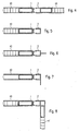
- Fig. 1 are edge portions of two profile elements 1, 2 shown in cross section.
- the profile elements 1, 2 have longitudinal edges 3, 3 ', which face each other. At least in the region of the longitudinal edges 3, 3 ', but in general over the entire surface of the profile elements 1, 2, upper cover surfaces 4, 4' and lower cover surfaces 5, 5 'are provided. Edges 6, 6 'and 7, 7' of the cover surfaces 4, 4 '; 5, 5 'are also arranged facing each other.
- a profile element 1 grooves 12, 12 ' are provided which are formed on one side of the vertical cover surface edges 7, 7' and which on its other, the second profile element facing side inclined surfaces 11, 11 'have. Corresponding to these V-shaped grooves are at the other
- Profile element 2 lugs 13, 13 ' is formed, which at its outer, the first profile element 1 side facing the cover surface edges 6, 6' and which on their opposite sides of the inclined surfaces 11, 11 'correspondingly shaped inclined surfaces 21, 21' have. In this way, a clamping element 10 and the second profile element 2, a clamping element 20 is formed on the first profile element 1.
- the lugs 13, 13 ' are hooked or snapped into the grooves 12, 12'.
- the top surfaces 4 ', 5' are formed so elastic that a bending and snapping back into the original shape is possible. This is achieved relatively easily by a corresponding shaping or dimensioning of the distance between the clamping elements 20 and a first support 8, which connects the upper cover surface 4 'with the lower cover surface 5'.
- the first profile element 1 has just such supports 9, so that a symmetrical structure is created.
- Friction-stir welding provides material bonding to a certain depth, with the result in Fig. 3 is shown. It can be seen that a weld between the upper deck surfaces 4, 4 'and the lower deck surfaces 5, 5' is made, the clamping elements for the most part "disappear" because the lugs 13, 13 'with the grooves 12, 12th 'surrounding material of the support members 30 are welded. The clamping elements are thus integrated cohesively in the final structure of the connecting element and serve as a material that increases strength.
- the profile elements 1, 2 are in the region in which they are welded together and thereby pressed against each other during welding, according to the embodiments of the Fig. 1-3 designed.
- the profile elements 1, 2 are at their, the junctions facing away from the sides formed such that they can be connected to components 40, 41, for example by gluing.
- These components 40, 41 are in the in the 4 - 6 and 8 arrangements shown plates or panels in which honeycomb interconnected cover plates made of a plastic are interconnected. Such panels are known per se.
- one of the profile elements namely, the profile element 2 is designed as a border element, so that a component 40, which is provided peripherally with the first profile element 1, can be closed by the profile element 2.
- Fig. 6 serves the edge-side profile element 2 not only to the completion of the other component, it also serves at the same time to its attachment, for example, on a frame and has corresponding holes on.
- Fig. 7 is different from the after Fig. 6 in that the element is angled for attachment to frames (or the like). It can be seen that in a simple way very large components can be produced, which can be provided at the edge with any type of fasteners to surrounding components, a frame or the like.
- the second profiled element 2 is configured in such a way that the second component 41 can be fastened thereto at a (90 °) angle to the first component 40.
- Such arrangements were previously produced only with the utmost effort and in particular with very expensive clamping tools.
- Fig. 9 embodiment of the invention shown differs from the Fig. 1 in that a completely symmetrical structure is met.
- support elements 30, 30 ' are provided on both profile elements 1, 2 or on their edges, which are provided with upper grooves 12 and lower grooves 12', which have the above-described inclined surfaces 11, 11 '.
- coupling elements 14, 14 ' are provided, which are also provided with grooves with inclined surfaces such that the coupling elements 14, 14' in the grooves 12, 12 'can be used while the said inclined surfaces each other to meet.
- the two profile elements 1, 2 are pressed together with their edges by this embodiment of the invention.
- the embodiment according to Fig. 11 is different from the after Fig. 5 in that the clamping element 20 is integrally connected to the support element 30 'of the second profile element 2.
- the V-shaped slot thus sits only in the support element 30 of the first profile element. The effect is otherwise the same as in the embodiment of FIG Fig. 10 ,
- a significant advantage of the invention is that components can be connected to one another in a simple manner. This is achieved, inter alia, that the seams, which are to be joined together by friction stir welding, are perpendicular to each other, so that no torques occur during friction stir welding, which would have to be intercepted by elaborate clamping devices. It should be remembered that the forces involved in friction-stir welding are quite significant. In a tool of 10 mm diameter, a force of about 6000 N is spent, so that unbalanced arrangements would lead to a very significant torque, which on the one hand bends the components, on the other hand would have to be absorbed by said devices.
Landscapes
- Engineering & Computer Science (AREA)
- Mechanical Engineering (AREA)
- Architecture (AREA)
- Civil Engineering (AREA)
- Structural Engineering (AREA)
- Chemical & Material Sciences (AREA)
- Combustion & Propulsion (AREA)
- Transportation (AREA)
- Life Sciences & Earth Sciences (AREA)
- Wood Science & Technology (AREA)
- Pressure Welding/Diffusion-Bonding (AREA)
- Connection Of Plates (AREA)
Abstract
Description
Die Erfindung betrifft ein Verbindungselement, das aus mindestens zwei aneinander schweißbaren Profilelementen besteht wie es z.B. aus der
In vielen Fällen müssen Bauteile, insbesondere flächige Bauteile, über längere Schweißnähte miteinander verbunden werden. Hierzu wird oftmals Laserschweißen angewendet, jedoch ist diese Methode aufwändig.In many cases, components, in particular flat components, must be connected to each other over longer welds. For this laser welding is often used, but this method is expensive.
Verbindungselemente, also Flächenelemente, wie sie z.B. aus der
Insbesondere dann, wenn eine Vielzahl von Profilelementen zur Bildung sehr großflächiger Verbindungselemente zusammengeschweißt werden sollen und diese Profilelemente noch dazu aus dünnwandigem Material - z.B. im Flugzeugbau -, insbesondere aus Aluminium bestehen, ist das Zusammenschweißen außerordentlich aufwändig.In particular, when a plurality of profile elements to be welded together to form very large-area fasteners and these profile elements still made of thin-walled material -. in aircraft -, in particular made of aluminum, the welding together is extremely complex.
Aus der
An ihrer Oberseite wird eine Schweißnaht mittels Reib-Rühr-Schweißen (FSW) gezogen, welche die Profilelemente oberseitig miteinander verbindet. Durch diese Schweiß-verbindung in Zusammenwirkung mit der Hakenverbindung sind somit die Profilelemente biegesteif miteinander verbunden.On its upper side, a weld seam is pulled by means of friction-stir welding (FSW), which connects the profile elements to one another on the upper side. By this welding connection in cooperation with the hook connection thus the profile elements are rigidly interconnected.
Aus der
Als nachteilig wird bei diesen Anordnungen angesehen, dass einerseits die Festigkeit der Verbindung relativ gering ist, andererseits muss ein sehr hoher Aufwand bei der Herstellung insbesondere wegen der bei der Herstellung großer Verbindungselemente notwendigen Spannvorrichtung getrieben werden, welche die Profilelemente beim Schweißen in einer engen und präzisen Verbindung miteinander hält.A disadvantage is considered in these arrangements, on the one hand, the strength of the connection is relatively low, on the other hand a very high cost in the production must be driven in particular because of the necessary in the production of large fasteners jig, which the profile elements during welding in a close and precise Keeps in touch with each other.
Aus der
Der Erfindung liegt die Aufgabe zu Grunde, ein Verbindungselement aufzuzeigen, mittels dessen bei geringem Aufwand Bauteile miteinander verbindbar sind, wobei die Verbindungselemente leicht ausgebildet sein sollen.The invention is based on the object to show a connecting element by means of which components can be connected to each other with little effort, wherein the connecting elements should be easily formed.
Diese Aufgabe wird durch ein Verbindungselement nach Patentanspruch 1 gelöst.This object is achieved by a connecting element according to
Insbesondere wird die Aufgabe durch ein Verbindungselement zum Verbinden von zwei Bauteilen, insbesondere von flächigen Bauteilen zur Bildung von Paneelen, umfassend mindestens zwei aneinander schweißbare Profilelemente, wobei jedes Profilelement als Strangpress-Hohlprofil gefertigt ist und mindestens im Bereich von Längsrändern eine obere Deckfläche und eine untereIn particular, the object is achieved by a connecting element for connecting two components, in particular flat components for forming panels, comprising at least two profile elements which can be welded to one another, each of which Profile element is made as extruded hollow profile and at least in the region of longitudinal edges of an upper deck surface and a lower
Deckfläche aufweist und wobei beim Schweißen, insbesondere beim Reib-Rühr-Schweißen eine durch mindestens ein Schweißwerkzeug aufgebrachte Aufdruckkraft im Wesentlichen senkrecht zu den Deckflächen wirkt, wobei die Profilelemente Spannelemente umfassen, von denen mindestens Teile einstückig mit den Profilelementen ausgebildet sind, über welche die Profilelemente miteinander verbindbar sind, wobei die Spannelemente derart ausgebildet sind, dass die Andruckkraft über die Spannelemente mindestens teilweise in eine Horizontalkraft umgelenkt wird, welche die Profilelemente aneinander drückt bzw. zueinander bewegt, wobei die Spannelemente zur Andruckkraft schräg verlaufende Flächen umfassen, die derart ausgebildet und angeordnet sind, dass beim Einwirken der Andruckkraft (Fs) die Schrägflächen auf einander zur Erzeugung der Horizontalkraft (Fh) verschiebbar sind, wobei die Längsränder der oberen Deckfläche gegen die Längsränder der unteren Deckfläche durch ein einziges Stützelement gegeneinander abgestützt sind und/oder bezogen auf die Deckflächen senkrecht übereinander stehen, wobei die Spannelemente im Wesentlichen derart symmetrisch zu einer Ebene angeordnet sind, die in der Mitte zwischen der oberen und der unteren Deckfläche und parallel zu diesen angeordnet ist, dass sowohl die oberen Deckflächen als auch die unteren Deckflächen zweier Profilelemente mit gleichartigen Schweißwerkzeugen miteinander verschweißbar sind, gelöst.In the case of welding, in particular in friction stir welding, a pressing force applied by at least one welding tool acts essentially perpendicular to the cover surfaces, the profile elements comprising clamping elements of which at least parts are formed integrally with the profile elements, via which the profile elements can be connected to each other, wherein the clamping elements are formed such that the pressing force is deflected via the clamping elements at least partially in a horizontal force, which presses the profile elements together or moves to each other, wherein the clamping elements to the pressing force comprise inclined surfaces which formed and arranged are that upon application of the pressing force (F s ), the inclined surfaces are displaceable on each other for generating the horizontal force (F h ), wherein the longitudinal edges of the upper deck surface against the longitudinal edges of the lower deck surface by a single Supporting element are supported against each other and / or perpendicular to each other with respect to the top surfaces, wherein the clamping elements are arranged substantially symmetrically to a plane which is arranged in the middle between the upper and the lower top surface and parallel to these that both the upper deck surfaces and the lower deck surfaces of two profile elements with similar welding tools are welded together solved.
Ein wesentlicher Punkt der Erfindung liegt also darin, dass die Spannelemente, welche die ansonsten notwendige externe Spannvorrichtung ersetzen und die aneinander zu schweißenden Bauteile, insbesondere Profilelemente gegeneinander drücken, als Teile der Profilelemente bzw. des Bauelements oder Paneels gefertigt sind. Damit entfallen die nicht unerheblichen Kosten für eine externe Spannvorrichtung und die Fertigung selbst wird erheblich vereinfacht. Dadurch wiederum, dass die vom Schweißwerkzeug bzw. den Schweißwerkzeugen aufgebrachte Kraft in die notwendige Spannkraft umgesetzt wird, können bei erhöhter Anpresskraft (wie sie gerade beim Reib-Rühr-Schweißen auftritt) die Profilelemente nicht entgegen der fest voreingestellten Andruckkraft eine externe Spannvorrichtung auseinander drücken, vielmehr wird bei erhöhter Anpresskraft der Schweißwerkzeuge auch gleichzeitig die Anpresskraft der Profilelemente gegeneinander verstärkt. An dieser Stelle sei aber auch ausdrücklich darauf verwiesen, dass die Erfindung nicht nur bei der Herstellung großflächiger Verbindungselemente verwendbar ist, sondern sich auch zum Verbinden im Wesentlichen beliebig geformter Bauteile eignet. Der Begriff "Verbindungselement" ist also auch ganz allgemein als "Bauteil" zu verstehen.An essential point of the invention lies in the fact that the clamping elements, which replace the otherwise necessary external clamping device and press the components to be welded together, in particular profile elements against each other, are made as parts of the profile elements or of the component or panel. This eliminates the significant cost of an external clamping device and the production itself is considerably simplified. As a result, in turn, that the force applied by the welding tool or the welding tools is converted into the necessary clamping force, the profile elements can not press apart an external clamping device against the fixed preset pressure force with increased contact pressure (as occurs in friction stir welding) Rather, at the same time the contact pressure of the profile elements is reinforced against each other with increased contact pressure of the welding tools. At this point, it should also be expressly pointed out that the invention not only in the production of large-scale Connecting elements is used, but is also suitable for connecting substantially arbitrarily shaped components. The term "connecting element" is thus also generally understood as a "component".
Vorzugsweise sind Stützelemente zwischen der oberen und der unteren Deckfläche vorgesehen, welche diese gegeneinander abstützen und die Andruckkraft der Schweißwerkzeuge abfangen. Dadurch kann auch bei sehr dünnen Deckflächen eine hohe Andruckkraft aufgebracht werden. Vorteilhafterweise umfassen die Spannelemente mindestens Teile der Stützelemente.Preferably, support elements are provided between the upper and the lower cover surface, which support these against each other and intercept the pressure force of the welding tools. As a result, a high pressure force can be applied even with very thin top surfaces. Advantageously, the clamping elements comprise at least parts of the support elements.
Die Spannelemente werden vorzugsweise derart ausgebildet, dass die Deckflächen der Profilelemente mit ihren jeweiligen Rändern beim Schweißen aneinander gedrückt werden. Es kann also ein Stumpfschweißen durchgeführt werden.The clamping elements are preferably formed such that the top surfaces of the profile elements are pressed together with their respective edges during welding. So it can be done a butt welding.
Die Spannelemente werden vorzugsweise derart ausgebildet und angeordnet, dass sie beim Schweißen mit den Deckflächen verschweißt werden. Damit dienen sie gleichzeitig zur Verstärkung des entstehenden Verbindungselements.The clamping elements are preferably designed and arranged such that they are welded to the cover surfaces during welding. Thus they serve at the same time to reinforce the resulting connecting element.
Die Spannelemente werden vorzugsweise derart elastisch federnd ausgebildet, dass die Profilelemente miteinander in einen Schnappeingriff bringbar sind. Es können also die Profilelemente durch einen einfachen Handgriff aneinander gekoppelt und dann fest miteinander verschweißt werden.The clamping elements are preferably designed so resiliently resilient that the profile elements can be brought together in a snap engagement. It can therefore be coupled by a simple handle the profile elements together and then firmly welded together.
Die Spannelemente können zur Sicherstellung des eingangs beschriebenen "Spann-prinzips" sehr verschieden ausgebildet sein. Insbesondere können die Spannelemente auch gleichzeitig die Schnappeingriffsverbindung darstellen.The clamping elements can be designed very different to ensure the "clamping principle" described above. In particular, the clamping elements can also simultaneously represent the snap engagement connection.
Alternativ oder auch zusätzlich können die Spannelemente eine Hebelanordnung umfassen, welche derart angeordnet und ausgebildet ist, dass die Andruckkraft mindestens teilweise in die Horizontalkraft umlenkbar ist. Derartige Hebelanordnungen können gleichzeitig als Versteifungselemente ausgebildet sein, wobei die Hebelanordnungen keine echten Gelenke aufweisen müssen, sondern lediglich aufgrund ihrer geometrischen Formgebung mit Biegebereichen arbeiten können.Alternatively or additionally, the clamping elements may comprise a lever arrangement, which is arranged and designed such that the pressing force is at least partially deflected into the horizontal force. Such lever arrangements can be formed simultaneously as stiffening elements, wherein the lever arrangements need not have any real joints, but can only work due to their geometric shape with bending areas.
Insbesondere ist es von Vorteil, wenn die Profilelemente aus Aluminium gefertigt sind. In dieser Fertigungsart können auch relativ komplizierte Formen kostengünstig hergestellt werden.In particular, it is advantageous if the profile elements are made of aluminum. In this type of production and relatively complicated shapes can be produced inexpensively.
Wenn die Spannelemente an den Längsrändern der Profilelemente spiegelsymmetrisch ausgebildet sind, so ist es möglich, mit einer einzigen Art von Randabdeckungselementen zu arbeiten, welche die äußeren Ränder des Verbindungselements bilden.If the clamping elements are formed on the longitudinal edges of the profile elements mirror-symmetrical, it is possible to work with a single type of edge covering elements, which form the outer edges of the connecting element.
Die Verbindungselemente können selbst schon Profilelemente in ihrer Gesamtheit darstellen, die zur Bildung von Paneelen aneinander geschweißt werden. Es ist aber auch möglich, die Verbindungselemente derart auszubilden, dass andersartig hergestellte Elemente, z.B. Profilelemente aus Wabenmaterial miteinander verbunden werden. In diesem Fall werden die zur Verbindung benötigten Profilelemente, die aufgrund ihrer geringen Ausdehnung sehr leicht handhabbar sind, mit den Elementen aus Wabenmaterial z.B. durch Kleben verbunden. Die so mit den Verbindungselementen ausgestatteten Flächenelemente können dann leicht durch Reib-Rühr-Schweißen miteinander verbunden werden.The fasteners may themselves already represent profile elements in their entirety, which are welded together to form panels. But it is also possible to form the connecting elements in such a way that differently produced elements, e.g. Profile elements made of honeycomb material are joined together. In this case, the profile elements required for the connection, which are very easy to handle due to their small extent, are connected to the elements made of honeycomb material, e.g. connected by gluing. The thus equipped with the fasteners surface elements can then be easily interconnected by friction-stir welding.
Bevorzugte Ausführungsformen der Erfindung ergeben sich aus den Unteransprüchen.Preferred embodiments of the invention will become apparent from the dependent claims.
Nachfolgend werden Ausführungsbeispiele der Erfindung anhand von Abbildungen näher erläutert. Hierbei zeigen
- - Fig. 1
- eine erste bevorzugte Ausführungsform der Erfindung in einer Schnittdarstellung bei unzusammengebautem Verbindungselement;
- - Fig. 2
- zwei zusammengesetzte Profilabschnitte mit aufgesetzten Schweißwerkzeugen;
- - Fig. 3
- die Ausführungsform nach den
Fig. 1 und 2 im verschweißten Zustand; - - Fig. 4 - 8
- Verschiedene Ausführungsformen der Bauteile;
- - Fig. 9
- eine zweite Ausführungsform der Erfindung zur Darstellung der Spannelemente;
- - Fig. 10
- eine dritte Ausführungsform der Erfindung mit einem zentralen Spannelement; und
- - Fig. 11
- eine Ausführungsform der Erfindung ähnlich der nach
Fig. 5 , jedoch mit alternativen Spannelementen.
- - Fig. 1
- a first preferred embodiment of the invention in a sectional view at unassembled connection element;
- - Fig. 2
- two composite profile sections with attached welding tools;
- - Fig. 3
- the embodiment of the
Fig. 1 and 2 in the welded state; - - Fig. 4 - 8
- Various embodiments of the components;
- - Fig. 9
- a second embodiment of the invention for the representation of the clamping elements;
- - Fig. 10
- a third embodiment of the invention with a central clamping element; and
- - Fig. 11
- an embodiment of the invention similar to the
Fig. 5 , but with alternative clamping elements.
In der nachfolgenden Beschreibung werden für gleiche und gleich wirkende Teil dieselben Bezugsziffern verwendet.In the following description, the same reference numerals will be used for the same and like parts.
In
Am Längsrand 3 des einen Profilelements 1 sind Nuten 12, 12' vorgesehen, welche an ihrer einen Seite von den senkrechten Deckflächenrändern 7, 7' gebildet werden und welche auf ihrer anderen, dem zweiten Profilelement zugewandten Seite Schrägflächen 11, 11' aufweisen. Korrespondierend zu diesen V-förmigen Nuten sind am anderenAt the
Profilelement 2 Nasen 13, 13' gebildet, welche an ihrer äußeren, dem ersten Profilelement 1 zugewandten Seite die Deckflächenränder 6, 6' bilden und welche an ihren gegenüber liegenden Seiten den Schrägflächen 11, 11' korrespondierend geformte Schrägflächen 21, 21' aufweisen. Auf diese Weise wird am ersten Profilelement 1 ein Spannelement 10 und am zweiten Profilelement 2 ein Spannelement 20 gebildet.
Zum Zusammenbau von zwei Profilelementen 1, 2 wird wie folgt vorgegangen (hieraus ergibt sich, dass die Erfindung auch ein Verfahren betrifft):For the assembly of two
Zunächst werden die Nasen 13, 13' in die Nuten 12, 12' eingehakt bzw. eingeschnappt. Um dies bewerkstelligen zu können, sind die Deckflächen 4', 5' so elastisch ausgebildet, dass ein Aufbiegen und Wiederzuschnappen in die ursprüngliche Form möglich ist. Dies gelingt relativ leicht durch eine entsprechende Formgestaltung bzw. Dimensionierung des Abstandes zwischen den Spannelementen 20 und einer ersten Stütze 8, welche die obere Deckfläche 4' mit der unteren Deckfläche 5' verbindet. Das erste Profilelement 1 weist natürlich eben solche Stützen 9 auf, so dass ein symmetrischer Aufbau entsteht.First, the
Nach dem Einschnappen ist der in
Durch das Reib-Rühr-Schweißen wird eine Materialverbindung bis zu einer gewissen Tiefe erzielt, wobei das Ergebnis in
Bei der in
Bei der in
Bei der Ausführungsform nach
Bei der in
Bei der in
Die Ausführungsform nach
Aus Obigem geht hervor, dass ein wesentlicher Vorteil der Erfindung darin liegt, dass in einfacher Weise Bauteile exakt miteinander verbindbar sind. Dies wird unter anderem dadurch erreicht, dass die Nahtstellen, die durch Reib-Rühr-Schweißen miteinander zu verbinden sind, senkrecht übereinander liegen, so dass keine Drehmomente beim Reib-Rühr-Schweißen auftreten, die durch aufwändige Spannvorrichtungen abgefangen werden müssten. Hierbei ist zu bedenken, dass die beim Reib-Rühr-Schweißen auftretenden Kräfte ganz erheblich sind. Bei einem Werkzeug von 10 mm Durchmesser wird eine Kraft von ca. 6000 N aufgewendet, so dass unsymmetrische Anordnungen zu einem sehr erheblichen Drehmoment führen würden, welches zum einen die Bauteile verbiegt, zum anderen durch die genannten Vorrichtungen aufgefangen werden müsste. Zusätzlich (oder alternativ) zu den genannten Symmetrieeigenschaften der erfindungsgemäßen Bauteile wird bei den Ausführungsformen nach den
- 11
- Profilelementprofile element
- 22
- Profilelementprofile element
- 3, 3'3, 3 '
- Längsrandlongitudinal edge
- 4, 4'4, 4 '
- obere Deckflächeupper deck area
- 5, 5'5, 5 '
- untere Deckflächelower deck area
- 66
- DeckflächenrandCover surface edge
- 77
- DeckflächenrandCover surface edge
- 88th
- Stützesupport
- 1010
- Spannelementclamping element
- 11, 11'11, 11 '
- Schrägflächesloping surface
- 12, 12'12, 12 '
- Nutgroove
- 13, 13'13, 13 '
- Nasenose
- 14, 14'14, 14 '
- Koppelelementcoupling element
- 2020
- Spannelementclamping element
- 21, 21'21, 21 '
- Schrägflächesloping surface
- 25, 25'25, 25 '
- innerer Knickhebelinner articulated lever
- 26, 26'26, 26 '
- äußerer Knickhebelouter crease lever
- 2727
- Verbindungsstrebeconnecting strut
- 28, 28'28, 28 '
- Rastkerbenotch
- 30, 30'30, 30 '
- Stützelementsupport element
- 4040
- Bauteilcomponent
- 4141
- Bauteilcomponent
- 5050
- Schweißwerkzeugwelding tool
- 5151
- Schweißwerkzeugwelding tool
- Fs F s
- Andruckkraftpressure force
- Fh F h
- HorizontalkraftHorizontal force
Claims (9)
- Joining element for joining two structural parts, especially planar parts for forming panels, comprising at least two profiled elements (1, 2) which can be welded to one another,
each profiled element (1, 2) being produced as an extruded hollow profile and having, at least in the region of longitudinal edges (3, 3'), an upper outer area (4, 4') and a lower outer area (5, 5') and
a pressing force that is applied by at least one welding tool (50, 51) during welding, especially during friction stir welding (FSW), acting substantially perpendicularly to the outer areas (4, 4'; 5, 5'), the profiled elements (1, 2) comprising clamping elements (10, 20), at least parts of which are formed in one piece with the profiled elements (1, 2) and allow the profiled elements (1, 2) to be joined to one another, the clamping elements (10, 20) being formed in such a way that the pressing force (Fs, -Fs) is deflected by means of the clamping elements (10, 20) at least partially into a horizontal force (Fh, -Fh), which presses the profiled elements (1, 2) against one another or moves them in relation to one another, the clamping elements (10, 20) comprising surfaces (11, 11'; 21, 21') which are inclined in relation to the pressing force and are formed and arranged in such a way that, when the pressing force (Fs) acts, the inclined surfaces (11, 21; 11', 21') can be displaced towards one another to produce the horizontal force (Fh), the longitudinal edges (6, 7) of the upper outer area (4, 4') being supported with respect to the longitudinal edges (6', 7') of the lower outer area (5, 5') and vice versa by a single supporting element (30) and/or standing vertically one above the other with reference to the outer areas (4, 4'; 5, 5'), the clamping elements (10, 20) being arranged substantially symmetrically in relation to a plane that is arranged midway between the upper and lower outer areas (4, 5') and parallel to them in such a way that both the upper outer areas (4, 4') and the lower outer areas (5, 5') of two profiled elements (1, 2) can be welded to one another with welding tools (50, 51) of the same type. - Joining element according to Claim 1, characterized in that the supporting elements (30, 30') are provided between the upper and lower outer areas (4, 5) such that they support the latter with respect to one another to absorb the pressing force (Fs).
- Joining element according to one of the preceding claims, in particular according to Claim 2, characterized in that the clamping elements (10, 20) comprise at least parts of the supporting elements (30, 30').
- Joining element according to one of the preceding claims, characterized in that the clamping elements (10, 20) are formed in such a way that the outer areas (4, 5) of the profiled elements (1, 2) are pressed against one another with their respective edges (6, 7) during welding.
- Joining element according to one of the preceding claims, characterized in that the clamping elements (10, 20) are formed and arranged in such a way that they are welded to the outer areas (4, 5) during welding.
- Joining element according to one of the preceding claims, characterized in that the clamping elements (10, 20) are formed in an elastically resilient manner in such a way that the profiled elements (1, 2) can be brought into snap-in engagement with one another.
- Joining element according to one of the preceding claims, characterized in that the clamping elements (10, 20) comprise a lever arrangement (25 - 27), which is arranged and formed in such a way that the pressing force (Fs) can be deflected at least partially into the horizontal force (Fh).
- Joining element according to one of the preceding claims, characterized in that the clamping elements (10, 20) are formed mirror-symmetrically at the longitudinal edges (3, 3') of the profiled elements (1, 2).
- Joining element according to one of the preceding claims, characterized in that the profiled elements (1, 2) are produced from aluminium.
Applications Claiming Priority (2)
| Application Number | Priority Date | Filing Date | Title |
|---|---|---|---|
| DE102005048001A DE102005048001B4 (en) | 2005-10-06 | 2005-10-06 | connecting element |
| PCT/EP2006/009027 WO2007039073A1 (en) | 2005-10-06 | 2006-09-15 | Joining element |
Publications (2)
| Publication Number | Publication Date |
|---|---|
| EP1931494A1 EP1931494A1 (en) | 2008-06-18 |
| EP1931494B1 true EP1931494B1 (en) | 2012-03-28 |
Family
ID=37434174
Family Applications (1)
| Application Number | Title | Priority Date | Filing Date |
|---|---|---|---|
| EP06792108A Not-in-force EP1931494B1 (en) | 2005-10-06 | 2006-09-15 | Joining element |
Country Status (5)
| Country | Link |
|---|---|
| EP (1) | EP1931494B1 (en) |
| AT (1) | ATE551146T1 (en) |
| DE (1) | DE102005048001B4 (en) |
| ES (1) | ES2381570T3 (en) |
| WO (1) | WO2007039073A1 (en) |
Cited By (1)
| Publication number | Priority date | Publication date | Assignee | Title |
|---|---|---|---|---|
| US11702146B2 (en) * | 2019-05-21 | 2023-07-18 | Volvo Bus Corporation | Vehicle body element connecting joint |
Families Citing this family (10)
| Publication number | Priority date | Publication date | Assignee | Title |
|---|---|---|---|---|
| DE102007010262A1 (en) * | 2007-03-02 | 2008-09-04 | Siemens Ag | Lightweight structures, for use in e.g. vehicle bodywork, comprise sandwich panel with heat-sensitive core between two outer sheets, connectors at either end of the panel being welded to it using friction stir welding |
| DE102007018459B4 (en) * | 2007-04-19 | 2011-11-24 | Audi Ag | Body component for a motor vehicle |
| EP2123542B1 (en) * | 2008-05-09 | 2016-03-09 | Schmitz Cargobull AG | Floor element for a vehicle, such as a lorry, semi-trailer or trailer |
| DE102009050775B4 (en) * | 2009-10-27 | 2012-06-06 | Audi Ag | Composite profile consisting of at least a first and second metal profile part |
| FI126176B (en) | 2011-10-17 | 2016-07-29 | Uponor Infra Oy | A method for manufacturing a sheet structure |
| DE102013100215A1 (en) * | 2013-01-10 | 2014-07-10 | F. Hesterberg & Söhne Gmbh & Co. Kg | Lockable door assembly for a commercial vehicle body |
| US11338864B2 (en) | 2017-06-14 | 2022-05-24 | Volvo Truck Corporation | Vehicle body module connecting joint |
| DE102018126814A1 (en) * | 2018-10-26 | 2020-04-30 | Bombardier Transportation Gmbh | Envelope structure for a car body and method for producing an envelope structure |
| US11541440B2 (en) | 2019-07-25 | 2023-01-03 | National Research Council Of Canada | Snap-fit extrusions for forming panels |
| GB2602014B (en) * | 2020-12-15 | 2024-03-27 | Bombardier Transp Gmbh | Manufacturing a rail vehicle carbody out of slidable profiles |
Family Cites Families (11)
| Publication number | Priority date | Publication date | Assignee | Title |
|---|---|---|---|---|
| GB2228277B (en) * | 1989-01-31 | 1993-03-10 | Harris B J | Decking members |
| CN100475411C (en) * | 1996-03-19 | 2009-04-08 | 株式会社日立制作所 | A friction welding method and a structured body using the same |
| JP3070735B2 (en) * | 1997-07-23 | 2000-07-31 | 株式会社日立製作所 | Friction stir welding method |
| JPH11267859A (en) * | 1998-03-17 | 1999-10-05 | Sumitomo Light Metal Ind Ltd | Jointing workpiece and its jointing method, and jointed processing panel |
| JP3506173B2 (en) * | 1998-06-05 | 2004-03-15 | 日本軽金属株式会社 | Watertight structure |
| JP3481501B2 (en) * | 1999-05-28 | 2003-12-22 | 株式会社日立製作所 | Structure and method of manufacturing the same |
| JP4414035B2 (en) * | 1999-12-08 | 2010-02-10 | 昭和電工株式会社 | Friction stir welding method |
| DE10224198C1 (en) * | 2002-05-31 | 2003-08-14 | Erbsloeh Ag | Light structural element has encompassing circle with diameter of at least 300 mm and wall thickness of maximum of 5 per cent of this |
| JP2004230412A (en) * | 2003-01-29 | 2004-08-19 | Kawasaki Heavy Ind Ltd | Joint structure of hollow extrusion profile material |
| US6933057B2 (en) * | 2003-07-17 | 2005-08-23 | The Boeing Company | Friction stir welded assembly and method of forming a friction stir welded assembly |
| EP1621282A1 (en) * | 2004-07-09 | 2006-02-01 | Horst Witte Entwicklungs- und Vertriebs-KG | sandwichplate in particular for the build up of workpiece-clamping devices and method for production of such a sandwichplate |
-
2005
- 2005-10-06 DE DE102005048001A patent/DE102005048001B4/en not_active Expired - Fee Related
-
2006
- 2006-09-15 AT AT06792108T patent/ATE551146T1/en active
- 2006-09-15 WO PCT/EP2006/009027 patent/WO2007039073A1/en active Application Filing
- 2006-09-15 ES ES06792108T patent/ES2381570T3/en active Active
- 2006-09-15 EP EP06792108A patent/EP1931494B1/en not_active Not-in-force
Cited By (1)
| Publication number | Priority date | Publication date | Assignee | Title |
|---|---|---|---|---|
| US11702146B2 (en) * | 2019-05-21 | 2023-07-18 | Volvo Bus Corporation | Vehicle body element connecting joint |
Also Published As
| Publication number | Publication date |
|---|---|
| DE102005048001B4 (en) | 2007-06-14 |
| WO2007039073A1 (en) | 2007-04-12 |
| ES2381570T3 (en) | 2012-05-29 |
| DE102005048001A1 (en) | 2007-04-19 |
| ATE551146T1 (en) | 2012-04-15 |
| EP1931494A1 (en) | 2008-06-18 |
Similar Documents
| Publication | Publication Date | Title |
|---|---|---|
| EP1931494B1 (en) | Joining element | |
| DE112012002726B4 (en) | Bumper assembly and method | |
| EP2084033B1 (en) | Structural element for a vehicle seat | |
| DE69736017T2 (en) | Plate structure and friction welding process | |
| DE60031036T2 (en) | Structural body and method for its production | |
| DE60027687T2 (en) | Rotary friction welding process and structural body. | |
| EP2197623B1 (en) | Production method for machines | |
| AT515130B1 (en) | bending press | |
| DE102007042169B4 (en) | Structural part for a vehicle seat and method for its production | |
| DE60111777T2 (en) | ARRANGEMENT FOR CONNECTING FRAME LENGTH SUPPLEMENTS | |
| EP2318607B1 (en) | Single surface structure | |
| DE19748613C1 (en) | Plastic connector, for e.g. doors | |
| EP1769160B1 (en) | Adapter for respective connection of components and assembly produced using said adapter | |
| DE102007003983B4 (en) | Hollow beam for a motor vehicle | |
| EP2510246B1 (en) | Method and device for fastening a fitting element to a light-weight building board and corresponding component | |
| DE3729620A1 (en) | VEHICLE ASSEMBLY, ESPECIALLY CASE ASSEMBLY | |
| DE69517964T2 (en) | FRAME | |
| DE202012104117U1 (en) | Bumper cross member assembly | |
| DE102018127251B3 (en) | CONNECTION PROFILE AND METHOD FOR PERMANENTLY JOINING TWO PANELS AND SYSTEM WITH A CONNECTION PROFILE | |
| DE9412030U1 (en) | Component | |
| DE10009106C1 (en) | Walls for passenger vehicles are produced in a differential construction with a stiffening material bonded to the outer planking covered by a ribbed structure secured by cold fastening using punched rivets | |
| EP1103348B1 (en) | Frames welding device | |
| EP1925392B1 (en) | Device and method for repairing an exterior shell | |
| DE102018132219B4 (en) | Battery housing with a frame structure composed of frame structure parts | |
| DE8704874U1 (en) | Base plate for a trolley |
Legal Events
| Date | Code | Title | Description |
|---|---|---|---|
| PUAI | Public reference made under article 153(3) epc to a published international application that has entered the european phase |
Free format text: ORIGINAL CODE: 0009012 |
|
| 17P | Request for examination filed |
Effective date: 20080327 |
|
| AK | Designated contracting states |
Kind code of ref document: A1 Designated state(s): AT BE BG CH CY CZ DE DK EE ES FI FR GB GR HU IE IS IT LI LT LU LV MC NL PL PT RO SE SI SK TR |
|
| 17Q | First examination report despatched |
Effective date: 20100108 |
|
| GRAP | Despatch of communication of intention to grant a patent |
Free format text: ORIGINAL CODE: EPIDOSNIGR1 |
|
| DAX | Request for extension of the european patent (deleted) | ||
| GRAS | Grant fee paid |
Free format text: ORIGINAL CODE: EPIDOSNIGR3 |
|
| GRAA | (expected) grant |
Free format text: ORIGINAL CODE: 0009210 |
|
| AK | Designated contracting states |
Kind code of ref document: B1 Designated state(s): AT BE BG CH CY CZ DE DK EE ES FI FR GB GR HU IE IS IT LI LT LU LV MC NL PL PT RO SE SI SK TR |
|
| REG | Reference to a national code |
Ref country code: GB Ref legal event code: FG4D Free format text: NOT ENGLISH |
|
| REG | Reference to a national code |
Ref country code: CH Ref legal event code: NV Representative=s name: FIAMMENGHI-FIAMMENGHI Ref country code: CH Ref legal event code: EP |
|
| REG | Reference to a national code |
Ref country code: AT Ref legal event code: REF Ref document number: 551146 Country of ref document: AT Kind code of ref document: T Effective date: 20120415 |
|
| REG | Reference to a national code |
Ref country code: IE Ref legal event code: FG4D Free format text: LANGUAGE OF EP DOCUMENT: GERMAN |
|
| REG | Reference to a national code |
Ref country code: DE Ref legal event code: R096 Ref document number: 502006011217 Country of ref document: DE Effective date: 20120524 |
|
| REG | Reference to a national code |
Ref country code: ES Ref legal event code: FG2A Ref document number: 2381570 Country of ref document: ES Kind code of ref document: T3 Effective date: 20120529 |
|
| REG | Reference to a national code |
Ref country code: NL Ref legal event code: T3 |
|
| REG | Reference to a national code |
Ref country code: SE Ref legal event code: TRGR |
|
| PG25 | Lapsed in a contracting state [announced via postgrant information from national office to epo] |
Ref country code: LT Free format text: LAPSE BECAUSE OF FAILURE TO SUBMIT A TRANSLATION OF THE DESCRIPTION OR TO PAY THE FEE WITHIN THE PRESCRIBED TIME-LIMIT Effective date: 20120328 |
|
| LTIE | Lt: invalidation of european patent or patent extension |
Effective date: 20120328 |
|
| PG25 | Lapsed in a contracting state [announced via postgrant information from national office to epo] |
Ref country code: GR Free format text: LAPSE BECAUSE OF FAILURE TO SUBMIT A TRANSLATION OF THE DESCRIPTION OR TO PAY THE FEE WITHIN THE PRESCRIBED TIME-LIMIT Effective date: 20120629 Ref country code: FI Free format text: LAPSE BECAUSE OF FAILURE TO SUBMIT A TRANSLATION OF THE DESCRIPTION OR TO PAY THE FEE WITHIN THE PRESCRIBED TIME-LIMIT Effective date: 20120328 Ref country code: LV Free format text: LAPSE BECAUSE OF FAILURE TO SUBMIT A TRANSLATION OF THE DESCRIPTION OR TO PAY THE FEE WITHIN THE PRESCRIBED TIME-LIMIT Effective date: 20120328 |
|
| PG25 | Lapsed in a contracting state [announced via postgrant information from national office to epo] |
Ref country code: CY Free format text: LAPSE BECAUSE OF FAILURE TO SUBMIT A TRANSLATION OF THE DESCRIPTION OR TO PAY THE FEE WITHIN THE PRESCRIBED TIME-LIMIT Effective date: 20120328 |
|
| PG25 | Lapsed in a contracting state [announced via postgrant information from national office to epo] |
Ref country code: IS Free format text: LAPSE BECAUSE OF FAILURE TO SUBMIT A TRANSLATION OF THE DESCRIPTION OR TO PAY THE FEE WITHIN THE PRESCRIBED TIME-LIMIT Effective date: 20120728 Ref country code: RO Free format text: LAPSE BECAUSE OF FAILURE TO SUBMIT A TRANSLATION OF THE DESCRIPTION OR TO PAY THE FEE WITHIN THE PRESCRIBED TIME-LIMIT Effective date: 20120328 Ref country code: SI Free format text: LAPSE BECAUSE OF FAILURE TO SUBMIT A TRANSLATION OF THE DESCRIPTION OR TO PAY THE FEE WITHIN THE PRESCRIBED TIME-LIMIT Effective date: 20120328 Ref country code: PL Free format text: LAPSE BECAUSE OF FAILURE TO SUBMIT A TRANSLATION OF THE DESCRIPTION OR TO PAY THE FEE WITHIN THE PRESCRIBED TIME-LIMIT Effective date: 20120328 Ref country code: CZ Free format text: LAPSE BECAUSE OF FAILURE TO SUBMIT A TRANSLATION OF THE DESCRIPTION OR TO PAY THE FEE WITHIN THE PRESCRIBED TIME-LIMIT Effective date: 20120328 Ref country code: EE Free format text: LAPSE BECAUSE OF FAILURE TO SUBMIT A TRANSLATION OF THE DESCRIPTION OR TO PAY THE FEE WITHIN THE PRESCRIBED TIME-LIMIT Effective date: 20120328 |
|
| PG25 | Lapsed in a contracting state [announced via postgrant information from national office to epo] |
Ref country code: SK Free format text: LAPSE BECAUSE OF FAILURE TO SUBMIT A TRANSLATION OF THE DESCRIPTION OR TO PAY THE FEE WITHIN THE PRESCRIBED TIME-LIMIT Effective date: 20120328 Ref country code: PT Free format text: LAPSE BECAUSE OF FAILURE TO SUBMIT A TRANSLATION OF THE DESCRIPTION OR TO PAY THE FEE WITHIN THE PRESCRIBED TIME-LIMIT Effective date: 20120730 |
|
| PG25 | Lapsed in a contracting state [announced via postgrant information from national office to epo] |
Ref country code: DK Free format text: LAPSE BECAUSE OF FAILURE TO SUBMIT A TRANSLATION OF THE DESCRIPTION OR TO PAY THE FEE WITHIN THE PRESCRIBED TIME-LIMIT Effective date: 20120328 |
|
| PLBE | No opposition filed within time limit |
Free format text: ORIGINAL CODE: 0009261 |
|
| STAA | Information on the status of an ep patent application or granted ep patent |
Free format text: STATUS: NO OPPOSITION FILED WITHIN TIME LIMIT |
|
| 26N | No opposition filed |
Effective date: 20130103 |
|
| REG | Reference to a national code |
Ref country code: DE Ref legal event code: R097 Ref document number: 502006011217 Country of ref document: DE Effective date: 20130103 |
|
| PG25 | Lapsed in a contracting state [announced via postgrant information from national office to epo] |
Ref country code: MC Free format text: LAPSE BECAUSE OF NON-PAYMENT OF DUE FEES Effective date: 20120930 |
|
| GBPC | Gb: european patent ceased through non-payment of renewal fee |
Effective date: 20120915 |
|
| REG | Reference to a national code |
Ref country code: IE Ref legal event code: MM4A |
|
| PG25 | Lapsed in a contracting state [announced via postgrant information from national office to epo] |
Ref country code: GB Free format text: LAPSE BECAUSE OF NON-PAYMENT OF DUE FEES Effective date: 20120915 Ref country code: BG Free format text: LAPSE BECAUSE OF FAILURE TO SUBMIT A TRANSLATION OF THE DESCRIPTION OR TO PAY THE FEE WITHIN THE PRESCRIBED TIME-LIMIT Effective date: 20120628 Ref country code: IE Free format text: LAPSE BECAUSE OF NON-PAYMENT OF DUE FEES Effective date: 20120915 |
|
| PG25 | Lapsed in a contracting state [announced via postgrant information from national office to epo] |
Ref country code: LU Free format text: LAPSE BECAUSE OF NON-PAYMENT OF DUE FEES Effective date: 20120915 |
|
| PG25 | Lapsed in a contracting state [announced via postgrant information from national office to epo] |
Ref country code: HU Free format text: LAPSE BECAUSE OF FAILURE TO SUBMIT A TRANSLATION OF THE DESCRIPTION OR TO PAY THE FEE WITHIN THE PRESCRIBED TIME-LIMIT Effective date: 20060915 |
|
| PGFP | Annual fee paid to national office [announced via postgrant information from national office to epo] |
Ref country code: TR Payment date: 20140822 Year of fee payment: 9 |
|
| REG | Reference to a national code |
Ref country code: FR Ref legal event code: PLFP Year of fee payment: 10 |
|
| PGFP | Annual fee paid to national office [announced via postgrant information from national office to epo] |
Ref country code: CH Payment date: 20150925 Year of fee payment: 10 |
|
| PGFP | Annual fee paid to national office [announced via postgrant information from national office to epo] |
Ref country code: AT Payment date: 20150925 Year of fee payment: 10 Ref country code: FR Payment date: 20150630 Year of fee payment: 10 Ref country code: SE Payment date: 20150928 Year of fee payment: 10 |
|
| PGFP | Annual fee paid to national office [announced via postgrant information from national office to epo] |
Ref country code: IT Payment date: 20150925 Year of fee payment: 10 Ref country code: DE Payment date: 20151127 Year of fee payment: 10 |
|
| PGFP | Annual fee paid to national office [announced via postgrant information from national office to epo] |
Ref country code: BE Payment date: 20150930 Year of fee payment: 10 Ref country code: NL Payment date: 20150928 Year of fee payment: 10 Ref country code: ES Payment date: 20151027 Year of fee payment: 10 |
|
| PG25 | Lapsed in a contracting state [announced via postgrant information from national office to epo] |
Ref country code: BE Free format text: LAPSE BECAUSE OF NON-PAYMENT OF DUE FEES Effective date: 20160930 |
|
| REG | Reference to a national code |
Ref country code: DE Ref legal event code: R119 Ref document number: 502006011217 Country of ref document: DE |
|
| PG25 | Lapsed in a contracting state [announced via postgrant information from national office to epo] |
Ref country code: SE Free format text: LAPSE BECAUSE OF NON-PAYMENT OF DUE FEES Effective date: 20160916 |
|
| REG | Reference to a national code |
Ref country code: CH Ref legal event code: PL |
|
| REG | Reference to a national code |
Ref country code: SE Ref legal event code: EUG |
|
| REG | Reference to a national code |
Ref country code: NL Ref legal event code: MM Effective date: 20161001 |
|
| REG | Reference to a national code |
Ref country code: AT Ref legal event code: MM01 Ref document number: 551146 Country of ref document: AT Kind code of ref document: T Effective date: 20160915 |
|
| PG25 | Lapsed in a contracting state [announced via postgrant information from national office to epo] |
Ref country code: NL Free format text: LAPSE BECAUSE OF NON-PAYMENT OF DUE FEES Effective date: 20161001 |
|
| REG | Reference to a national code |
Ref country code: FR Ref legal event code: ST Effective date: 20170531 |
|
| PG25 | Lapsed in a contracting state [announced via postgrant information from national office to epo] |
Ref country code: LI Free format text: LAPSE BECAUSE OF NON-PAYMENT OF DUE FEES Effective date: 20160930 Ref country code: FR Free format text: LAPSE BECAUSE OF NON-PAYMENT OF DUE FEES Effective date: 20160930 Ref country code: DE Free format text: LAPSE BECAUSE OF NON-PAYMENT OF DUE FEES Effective date: 20170401 Ref country code: CH Free format text: LAPSE BECAUSE OF NON-PAYMENT OF DUE FEES Effective date: 20160930 |
|
| PG25 | Lapsed in a contracting state [announced via postgrant information from national office to epo] |
Ref country code: AT Free format text: LAPSE BECAUSE OF NON-PAYMENT OF DUE FEES Effective date: 20160915 Ref country code: IT Free format text: LAPSE BECAUSE OF NON-PAYMENT OF DUE FEES Effective date: 20160915 |
|
| REG | Reference to a national code |
Ref country code: BE Ref legal event code: MM Effective date: 20160930 |
|
| PG25 | Lapsed in a contracting state [announced via postgrant information from national office to epo] |
Ref country code: ES Free format text: LAPSE BECAUSE OF NON-PAYMENT OF DUE FEES Effective date: 20160916 |
|
| REG | Reference to a national code |
Ref country code: ES Ref legal event code: FD2A Effective date: 20181129 |
|
| PG25 | Lapsed in a contracting state [announced via postgrant information from national office to epo] |
Ref country code: TR Free format text: LAPSE BECAUSE OF NON-PAYMENT OF DUE FEES Effective date: 20160915 |