EP1930211B2 - Nutzfahrzeugaufbau und Nutzfahrzeug mit einem derartigen Aufbau - Google Patents
Nutzfahrzeugaufbau und Nutzfahrzeug mit einem derartigen Aufbau Download PDFInfo
- Publication number
- EP1930211B2 EP1930211B2 EP07023584.1A EP07023584A EP1930211B2 EP 1930211 B2 EP1930211 B2 EP 1930211B2 EP 07023584 A EP07023584 A EP 07023584A EP 1930211 B2 EP1930211 B2 EP 1930211B2
- Authority
- EP
- European Patent Office
- Prior art keywords
- air
- outlet
- utility vehicle
- region
- vehicle superstructure
- Prior art date
- Legal status (The legal status is an assumption and is not a legal conclusion. Google has not performed a legal analysis and makes no representation as to the accuracy of the status listed.)
- Not-in-force
Links
Images




Classifications
-
- B—PERFORMING OPERATIONS; TRANSPORTING
- B60—VEHICLES IN GENERAL
- B60P—VEHICLES ADAPTED FOR LOAD TRANSPORTATION OR TO TRANSPORT, TO CARRY, OR TO COMPRISE SPECIAL LOADS OR OBJECTS
- B60P3/00—Vehicles adapted to transport, to carry or to comprise special loads or objects
- B60P3/20—Refrigerated goods vehicles
-
- B—PERFORMING OPERATIONS; TRANSPORTING
- B60—VEHICLES IN GENERAL
- B60H—ARRANGEMENTS OF HEATING, COOLING, VENTILATING OR OTHER AIR-TREATING DEVICES SPECIALLY ADAPTED FOR PASSENGER OR GOODS SPACES OF VEHICLES
- B60H1/00—Heating, cooling or ventilating devices
- B60H1/00007—Combined heating, ventilating, or cooling devices
- B60H1/00014—Combined heating, ventilating, or cooling devices for load cargos on load transporting vehicles
-
- B—PERFORMING OPERATIONS; TRANSPORTING
- B60—VEHICLES IN GENERAL
- B60H—ARRANGEMENTS OF HEATING, COOLING, VENTILATING OR OTHER AIR-TREATING DEVICES SPECIALLY ADAPTED FOR PASSENGER OR GOODS SPACES OF VEHICLES
- B60H1/00—Heating, cooling or ventilating devices
- B60H1/00507—Details, e.g. mounting arrangements, desaeration devices
- B60H1/00557—Details of ducts or cables
- B60H1/00564—Details of ducts or cables of air ducts
-
- B—PERFORMING OPERATIONS; TRANSPORTING
- B60—VEHICLES IN GENERAL
- B60H—ARRANGEMENTS OF HEATING, COOLING, VENTILATING OR OTHER AIR-TREATING DEVICES SPECIALLY ADAPTED FOR PASSENGER OR GOODS SPACES OF VEHICLES
- B60H1/00—Heating, cooling or ventilating devices
- B60H1/24—Ventilating devices where the heating or cooling is irrelevant
- B60H1/241—Ventilating devices where the heating or cooling is irrelevant characterised by the location of ventilation devices in the vehicle
- B60H1/245—Ventilating devices where the heating or cooling is irrelevant characterised by the location of ventilation devices in the vehicle located in the roof
-
- B—PERFORMING OPERATIONS; TRANSPORTING
- B60—VEHICLES IN GENERAL
- B60H—ARRANGEMENTS OF HEATING, COOLING, VENTILATING OR OTHER AIR-TREATING DEVICES SPECIALLY ADAPTED FOR PASSENGER OR GOODS SPACES OF VEHICLES
- B60H1/00—Heating, cooling or ventilating devices
- B60H1/34—Nozzles; Air-diffusers
- B60H1/3407—Nozzles; Air-diffusers providing an air stream in a fixed direction, e.g. using a grid or porous panel
-
- F—MECHANICAL ENGINEERING; LIGHTING; HEATING; WEAPONS; BLASTING
- F25—REFRIGERATION OR COOLING; COMBINED HEATING AND REFRIGERATION SYSTEMS; HEAT PUMP SYSTEMS; MANUFACTURE OR STORAGE OF ICE; LIQUEFACTION SOLIDIFICATION OF GASES
- F25D—REFRIGERATORS; COLD ROOMS; ICE-BOXES; COOLING OR FREEZING APPARATUS NOT OTHERWISE PROVIDED FOR
- F25D17/00—Arrangements for circulating cooling fluids; Arrangements for circulating gas, e.g. air, within refrigerated spaces
- F25D17/005—Arrangements for circulating cooling fluids; Arrangements for circulating gas, e.g. air, within refrigerated spaces in cold rooms
-
- F—MECHANICAL ENGINEERING; LIGHTING; HEATING; WEAPONS; BLASTING
- F25—REFRIGERATION OR COOLING; COMBINED HEATING AND REFRIGERATION SYSTEMS; HEAT PUMP SYSTEMS; MANUFACTURE OR STORAGE OF ICE; LIQUEFACTION SOLIDIFICATION OF GASES
- F25D—REFRIGERATORS; COLD ROOMS; ICE-BOXES; COOLING OR FREEZING APPARATUS NOT OTHERWISE PROVIDED FOR
- F25D17/00—Arrangements for circulating cooling fluids; Arrangements for circulating gas, e.g. air, within refrigerated spaces
- F25D17/04—Arrangements for circulating cooling fluids; Arrangements for circulating gas, e.g. air, within refrigerated spaces for circulating air, e.g. by convection
- F25D17/06—Arrangements for circulating cooling fluids; Arrangements for circulating gas, e.g. air, within refrigerated spaces for circulating air, e.g. by convection by forced circulation
-
- F—MECHANICAL ENGINEERING; LIGHTING; HEATING; WEAPONS; BLASTING
- F25—REFRIGERATION OR COOLING; COMBINED HEATING AND REFRIGERATION SYSTEMS; HEAT PUMP SYSTEMS; MANUFACTURE OR STORAGE OF ICE; LIQUEFACTION SOLIDIFICATION OF GASES
- F25D—REFRIGERATORS; COLD ROOMS; ICE-BOXES; COOLING OR FREEZING APPARATUS NOT OTHERWISE PROVIDED FOR
- F25D2317/00—Details or arrangements for circulating cooling fluids; Details or arrangements for circulating gas, e.g. air, within refrigerated spaces, not provided for in other groups of this subclass
- F25D2317/06—Details or arrangements for circulating cooling fluids; Details or arrangements for circulating gas, e.g. air, within refrigerated spaces, not provided for in other groups of this subclass with forced air circulation
- F25D2317/063—Details or arrangements for circulating cooling fluids; Details or arrangements for circulating gas, e.g. air, within refrigerated spaces, not provided for in other groups of this subclass with forced air circulation with air guides
-
- F—MECHANICAL ENGINEERING; LIGHTING; HEATING; WEAPONS; BLASTING
- F25—REFRIGERATION OR COOLING; COMBINED HEATING AND REFRIGERATION SYSTEMS; HEAT PUMP SYSTEMS; MANUFACTURE OR STORAGE OF ICE; LIQUEFACTION SOLIDIFICATION OF GASES
- F25D—REFRIGERATORS; COLD ROOMS; ICE-BOXES; COOLING OR FREEZING APPARATUS NOT OTHERWISE PROVIDED FOR
- F25D2317/00—Details or arrangements for circulating cooling fluids; Details or arrangements for circulating gas, e.g. air, within refrigerated spaces, not provided for in other groups of this subclass
- F25D2317/06—Details or arrangements for circulating cooling fluids; Details or arrangements for circulating gas, e.g. air, within refrigerated spaces, not provided for in other groups of this subclass with forced air circulation
- F25D2317/067—Details or arrangements for circulating cooling fluids; Details or arrangements for circulating gas, e.g. air, within refrigerated spaces, not provided for in other groups of this subclass with forced air circulation characterised by air ducts
Definitions
- the invention relates to a commercial vehicle body with the features of the preamble of claim 1.
- the invention further relates to a commercial vehicle with such a body. Please refer JP 11 201618 A ,
- Insulated box bodies are known for the transport of perishable foodstuffs, which must be transported deep-frozen in the chain of producers, processors and sellers, as well as for the transport of goods sensitive to cold.
- the cooled air supplied by the cooling machine is blown out of an outlet opening into the interior of the body. It is important that a temperature profile that is as uniform as possible can be set over the entire length and width of the body.
- the cooling air is either blown into individual air hoses or ducts or onto a cloth stretched under the roof of the body, which ensures that the cooling air is distributed as evenly as possible in the cargo hold.
- This box body has instead of the cloth stretched under the roof on several cooling air channels, which are attached to the roof of the body between hanger tubes and have openings on the underside through which the cooling air can sink down into the cargo hold.
- a plate is arranged on the front wall with a gap through which air is drawn in from the cargo hold and directed to the cooling unit. The lower edge of the plate is spaced from the floor, so that the air flows into the gap over the entire width of the plate.
- the plate thus forms a downwardly extending guide channel that is open on the side.
- the air swirls behind the plate, which leads to suction losses.
- An example of a generic commercial vehicle body with a cooling system is in the DE 297 12 740 U1 disclosed.
- an air distributor is provided, which is supplied with air by a cooling unit.
- Air duct tarpaulin strips are attached to the air distributor to form air ducts and are attached under the roof of the cargo hold.
- the cooling air is distributed in the cargo hold through the air channels formed in this way.
- the air distributor it can only be gathered from the above-mentioned document that it has two outlet openings to which two air ducts are connected. This means that the cargo hold is only supplied with cooling air through two cooling channels. A uniform distribution of the cooling air up to the side walls is not possible with this cooling system.
- the invention is based on the object of specifying a commercial vehicle structure which enables air or gas guidance with the lowest possible flow losses. Furthermore, the invention is intended to provide a commercial vehicle with such a structure.
- this object is achieved by a commercial vehicle body according to claim 1 and by a commercial vehicle according to claim 12.
- the invention is based on the idea of providing a commercial vehicle body with an air or gas conveying means, which has an inlet area and an outlet area, an air distributor and an air outlet device being arranged downstream of the outlet area.
- the air distributor has a plurality of distributor channels which are connected to the air outlet device in a fan-like manner.
- the distribution channels provide the prerequisite for the air or the gas, in particular the cooling air, to be distributed over the entire width of the body or at least over a large part of the body width without there being losses due to air turbulence.
- the cooling capacity is better utilized as a means of conveyance and, at the same time, a largely homogeneous temperature profile is set in the cargo hold, since conveying the air to the rear end of the structure is favored by the reduced flow losses.
- the invention is not limited to the distribution of cooling air or the use of a cooling unit, but also includes the distribution of warm air or the use of a heating unit.
- the principle according to the invention can generally be applied to superstructures in which the most loss-free possible conveyance of air or gas into the cargo hold. For example, this can be the promotion of ripening gases or the Ripening gases such as nitrogen include.
- a fan can be used as funding if air conditioning is not required.
- air distributor or “air outlet device” does not restrict these components to the conveyance of air. Rather, these components are also suitable for pumping gas. For the sake of simplicity, the following only refers to the extraction of air, which includes the extraction of gases.
- the distribution channels are fan-shaped, i.e. H. arranged in the form of a fan with changing duct cross sections, in the air distributor, as a result of which the air, in particular the cooling air, is specifically distributed to different ducts or generally different areas of the air outlet device.
- the distributor channels are arranged at least in an outlet area of the air distributor, which simplifies production. A particularly simple manufacture results if an inlet area of the air distributor is free from installation.
- the distribution channels can be arranged over the entire length of the air distributor (in the direction of flow).
- the arrangement or extension of the distribution channels over the entire length is particularly preferred, since a reliable division of the air flow / gas flow into several partial flows and thus a good fanning out of the air flow / gas flow in the transverse direction of the structure is achieved.
- the horizontal extension of the air distributor is larger on the outlet side than on the inlet side. This means that the air distributor is adapted to the outlet dimensions of the conveyor (inlet side of the air distributor). On the opposite side (outlet side) the air distributor is wider, i.e. the horizontal extension is larger and can be adapted to the width of the structure. This results in a favorable transition from the funding to the air outlet device.
- the vertical extension of the air distributor can be smaller on the outlet side than on the inlet side. This means that the air distributor builds higher on the connection side to the conveyor than on the outlet side, which is connected to the air outlet device. This results in a fluidically favorable transition from the conveying means to the air outlet device.
- the air distributor can have a double-curved side profile, as a result of which different heights of the outlet area of the conveying means and the air outlet device are bridged without significant flow losses occurring.
- the air outlet device has a plurality of outlet channels with outlet openings, the outlet openings being arranged obliquely in the lateral outlet channels.
- the diameter of the outlet opening increases with increasing distance from the air distributor.
- the inlet area of the air or gas conveying means is tightly connected to a return system which is closed on the side.
- This has the advantage that the return air is fed collectively to the conveying medium without any significant suction losses. Escaping the return air from the return system upwards and an excessively strong intake of return air in the immediate vicinity of the unit is therefore essentially avoided.
- the laterally closed design of the return system means that the return system is closed in the longitudinal direction of the structure or essentially perpendicular to the front wall.
- the laterally closed arrangement does not have to be tight. Rather, it is possible for the side region of the feedback system to have individual openings, for example bores, at a plurality of discrete locations.
- the return system has a plurality of essentially vertically arranged guide channels which are connected to the inlet area of the air or gas conveying means.
- the stability of the feedback system is improved by dividing the feedback system into several guide channels.
- the return system preferably has inlet openings which are formed in the floor area of the commercial vehicle body and are assigned to the guide channels.
- This arrangement has the advantage that in the case of a cooling unit as the conveying means, the air flowing back from the vicinity of the cooling unit, which inevitably is somewhat colder than the air flowing back from more distant areas, at defined points, i.e. is sucked in through the inlet openings.
- the cooling unit is reliably avoided from icing up.
- a vertical side region of the return system can be arranged obliquely, with inlet openings being formed in the side region.
- the oblique arrangement of the vertical side area prevents the ingress openings provided in this area from being accidentally adjusted or closed by cargo.
- the diameter of the inlet openings of the side area can increase with increasing Distance from the air distributor.
- a commercial vehicle body with an air or gas conveying means which has an entry area and an exit area, a return system being arranged upstream of the entry area.
- the return system is closed on the side and tightly connected to the entry area.
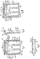
- FIG. 1-3 shows an air distributor 12, or a scoop, with its most important components, which is used in a commercial vehicle body according to an embodiment of the invention.
- the air distributor 12 has a housing 23 with a lower part 23a, an upper part 23b and two side parts 23c.
- the housing 23 can be made of sheet metal or plastic.
- the end faces of the housing 23 are open and form an inlet area 13b and an outlet area 13a, through which air can flow into or out of the air distributor 12.
- the invention is not limited to the guidance or air conditioning of air, but can also be used generally for the guidance or air conditioning of gas, for example ripening gases for fruits or gases which delay ripening, for example nitrogen.
- gas for example ripening gases for fruits or gases which delay ripening, for example nitrogen.
- the invention also extends to commercial vehicle bodies which, instead of a cooling or heating unit, use other conveying means, for example a fan, in which the temperature of the air or the gas is not important. In general, due to the reduced flow losses, an improved distribution of the medium in the cargo hold can be achieved, so that the goods located therein are uniformly flushed with air or gas.
- the air distributor 12 has a plurality of distributor channels 15.
- the distribution channels 15 are formed by webs 24 which are fastened between the lower part 23a and the upper part 23b of the housing.
- the webs 24 and thus the distribution channels 15 are arranged in a fan-like manner in the air distributor 12.
- the distance between adjacent webs 24 or the channel cross section changes and increases in the present example in the direction of flow, ie with increasing distance from the cooling unit 10 '.
- six distribution channels 15 are provided. Another number, for example three, four, five or even more than six distribution channels 15 is possible.
- the number of distributor channels 15 can depend on the width of the structure and on the number of outlet channels 17a, 17b of the air outlet device 14 shown in the remaining figures, which adjoins the air distributor 12.
- the distribution channels, 15 only in To arrange flow direction rear area of the air distributor 12, in particular in the outlet area 13a.
- the front area of the air distributor 12 in the direction of flow, ie the entry area 13b, can be free of installation in the interest of a simple construction. This means that the air blown into the air distributor 12 by the unit or generally by the conveying means enters the inlet area 13b and is distributed in the outlet area 13a to the different outlet channels 17a, 17b due to the distributor channels 15.
- the distribution channels 15 extend into the inlet area 13b, specifically up to the open end of the air distributor on the inlet side. This embodiment is particularly preferred in view of the efficiency of the air distributor 12.
- the distribution channels 15 are arranged axially symmetrically.
- the axially symmetrical arrangement of the distribution channels 15 is provided for a cooling unit 10 ′ or generally a conveying means 10, the outlet area 11 b of which is arranged centrally in the front wall 26.
- the distributor channels 15 asymmetrically, for example by arranging the distributor channels laterally offset in the inlet region 13b of the conveying means 10 with respect to the central axis of the air distributor 12. This results in an arrangement of the distribution channels 15, in which the distribution channels 15 in the outlet area 13a of the air distributor 12 are axially symmetrical (as in FIG Figure 1 )) and are laterally offset in the inlet area 13b (deviating from Figure 1 ).
- This embodiment of the air distributor 12 is provided for cooling units 10 ′ or generally for conveying means 10, the outlet area 11 b of which is not arranged centrally in the front wall 26.
- the position of the distribution channels 15 in the inlet region 13b of the air distributor 12 is adapted to the location of the outlet region 11b of the cooling unit 10 ′ or of the conveying means 10.
- the section of the distributor channels 15 in the outlet region 13a of the air distributor 12 which is arranged axially symmetrically with respect to the center line of the air distributor 12 in the interest of fanning out the air flow as broadly as possible, as in FIG Figure 1 shown.
- the horizontal extension of the air distributor 12 on the outlet side is greater than the horizontal extension on the inlet side.
- the width of the air distributor 12, ie its horizontal extent in the inlet region 13b, is adapted to the width of the outlet region 11b of the conveying means 10 or of the unit 10 '.
- the width of the air distributor 12 in the outlet area 13a is roughly adapted to the width of the structure, but at least wider than the horizontal extent on the inlet side. This creates the prerequisite that the air fed centrally from the unit 10 ′ into the air distributor 12 is distributed over a greater width than was previously the case without there being any cooling losses, since the air distributor 12 has a laterally closed housing 23 having distribution channels 15.
- the fan-like arrangement of the distribution channels 15 is adapted to the widening of the air distributor 12 in the flow direction.
- the vertical extension that is to say the height of the air distributor 12
- the height of the inlet area 13b of the air distributor 12 is adapted approximately to the height of the outlet area 11b of the unit 10.
- the height of the outlet area 13a of the air distributor 12 is adapted to the height of the air outlet device 14, specifically the height of the outlet channels 17a, 17b, which are shown in the remaining figures. Due to the vertical narrowing of the air distributor 12 in the direction of flow, a nozzle effect is generated which contributes to the cooling air or generally the medium to be distributed being conveyed as far as possible into the interior of the cargo hold, in particular up to the rear wall.
- the air distributor 12 has a double-curved side profile 16, in particular an S-shaped side profile 16.
- the lower part 23a has two curvatures of opposite cross-section, that is to say a convex bend, which is followed by a concave bend.
- the upper part 23b is curved in accordance with the lower part 23a, but with smaller radii of curvature, which results in the different inlet and outlet heights.
- the contour of the side parts 23c corresponds to the cross-sectional profile of the lower part 23a and of the upper part 23b, so that overall there is a side profile 16 with double curvature for the air distributor 12.
- the side profile 16 of the air distributor 12 is designed such that the inlet region 13b is arranged lower than the outlet region 13a in the installed state. This results in a particularly favorable flow-wise transition from the unit 10 'to the air outlet device 14, so that the air is guided from the unit 10' to the air outlet device 14 with low friction losses. Flatter or steeper curvatures to adapt to different height differences between the unit 10 'and the air outlet device 14 are possible.
- Fig. 4 represents the air distributor 12 according to the Figures 1-3 in the installed state. It can be seen that the air distributor 12 is arranged between the cooling unit 10 'and the air outlet device 14.
- the lower inlet area 13b of the air distributor 12 is connected to the outlet area 11b of the cooling unit 10 '.
- the outlet area 13a of the air distributor 12 is connected to the air outlet device 14.
- This comprises several outlet channels 17a, 17b.
- six outlet channels 17a, 17b corresponding to the number of distribution channels 15 are provided.
- Another number of outlet channels 17a, 17b is possible, for example three, four or five or even more than six outlet channels 17a, 17b.
- the outlet channels 17a, 17b are designed as flexible air hoses which are attached to the roof 25 of the structure. It is also possible to use rigid outlet channels, for example sheet metal guides, instead of the flexible hoses.
- a plurality of outlet openings 18a, 18b are arranged in the outlet channels 17a, 17b, the diameter of which increases with increasing distance from the air distributor 12, i.e. becomes larger in the direction of flow.
- the air outlet device 14 is constructed in such a way that a plurality of outlet channels 17a, 17b are arranged next to one another essentially in one plane parallel to the roof 25.
- a plurality of internally arranged outlet channels 17a are arranged between lateral outlet channels 17b.
- the internally arranged outlet channels 17a are wider than the laterally arranged outlet channels 17b.
- the lateral outlet channels 17b also have a partially inclined underside, as in particular in FIG Fig. 9 shown.
- the underside is at least partially, starting from a horizontal plane, which is defined by the underside of the outlet channels 17a arranged on the inside, obliquely upwards towards the roof, so that the outlet openings 18b provided therein are also arranged obliquely. This results in an outward flow of the cooling air emerging from the outlet openings 18b in the direction of the side walls.
- the suction area of the cooling unit 10 ' that is to say the area upstream of the cooling unit 10' in the flow direction, is explained below.
- a return system 30 is provided which is closed at the side and is tightly connected to the inlet area 11a of the cooling unit 10' or the conveying means 10.
- the return system has essentially vertically arranged guide channels 18 which are formed in or on the front wall 26 and are arranged upstream of the inlet area 11a of the cooling or heating unit 10.
- the guide channels can either be integrated into the front wall 26 or be placed thereon. In the latter case, the guide channels are formed by hat profiles or Z profiles, which are attached to the front wall, for example screwed to it.
- the guide channels 18 are connected to the cooling unit 10, the air to be cooled or the medium to be cooled being fed through the guide channels 18 to the cooling unit 10 via its inlet area 11a.
- the guide channels 18 are delimited towards the cargo hold 19 by a plate 20 or generally by at least one plate element, in which entry openings 21a are formed, which are connected to the guide channels 18.
- the plate 20 is firmly connected to the hat profiles or Z profiles and is thus spaced from the front wall 26.
- the plate 20 forms, together with the guide channels 18 and the front wall 26, a tightly closed return system 30 which is tightly connected to the cooling unit 10 or the conveying means.
- the return air is therefore supplied to the cooling unit 10 essentially without loss from the cargo hold via the return system.
- the plate 20 covers the entire suction area and is sealed against the unit 10 ′, so that the air to be cooled is sucked in exclusively through the inlet openings 21a in the plate 20.
- the inlet openings 21a are arranged in the bottom area of the structure, specifically on the lower edge 28 of the plate 20.
- the sides of the plate 20 are angled and each form a vertical side area 22 which is arranged obliquely.
- the side region 22 extends from the vertical plane determined by the plate 20 obliquely forward to the front wall 26 and closes tightly therewith.
- further inlet openings 21b are formed, which are arranged vertically in a row, the diameter of the inlet openings 21b increasing with increasing distance from the air distributor 12.
- An angled transition region 29 is arranged between the upper edge 27 of the plate 20 and the vertical side regions 22 and tapers towards the cooling unit 10 '.
- the transition area 29 lies close to the front wall 26 and connects the vertical side area 22 to the entry area 11a of the cooling unit 10 '.
- the inlet openings 21b in the side region 22 of the return system 30 serve to suck in return air in the region of the side walls of the body, the inlet openings becoming larger as the distance from the cooling unit 10 'increases 21b ensures that a larger amount of return air is drawn in near the floor than near the cooling unit 10 '. This favors the return flow of the return air along the side walls of the body, without large amounts of cold return air being drawn in from the upper area of the cargo hold.
- the plate 20 can be made telescopic.
- the plate 20 can be divided into two in the horizontal direction and comprise two or more plate elements.
- the two plate elements overlap vertically, the plate element arranged higher being arranged in such a way that the entire suction area covers and the return system 30 seals tightly with the application area 11 a of the cooling unit 10 ′ or the conveying means 10.
- the degree of overlap depends on the maximum construction height that the system is to be equipped with.
- the air located in the cargo hold near the floor is sucked in through the inlet openings 21a in the plate 20 and rises behind the plate 20 through the guide channels 18 up to the inlet region 11a of the cooling unit 10 '.
- the air is sucked in laterally through the vertical and obliquely arranged further inlet openings 21b of the side region 22 of the plate 20, as shown by the arrows II.
- the air sucked in from the side is also conducted upward via the guide channels 18 to the cooling unit 10 '.
- the cooled air exits the unit 10 'and into the air distributor 12 (arrows III).
- the cooling air is distributed through the distributor channels 15 to the various outlet channels 17a, 17b and then sinks down through the outlet openings 18a, 18b into the cargo hold (arrows IV).
- the cooling air is sucked in near the ground ( Fig. 13 ), so that a cooling air circuit is formed overall.
- the exemplary embodiment explained above offers the advantage that the cooling air conveyed by the cooling unit 10 ′ is distributed uniformly to different outlet channels 18a, 18b arranged next to one another, without any appreciable flow losses occurring.
- the air distributor 12 serves this purpose, in particular the distribution channels 15 arranged in the air distributor 12.
- a further particular advantage of the invention results from the combination of this air distributor 12 with the return system 30, which is sealed at the top and is closed at the side.
- the inlet openings 21a in the bottom region of the Plate 20 promotes the formation of a cooling air circuit or a cooling air circulation in the cargo hold and prevents the unit from icing up.
- the aforementioned return system 30 can also be used independently of the air distributor 12.
- the invention can also be applied to commercial vehicle bodies which have an air or gas conveying means without an air conditioning function, for example a fan for forming an air flow in the cargo hold. Such designs are included in the invention.
- the invention can also be used in open systems in which the medium blown into the cargo hold, for example nitrogen as an anti-ripening gas or hot air, is not recycled but is discharged.
- the medium blown into the cargo hold for example nitrogen as an anti-ripening gas or hot air
Landscapes
- Engineering & Computer Science (AREA)
- Physics & Mathematics (AREA)
- Thermal Sciences (AREA)
- Mechanical Engineering (AREA)
- Chemical & Material Sciences (AREA)
- Combustion & Propulsion (AREA)
- General Engineering & Computer Science (AREA)
- Health & Medical Sciences (AREA)
- Public Health (AREA)
- Transportation (AREA)
- Devices That Are Associated With Refrigeration Equipment (AREA)
- Air-Conditioning For Vehicles (AREA)
Description
- Die Erfindung bezieht sich auf einen Nutzfahrzeugaufbau mit den Merkmalen des Oberbegriffs des Anspruchs 1. Die Erfindung bezieht sich ferner auf ein Nutzfahrzeug mit einem derartigen Aufbau. Siehe
JP 11 201618 A - Für den Transport von verderblichen Lebensmitteln, die tiefgekühlt in der Kette von Erzeuger, Verarbeiter und Verkäufer transportiert werden müssen, wie auch für den Transport von kälteempfindlichen Waren, sind isolierte Kofferaufbauten bekannt. Die von der Kühlmaschine gelieferte gekühlte Luft wird aus einer Austrittöffnung ins Innere des Aufbaus geblasen. Dabei kommt es darauf an, dass ein möglichst gleichmäßiges Temperaturprofil über die gesamte Aufbaulänge und -breite eingestellt werden kann.
- Dazu wird die Kühlluft entweder in einzelne Luftschläuche bzw. Kanäle oder auf ein unter dem Dach des Aufbaus gespanntes Tuch geblasen, wodurch eine möglichst gleichmäßige Verteilung der Kühlluft im Frachtraum erreicht wird.
- Ein Beispiel für die letztere Konstruktion ist in der
DE 100 29 355 A1 gegeben, die auf die Anmelderin zurückgeht. Darin ist ein isolierter Kofferaufbau beschrieben, in dessen Vorderwand ein Kühlaggregat integriert ist. Das Kühlaggregat saugt Luft aus dem Frachtraum an, kühlt diese und bläst dann die gekühlte Luft in Dachnähe auf ein unter das Dach gespannte Tuch bzw. Segel. Damit wird vermieden, dass die kalte Luft in der Nähe des Kühlaggregats, d.h. im vorderen Bereich des Aufbaus nach unten sinkt und eine ausreichende Menge an Kühlluft in den hinteren Bereich des Aufbaus gelangt. Durch das unter das Dach des Aufbaus gespannte Segel wird die Luft zum hinteren Ende des Aufbaus, sowie zu den Seiten hin abgelenkt bzw. geführt. Die an den Seitenwänden bzw. der Rückwand des Aufbaus nach unten sinkende Luft strömt in Bodennähe zur Vorderwand zurück und wird dort vom Kühlaggregat angesaugt. Dadurch entsteht ein Kühlluftkreislauf, der zu einer verbesserten Temperaturverteilung im Frachtraum führt. - Aufgrund von Verwirbelungen verliert die Kühlluft allerdings an Geschwindigkeit, so dass die zur Verfügung stehende Kühlluftmenge nicht ausreichend über die Frachtraumlänge bis zur Rückwand gelangt.
- Ein anderes Beispiel für einen isolierten Kofferaufbau mit Kühlluftzirkulation ist in der
DE 86 30 333 U1 offenbart, die ebenfalls auf die Anmelderin zurückgeht. - Dieser Kofferaufbau weist anstelle des unter dem Dach gespannten Tuches mehrere Kühlluftkanäle auf, die am Dach des Aufbaus zwischen Aufhängerohren befestigt sind und Öffnungen an deren Unterseite aufweisen, durch die die Kühlluft nach unten in den Frachtraum absinken kann. Bei diesem Kühlluftsystem ist eine Platte an der Vorderwand mit einem Spalt angeordnet, durch den Luft aus dem Frachtraum angesaugt und zum Kühlaggregat geleitet wird. Die Unterkante der Platte ist dabei vom Boden beabstandet, so dass die Luft über die gesamte Plattenbreite in den Spalt einströmt.
- Die Platte bildet somit einen nach unten verlaufenden Führungskanal, der seitlich offen ist. Beim Ansaugen verwirbelt die Luft hinter der Platte, wodurch es zu Ansaugverlusten kommt.
- Ein Beispiel für einen gattungsgemäßen Nutzfahrzeugaufbau mit Kühlsystem ist in der
DE 297 12 740 U1 offenbart. Bei dieser Anordnung ist ein Luftverteiler vorgesehen, der von einem Kühlaggregat mit Luft versorgt wird. An den Luftverteiler sind Luftkanalplanenstreifen zur Bildung von Luftkanälen angeschlossen, die unter dem Dach des Frachtraumes befestigt sind. Durch die damit gebildeten Luftkanäle wird die Kühlluft im Frachtraum verteilt. Zum Aufbau des Luftverteilers ist der vorstehend genannten Druckschrift nur zu entnehmen, dass dieser zwei Austrittsöffnungen aufweist, an die zwei Luftkanäle angeschlossen sind. Das bedeutet, dass die Versorgung des Frachtraums mit Kühlluft nur durch zwei Kühlkanäle erfolgt. Eine gleichmäßige Verteilung der Kühlluft bis zu den Seitenwänden ist mit diesem Kühlsystem nicht möglich. - Der Erfindung liegt die Aufgabe zugrunde, einen Nutzfahrzeugaufbau anzugeben, der eine Luft- oder Gasführung mit möglichst geringen Strömungsverlusten ermöglicht. Ferner soll mit der Erfindung ein Nutzfahrzeug mit einem derartigen Aufbau angegeben werden.
- Erfindungsgemäß wird diese Aufgabe durch einen Nutzfahrzeugaufbau gemäß Anspruch 1, sowie durch ein Nutzfahrzeug gemäß Anspruch 12 gelöst.
- Die Erfindung beruht auf dem Gedanken, einen Nutzfahrzeugaufbau mit einem Luft- oder Gasfördermittel vorzusehen, das einen Eintrittsbereich und einen Austrittsbereich aufweist, wobei dem Austrittsbereich ein Luftverteiler und diesem eine Luftaustrittseinrichtung nachgeordnet ist. Erfindungsgemäß weist der Luftverteiler mehrere Verteilerkanäle auf, die fächerartig mit der Luftaustrittseinrichtung verbunden sind.
- Die Verteilerkanäle bieten die Voraussetzung dafür, dass die Luft, bzw. das Gas, insbesondere die Kühlluft über die gesamte Breite des Aufbau oder zumindest über einen großen Teil der Aufbaubreite verteilt wird, ohne dass es dabei zu Verlusten aufgrund von Luftverwirbelungen kommt. Damit wird im Fall eines Kühlaggregates als Fördermittel dessen Kühlleistung besser ausgenutzt und gleichzeitig ein weitgehend homogenes Temperaturprofil im Frachtraum eingestellt, da eine Förderung der Luft bis zum rückwärtigen Ende des Aufbaus durch die verringerten Strömungsverluste begünstigt wird.
- Es versteht sich, dass die Erfindung nicht auf die Verteilung von Kühlluft bzw. die Verwendung eines Kühlaggregates eingeschränkt ist, sondern auch die Verteilung von Warmluft bzw. die Verwendung eines Heizaggregates umfasst. Das erfindungsgemäße Prinzip kann generell auf Aufbauten angewandt werden, bei denen es auf eine möglichst verlustfreie Förderung von Luft oder Gas in den Frachtraum ankommt. Beispielsweise kann dies die Förderung von Reifungsgasen oder die Reifung verzögernden Gasen, wie beispielsweise Stickstoff, umfassen. Als Fördermittel kann ein Ventilator eingesetzt werden, wenn eine Klimatisierung der Luft nicht erforderlich ist.
- In diesem Zusammenhang wird darauf hingewiesen, dass der Ausdruck "Luftverteiler" bzw. "Luftaustrittseinrichtung" diese Bauteile nicht auf die Förderung von Luft einschränkt. Vielmehr sind diese Bauteile auch zur Förderung von Gas geeignet. Der Einfachheit halber wird nachfolgend nur auf die Förderung von Luft Bezug genommen, wobei die Förderung von Gasen mitumfasst ist.
- Bei der Erfindung sind die Verteilerkanäle fächerartig, d. h. in Form eines Fächers mit sich ändernden Kanalquerschnitten, im Luftverteiler angeordnet, wodurch die Luft, insbesondere die Kühlluft gezielt auf unterschiedliche Kanäle bzw. allgemein unterschiedliche Bereiche der Luftaustrittseinrichtung verteilt wird.
- Dabei genügt es, wenn die Verteilerkanäle wenigstens in einem Auslassbereich des Luftverteilers angeordnet sind, wodurch die Herstellung vereinfacht wird. Eine besonders einfache Herstellung ergibt sich, wenn ein Einlassbereich des Luftverteilers einbautenfrei ist.
- Es ist auch möglich, die Verteilerkanäle über die gesamte Länge des Luftverteilers (in Strömungsrichtung) anzuordnen. Die Anordnung bzw. Erstreckung der Verteilerkanäle über die gesamte Länge ist besonders bevorzugt, da durch eine sichere Aufteilung des Luftstromes/Gasstromes in mehrere Teilströme und somit eine gute Auffächerung des Luftstromes/Gasstromes in Querrichtung des Aufbaus bewirkt wird.
- Bei einer weiteren Ausführungsform ist die horizontale Erstreckung des Luftverteilers auslassseitig größer als einlassseitig. Das bedeutet, dass der Luftverteiler an die Austrittsmaße des Fördermittels angepasst ist (Einlassseite des Luftverteilers). Auf der gegenüberliegenden Seite (Auslassseite) ist der Luftverteiler breiter ausgebildet, d.h. die horizontale Erstreckung ist größer und kann an die Breite des Aufbaus angepasst sein. Damit ergibt sich ein günstiger Übergang vom Fördermittel auf die Luftaustrittseinrichtung.
- Ferner kann die vertikale Erstreckung des Luftverteilers auslassseitig kleiner als einlassseitig sein. Das bedeutet, dass der Luftverteiler auf der Anschlussseite zum Fördermittel höher baut, als auf der Auslassseite, die mit der Luftaustrittseinrichtung verbunden ist. Dadurch erfolgt ein strömungstechnisch günstiger Übergang vom Fördermittel auf die Luftaustrittseinrichtung.
- Der Luftverteiler kann ein doppelt gekrümmtes Seitenprofil aufweisen, wodurch unterschiedliche Höhenlagen des Austrittsbereiches des Fördermittels und der Luftaustrittseinrichtung überbrückt werden, ohne dass dabei signifikante Strömungsverluste auftreten.
- Bei einer weiteren bevorzugten Ausführungsform weist die Luftaustrittseinrichtung mehrere Austrittskanäle mit Austrittsöffnungen auf, wobei die Austrittsöffnungen in den seitlichen Austrittskanälen schräg angeordnet sind. Dadurch wird eine günstige Anströmung der Seitenwände des Aufbaus erreicht, so dass die in diesem Bereich absinkende Kühlluft an den Seitenwänden entlang geleitet wird.
- Um eine möglichst gleichmäßige Verteilung der Luft bzw. des Gases, insbesondere der Kühlluft über die gesamte Aufbaulänge zu erreichen, steigt der Durchmesser der Austrittsöffnung mit zunehmendem Abstand vom Luftverteiler.
- Erfindungsgemäß ist der Eintrittsbereich des Luft- oder Gasfördermittels mit einem Rückführsystem dicht verbunden, das seitlich geschlossen ist. Dieses hat den Vorteil, dass die Rückluft gesammelt dem Fördermittel zugeführt wird, ohne dass es dabei zu nennenswerten Ansaugverlusten kommt. Ein Entweichen der Rückluft aus dem Rückführsystem nach oben sowie ein übermäßig starkes Ansaugen von Rückluft in der unmittelbaren Nähe des Aggregats wird daher im Wesentlichen vermieden.
- Für die Dichtigkeit des Rückführsystems genügt es, dass keine nennenswerten Rückluftmengen entweichen können. Eine hermetische Abdichtung des Systems ist nicht erforderlich.
- Die seitlich geschlossene Ausführung des Rückführsystems bedeutet, dass das Rückführsystem in Längsrichtung des Aufbaues bzw. im Wesentlichen senkrecht zur Vorderwand abgeschlossen ist. Die seitlich geschlossene Anordnung muss nicht dicht sein. Vielmehr ist es möglich, dass der Seitenbereich des Rückführsystems an mehreren diskreten Stellen einzelne Öffnungen, beispielsweise Bohrungen aufweist.
- Das Rückführsystem weist mehrere im Wesentlichen senkrecht angeordnete Leitkanäle auf, die mit dem Eintrittsbereich des Luft- oder Gasfördermittels verbunden sind. Durch die Unterteilung des Rückführsystems in mehrere Leitkanäle wird die Stabilität des Rückführsystems verbessert.
- Vorzugsweise weist das Rückführsystem Eintrittsöffnungen auf, die im Bodenbereich des Nutzfahrzeugaufbaus ausgebildet und den Leitkanälen zugeordnet sind.
- Diese Anordnung hat den Vorteil, dass im Fall eines Kühlaggregates als Fördermittel die aus dem Nahbereich des Kühlaggregates zurückströmende Luft, die zwangsläufig etwas kälter ist, als die aus entfernteren Bereichen zurückströmende Luft an definierten Stellen, d.h. über die Eintrittsöffnungen angesaugt wird. Insbesondere wenn die Eintrittsöffnun-< gen im Bodenbereich des Nutzfahrzeugaufbaus angeordnet sind, wird sicher vermieden, dass das Kühlaggregat vereist.
- Ein vertikaler Seitenbereich des Rückführsystems kann schräg angeordnet sein, wobei in dem Seitenbereich Eintrittsöffnungen ausgebildet sind. Durch die schräge Anordnung des vertikalen Seitenbereiches wird vermieden, dass die in diesem Bereich vorgesehenen Eintrittsöffnungen durch Frachtgut versehentlich verstellt bzw. verschlossen werden. Der Durchmesser der Eintrittsöffnungen des Seitenbereiches kann mit zunehmendem Abstand vom Luftverteiler größer werden.
- Gemäß einem unabhängigen Aspekt ist ein Nutzfahrzeugaufbau mit einem Luft- oder Gasfördermittel vorgesehen, das einen Eintrittsbereich und einen Austrittsbereich aufweist, wobei dem Eintrittsbereich ein Rückführsystem vorgeordnet ist. Das Rückführsystem ist seitlich geschlossen und mit dem Eintrittsbereich dicht verbunden. Dieser gegen die
DE 86 30 333 U1 abgegrenzte Nutzfahrzeugaufbau hat den Vorteil, dass durch die geschlossene Bauweise des Rückführsystems Ansaugverluste vermieden werden, so dass ein Großteil bzw. die gesamte angesaugte Rückluft dem Luft- oder Gasföidermittel zugeführt wird. Das vorstehend genannte Rückführsystem bietet also eine weitere Möglichkeit, die Luft- oder Gasführung des Nutzfahrzeugaufbaus mit möglichst geringen Strömungsverlusten durchzuführen. Insofern wird das vorstehend genannte Rückführsystem sowohl in Verbindung mit dem Luftverteiler als auch in unabhängiger Form beansprucht. - Nachfolgend wird die Erfindung anhand eines Ausführungsbeispieles mit weiteren Einzelheiten unter Bezug auf die beigefügten schematischen Zeichnungen erläutert.
- In diesen zeigen:
- Fig. 1
- eine perspektivische Ansicht eines Luftverteilers, der in einem Nutzfahrzeugaufbau nach einem erfindungsgemäßen Ausführungsbeispiel eingebaut ist;
- Fig. 2
- eine Seitenansicht des Luftverteilers gemäß
Fig. 1 ; - Fig. 3
- eine Draufsicht auf den Luftverteiler gemäß
Fig. 1 ; - Fig. 4
- eine perspektivische Ansicht des Frachtraumes eines Nutzfahrzeugaufbaus mit einem Luftverteiler gemäß
Fig. 1 , wobei im Interesse der Übersichtlichkeit eine Seitenwand, die Rückwand und der Boden nicht dargestellt sind; - Fig. 5
- eine Seitenansicht des Frachtraumes gemäß
Fig. 4 ; - Fig. 6
- eine Vorderansicht einer Vorderwand gemäß
Fig. 4 mit einem Luftverteiler gemäßFig. 1 ; - Fig. 7
- eine Seitenansicht der Vorderwand gemäß
Fig. 5 ; - Fig. 8
- eine Draufsicht auf die Vorderwand gemäß
Fig. 5 ; - Fig. 9
- eine perspektivische Ansicht gemäß
Fig. 5 ; - Fig. 10
- eine Seitenansicht des Luftverteilers gemäß
Fig. 1 mit Luftaustrittseinrichtung; - Fig. 11
- eine perspektivische Ansicht des Luftverteilers gemäß
Fig. 10 von schräg oben; - Fig. 12
- eine perspektivische Ansicht des Luftverteilers gemäß
Fig. 10 von schräg unten; und - Fig. 13
- eine Ansicht des Frachtraums gemäß
Fig. 5 , wobei die Luftströmung im Frachtraum durch Pfeile verdeutlicht ist. - In den
Figuren 1 - 3 ist ein Luftverteiler 12, bzw. eine Hutze, mit seinen wichtigsten Bauteilen dargestellt, der bei einem Nutzfahrzeugaufbau nach einem erfindungsgemäßen Ausführungsbeispiel zum Einsatz kommt. Der Luftverteiler 12 weist ein Gehäuse 23 mit einem Unterteil 23a, einem Oberteil 23b, sowie zwei Seitenteilen 23c auf. Das Gehäuse 23 kann aus Blech oder Kunststoff hergestellt sein. Die Stirnseiten des Gehäuses 23 sind geöffnet und bilden einen Einlassbereich 13b sowie einen Auslassbereich 13a, durch die Luft in den Luftverteiler 12 einströmen bzw. ausströmen kann. - Die Erfindung ist nicht auf die Führung bzw. Klimatisierung von Luft beschränkt, sondern kann auch generell zur Führung bzw. Klimatisierung von Gas verwendet werden, beispielsweise von Reifungsgasen für Früchte oder die Reifung verzögernde Gasen, beispielsweise Stickstoff. Die Erfindung erstreckt sich auch auf Nutzfahrzeugaufbauten, die anstelle eines Kühl- oder Wärmeaggregates andere Fördermittel, beispielsweise einen Ventilator verwenden, bei denen es auf eine Temperierung der Luft bzw. des Gases nicht ankommt. Generell kann aufgrund der verringerten Strömungsverluste eine verbesserte Verteilung des Mediums im Frachtraum erreicht werden, so dass die darin befindlichen Waren bzw. Güter gleichmäßig mit Luft bzw. Gas umspült werden.
- Wie in
Fig. 1 dargestellt, weist der Luftverteiler 12 mehrere Verteilerkanäle 15 auf. Die Verteilerkanäle 15 sind durch Stege 24 gebildet, die zwischen dem Unterteil 23a und dem Oberteil 23b des Gehäuses befestigt sind. Die Stege 24 und somit die Verteilerkanäle 15 sind im Luftverteiler 12 fächerartig angeordnet. Der Abstand zwischen benachbarten.Stegen 24 bzw. der Kanalquerschnitt ändert sich und nimmt im vorliegenden Beispiel in Strömungsrichtung, d.h. mit zunehmendem Abstand vom Kühlaggregat 10' zu. - Im vorliegenden Ausführungsbeispiel sind sechs Verteilerkanäle 15 vorgesehen. Eine andere Anzahl, beispielsweise drei, vier, fünf oder auch mehr als sechs Verteilerkanäle 15 ist möglich. Die Anzahl der Verteilerkanäle 15 kann sich nach der Breite des Aufbaus richten sowie nach der Anzahl der in den übrigen Figuren dargestellten Austrittskanälen 17a, 17b der Luftaustritteinrichtung 14, die sich an den Luftverteiler 12 anschließt.
- Es ist möglich, die Verteilerkanäle, 15 nur im in Strömungsrichtung hinteren Bereich des Luftverteilers 12, insbesondere im Auslassbereich 13a anzuordnen. Der in Strömungsrichtung vordere Bereich des Luftverteilers 12, d.h. der Eintrittsbereich 13b kann im Interesse einer einfachen Konstruktion einbautenfrei sein. Das bedeutet, dass die vom Aggregat bzw. allgemein vom Fördermittel in den Luftverteiler 12 eingeblasene Luft gesammelt in den Einlassbereich 13b eintritt und im Auslassbereich 13a aufgrund der Verteilerkanäle 15 auf die unterschiedlichen Austrittskanäle 17a, 17b verteilt wird.
- Um eine sichere und gleichmäßige Aufteilung des Luftstromes in mehrere Teilströme zu gewährleisten, sind die Verteilerkanäle 15 bis in den Einlassbereich 13b, konkret bis zur geöffneten einlassseitigen Stirnseite des Luftverteilers erstreckt. Diese Ausführung ist im Hinblick auf die Effizienz des Luftverteilers 12 besonders bevorzugt.
- Im vorliegenden Ausführungsbeispiel sind die Verteilerkanäle 15 achssymetrisch angeordnet. Die achssymetrische Anordnung der Verteilkanäle 15 ist für ein Kühlaggregat 10' bzw. generell ein Fördermittel 10 vorgesehen, dessen Austrittsbereich 11b mittig in der Vorderwand 26 angeordnet ist. Daneben ist es auch möglich, die Verteilerkanäle 15 asymetrisch anzuordnen, beispielsweise indem die Verteilerkanäle im Einlassbereich 13b des Fördermittels 10 bezogen auf die Mittelachse des Luftverteilers 12 seitlich versetzt angeordnet sind. Daraus ergibt sich eine Anordnung der Verteilerkanäle 15, bei der die Verteilkanäle 15 im Auslassbereich 13a des Luftverteilers 12 achssymetrisch (wie in
Figur 1 ) dargestellt) und im Einlassbereich 13b seitlich versetzt angeordnet sind (abweichend vonFigur 1 ). Diese Ausführungsform des Luftverteilers 12 ist für Kühlaggregate 10' bzw. allgemein für Fördermittel 10 vorgesehen, deren Austrittsbereich 11b nicht mittig in der Vorderwand 26 angeordnet ist. - Generell wird die Position der Verteilerkanäle 15 im Einlassbereich 13b des Luftverteilers 12 an die Ortslage des Austrittsbereich 11b des Kühlaggregates 10' bzw. des Fördermittels 10 angepasst. Das bedeutet, dass der Abschnitt der fächerartig angeordneten Verteilerkanäle 15 mit kleinem Kanalquerschnitt, also der im Einlassbereich 13b des Luftverteilers 12 angeordnete Abschnitt der Verteilerkanäle 15 mittig oder seitlich versetzt bezogen auf die Mittellinie des Luftverteilers 12 angeordnet sein kann.
- Dasselbe gilt für den Abschnitt der Verteilerkanäle 15 im Auslassbereich 13a des Luftverteilers 12, der im Interesse einer möglichst breiten Auffächerung des Luftstromes achssymetrisch bezogen auf die Mittellinie des Luftverteilers 12 angeordnet ist, wie in
Figur 1 dargestellt. Daneben ist es auch denkbar, die Verteilerkanäle 15 im Auslassbereich 13a des Luftverteilers 12 auf einen bestimmten Teilbereich des Frachtraumes zu richten, so dass eine außermittige Anordnung der Verteilerkanäle 15 im Auslassbereich 13a des Luftverteilers 12 möglich ist. - Wie in den
Figuren 1 und 3 zu erkennen, ist die horizontale Erstreckung des Luftverteilers 12 auslassseitig größer als die horizontale Erstreckung auf der Einlassseite. Dabei ist die Breite des Luftverteilers 12, d.h. dessen horizontale Erstreckung im Einlassbereich 13b an die Breite des Austrittsbereichs 11b des Fördermittels 10 bzw. des Aggregats 10' angepasst. Die Breite des Luftverteilers 12 im Auslassbereich 13a ist in etwa an die Breite des Aufbaus angepasst, zumindest jedoch breiter als die horizontale Erstreckung auf der Einlassseite. Damit wird die Voraussetzung geschaffen, dass die zentral vom Aggregat 10' in den Luftverteiler 12 eingespeiste Luft auf eine größere Breite verteilt wird, als dies bisher der Fall war, ohne dass es dabei zu Kühlverlusten kommt, da der Luftverteiler 12 ein seitlich geschlossenes Gehäuse 23 mit Verteilerkanälen 15 aufweist. InFig. 1 ist in diesem Zusammenhang zu erkennen, dass die fächerartige Anordnung der Verteilerkanäle 15 an die Verbreiterung des Luftverteilers 12 in Strömungsrichtung angepasst ist. - In den
Figuren 1 und 2 ist dargestellt, dass die vertikale Erstreckung, also die Höhe des Luftverteilers 12 auslassseitig kleiner ist als einlassseitig. Dabei ist die Höhe des Einlassbereiches 13b des Luftverteilers 12 in etwa an die Höhe des Austrittsbereichs 11b des Aggregats 10 angepasst. Die Höhe des Auslassbereichs 13a des Luftverteilers 12 ist an die Höhe der Luftaustrittseinrichtung 14, konkret die Höhe der Austrittskanäle 17a, 17b angepasst, die in den übrigen Figuren dargestellt sind. Durch die in Strömungsrichtung erfolgende vertikale Verengung des Luftverteilers 12 wird ein Düseneffekt erzeugt, der dazu beiträgt, dass die Kühlluft bzw. generell das zu verteilende Medium möglichst weit ins Innere des Frachtraums, insbesondere bis zur Rückwand gefördert wird. - In den
Figuren 1 und 2 ist ferner dargestellt, dass der Luftverteiler 12 ein doppelt gekrümmtes Seitenprofil 16, insbesondere ein S-förmiges Seitenprofil 16 aufweist. Das bedeutet, dass das Unterteil 23a zwei im Querschnitt gegenläufige Krümmungen aufweist, also eine konvexe Biegung, an die sich eine konkave Biegung anschließt. Das Oberteil 23b ist entsprechend dem Unterteil 23a gekrümmt, allerdings mit kleineren Krümmungsradien, wodurch sich die unterschiedlichen Einlass- und Auslasshöhen ergeben. Die Kontur der Seitenteile 23c entspricht dem Querschnittsprofil des Unterteils 23a sowie des Oberteils 23b, so dass sich insgesamt für den Luftverteiler 12 ein Seitenprofil 16 mit doppelter Krümmung ergibt. - Das Seitenprofil 16 des Luftverteilers 12 ist dabei so ausgebildet, dass der Einlassbereich 13b im eingebauten Zustand tiefer als der Auslassbereich 13a angeordnet ist. Dadurch ergibt sich ein strömungstechnisch besonders günstiger Übergang vom Aggregat 10' auf die Luftaustrittseinrichtung 14, so dass die Luft vom Aggregat 10' zur Luftaustrittseinrichtung 14 mit geringen Reibungsverlusten geführt ist. Flachere oder steilere Krümmungen zur Anpassung an unterschiedliche Höhendifferenzen zwischen dem Aggregat 10' und der Luftaustrittseinrichtung 14 sind möglich.
-
Fig. 4 stellt den Luftverteiler 12 gemäß denFiguren 1 - 3 im eingebauten Zustand dar. Dabei ist zu erkennen, dass der Luftverteiler 12 zwischen dem Kühlaggregat 10' und der Luftaustrittseinrichtung 14 angeordnet ist. - Der tiefer angeordnete Einlassbereich 13b des Luftverteilers 12 ist mit dem Austrittsbereich 11b des Kühlaggregats 10' verbunden. Der Auslassbereich 13a des Luftverteilers 12 ist mit der Luftaustrittseinrichtung 14 verbunden. Diese umfasst mehrere Austrittskanäle 17a, 17b. Im vorliegenden Beispiel sind sechs Austrittskanäle 17a, 17b entsprechend der Anzahl der Verteilerkanäle 15 vorgesehen. Eine andere Anzahl von Austrittskanälen 17a, 17b ist möglich, beispielsweise drei, vier oder fünf oder auch mehr als sechs Austrittskanäle 17a, 17b.
- Die Austrittskanäle 17a, 17b sind als flexible Luftschläuche ausgebildet, die am Dach 25 des Aufbaus befestigt sind. Es ist auch möglich, anstelle der flexiblen Schläuche starre Austrittskanäle, beispielsweise Blechführungen zu verwenden.
- In den Austrittskanälen 17a, 17b sind mehrere Austrittsöffnungen 18a, 18b angeordnet, deren Durchmesser mit zunehmendem Abstand vom Luftverteiler 12, d.h. in Strömungsrichtung größer wird. Durch die Austrittsöffnungen 18a, 18b sinkt die Kühlluft nach unten in den Frachtraum ab und umspült die darin befindlichen Güter. Die Luftaustrittseinrichtung 14 ist so aufgebaut, dass mehrere Austrittskanäle 17a, 17b im Wesentlichen in einer Ebene parallel zum Dach 25 nebeneinander angeordnet sind. Dabei sind mehrere innen angeordnete Austrittskanäle 17a zwischen seitlichen Austrittskanälen 17b angeordnet. Die innen angeordneten Austrittskanäle 17a sind breiter als die seitlich angeordneten Austrittskanäle 17b.
- Die seitlichen Austrittskanäle 17b weisen überdies eine teilweise schräg ausgebildete Unterseite auf, wie insbesondere in
Fig. 9 dargestellt. Die Unterseite ist zumindest teilweise, ausgehend von einer horizontalen Ebene, die durch die Unterseite der innen angeordneten Austrittskanäle 17a definiert ist, schräg nach oben zum Dach hin ausgebildet, so dass die darin vorgesehenen Austrittsöffnungen 18b ebenfalls schräg angeordnet sind. Dadurch ergibt sich eine nach außen gerichtete Strömung der aus den Austrittsöffnungen 18b austretenden Kühlluft in Richtung der Seitenwände. - Nachfolgend wird der Ansaugbereich des Kühlaggregates 10', also der dem Kühlaggregat 10' in Strömungsrichtung vorgeordnete Bereich erläutert.
- Im Ansaugbereich des Kühlaggregates 10' bzw. des Fördermittels 10 ist ein Rückführsystem 30 vorgesehen, das seitlich geschlossen und mit dem Eintrittsbereich 11a des Kühlaggregates 10' bzw. des Fördermittels 10 dicht verbunden ist.
- Das Rückführsystem weist im Wesentlichen senkrecht angeordnete Leitkanäle 18 auf, die in oder an der Vorderwand 26 ausgebildet und dem Eintrittsbereich 11a des Kühl- bzw. Wärmeaggregates 10 vorgeordnet sind. Die Leitkanäle können entweder in die Vorderwand 26 integriert oder auf dieser aufgesetzt sein. Im letzteren Fall sind die Leitkanäle durch Hutprofile oder Z-Profile ausgebildet, die an der Vorderwand befestigt, beispielsweise mit dieser verschraubt sind. Die Leitkanäle 18 sind mit dem Kühlaggregat 10 verbunden, wobei die zu kühlende Luft bzw. das zu kühlende Medium durch die Leitkanäle 18 dem Kühlaggregat 10 über dessen Eintrittsbereich 11a zugeführt wird. Die Leitkanäle 18 sind zum Frachtraum 19 hin durch eine Platte 20 bzw. allgemein durch wenigstens ein Plattenelement begrenzt, in der bzw. dem Eintrittsöffnungen 21a ausgebildet sind, die mit den Leitkanälen 18 verbunden sind. Die Platte 20 ist mit den Hutprofilen bzw. Z-Profilen fest verbunden und somit von der Vorderwand 26 beabstandet. Durch die Ausbildung mehrerer Leitkanäle 18, die durch die Hutprofile bzw. Z-Profile begrenzt sind, wird eine stabile und robuste Wandkonstruktion geschaffen, die der Belastung durch Frachtgüter Stand hält.
- Die Platte 20 bildet zusammen mit den Leitkanälen 18 und der Vorderwand 26 ein dicht abgeschlossenes Rückführsystem 30, das mit dem Kühlaggregat 10 bzw. dem Fördermittel dicht verbunden ist. Die Rückluft wird daher im Wesentlichen verlustfrei aus dem Frachtraum über das Rückführsystem dem Kühlaggregat 10 zugeführt.
- Die Platte 20 bedeckt den gesamten Ansaugbereich und ist gegen das Aggregat 10' abgedichtet, so dass die zu kühlende Luft ausschließlich über die Eintrittsöffnungen 21a in der Platte 20 angesaugt wird. Die Eintrittsöffnungen 21a sind dabei im Bodenbereich des Aufbaus angeordnet, konkret an der Unterkante 28 der Platte 20. Die Seiten der Platte 20 sind abgewinkelt und bilden jeweils einen vertikalen Seitenbereich 22, der schräg angeordnet ist. Der Seitenbereich 22 erstreckt sich ausgehend von der durch die Platte 20 bestimmten vertikalen Ebene schräg nach vorne zur Vorderwand 26 hin und schließt mit dieser dicht ab. Im Seitenbereich 22 sind weitere Eintrittöffnungen 21b ausgebildet, die vertikal in einer Reihe angeordnet sind, wobei der Durchmesser der Eintrittsöffnungen 21b mit zunehmendem Abstand vom Luftverteiler 12 größer wird. Zwischen der Oberkante 27 der Platte 20 und den vertikalen Seitenbereichen 22 ist ein abgewinkelter Übergangsbereich 29 angeordnet, der sich zum Kühlaggregat 10' hin verjüngt. Der Übergangsbereich 29 liegt dicht an der Vorderwand 26 an und verbindet den vertikalen Seitenbereich 22 mit dem Eintrittsbereich 11a des Kühlaggregats 10'. Dadurch ist die Platte 20 bzw. das dadurch gebildete Rückführsystem 30 nach oben hin dicht geschlossen, so dass weder Rückluft entweichen noch Kaltluft nachströmen kann.
- Die Eintrittsöffnungen 21b im Seitenbereich 22 des Rückführsystems 30 dienen zur Ansaugung von Rückluft im Bereich der Seitenwände des Aufbaues, wobei durch den mit zunehmendem Abstand vom Kühlaggregat 10' größer werdenden Durchmesser die Eintrittsöffnungen 21b sichergestellt wird, dass eine größere Menge an Rückluft in Bodennähe als in Nähe des Kühlaggregates 10' angesaugt wird. Dadurch wird das Zurückströmen der Rückluft entlang der Seitenwände des Aufbaus begünstigt, ohne dass dabei größere Mengen an kalter Rückluft aus dem oberen Bereich des Frachtraumes angesaugt werden.
- Um das Rückführsystems 30 an unterschiedlichen Aufbauhöhen anzupassen, kann die Platte 20 teleskopierbar ausgebildet sein. Dazu kann die Platte 20 in horizontaler Richtung zweigeteilt sein und zwei oder mehr Plattenelemente umfassen. Die beiden Plattenelemente überlappen vertikal, wobei das höher angeordnete Plattenelement entsprechend der jeweiligen Aufbauhöhe so angeordnet wird, dass der komplette Ansaugbereich überdeckt und das Rückführsystem 30 dicht mit dem Einsatzbereich 11a des Kühlaggregates 10' bzw. des Fördermittels 10 abdichtet. Der Grad der Überlappung richtet sich nach der maximalen Aufbauhöhe, die mit dem System ausgestattet werden soll.
- Die Funktionsweise des vorstehend beschriebenen Nutzfahrzeugaufbaus wird unter Bezug auf die
Fig. 13 näher erläutert. - Wie anhand der Pfeile I zu erkennen, wird die im Frachtraum befindliche Luft in Bodennähe durch die Eintrittsöffnungen 21a in der Platte 20 angesaugt und steigt hinter der Platte 20 durch die Leitkanäle 18 nach oben bis zum Eintrittsbereich 11a des Kühlaggregats 10'. Zusätzlich wird die Luft seitlich durch die vertikalen und schräg angeordneten weiteren Eintrittsöffnungen 21b des Seitenbereichs 22 der Platte 20 angesaugt, wie durch die Pfeile II dargestellt. Die seitlich angesaugt Luft wird ebenfalls über die Leitkanäle 18 nach oben zum Kühlaggregat 10' geleitet. Wie in
Fig. 4 dargestellt, tritt die gekühlte Luft aus dem Aggregat 10' aus und in den Luftverteiler 12 ein (Pfeile III). Im Luftverteiler 12 wird die Kühlluft durch die Verteilerkanäle 15 auf die verschiedenen Austrittskanäle 17a, 17b verteilt und sinkt dann sukzessive durch die Austrittsöffnungen 18a, 18b nach unten in den Frachtraum ab (Pfeile IV). In Bodennähe wird die Kühlluft wieder angesaugt (Fig. 13 ), so dass sich insgesamt ein Kühlluftkreislauf bildet. - Insgesamt bietet das vorstehend erläuterte Ausführungsbeispiel den Vorteil, dass die vom Kühlaggregat 10' geförderte Kühlluft gleichmäßig auf nebeneinander angeordnete verschiedene Austrittskanäle 18a, 18b verteilt wird, ohne dass es dabei zu nennenswerten Strömungsverlusten kommt. Dazu dient der Luftverteiler 12, insbesondere die im Luftverteiler 12 angeordneten Verteilerkanäle 15. Ein weiterer besonderer Vorteil der Erfindung ergibt sich durch die Kombination dieses Luftverteilers 12 mit dem nach oben abgedichteten und seitlich geschlossenen Rückführsystem 30. Insbesondere durch die Anordnung der Eintrittsöffnungen 21a im Bodenbereich der Platte 20 wird die Ausbildung eines Kühlluftkreislaufes bzw. einer Kühlluftzirkulation im Frachtraum begünstigt und ein Vereisen des Aggregats verhindert. Das vorstehend genannte Rückführsystem 30 kann auch unabhängig vom Luftverteiler 12 verwendet werden.
- Die Erfindung kann auch auf Nutzfahrzeugaufbauten angewandt werden, die ein Luft- bzw. Gasfördermittel ohne Klimatisierungsfunktion, beispielsweise einen Ventilator zur Ausbildung einer Luftströmung im Frachtraum aufweisen. Derartige Ausführungen sind von der Erfindung mit umfasst.
- Neben dem vorstehend beschriebenen geschlossenen Kreislauf kann die Erfindung auch bei offenen Systemen eingesetzt werden, bei denen das in den Frachtraum eingeblasene Medium, beispielsweise Stickstoff als Antireifungsgas oder Heizluft nicht rückgeführt, sondern abgelassen wird.
- Ferner wird ein Nutzfahrzeug mit einem vorstehend beschriebenen Aufbau beansprucht.
-
- 10
- Luft- oder Gasfördermittel
- 10'
- Kühlaggregat
- 11a
- Eintrittsbereich
- 11b
- Austrittsbereich
- 12
- Luftverteiler
- 13a
- Auslassbereich
- 13b
- Einlassbereich
- 14
- Luftaustrittseinrichtung
- 15
- Verteilerkanäle
- 16
- Seitenprofil
- 17a, 17b
- Austrittskanäle
- 18
- Leitkanäle
- 18a, 18b
- Austrittsöffnungen
- 19
- Frachtraum
- 20
- Platte
- 21a, 21b
- Eintrittsöffnungen
- 22
- Seitenbereich
- 23
- Gehäuse
- 23a
- Unterteil
- 23b
- Oberteil
- 23c
- Seitenteile
- 24
- Stege
- 25
- Dach
- 26
- Vorderwand
- 27
- Oberkante der Platte
- 28
- Unterkante der Platte
- 29
- Übergangsbereich
- 30
- Rückführsystem
Claims (12)
- Nutzfahrzeugaufbau mit einem Luft- oder Gasfördermittel (10), das einen Eintrittsbereich (11a) und einen Austrittsbereich (11b) aufweist, wobei dem Austrittsbereich (11b) ein Luftverteiler (12) und diesem eine im Bereich des Daches (25) vorgesehene Luftaustrittseinrichtung (14) nachgeordnet ist, wobei der Luftverteiler (12) mehrere Verteilerkanäle (15) aufweist, die mit der Luftaustrittseinrichtung (14) verbunden sind,
dadurch gekennzeichnet, dass
die Verteilerkanäle (15) fächerartig im Luftverteiler (12) angeordnet sind, wobei der Eintrittsbereich (11a) des Luft- oder Gasfördermittels (10) mit einem Rückführsystem (30) dicht verbunden ist, das seitlich geschlossen ist und mehrere im wesentlichen senkrecht angeordnete Leitkanäle (18) aufweist, die mit dem Eintrittsbereich (11a) des Luft- oder Gasfördermittels (10) verbunden sind. - Nutzfahrzeugaufbau nach Anspruch 1
dadurch gekennzeichnet, dass
die Verteilerkanäle (15) wenigstens in einem Auslassbereich (13a) des Luftverteilers (12) angeordnet sind. - Nutzfahrzeugaufbau nach wenigstens einem der Ansprüche 1 oder 2,
dadurch gekennzeichnet, dass
ein Einlassbereich (13b) des Luftverteilers (12) einbautenfrei ist. - Nutzfahrzeugaufbau nach wenigstens einem der vorherigen Ansprüche,
dadurch gekennzeichnet, dass
die horizontale Erstreckung des Luftverteilers (12) auslassseitig größer ist als einlassseitig. - Nutzfahrzeugaufbau nach wenigstens einem der vorherigen Ansprüche,
dadurch gekennzeichnet, dass
die vertikale Erstreckung des Luftverteilers (12) auslassseitig kleiner ist als einlassseitig. - Nutzfahrzeugaufbau nach wenigstens einem der vorherigen Ansprüche,
dadurch gekennzeichnet, dass
der Luftverteiler (12) ein doppelt gekrümmtes Seitenprofil (16) aufweist. - Nutzfahrzeugaufbau nach wenigstens einem der vorherigen Ansprüche,
dadurch gekennzeichnet, dass
die Luftaustrittseinrichtung (14) mehrere Austrittskanäle (17a, 17b) mit Austrittsöffnungen (18a, 18b) aufweist, wobei die Austrittsöffnungen (18b) in den seitlichen Austrittskanälen (17b) schräg angeordnet sind. - Nutzfahrzeugaufbau nach wenigstens einem der vorherigen Ansprüche,
dadurch gekennzeichnet, dass
der Durchmesser der Austrittsöffnungen (18a, 18b) mit zunehmendem Abstand vom Luftverteiler (12) steigt. - Nutzfahrzeugaufbau nach Anspruch 8,
dadurch gekennzeichnet, dass
das Rückführsystem (30) Eintrittsöffnungen (21a) aufweist, die im Bodenbereich des Nutzfahrzeugaufbaus ausgebildet und den Leitkanälen (18) zugeordnet sind. - Nutzfahrzeugaufbau nach wenigstens einem der vorherigen Ansprüche,
dadurch gekennzeichnet, dass
ein vertikaler Seitenbereich (22) des Rückführsystems (30) schräg angeordnet ist, wobei in dem Seitenbereich (22) Eintrittsöffnungen (21b) ausgebildet sind. - Nutzfahrzeugaufbau nach Anspruch 10,
dadurch gekennzeichnet, dass
der Durchmesser der Eintrittsöffnungen (21b) im Seitenbereich (22) mit zunehmendem Abstand vom Luftverteiler (12) steigt. - Nutzfahrzeug mit einem Nutzfahrzeugaufbau nach wenigstens einem der vorhergehenden Ansprüche.
Applications Claiming Priority (1)
| Application Number | Priority Date | Filing Date | Title |
|---|---|---|---|
| DE102006057599.7A DE102006057599B4 (de) | 2006-12-06 | 2006-12-06 | Nutzfahrzeugaufbau und Nutzfahrzeug mit einem derartigen Aufbau |
Publications (4)
| Publication Number | Publication Date |
|---|---|
| EP1930211A2 EP1930211A2 (de) | 2008-06-11 |
| EP1930211A3 EP1930211A3 (de) | 2009-10-07 |
| EP1930211B1 EP1930211B1 (de) | 2016-04-13 |
| EP1930211B2 true EP1930211B2 (de) | 2020-01-15 |
Family
ID=39187542
Family Applications (1)
| Application Number | Title | Priority Date | Filing Date |
|---|---|---|---|
| EP07023584.1A Not-in-force EP1930211B2 (de) | 2006-12-06 | 2007-12-05 | Nutzfahrzeugaufbau und Nutzfahrzeug mit einem derartigen Aufbau |
Country Status (2)
| Country | Link |
|---|---|
| EP (1) | EP1930211B2 (de) |
| DE (1) | DE102006057599B4 (de) |
Families Citing this family (8)
| Publication number | Priority date | Publication date | Assignee | Title |
|---|---|---|---|---|
| GB2456338A (en) * | 2008-01-14 | 2009-07-15 | Ford Global Tech Llc | Air duct for a vehicle air conditioning system |
| US10502475B2 (en) * | 2012-08-22 | 2019-12-10 | Carrier Corporation | Refrigerated container and duct extension |
| EP2888121A1 (de) * | 2012-08-22 | 2015-07-01 | Carrier Corporation | Luftstromzufuhrkanal für einen kühlauflieger |
| EP3695999B1 (de) | 2019-02-15 | 2022-09-07 | Schmitz Cargobull AG | Kofferaufbau für ein nutzfahrzeug |
| EP3695998B1 (de) * | 2019-02-15 | 2022-08-31 | Schmitz Cargobull AG | Kofferaufbau mit luftleiteinrichtung |
| EP3695996B1 (de) * | 2019-02-15 | 2022-07-20 | Schmitz Cargobull AG | Kofferaufbau mit kurzschlusssperre |
| EP3696000A1 (de) | 2019-02-15 | 2020-08-19 | Schmitz Cargobull AG | Kofferaufbau eines nutzfahrzeugs |
| DE102021128294B3 (de) * | 2021-10-29 | 2022-11-17 | Kögel Trailer GmbH | Haltevorrichtung, Isolierpaneel mit einer Haltevorrichtung, Fahrzeugaufbau, insbesondere Kühlfahrzeugaufbau, Verwendung einer solchen Haltevorrichtung |
Citations (1)
| Publication number | Priority date | Publication date | Assignee | Title |
|---|---|---|---|---|
| WO2005113311A1 (en) † | 2004-05-13 | 2005-12-01 | Gunderson, Inc. | Air flow direction in a temperature-controlled railroad freight car |
Family Cites Families (12)
| Publication number | Priority date | Publication date | Assignee | Title |
|---|---|---|---|---|
| GB8624960D0 (en) * | 1986-10-17 | 1986-11-19 | Petter Refrigeration Ltd | Refrigeration of multi-compartmented spaces |
| DE8630333U1 (de) * | 1986-11-12 | 1987-01-08 | F.X. Kögel GmbH & Co Fahrzeugwerke, 7900 Ulm | Kühlaufbau für Lastfahrzeuge |
| GB2282873B (en) | 1993-10-13 | 1997-08-27 | Shipowners Cargo Res Assoc | A method of controlling the temperature of cargo within a container |
| US5807046A (en) * | 1996-02-26 | 1998-09-15 | Onken; Greg | Air return bulkhead |
| DE19831787A1 (de) * | 1997-07-18 | 1999-01-21 | Denso Corp | Kraftfahrzeug-Kühlsystem |
| DE29712740U1 (de) * | 1997-07-18 | 1997-11-27 | Schmitz-Anhänger Fahrzeugbau Gesellschaft mbH & Co, 48341 Altenberge | Luftkanal zur Verteilung von Luft im Frachtraum eines Kraftfahrzeugs |
| JPH11201618A (ja) * | 1998-01-13 | 1999-07-30 | Shinbutsuryuu System Kaihatsu Kyodo Kumiai | 冷凍,冷蔵車におけるエアーコールダクト装置 |
| US6508076B1 (en) * | 2000-02-03 | 2003-01-21 | Thermo King Corporation | Duct system for temperature-controlled cargo containers |
| DE10029355B4 (de) * | 2000-06-15 | 2013-07-11 | Kögel Trailer GmbH & Co. KG | Luftführungseinrichtung für zu klimatisierende Räume, insbesondere von Fahrzeugen, und klimatisierter Raum mit einer derartigen Einrichtung |
| CA2452416C (en) | 2003-12-03 | 2007-05-22 | Sturdy Truck Body (1972) Limited | Hatchling transport trailer |
| US7351136B2 (en) * | 2004-03-25 | 2008-04-01 | Fg Products, Inc. | Air return bulkhead with quick release mounting system |
| WO2006104491A1 (en) | 2005-03-29 | 2006-10-05 | Carrier Corporation | Single piece nozzle cover design and method of manufacture |
-
2006
- 2006-12-06 DE DE102006057599.7A patent/DE102006057599B4/de not_active Withdrawn - After Issue
-
2007
- 2007-12-05 EP EP07023584.1A patent/EP1930211B2/de not_active Not-in-force
Patent Citations (1)
| Publication number | Priority date | Publication date | Assignee | Title |
|---|---|---|---|---|
| WO2005113311A1 (en) † | 2004-05-13 | 2005-12-01 | Gunderson, Inc. | Air flow direction in a temperature-controlled railroad freight car |
Also Published As
| Publication number | Publication date |
|---|---|
| DE102006057599A1 (de) | 2008-07-10 |
| EP1930211A2 (de) | 2008-06-11 |
| EP1930211A3 (de) | 2009-10-07 |
| EP1930211B1 (de) | 2016-04-13 |
| DE102006057599B4 (de) | 2014-11-20 |
Similar Documents
| Publication | Publication Date | Title |
|---|---|---|
| EP1930211B1 (de) | Nutzfahrzeugaufbau und Nutzfahrzeug mit einem derartigen Aufbau | |
| DE102009056968B3 (de) | System und Vorrichtungen für Luftbehandlung aufdachs eines Fahrzeugs | |
| EP2038154B1 (de) | Schienenfahrzeug mit einer kühlanordnung für in einem unterflurbereich angeordnete komponenten | |
| EP2318251B1 (de) | Schienenfahrzeug mit umschaltung zwischen winter- und sommerbetrieb | |
| EP3737599B1 (de) | Fahrzeug mit einer klimaanordnung | |
| EP2594462B1 (de) | Wasserkasten für ein Kraftfahrzeug | |
| EP1180231B1 (de) | Trockner für band- oder plattenförmiges gut | |
| EP3683124B1 (de) | Isolierpaneel, komponente eines fahrzeugaufbaus, fahrzeugaufbau, fahrzeug und herstellungsverfahren | |
| DE102005006250B3 (de) | Fahrzeugkarosserie eines Kraftwagens | |
| EP1832492B1 (de) | Schienenfahrzeug, ausgestattet mit einem Entwässerungssystem für einen Einstiegsbereich | |
| EP2744696A1 (de) | Weggebundenes fahrzeug, insbesondere zug, mit verbesserter lufteinsaugung | |
| DE20312603U1 (de) | Anordnung zur Verbesserung der Raumatmosphäre in einem Tunnelbau, insbesondere einer U-Bahnstation | |
| DE102015014157B3 (de) | Kühlsystem für ein Frontendmodul eines Fahrzeugs | |
| DE2814282C2 (de) | ||
| DE1962090B2 (de) | Belüftungseinrichtung | |
| DE2634715A1 (de) | Omnibus | |
| EP3695996A1 (de) | Kofferaufbau mit kurzschlusssperre | |
| DE1756082A1 (de) | Schwingmaschine mit Kuehlung zum Foerdern oder Sieben von heissem Schuettgut | |
| DE102009005503A1 (de) | Seitenwandheizer | |
| DE102022130800A1 (de) | Kühlmöbel sowie Luftstromkühlmodul hierzu | |
| EP4711161A1 (de) | Kofferaufbau mit transportkältemaschine und zirkulationswand | |
| EP2752319B1 (de) | Wasserkasten für ein Kraftfahrzeug | |
| DE102014217174A1 (de) | Klimaanlage | |
| DE3604742A1 (de) | Anordnung in personenfahrzeugen zum regeln der temperatur und der belueftung des innenraumes | |
| EP2647918B1 (de) | Einrichtung zum Belüften, zum Heizen und/oder zum Kühlen eines Raumes |
Legal Events
| Date | Code | Title | Description |
|---|---|---|---|
| PUAI | Public reference made under article 153(3) epc to a published international application that has entered the european phase |
Free format text: ORIGINAL CODE: 0009012 |
|
| AK | Designated contracting states |
Kind code of ref document: A2 Designated state(s): AT BE BG CH CY CZ DE DK EE ES FI FR GB GR HU IE IS IT LI LT LU LV MC MT NL PL PT RO SE SI SK TR |
|
| AX | Request for extension of the european patent |
Extension state: AL BA HR MK RS |
|
| RIN1 | Information on inventor provided before grant (corrected) |
Inventor name: LIMA, JOACHIM |
|
| PUAL | Search report despatched |
Free format text: ORIGINAL CODE: 0009013 |
|
| AK | Designated contracting states |
Kind code of ref document: A3 Designated state(s): AT BE BG CH CY CZ DE DK EE ES FI FR GB GR HU IE IS IT LI LT LU LV MC MT NL PL PT RO SE SI SK TR |
|
| AX | Request for extension of the european patent |
Extension state: AL BA HR MK RS |
|
| 17P | Request for examination filed |
Effective date: 20100406 |
|
| AKX | Designation fees paid |
Designated state(s): AT BE BG CH CY CZ DE DK EE ES FI FR GB GR HU IE IS IT LI LT LU LV MC MT NL PL PT RO SE SI SK TR |
|
| 17Q | First examination report despatched |
Effective date: 20100618 |
|
| 19U | Interruption of proceedings before grant |
Effective date: 20091030 |
|
| 19W | Proceedings resumed before grant after interruption of proceedings |
Effective date: 20101201 |
|
| RAP1 | Party data changed (applicant data changed or rights of an application transferred) |
Owner name: KOEGEL TRAILER GMBH & CO. KG |
|
| RAP1 | Party data changed (applicant data changed or rights of an application transferred) |
Owner name: KOEGEL TRAILER GMBH & CO. KG |
|
| GRAP | Despatch of communication of intention to grant a patent |
Free format text: ORIGINAL CODE: EPIDOSNIGR1 |
|
| INTG | Intention to grant announced |
Effective date: 20151012 |
|
| GRAS | Grant fee paid |
Free format text: ORIGINAL CODE: EPIDOSNIGR3 |
|
| GRAA | (expected) grant |
Free format text: ORIGINAL CODE: 0009210 |
|
| AK | Designated contracting states |
Kind code of ref document: B1 Designated state(s): AT BE BG CH CY CZ DE DK EE ES FI FR GB GR HU IE IS IT LI LT LU LV MC MT NL PL PT RO SE SI SK TR |
|
| REG | Reference to a national code |
Ref country code: GB Ref legal event code: FG4D Free format text: NOT ENGLISH |
|
| REG | Reference to a national code |
Ref country code: AT Ref legal event code: REF Ref document number: 789740 Country of ref document: AT Kind code of ref document: T Effective date: 20160415 Ref country code: CH Ref legal event code: EP |
|
| REG | Reference to a national code |
Ref country code: IE Ref legal event code: FG4D Free format text: LANGUAGE OF EP DOCUMENT: GERMAN |
|
| REG | Reference to a national code |
Ref country code: DE Ref legal event code: R096 Ref document number: 502007014698 Country of ref document: DE |
|
| REG | Reference to a national code |
Ref country code: LT Ref legal event code: MG4D |
|
| REG | Reference to a national code |
Ref country code: NL Ref legal event code: MP Effective date: 20160413 |
|
| PG25 | Lapsed in a contracting state [announced via postgrant information from national office to epo] |
Ref country code: NL Free format text: LAPSE BECAUSE OF FAILURE TO SUBMIT A TRANSLATION OF THE DESCRIPTION OR TO PAY THE FEE WITHIN THE PRESCRIBED TIME-LIMIT Effective date: 20160413 Ref country code: LT Free format text: LAPSE BECAUSE OF FAILURE TO SUBMIT A TRANSLATION OF THE DESCRIPTION OR TO PAY THE FEE WITHIN THE PRESCRIBED TIME-LIMIT Effective date: 20160413 Ref country code: PL Free format text: LAPSE BECAUSE OF FAILURE TO SUBMIT A TRANSLATION OF THE DESCRIPTION OR TO PAY THE FEE WITHIN THE PRESCRIBED TIME-LIMIT Effective date: 20160413 Ref country code: FI Free format text: LAPSE BECAUSE OF FAILURE TO SUBMIT A TRANSLATION OF THE DESCRIPTION OR TO PAY THE FEE WITHIN THE PRESCRIBED TIME-LIMIT Effective date: 20160413 |
|
| PG25 | Lapsed in a contracting state [announced via postgrant information from national office to epo] |
Ref country code: PT Free format text: LAPSE BECAUSE OF FAILURE TO SUBMIT A TRANSLATION OF THE DESCRIPTION OR TO PAY THE FEE WITHIN THE PRESCRIBED TIME-LIMIT Effective date: 20160816 Ref country code: ES Free format text: LAPSE BECAUSE OF FAILURE TO SUBMIT A TRANSLATION OF THE DESCRIPTION OR TO PAY THE FEE WITHIN THE PRESCRIBED TIME-LIMIT Effective date: 20160413 Ref country code: SE Free format text: LAPSE BECAUSE OF FAILURE TO SUBMIT A TRANSLATION OF THE DESCRIPTION OR TO PAY THE FEE WITHIN THE PRESCRIBED TIME-LIMIT Effective date: 20160413 Ref country code: GR Free format text: LAPSE BECAUSE OF FAILURE TO SUBMIT A TRANSLATION OF THE DESCRIPTION OR TO PAY THE FEE WITHIN THE PRESCRIBED TIME-LIMIT Effective date: 20160714 Ref country code: LV Free format text: LAPSE BECAUSE OF FAILURE TO SUBMIT A TRANSLATION OF THE DESCRIPTION OR TO PAY THE FEE WITHIN THE PRESCRIBED TIME-LIMIT Effective date: 20160413 |
|
| PG25 | Lapsed in a contracting state [announced via postgrant information from national office to epo] |
Ref country code: IT Free format text: LAPSE BECAUSE OF FAILURE TO SUBMIT A TRANSLATION OF THE DESCRIPTION OR TO PAY THE FEE WITHIN THE PRESCRIBED TIME-LIMIT Effective date: 20160413 |
|
| REG | Reference to a national code |
Ref country code: DE Ref legal event code: R026 Ref document number: 502007014698 Country of ref document: DE |
|
| PLBI | Opposition filed |
Free format text: ORIGINAL CODE: 0009260 |
|
| PG25 | Lapsed in a contracting state [announced via postgrant information from national office to epo] |
Ref country code: EE Free format text: LAPSE BECAUSE OF FAILURE TO SUBMIT A TRANSLATION OF THE DESCRIPTION OR TO PAY THE FEE WITHIN THE PRESCRIBED TIME-LIMIT Effective date: 20160413 Ref country code: DK Free format text: LAPSE BECAUSE OF FAILURE TO SUBMIT A TRANSLATION OF THE DESCRIPTION OR TO PAY THE FEE WITHIN THE PRESCRIBED TIME-LIMIT Effective date: 20160413 Ref country code: CZ Free format text: LAPSE BECAUSE OF FAILURE TO SUBMIT A TRANSLATION OF THE DESCRIPTION OR TO PAY THE FEE WITHIN THE PRESCRIBED TIME-LIMIT Effective date: 20160413 Ref country code: RO Free format text: LAPSE BECAUSE OF FAILURE TO SUBMIT A TRANSLATION OF THE DESCRIPTION OR TO PAY THE FEE WITHIN THE PRESCRIBED TIME-LIMIT Effective date: 20160413 Ref country code: SK Free format text: LAPSE BECAUSE OF FAILURE TO SUBMIT A TRANSLATION OF THE DESCRIPTION OR TO PAY THE FEE WITHIN THE PRESCRIBED TIME-LIMIT Effective date: 20160413 |
|
| 26 | Opposition filed |
Opponent name: SCHMITZ CARGOBULL AG Effective date: 20170112 |
|
| PLAX | Notice of opposition and request to file observation + time limit sent |
Free format text: ORIGINAL CODE: EPIDOSNOBS2 |
|
| PG25 | Lapsed in a contracting state [announced via postgrant information from national office to epo] |
Ref country code: BE Free format text: LAPSE BECAUSE OF NON-PAYMENT OF DUE FEES Effective date: 20161231 Ref country code: SI Free format text: LAPSE BECAUSE OF FAILURE TO SUBMIT A TRANSLATION OF THE DESCRIPTION OR TO PAY THE FEE WITHIN THE PRESCRIBED TIME-LIMIT Effective date: 20160413 |
|
| PLBB | Reply of patent proprietor to notice(s) of opposition received |
Free format text: ORIGINAL CODE: EPIDOSNOBS3 |
|
| REG | Reference to a national code |
Ref country code: CH Ref legal event code: PL |
|
| GBPC | Gb: european patent ceased through non-payment of renewal fee |
Effective date: 20161205 |
|
| PG25 | Lapsed in a contracting state [announced via postgrant information from national office to epo] |
Ref country code: MC Free format text: LAPSE BECAUSE OF FAILURE TO SUBMIT A TRANSLATION OF THE DESCRIPTION OR TO PAY THE FEE WITHIN THE PRESCRIBED TIME-LIMIT Effective date: 20160413 |
|
| REG | Reference to a national code |
Ref country code: FR Ref legal event code: ST Effective date: 20170831 |
|
| REG | Reference to a national code |
Ref country code: IE Ref legal event code: MM4A |
|
| PG25 | Lapsed in a contracting state [announced via postgrant information from national office to epo] |
Ref country code: FR Free format text: LAPSE BECAUSE OF NON-PAYMENT OF DUE FEES Effective date: 20170102 Ref country code: LU Free format text: LAPSE BECAUSE OF NON-PAYMENT OF DUE FEES Effective date: 20161205 Ref country code: LI Free format text: LAPSE BECAUSE OF NON-PAYMENT OF DUE FEES Effective date: 20161231 Ref country code: CH Free format text: LAPSE BECAUSE OF NON-PAYMENT OF DUE FEES Effective date: 20161231 |
|
| PG25 | Lapsed in a contracting state [announced via postgrant information from national office to epo] |
Ref country code: GB Free format text: LAPSE BECAUSE OF NON-PAYMENT OF DUE FEES Effective date: 20161205 Ref country code: IE Free format text: LAPSE BECAUSE OF NON-PAYMENT OF DUE FEES Effective date: 20161205 |
|
| REG | Reference to a national code |
Ref country code: BE Ref legal event code: MM Effective date: 20161231 |
|
| REG | Reference to a national code |
Ref country code: AT Ref legal event code: MM01 Ref document number: 789740 Country of ref document: AT Kind code of ref document: T Effective date: 20161205 |
|
| PG25 | Lapsed in a contracting state [announced via postgrant information from national office to epo] |
Ref country code: HU Free format text: LAPSE BECAUSE OF FAILURE TO SUBMIT A TRANSLATION OF THE DESCRIPTION OR TO PAY THE FEE WITHIN THE PRESCRIBED TIME-LIMIT; INVALID AB INITIO Effective date: 20071205 Ref country code: CY Free format text: LAPSE BECAUSE OF FAILURE TO SUBMIT A TRANSLATION OF THE DESCRIPTION OR TO PAY THE FEE WITHIN THE PRESCRIBED TIME-LIMIT Effective date: 20160413 Ref country code: AT Free format text: LAPSE BECAUSE OF NON-PAYMENT OF DUE FEES Effective date: 20161205 |
|
| PG25 | Lapsed in a contracting state [announced via postgrant information from national office to epo] |
Ref country code: IS Free format text: LAPSE BECAUSE OF FAILURE TO SUBMIT A TRANSLATION OF THE DESCRIPTION OR TO PAY THE FEE WITHIN THE PRESCRIBED TIME-LIMIT Effective date: 20160413 Ref country code: TR Free format text: LAPSE BECAUSE OF FAILURE TO SUBMIT A TRANSLATION OF THE DESCRIPTION OR TO PAY THE FEE WITHIN THE PRESCRIBED TIME-LIMIT Effective date: 20160413 |
|
| PG25 | Lapsed in a contracting state [announced via postgrant information from national office to epo] |
Ref country code: BG Free format text: LAPSE BECAUSE OF FAILURE TO SUBMIT A TRANSLATION OF THE DESCRIPTION OR TO PAY THE FEE WITHIN THE PRESCRIBED TIME-LIMIT Effective date: 20160413 |
|
| PG25 | Lapsed in a contracting state [announced via postgrant information from national office to epo] |
Ref country code: MT Free format text: LAPSE BECAUSE OF FAILURE TO SUBMIT A TRANSLATION OF THE DESCRIPTION OR TO PAY THE FEE WITHIN THE PRESCRIBED TIME-LIMIT Effective date: 20160413 |
|
| REG | Reference to a national code |
Ref country code: DE Ref legal event code: R082 Ref document number: 502007014698 Country of ref document: DE Representative=s name: MEISSNER BOLTE PATENTANWAELTE RECHTSANWAELTE P, DE Ref country code: DE Ref legal event code: R081 Ref document number: 502007014698 Country of ref document: DE Owner name: KOEGEL TRAILER GMBH, DE Free format text: FORMER OWNER: KOEGEL TRAILER GMBH & CO. KG, 89349 BURTENBACH, DE |
|
| PUAH | Patent maintained in amended form |
Free format text: ORIGINAL CODE: 0009272 |
|
| STAA | Information on the status of an ep patent application or granted ep patent |
Free format text: STATUS: PATENT MAINTAINED AS AMENDED |
|
| 27A | Patent maintained in amended form |
Effective date: 20200115 |
|
| AK | Designated contracting states |
Kind code of ref document: B2 Designated state(s): AT BE BG CH CY CZ DE DK EE ES FI FR GB GR HU IE IS IT LI LT LU LV MC MT NL PL PT RO SE SI SK TR |
|
| REG | Reference to a national code |
Ref country code: DE Ref legal event code: R102 Ref document number: 502007014698 Country of ref document: DE |
|
| PGFP | Annual fee paid to national office [announced via postgrant information from national office to epo] |
Ref country code: DE Payment date: 20231229 Year of fee payment: 17 |
|
| REG | Reference to a national code |
Ref country code: DE Ref legal event code: R119 Ref document number: 502007014698 Country of ref document: DE |
|
| PG25 | Lapsed in a contracting state [announced via postgrant information from national office to epo] |
Ref country code: DE Free format text: LAPSE BECAUSE OF NON-PAYMENT OF DUE FEES Effective date: 20250701 |