EP1925371A2 - Dispositif de nettoyage de tringles - Google Patents
Dispositif de nettoyage de tringles Download PDFInfo
- Publication number
- EP1925371A2 EP1925371A2 EP07121423A EP07121423A EP1925371A2 EP 1925371 A2 EP1925371 A2 EP 1925371A2 EP 07121423 A EP07121423 A EP 07121423A EP 07121423 A EP07121423 A EP 07121423A EP 1925371 A2 EP1925371 A2 EP 1925371A2
- Authority
- EP
- European Patent Office
- Prior art keywords
- unit
- flail
- cleaning device
- strip
- strips
- Prior art date
- Legal status (The legal status is an assumption and is not a legal conclusion. Google has not performed a legal analysis and makes no representation as to the accuracy of the status listed.)
- Withdrawn
Links
Images


Classifications
-
- B—PERFORMING OPERATIONS; TRANSPORTING
- B08—CLEANING
- B08B—CLEANING IN GENERAL; PREVENTION OF FOULING IN GENERAL
- B08B1/00—Cleaning by methods involving the use of tools
- B08B1/20—Cleaning of moving articles, e.g. of moving webs or of objects on a conveyor
-
- B—PERFORMING OPERATIONS; TRANSPORTING
- B08—CLEANING
- B08B—CLEANING IN GENERAL; PREVENTION OF FOULING IN GENERAL
- B08B1/00—Cleaning by methods involving the use of tools
- B08B1/30—Cleaning by methods involving the use of tools by movement of cleaning members over a surface
- B08B1/32—Cleaning by methods involving the use of tools by movement of cleaning members over a surface using rotary cleaning members
- B08B1/34—Cleaning by methods involving the use of tools by movement of cleaning members over a surface using rotary cleaning members rotating about an axis parallel to the surface
-
- B—PERFORMING OPERATIONS; TRANSPORTING
- B08—CLEANING
- B08B—CLEANING IN GENERAL; PREVENTION OF FOULING IN GENERAL
- B08B7/00—Cleaning by methods not provided for in a single other subclass or a single group in this subclass
- B08B7/02—Cleaning by methods not provided for in a single other subclass or a single group in this subclass by distortion, beating, or vibration of the surface to be cleaned
Definitions
- the present invention relates to a strip cleaning device, in particular for cleaning support strips of laser or flame cutting machines.
- a fine and thick sheet metal processing is performed, with different shapes can be cut from sheets.
- the sheets to be processed are usually stored on a support table, which has a plurality of support strips. If the sheets are cut by means of the laser or the flame cutting machine, it can occur that slag drips onto the support strips, cools and thus contaminates the support strips.
- the slag can be cleaned manually, for example with an angle grinder, a mallet hammer, pliers or a chisel.
- a strip cleaning device having electrically powered roller pairs which serve to crumble the slag onto the support strip.
- DE 10 2004 060 085 shows a device for cleaning metal webs.
- the device has a processing unit, which is designed as a grinding, as a bursting or as a beating device.
- DE 38 39 220 C2 shows a rotary tool for removing material from surfaces.
- a strip cleaning device which has at least one rotatable flail unit, which serves to cut off impurities and / or deposits on the strips.
- a rotatable brush unit which serves to further clean the strips after impurities and / or deposits of the strips have been cut off by means of the flail unit.
- an improved cleaning effect can be achieved.
- the strip cleaning device has at least one first rotatable conveying unit for conveying the strips to be cleaned by the strip cleaning device.
- the strip cleaning device is particularly suitable for cleaning support strips of laser or cutting burners of slag.
- the strip cleaning device according to the invention is adapted to remove even stainless steel slag from the support strips or support bars and to clean the strips accordingly.
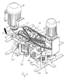
- Fig. 1 shows a perspective view of a strip cleaning device according to the first embodiment.
- the cleaning device is shown without an outer housing.
- the cleaning device for cleaning support strips of laser or flame cutting machines is preferably mounted on a frame 110, wherein impurities and / or deposits are to be removed in particular in the form of slag from the support strips.
- the cleaning device has a first and a second electric motor 10, 20, wherein the first electric motor 10 drives a toothed belt 11, while the second electric motor 20 drives a chain 21.
- the cleaning device has a first and a second conveyor unit 50, 60 for automatically conveying the strips to be cleaned by the cleaning device.
- a flail unit 30 is provided for knocking off the impurities or deposits on the support strips and a brush unit 40 for improved cleaning of those parts of the strip which have already been cleaned by the flail unit 30.
- the flail unit 30 and the brush unit 40 are driven by the toothed belt 11 and rotated.
- a diverter unit 90 may be provided for diverting the chain between the flail unit 30 and the brush unit 40.
- the first and second conveyor unit 40, 60 and the deflection unit 90 is driven by the chain 21.
- the first and second conveyor units 50, 60 have two conveyor rims on the left and right of the inserted bar to be cleaned in order to allow optimum conveyance of the bar by the cleaning device.
- the conveyor rings of the first conveyor unit 50 are each connected via a spring arm 75 with a prestressed spring 70, so that the conveyor rings can be pressed against the bar to be conveyed.
- a flail unit pair 30 and a brush unit pair 40 are provided (i.e., two flail units and two brush units) so that both sides of the bar to be cleaned can be cleaned simultaneously.
- the flail units of Schlegelüspaares, d. H. the left and right flail units are driven in opposite directions.
- the two brush units 40 which are spaced from each other, so that they can clean the two sides of a bar.
- the flail units and the brush units can be arranged offset from one another.
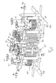
- FIG. 2 shows a further perspective view of the cleaning device according to FIG. 1.
- the first and second electric motors 10, 20 can be seen, which drive the toothed belt 11 and the chain 21.
- the first, second and third conveyor unit 50, 60, 90 and the flail unit 30 and the brush unit 40 are further shown.
- FIG. 3 shows a further perspective view of the cleaning device of FIG. 1 or 2.
- the illustration in FIG. 3 essentially corresponds to the illustration in FIG. 2, wherein the second electric motor and the chain 21 are no longer shown, so that further details the flail unit and the brush unit can be shown for illustration.
- the strips to be cleaned are inserted from the left into the cleaning device and conveyed through the first conveyor unit. Subsequently, the flail unit 30 serves to cut off impurities and / or deposits on the strip. Thereafter, the brush unit 40 is arranged to further clean the bar.
- the brushes of the brush unit can for example be made of metal, in particular steel.
- the second conveyor unit is provided, so that a bar can be easily promoted by the cleaning device.
- the two flail units 30 and the two brush units 40 are driven by the toothed belt 11. Since only one single toothed belt is used, the two flail units 30 and the two brush units 40 are driven in opposite directions to each other.
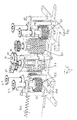
- Fig. 4 shows a further perspective view of the cleaning device of Fig. 1.
- the conveyor rings of the first conveyor unit and the second conveyor unit have gear wheels 51, 61.
- the deflection unit 90 has first and second gears 91, 92.
- the gears 51, 61, 91, 92 By means of the gears 51, 61, 91, 92, the first and second conveying unit 50, 60 and the deflection unit 90 are driven by the second electric motor 20 via the chain 21.
- the flail unit 30 and the brush unit 40 have toothed belt heads 31, 41 so that they can be driven by the first electric motor 10 and the toothed belt 11.
- the distance of the brush units 40 can be adjusted to the strip to be cleaned, for example, in a wear of the brushes.
- FIG. 5 shows another perspective view of the cleaning device according to FIG. 1 or 2.
- the front flail unit 30 and the front brush unit 40 are not shown.
- an end of a bar 100 is shown, which is conveyed through the two sprockets of the first conveyor unit 50 in the cleaning device.
- Fig. 6 shows another perspective view of the cleaning device according to Fig. 5. To further illustrate the operation of the cleaning device, the front conveyor rings of the conveyor units are not shown. The strip 100 is in this case further introduced into the cleaning device, so that the first end of the strip projects into the third conveyor unit.
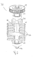
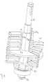
- Fig. 7 shows a perspective view of a flail unit.
- the flail unit 30 is held by two sheets 30a as shown in FIG.
- the flail unit has at its one end a head 31 which cooperates with the toothed belt 11 to set the flail unit 30 in rotation.
- the flail unit 30 also has a flail rod 37, a bearing plate 33 and a cover plate 39. Between the bearing plate 31 and the cover plate 39, a plurality of flails 35 and at least one guide plate 36 can be arranged.
- the guide plate 36 serves as a spacer for the flail unit.
- Fig. 8 shows a perspective view of the flail unit. To further illustrate the construction of the flail unit 30, the head 31 and the cover plates 39 are not shown. Thus, now the second flail rods 37a are shown, which receive the flails 35 and the spacers 38. Preferably, a spacer 38 is placed after a flail pair 35 on the second flail rod 37a.
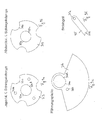
- FIGS. 9a to 9d respectively show plan views of elements of the flail unit.
- the bearing plate 33 for the first and second flails rods 37, 37a is shown.
- the flattened end 33d cooperates with the flattened end 37d of the first flail rod.
- the bearing plate further has another three holes 33b, so that the bearing plate 33 can be placed on both the first flail rod and on the three second flails rods.
- a cover plate for the first flail rod 37 is shown.
- the shape of the cover plate corresponds substantially to the shape of the conductor plate 33, wherein the cover plate, however, has no openings for receiving the second Schlegelstangen.
- Fig. 9c the embodiment of the guide plate 36 is shown.
- the guide plate is designed like a circle segment and has a first hole 36a with a flattened end 36d, which is designed such that the first flail rod 37 can be inserted with the flattened end 37a in the hole 36a.
- the guide plate also has a second hole 36b which can cooperate with the second flail rods 37a.
- Fig. 9d an embodiment of the bracket 35 is shown.
- the flail has a hole 35a which is configured such that a second flail rod can be inserted into the hole 35a.
- the mallet has a projection 35b.
- the elements of the flail unit are preferably made of steel and then cured accordingly.
- the screw 34 at the lower end of the flail unit the bearing plates 33, the cover plate 39, the guide plate 36 and the flails 35 can be replaced when worn.
- the flail units 30, the brush units 40, and the first and second conveyor units 50, 60 may be disassembled by loosening the corresponding threaded connections to be either repaired or replaced.
Landscapes
- Cleaning In General (AREA)
Applications Claiming Priority (1)
| Application Number | Priority Date | Filing Date | Title |
|---|---|---|---|
| DE102006055998A DE102006055998A1 (de) | 2006-11-24 | 2006-11-24 | Leistenreinigungsvorrichtung |
Publications (2)
| Publication Number | Publication Date |
|---|---|
| EP1925371A2 true EP1925371A2 (fr) | 2008-05-28 |
| EP1925371A3 EP1925371A3 (fr) | 2010-12-22 |
Family
ID=39092973
Family Applications (1)
| Application Number | Title | Priority Date | Filing Date |
|---|---|---|---|
| EP07121423A Withdrawn EP1925371A3 (fr) | 2006-11-24 | 2007-11-23 | Dispositif de nettoyage de tringles |
Country Status (2)
| Country | Link |
|---|---|
| EP (1) | EP1925371A3 (fr) |
| DE (1) | DE102006055998A1 (fr) |
Cited By (1)
| Publication number | Priority date | Publication date | Assignee | Title |
|---|---|---|---|---|
| CN119838917A (zh) * | 2025-03-19 | 2025-04-18 | 陕西凸鹏钛锆股份有限公司 | 一种钛带板面双向清洁装置 |
Family Cites Families (10)
| Publication number | Priority date | Publication date | Assignee | Title |
|---|---|---|---|---|
| DE1297060B (de) * | 1965-08-27 | 1969-06-04 | Joh Hinrich Lerbs Fa | Werkzeugkopf mit einer Vielzahl von Schlagwerkzeugen fuer Entrostungsvorrichtungen |
| DE6937646U (de) * | 1969-09-25 | 1970-01-02 | Wakue Vertrieb Walter Kuemmerl | Vorrichtung zur oberflaechenbearbeitung |
| DE8800781U1 (de) * | 1987-07-08 | 1988-03-10 | Festo KG, 7300 Esslingen | Werkzeug zum Entfernen von Material von einer Oberfläche durch Schlagen |
| DE3839220C2 (de) * | 1988-11-19 | 1998-07-02 | Festo Ag & Co | Rotationswerkzeug für eine Bearbeitungsmaschine zum Entfernen von Material, z. B. Rost, Farbe usw., von einer Oberfläche |
| DE4206823C2 (de) * | 1992-03-04 | 1994-04-21 | Helmuth Umbehr | Vorrichtung zur mechanischen Bearbeitung einer Oberfläche oder einer Vielzahl von schaftförmigen Gegenständen |
| DE19931209A1 (de) * | 1999-07-06 | 2001-01-11 | Helmut Piller | Verfahren und Vorrichtung zur Nassreinigung von Teppichbodenelementen |
| SE524143C2 (sv) * | 2002-11-11 | 2004-07-06 | Weland Ab | Anordning och förfarande för rensning av långsträckta bärorgan |
| FR2865154B1 (fr) * | 2004-01-19 | 2007-03-30 | Jean Paul Thuet | Dispositif de nettoyage d'un depot de matiere sur une barre. |
| DE202004015922U1 (de) * | 2004-10-13 | 2006-02-16 | Trumpf Grüsch AG | Maschinelle Vorrichtung zum Reinigen von Auflageleisten von Werkstückauflagen |
| DE102004060085A1 (de) * | 2004-12-14 | 2006-06-22 | Franz Hof Gmbh | Vorrichtung zum Reinigen von mit Schlacke behafteten Auflageleisten eines Werkstück-Auflagetisches |
-
2006
- 2006-11-24 DE DE102006055998A patent/DE102006055998A1/de not_active Withdrawn
-
2007
- 2007-11-23 EP EP07121423A patent/EP1925371A3/fr not_active Withdrawn
Cited By (1)
| Publication number | Priority date | Publication date | Assignee | Title |
|---|---|---|---|---|
| CN119838917A (zh) * | 2025-03-19 | 2025-04-18 | 陕西凸鹏钛锆股份有限公司 | 一种钛带板面双向清洁装置 |
Also Published As
| Publication number | Publication date |
|---|---|
| EP1925371A3 (fr) | 2010-12-22 |
| DE102006055998A1 (de) | 2008-05-29 |
Similar Documents
| Publication | Publication Date | Title |
|---|---|---|
| EP2338616B1 (fr) | Dispositif mécanique pour le nettoyage de barres d'appui de supports de pièces à usiner sur des machines-outils | |
| EP2012927B1 (fr) | Dispositif de desintegration | |
| DE3016804C2 (fr) | ||
| DE492674C (de) | Schraemkette | |
| DE3735302C2 (fr) | ||
| DE2707842C3 (de) | Raspelwerkzeug für eine Schäl- und Raspelvorrichtung zum Abtragen von Reifenlaufflächen | |
| DE102011084939B4 (de) | Vorrichtung zur Frakturierung von polykristallinem Silizium und Verfahren zur Herstellung frakturierter Fragmente von polykristallinem Silizium | |
| DE4037944C2 (de) | Handgerät für eine Gewindebearbeitung | |
| DE4443116C2 (de) | Einrichtung zum Reinigen von Spundwandbohlen | |
| EP1925371A2 (fr) | Dispositif de nettoyage de tringles | |
| DE1966005B2 (de) | Messerwelle für die Bearbeitung von Holz, Pappe, Kunststoff oder dgl | |
| EP0306719A1 (fr) | Dispositif racleur pour enlever la matière adhérant à un convoyeur à bande | |
| DE2801827A1 (de) | Vorrichtung an zerkleinerungsmaschinen, z.b. haeckslern | |
| DE10218778A1 (de) | Schaber für die Walzen einer Walzenmühle | |
| EP0260643B1 (fr) | Couteau pour un cultivateur de gazon | |
| DE202021101316U1 (de) | Bearbeitungseinheit für eine Blechbearbeitungsmaschine | |
| EP2009180B1 (fr) | Appareil de démoulage pour un rouleau compresseur | |
| DE4322225A1 (de) | Kombinierte Bohr- und Brennschneideinrichtung | |
| DE102005024166B4 (de) | Maschine und Fräsgruppe für die Bearbeitung von Tür- und Fensterteilen | |
| DE10253345B4 (de) | Vorrichtung zur Erleichterung der Hammermühlenwartung | |
| DE68913751T2 (de) | Schleifvorrichtung für die messer einer querschneidrolle. | |
| DE29707996U1 (de) | Kratzputzmaschine mit Gehäuse und Handgriff | |
| DE102023108270A1 (de) | Klingeneinheit und Reinigungsvorrichtung zum gleichzeitigen Entfernen von Schlacke von gegenüberliegenden Seiten einer Auflageleiste | |
| DE594782C (de) | Vorrichtung zum Zerschneiden eines Stranges mit Laengsvorschub | |
| DE2846238A1 (de) | Vorrichtung zum buersten von naturholzoberflaechen |
Legal Events
| Date | Code | Title | Description |
|---|---|---|---|
| PUAI | Public reference made under article 153(3) epc to a published international application that has entered the european phase |
Free format text: ORIGINAL CODE: 0009012 |
|
| AK | Designated contracting states |
Kind code of ref document: A2 Designated state(s): AT BE BG CH CY CZ DE DK EE ES FI FR GB GR HU IE IS IT LI LT LU LV MC MT NL PL PT RO SE SI SK TR |
|
| AX | Request for extension of the european patent |
Extension state: AL BA HR MK RS |
|
| PUAL | Search report despatched |
Free format text: ORIGINAL CODE: 0009013 |
|
| AK | Designated contracting states |
Kind code of ref document: A3 Designated state(s): AT BE BG CH CY CZ DE DK EE ES FI FR GB GR HU IE IS IT LI LT LU LV MC MT NL PL PT RO SE SI SK TR |
|
| AX | Request for extension of the european patent |
Extension state: AL BA HR MK RS |
|
| 17P | Request for examination filed |
Effective date: 20110622 |
|
| AKX | Designation fees paid |
Designated state(s): AT BE BG CH CY CZ DE DK EE ES FI FR GB GR HU IE IS IT LI LT LU LV MC MT NL PL PT RO SE SI SK TR |
|
| 17Q | First examination report despatched |
Effective date: 20110816 |
|
| GRAP | Despatch of communication of intention to grant a patent |
Free format text: ORIGINAL CODE: EPIDOSNIGR1 |
|
| STAA | Information on the status of an ep patent application or granted ep patent |
Free format text: STATUS: THE APPLICATION IS DEEMED TO BE WITHDRAWN |
|
| 18D | Application deemed to be withdrawn |
Effective date: 20130111 |