EP1924101A1 - Vorrichtung, verfahren und programm zur beurteilung von videokommunikationsqualität - Google Patents
Vorrichtung, verfahren und programm zur beurteilung von videokommunikationsqualität Download PDFInfo
- Publication number
- EP1924101A1 EP1924101A1 EP06797532A EP06797532A EP1924101A1 EP 1924101 A1 EP1924101 A1 EP 1924101A1 EP 06797532 A EP06797532 A EP 06797532A EP 06797532 A EP06797532 A EP 06797532A EP 1924101 A1 EP1924101 A1 EP 1924101A1
- Authority
- EP
- European Patent Office
- Prior art keywords
- delay
- video
- quality
- degradation amount
- quality degradation
- Prior art date
- Legal status (The legal status is an assumption and is not a legal conclusion. Google has not performed a legal analysis and makes no representation as to the accuracy of the status listed.)
- Granted
Links
- 238000004891 communication Methods 0.000 title claims abstract description 295
- 238000000034 method Methods 0.000 title claims description 20
- 230000015556 catabolic process Effects 0.000 claims abstract description 601
- 238000006731 degradation reaction Methods 0.000 claims abstract description 601
- 238000013441 quality evaluation Methods 0.000 claims abstract description 89
- 238000004364 calculation method Methods 0.000 claims description 110
- 230000007423 decrease Effects 0.000 claims description 25
- 238000012886 linear function Methods 0.000 claims description 19
- 239000002131 composite material Substances 0.000 claims description 8
- 238000012545 processing Methods 0.000 description 85
- 230000006870 function Effects 0.000 description 78
- 230000001934 delay Effects 0.000 description 15
- 230000014509 gene expression Effects 0.000 description 14
- 238000010586 diagram Methods 0.000 description 10
- 238000011156 evaluation Methods 0.000 description 10
- 230000008447 perception Effects 0.000 description 10
- 230000005540 biological transmission Effects 0.000 description 6
- 230000004044 response Effects 0.000 description 6
- 230000002093 peripheral effect Effects 0.000 description 5
- 230000002457 bidirectional effect Effects 0.000 description 4
- 230000000694 effects Effects 0.000 description 4
- 238000002474 experimental method Methods 0.000 description 4
- 230000003993 interaction Effects 0.000 description 4
- 238000005259 measurement Methods 0.000 description 3
- 238000010606 normalization Methods 0.000 description 3
- 230000001413 cellular effect Effects 0.000 description 2
- 230000006872 improvement Effects 0.000 description 2
- 238000012935 Averaging Methods 0.000 description 1
- 238000013528 artificial neural network Methods 0.000 description 1
- 230000008859 change Effects 0.000 description 1
- 238000007796 conventional method Methods 0.000 description 1
- 238000013461 design Methods 0.000 description 1
- 230000010365 information processing Effects 0.000 description 1
- 239000000203 mixture Substances 0.000 description 1
- 238000012360 testing method Methods 0.000 description 1
- 238000012546 transfer Methods 0.000 description 1
- 230000000007 visual effect Effects 0.000 description 1
Images


Classifications
-
- H—ELECTRICITY
- H04—ELECTRIC COMMUNICATION TECHNIQUE
- H04N—PICTORIAL COMMUNICATION, e.g. TELEVISION
- H04N17/00—Diagnosis, testing or measuring for television systems or their details
- H04N17/004—Diagnosis, testing or measuring for television systems or their details for digital television systems
-
- H—ELECTRICITY
- H04—ELECTRIC COMMUNICATION TECHNIQUE
- H04N—PICTORIAL COMMUNICATION, e.g. TELEVISION
- H04N17/00—Diagnosis, testing or measuring for television systems or their details
-
- H—ELECTRICITY
- H04—ELECTRIC COMMUNICATION TECHNIQUE
- H04N—PICTORIAL COMMUNICATION, e.g. TELEVISION
- H04N5/00—Details of television systems
- H04N5/04—Synchronising
Definitions
- the present invention relates to a communication quality estimation technique and, more particularly, to a technique of estimating quality associated with video communication of bidirectionally exchanging audio and video media upon compositing them.
- bidirectional multi-modal services based on the composition of audio and video media such as video communication services, e.g., video telephone/conference services, and collaboration services.
- the Internet used for such services is a network which does not always guarantee the communication quality. For this reason, in communicating audio and video media upon compositing them, if the operating band of a communication line connecting user terminals is narrow or congestion occurs in the network, the quality of user experience of audio information and video information which the user actually feels on the receiving terminal degrades.
- the occurrence of quality degradation in audio information is perceived as breaks, noise, and a response delay
- the occurrence of quality degradation in video information is perceived as phenomena such as defocus, blur, mosaic-shaped distortion, jerky effect, and a response delay.
- a user perceives a response delay caused by the synchronization between audio and video media, i.e., a video communication service response delay, the step-out between audio and video media which is caused by a response time delay offset, or the like due to the processing time taken for the transmission of audio and video media signals, a delay time in the network, and a delay time originating from the processing time taken for the reception of audio and video media signals.
- the processing time taken for the transmission of audio and video media signals includes the processing time taken to encode audio and video media, a transmission buffer time, and the like.
- Delay times in the network include the processing time taken by a router and the like constituting a network, the time based on the physical distance between the networks used by communicators, and the like.
- the processing time taken for the reception of audio and video media signals includes a reception buffer time, the decoding time for audio and video media, and the like.
- ITU-T recommendation P.862 International Telecommunication Union-Telecommunication Standardization Sector
- PESQ Perceptual Evaluation of Speech Quality
- video quality estimation technique an objective video quality evaluation scale is described in ITU-T recommendation J.144 and the like.
- VQEG Video Quality Experts Group
- step-out due to the absolute delay time from the input to the output of each medium and the relative delay time offset between media can be a factor that degrades the quality of the service.
- the above conventional techniques have a problem that no consideration is given to a quality estimation scale based on the comprehensive consideration of these quality factors.
- the degree of quality degradation due to step-out between media is greatly influenced by the frame rate of each frame obtained by encoding a video medium. In the prior art, however, since the frame rate is assumed to be constant at the standard value, i.e., 30 [frames/sec], if the frame rate differs from the standard value, the estimation accuracy of comprehensive quality degrades.
- the present invention has been made to solve this problem, and has as its object to provide a video communication quality estimation apparatus, method, and program which can estimate, with sufficient accuracy, quality associated with video communication of bidirectionally exchanging audio and video media upon compositing them.
- a program causes a computer of a video communication quality estimation apparatus which estimates quality associated with video communication of bidirectionally exchanging an audio medium and a video medium upon compositing the audio medium and the video medium between communication terminals connected via a network to execute a multi-modal quality estimation step of causing a multi-modal quality estimation unit to estimate a multi-modal quality value as a quality evaluation value of a composite medium obtained by compositing an audio medium output from a communication terminal and a video medium output from the communication terminal on the basis of an audio medium quality evaluation value as a quality evaluation value of the audio medium and a quality evaluation value of the video medium, an absolute delay quality degradation amount estimation step of causing a delay quality degradation amount estimation unit to estimate a delay quality degradation amount caused by an audio medium delay and a video medium delay on the basis of an audio delay time as a delay time from input of an audio medium to output of the audio medium between communication terminals and a video delay time as a delay time from input of a video medium to output of the video medium between the
- the multi-modal quality estimation unit estimates a multi-modal quality value on the basis of an audio quality evaluation value and a video quality evaluation value
- the delay quality degradation amount estimation unit estimates a delay quality degradation amount on the basis of an audio delay time and a video delay time.
- the video communication quality estimation unit estimates a video communication quality value on the basis of the multi-modal quality value and the delay quality degradation amount. This makes it possible to estimate a video communication quality value in consideration of quality degradation due to the delays of audio and video media, and hence to estimate, with sufficient accuracy, quality associated with video communication of bidirectionally exchanging audio and video media upon compositing them.
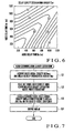
- FIG. 1 is a block diagram showing the arrangement of the video communication quality estimation apparatus according to the first embodiment of the present invention.
- a video communication quality estimation apparatus 1 comprises an information processing apparatus which performs arithmetic processing for input information and outputs the resultant information. This apparatus estimates quality associated with video communication of bidirectionally exchanging audio and video media upon compositing them between communication terminals connected via a network.
- the video communication quality estimation apparatus 1 includes a multi-modal quality estimation unit 11, delay quality degradation amount estimation unit 12, and video communication quality estimation unit 13 as main functional units.
- the multi-modal quality estimation unit 11 estimates a multi-modal quality value 23A as the quality evaluation value of a composite medium obtained by compositing audio and video media on the basis of an audio quality evaluation value 21A as the quality evaluation value of an audio medium output from a communication terminal and a video quality evaluation value 21B as the quality evaluation value of a video medium output from the communication terminal.
- the delay quality degradation amount estimation unit 12 estimates a delay quality degradation amount 23B originating from the delays of audio and video media on the basis of an audio delay time 22A as the delay time from the input to the output of an audio medium between communication terminals and a video delay time 22B as the delay time from the input to the output of a video medium between the communication terminals.
- the video communication quality estimation unit 13 estimates a video communication quality value 24 on the basis of the multi-modal quality value 23A estimated by the multi-modal quality estimation unit 11 and the delay quality degradation amount 23B estimated by the delay quality degradation amount estimation unit 12.
- the multi-modal quality estimation unit 11 has a function of estimating the multi-modal quality value 23A as the quality evaluation value of a composite medium obtained by compositing audio and video media on the basis of the audio quality evaluation value 21A as the quality evaluation value of an audio medium output from the communication terminal and the video quality evaluation value 21B as the quality evaluation value of a video medium output from the communication terminal.
- the multi-modal quality estimation unit 11 includes a storage unit 11A and a multi-modal quality calculation unit 11B as main functional means.
- the storage unit 11A stores, in advance, a multi-modal quality estimation model 31 representing the relationship between the audio quality evaluation value 21A, video quality evaluation value 21B, and multi-modal quality value 23A.
- the multi-modal quality calculation unit 11B has a function of calculating the multi-modal quality value 23A corresponding to the audio quality evaluation value 21A and video quality evaluation value 21B on the basis of the multi-modal quality estimation model 31 in the storage unit 11A.
- the audio quality evaluation value 21A is quality of user experience which the user actually feels against the audio medium which is transmitted from one communication terminal and is received and played back by the other communication terminal.
- the video quality evaluation value 21B is quality of user experience which the user actually feels against the video medium which is transmitted from one communication terminal and is received and played back by the other communication terminal.
- the delay quality degradation amount estimation unit 12 has a function of estimating the delay quality degradation amount 23B originating from the delays of audio and video media on the basis of the audio delay time 22A as the delay time from the input to the output of an audio medium between communication terminals and the video delay time 22B as the delay time from the input to the output of a video medium between the communication terminals.
- the delay quality degradation amount estimation unit 12 includes a storage unit 12A and delay quality degradation amount calculation unit 12B as main functional means.
- the storage unit 12A has a function of storing, in advance, a delay quality degradation amount estimation model 32 representing the relationship between the audio delay time 22A, video delay time 22B, and delay quality degradation amount 23B.
- the delay quality degradation amount calculation unit 12B has a function of calculating the delay quality degradation amount 23B corresponding to the audio delay time 22A and video delay time 22B on the basis of the delay quality degradation amount estimation model 32 in the storage unit 12A.
- the audio delay time 22A is the delay time from the input of an audio medium to one communication terminal to the output of the medium from the other communication terminal.
- the video delay time 22B is the delay time from the input of a video medium input to one communication terminal to the output of the medium from the other communication terminal.
- Specific delay times constituting the audio delay time 22A and the video delay time 22B include processing times at the times of transmission of audio and video media, delay times in the network, and processing times at the time of reception of the audio and video media.
- the processing times at the time of audio and video media signals include the processing times taken to encode audio and video media, a transmission buffer time, and the like.
- Delay times in the network include the processing time of a router and the like constituting the network, the time based on the physical distance between the networks used by communicators, and the like.
- the processing times taken at the time of reception of audio and video media include a reception buffer time, the decoding times taken for the audio and video media, and the like.
- the delay quality degradation amount estimation model 32 representing the relationship between the audio delay time 22A, video delay time 22B, and delay quality degradation amount 23B is derived by tests and stored in the storage unit 12A in advance, and the delay quality degradation amount estimation unit 12 calculates the delay quality degradation amount 23B corresponding to the newly calculated audio delay time 22A and video delay time 22B on the basis of the delay quality degradation amount estimation model 32 in the storage unit 12A.
- the video communication quality estimation unit 13 has a function of estimating the video communication quality value 24 implemented by a bidirectional multi-modal service in consideration of the multi-modal quality value 23A estimated by the multi-modal quality estimation unit 11 and the delay quality degradation amount 23B estimated by the delay quality degradation amount estimation unit 12.
- the video communication quality estimation unit 13 includes a storage unit 13A and video communication quality calculation unit 13B as main functional means.
- the storage unit 13A has a function of storing, in advance, the video communication quality estimation model 33 representing the relationship between the multi-modal quality value 23A, delay quality degradation amount 23B, and video communication quality value 24.
- the video communication quality calculation unit 13B has a function of calculating the video communication quality value 24 corresponding to the multi-modal quality value 23A and delay quality degradation amount 23B on the basis of the video communication quality estimation model 33 in the storage unit 13A.
- the storage unit for various types of arithmetic processing data and programs comprises storage devices such as a memory and a hard disk.
- An arithmetic processing unit (computer) for performing various types of arithmetic processing comprises a CPU and its peripheral circuits. This unit implements various types of functional means by reading and executing programs (not shown) in the storage unit so as to make the above hardware and programs operate cooperatively.
- the respective functional units can individually include storage units and arithmetic processing units or can share a storage unit and an arithmetic processing unit.
- Fig. 2 is a flowchart showing the overall processing operation of the video communication quality estimation apparatus according to the first embodiment of the present invention.
- audio quality evaluation value 21A, video quality evaluation value 21B, audio delay time 22A, and video delay time 22B have been input as pieces of quality information about an arbitrary video communication performed between communication terminals from an external apparatus, storage medium, communication network, or keyboard (not shown).
- a case in which a quality value concerning the video communication is estimated on the basis of these pieces of quality information will be described.
- the video communication quality estimation apparatus 1 starts the overall processing in Fig. 2 in response to the input of quality information or operator's operation representing the start of execution.
- the video communication quality estimation apparatus 1 causes the multi-modal quality estimation unit 11 to estimate the multi-modal quality value 23A corresponding to the audio quality evaluation value 21A and video quality evaluation value 21B by executing the multi-modal quality estimation step (step 100).
- the video communication quality estimation apparatus 1 causes the delay quality degradation amount estimation unit 12 to estimate the delay quality degradation amount 23B corresponding to the audio delay time 22A and video delay time 22B by executing the delay quality degradation amount estimation step (step 110).
- the video communication quality estimation apparatus 1 then causes the video communication quality estimation unit 13 to estimate the video communication quality value 24 corresponding to the multi-modal quality value 23A and delay quality degradation amount 23B by executing the video communication quality estimation step (step 120), and terminates the series of overall processing operations.
- multi-modal quality estimation step and the delay quality degradation amount estimation step can be executed concurrently or sequentially.
- Fig. 3 is a flowchart showing the multi-modal quality estimation processing by the video communication quality estimation apparatus according to the first embodiment of the present invention.
- the multi-modal quality estimation unit 11 of the video communication quality estimation apparatus 1 executes the multi-modal quality estimation processing in Fig. 3 in the multi-modal quality estimation step in step 100 in Fig. 2 .
- the multi-modal quality estimation unit 11 causes the multi-modal quality calculation unit 11B to acquire the externally input audio quality evaluation value 21A and video quality evaluation value 21B (step 101).
- the multi-modal quality calculation unit 11B reads out a model coefficient representing the multi-modal quality estimation model 31 from the storage unit 11A (step 102), and calculates the multi-modal quality value 23A corresponding to the audio quality evaluation value 21A and video quality evaluation value 21B on the basis of the multi-modal quality estimation model 31 (step 103).
- Fig. 4 shows an example of a characteristic of the multi-modal quality estimation model.
- the quality associated with video communication of bidirectionally exchanging audio and video media upon compositing them the quality without any consideration of quality degradation due to the delays of audio and video media will be referred to as the multi-modal quality value 23A.
- the multi-modal quality value 23A tends to monotonically increase with an increase in a video quality evaluation value MOSv when an audio quality evaluation value MOSa is constant, and to monotonically increase with an increase in the audio quality evaluation value MOSa when the video quality evaluation value MOSv is constant.
- the multi-modal quality value 23A can therefore be expressed by a mathematical expression representing the interaction between the audio quality evaluation value 21A and the video quality evaluation value 21B.
- MOSa be the audio quality evaluation value 21A
- MOSv be the video quality evaluation value 21B
- ⁇ 1, ⁇ 1, ⁇ 1, and ⁇ 1 be constants
- MOSmm be the multi-modal quality value 23A
- the multi-modal quality value 23A is normalized to be represented by a standard MOS (Mean Opinion Score) value taking a numerical value from 1 to 5.
- the multi-modal quality calculation unit 11B then outputs the calculated multi-modal quality value 23A to the video communication quality estimation unit 13 (step 104), and terminates the series of multi-modal quality estimation processing.
- Fig. 5 is a flowchart showing delay quality degradation amount estimation processing by the video communication quality estimation apparatus according to the first embodiment of the present invention.
- the delay quality degradation amount estimation unit 12 of the video communication quality estimation apparatus 1 executes the delay quality degradation amount estimation processing in Fig. 5 in the delay quality degradation amount estimation step in step 110 in Fig. 2 .
- the delay quality degradation amount estimation unit 12 acquires the externally input audio delay time 22A and video delay time 22B from the delay quality degradation amount calculation unit 12B (step 111).
- the delay quality degradation amount calculation unit 12B reads out a model coefficient representing the delay quality degradation amount estimation model 32 from the storage unit 12A (step 112), and calculates the delay quality degradation amount 23B corresponding to the audio delay time 22A and video delay time 22B on the basis of the delay quality degradation amount estimation model 32 (step 113).
- Fig. 6 shows an example of a characteristic of a delay quality degradation amount estimation model.
- a quality degradation amount due to the delays of the audio and video media will be referred to as the delay quality degradation amount 23B.
- a delay quality degradation amount Dav has a convex characteristic that it monotonically increases to reach a predetermined maximum value with an increase in a video delay time Dv, and monotonically decreases with a further increase in the video delay time Dv, when an audio delay time Da is constant.
- the delay quality degradation amount Dav has a convex characteristic that it monotonically increases to reach a predetermined maximum value with an increase in an audio delay time Da, and monotonically decreases with a further increase in the audio delay time Da, when the video delay time Dv is constant.
- the delay quality degradation amount 23B can therefore be expressed by a function expression with the audio delay time 22A and video delay time 22B as variables.
- Da be the audio delay time 22A
- Dv be the video delay time 22B
- f(Da, Dv) be a function expression representing the relationship between the audio delay time 22A, video delay time 22B, and delay quality degradation amount 23B
- min(a, b) be a function of selecting a smaller one of values a and b
- max(a, b) be a function of selecting a larger one of the values a and b
- Dav be the delay quality degradation amount 23B
- the delay quality degradation amount calculation unit 12B then outputs the calculated delay quality degradation amount 23B to the video communication quality estimation unit 13 (step 114), and terminates the series of delay quality degradation amount estimation processing.
- Fig. 7 is a flowchart showing video communication quality estimation processing by the video communication quality estimation apparatus, according to the first embodiment of the present invention.
- the video communication quality estimation unit 13 of the video communication quality estimation apparatus 1 executes the video communication quality estimation processing in Fig. 7 in the video communication quality estimation step in step 120 in Fig. 2 .
- the video communication quality estimation unit 13 causes the video communication quality calculation unit 13B to acquire the multi-modal quality value 23A estimated by the multi-modal quality estimation unit 11 and the delay quality degradation amount 23B estimated by the delay quality degradation amount estimation unit 12 (step 121).
- the video communication quality calculation unit 13B then reads out a model coefficient representing a video communication quality estimation model 33 from the storage unit 13A (step 122), and calculates the video communication quality value 24 corresponding to the multi-modal quality value 23A and delay quality degradation amount 23B on the basis of the video communication quality estimation model 33 (step 123).
- Fig. 8 shows an example of a characteristic of a video communication quality estimation model.
- the quality based on the consideration of a quality degradation amount due to the delays of the audio and video media will be referred to as the video communication quality value 24.
- a video communication quality value MOSall tends to monotonically increase with an increase in a delay quality degradation amount Dav when the multi-modal quality value MOSmm is constant, and to monotonically increase with an increase in a multi-modal quality value MOSmm when the delay quality degradation amount Dav is constant.
- the video communication quality value 24 can therefore be expressed by a mathematical expression representing the interaction between the multi-modal quality value 23A and the delay quality degradation amount 23B.
- MOSmm be the multi-modal quality value 23A
- Dav be the delay quality degradation amount 23B
- ⁇ 2, ⁇ 2, ⁇ 2, and ⁇ 2 be constants
- MOSall be the video communication quality value 24
- the video communication quality value 24 is normalized to be represented by a standard MOS value taking a numerical value from 1 to 5.
- the video communication quality calculation unit 13B then outputs the calculated video communication quality value 24 to a unit outside the apparatus, recording medium, communication network, storage unit, or display screen (not shown) (step 124), and terminates the series of video communication quality estimation processing.
- the multi-modal quality estimation unit 11 estimates the multi-modal quality value 23A on the basis of the audio quality evaluation value 21A and the video quality evaluation value 21B.
- the delay quality degradation amount estimation unit 12 estimates the delay quality degradation amount 23B on the basis of the audio delay time 22A and the video delay time 22B
- the video communication quality estimation unit 13 estimates the video communication quality value 24 on the basis of the multi-modal quality value 23A and the delay quality degradation amount 23B.
- the delay quality degradation amount estimation unit 12 also estimates the delay quality degradation amount 23B corresponding to the audio delay time 22A and video delay time 22B on the basis of the delay quality degradation amount estimation model 32 representing the relationship between the audio delay time, the video delay time, and the delay quality degradation amount. This makes it possible to accurately and easily estimate the delay quality degradation amount 23B.
- Fig. 9 is a graph showing estimation results on video communication quality estimation values obtained in this embodiment.
- the abscissa represents the video communication quality estimation values (MOS values) obtained in this embodiment; and the ordinate, the video communication quality actual measurement values (MOS values) as results on the respective video communications as estimation targets by actual opinion evaluation.
- the video communication quality estimation values obtained in this embodiment and the actual measurement values are plotted on the diagonal line on the graph.
- the determination coefficient is 0.91, which indicates that a high correlation is obtained.
- the average of the 95% confidence interval of the actual measurement values is 0.31, whereas the RMSE (Root Mean Square Error) of the estimated values is 0.16. This indicates that the estimated values have satisfactory estimation accuracy in a practical term.
- this embodiment uses the delay quality degradation amount estimation model 32, which has a convex characteristic that when the audio delay time Da is constant, the delay quality degradation amount Dav monotonically increases to reach a predetermined maximum value with an increase in a video delay time Dv, and monotonically decreases with a further increase in the video delay time Dv, and a convex characteristic that when the video delay time Dv is constant, the delay quality degradation amount Dav monotonically increases to reach a predetermined maximum value with an increase in an audio delay time Da, and monotonically decreases with a further increase in the audio delay time Da.
- This makes it possible to accurately and easily estimate a quality degradation amount corresponding to the human visual and auditory characteristics associated with quality degradation due to the delays of audio and video media.
- FIG. 10 is a block diagram showing the arrangement of the main part of the video communication quality estimation apparatus according to the second embodiment of the present invention.
- the same reference numerals as in Fig. 1 described above denote the same or similar parts in Fig. 10 .
- the delay quality degradation amount estimation unit 12 when estimating the delay quality degradation amount 23B corresponding to the audio delay time 22A and video delay time 22B, the delay quality degradation amount estimation unit 12 directly estimates the delay quality degradation amount 23B on the basis of the delay quality degradation amount estimation model 32 representing the relationship between an audio delay time, a video delay time, and a delay quality degradation amount.
- This embodiment exemplifies a case in which an absolute delay quality degradation amount representing quality degradation due to the absolute delays of audio and video media and a relative delay quality degradation amount representing a quality degradation due to the relative delays of the audio and video media are obtained from an audio delay time 22A and a video delay time 22B, and a delay quality degradation amount 23B is indirectly estimated from the absolute delay quality degradation amount and the relative degradation quality degradation amount.
- a video communication quality estimation apparatus 1 differs from that according to the first embodiment (see Fig. 1 ) only in a delay quality degradation amount estimation unit 12.
- Other arrangements are the same as those of the first embodiment, and a detailed description thereof will be omitted.
- the delay quality degradation amount estimation unit 12 includes a storage unit 12A, delay quality degradation amount calculation unit 12B, absolute delay quality degradation amount calculation unit 12C, and delay quality degradation amount calculation unit 12D as main functional means.
- the storage unit 12A has a function of storing, in advance, an absolute delay quality degradation amount estimation model 32A representing the relationship between the delay time sum of the audio delay time 22A and the video delay time 22B and an absolute delay quality degradation amount 26 and a relative delay quality degradation amount estimation model 32B representing the relationship between a relative delay quality degradation amount 27 and the delay time difference between the audio delay time 22A and the video delay time 22B.
- the absolute delay quality degradation amount calculation unit 12C has a function of calculating the absolute delay quality degradation amount 26 corresponding to the delay time sum of the audio delay time 22A and the video delay time 22B on the basis of the absolute delay quality degradation amount estimation model 32A in the storage unit 12A.
- the delay quality degradation amount calculation unit 12D has a function of calculating the relative delay quality degradation amount 27 corresponding to the delay time difference between the audio delay time 22A and the video delay time 22B on the basis of the relative delay quality degradation amount estimation model 32B in the storage unit 12A.
- the delay quality degradation amount calculation unit 12B has a function of calculating the delay quality degradation amount 23B corresponding to the audio delay time 22A and video delay time 22B on the basis of the absolute delay quality degradation amount 26 calculated by the absolute delay quality degradation amount calculation unit 12C and the relative delay quality degradation amount 27 calculated by the delay quality degradation amount calculation unit 12D.
- An absolute degradation quality degradation amount is a quality degradation amount originating from the absolute delays of audio and video media.
- a relative degradation quality degradation amount is a quality degradation amount originating from the relative delay difference between of the audio and video media.
- the absolute delay quality degradation amount 26 is defined as the absolute delay quality degradation amount 26.
- the absolute delay quality degradation amount calculation unit 12C estimates the absolute delay quality degradation amount 26 on the basis of the absolute delay quality degradation amount estimation model 32A representing a characteristic that the absolute delay quality degradation amount monotonically increases with an increase in the delay time sum of an audio delay time and a video delay time.
- the delay quality degradation amount calculation unit 12D estimates the relative delay quality degradation amount 27 on the basis of the relative delay quality degradation amount estimation model 32B representing a characteristic that a relative delay quality degradation amount monotonically increases with an increase in the delay time difference between an audio delay time and a video delay time.
- the storage unit for various types of arithmetic processing data and programs comprises storage devices such as a memory and a hard disk.
- An arithmetic processing unit (computer) for performing various types of arithmetic processing comprises a CPU and its peripheral circuits. This unit implements various types of functional means by reading and executing programs (not shown) in the storage unit so as to make the above hardware and programs operate cooperatively.
- the respective functional units can individually include storage units and arithmetic processing units or can share a storage unit and an arithmetic processing unit.
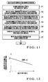
- Fig. 11 is a flowchart showing delay quality degradation amount estimation processing by the video communication quality estimation apparatus according to the second embodiment of the present invention.
- the operations of the video communication quality estimation apparatus 1 according to this embodiment differ from those according to the first embodiment in only delay quality degradation amount estimation operation.
- Other processing operations are the same as those of the first embodiment, and hence a detailed description thereof will be omitted.
- the delay quality degradation amount estimation unit 12 of the video communication quality estimation apparatus 1 executes the delay quality degradation amount estimation processing in Fig. 11 in the delay quality degradation amount estimation step in step 110 in Fig. 2 .
- the delay quality degradation amount estimation unit 12 acquires the externally input audio delay time 22A and video delay time 22B from the delay quality degradation amount calculation unit 12B (step 211).
- the delay quality degradation amount estimation unit 12 then causes the absolute delay quality degradation amount calculation unit 12C to read out a model coefficient representing the absolute delay quality degradation amount estimation model 32A from the storage unit 12A (step 212) and calculate the absolute delay quality degradation amount 26 corresponding to the delay time sum of the audio delay time 22A and the video delay time 22B on the basis of the absolute delay quality degradation amount estimation model 32A (step 213).
- Fig. 12 shows an example of a characteristic of absolute delay quality degradation amount estimation.
- the quality degradation component which changes in accordance with the delay time sum of the audio delay time 22A and the video delay time 22B will be referred to as the absolute delay quality degradation amount 26.
- the absolute delay quality degradation amount 26 tends to monotonically increase with an increase in a delay time sum Dr of an audio delay time Da and a video delay time Dv.
- the absolute delay quality degradation amount 26 can therefore be expressed by a linear function expression using the delay time sum of the audio delay time 22A and the video delay time 22B as a variable.
- Da be the audio delay time 22A
- Dv be the video delay time 22B
- Dr be a delay time sum
- the delay quality degradation amount estimation unit 12 causes the delay quality degradation amount calculation unit 12D to read out a model coefficient representing the relative delay quality degradation amount estimation model 32B from the storage unit 12A (step 214) and calculate the relative delay quality degradation amount 27 corresponding to the delay time difference between the audio delay time 22A and the video delay time 22B on the basis of the relative delay quality degradation amount estimation model 32B (step 215).
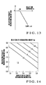
- Fig. 13 shows an example of a characteristic of relative delay quality degradation amount estimation.
- the quality degradation component which changes in accordance with the delay time difference between the audio delay time 22A and the video delay time 22B will be referred to as the relative delay quality degradation amount 27.
- the relative delay quality degradation amount 27 tends to indicate 0 until a delay time difference Ds between the audio delay time Da and the video delay time Dv reaches a predetermined value and monotonically decrease with a further increase in the delay time difference Ds.
- the relative delay quality degradation amount 27 can therefore be expressed by a linear function expression using the delay time difference between the audio delay time 22A and the video delay time 22B as a variable.
- Da the audio delay time 22A
- Dv the video delay time 22B
- Ds a delay time difference
- S(Dr) the relative delay quality degradation amount 27
- the delay quality degradation amount estimation unit 12 then causes the delay quality degradation amount calculation unit 12B to calculate the delay quality degradation amount 23B corresponding to the audio delay time 22A and video delay time 22B on the basis of the absolute delay quality degradation amount 26 calculated by the absolute delay quality degradation amount calculation unit 12C and the relative delay quality degradation amount 27 calculated by the delay quality degradation amount calculation unit 12D (step 216).
- Fig. 14 shows an example of a characteristic of delay quality degradation amount estimation. As shown in Fig. 14 , the delay quality degradation amount 23B tends to monotonically increase with an increase in the sum of an absolute delay quality degradation amount R(Dr) and a relative delay quality degradation amount S(Ds).
- the delay quality degradation amount 23B can therefore be expressed by, for example, the sum of the absolute delay quality degradation amount R(Dr) and the relative delay quality degradation amount S(Ds).
- R(Dr) be the absolute delay quality degradation amount 26
- Dav be the delay quality degradation amount 23B
- min(a, b) be a function of selecting a smaller one of values a and b
- max(a, b) be a function of selecting a larger one of the values a and b
- the delay quality degradation amount calculation unit 12B then outputs the calculated delay quality degradation amount 23B to a video communication quality estimation unit 13 (step 217), and terminates the series of delay quality degradation amount estimation processing.
- this embodiment obtains an absolute delay quality degradation amount representing quality degradation due to the absolute delays of audio and video media and a relative delay quality degradation amount representing quality degradation due to the relative delays of the audio and video media from the audio delay time 22A and the video delay time 22B, and indirectly estimates the delay quality degradation amount 23B from the absolute delay quality degradation amount and the relative degradation quality degradation amount.
- This makes it possible to estimate the delay quality degradation amount 23B corresponding to the audio delay time 22A and video delay time 22B with a very simple estimation model, and hence to reduce the processing load and processing time required for the estimation of video communication quality.
- the absolute delay quality degradation amount calculation unit 12C estimates an absolute delay quality degradation amount corresponding to the delay time sum of an audio delay time and a video delay time on the basis of an absolute delay quality degradation characteristic that the absolute delay quality degradation amount monotonically increases with an increase in the delay time sum of the audio delay time and the video delay time. This makes it possible to accurately estimate, with simple processing, an absolute delay quality degradation amount in consideration of the human perception characteristic of perceiving a degradation in video communication quality owing to the absolute delay from the input to the output of each medium.
- the delay quality degradation amount calculation unit 12D estimates an absolute delay quality degradation amount corresponding to the delay time difference between an audio delay time and video delay time on the basis of a relative delay quality degradation characteristic that the relative delay quality degradation amount monotonically decreases with an increase in the delay time difference between the audio delay time and the video delay time. This makes it possible to accurately estimate, with simple processing, a relative delay quality degradation amount in consideration of the human perception characteristic of perceiving a degradation in video communication quality owing to the relative delay time offset i.e., step-out, between media.
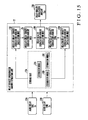
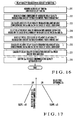
- FIG. 15 is a block diagram showing the arrangement of the main part of the video communication quality estimation apparatus according to the third embodiment of the present invention.
- the same reference numerals as in Fig. 10 described above denote the same or similar parts in Fig. 15 .
- the second embodiment has exemplified the case in which the relative delay quality degradation amount 27 corresponding to the delay time difference between the audio delay time 22A and the video delay time 22B is obtained on the basis of one relative delay quality degradation amount estimation model 32B.
- This embodiment exemplifies a case in which a relative delay quality degradation amount estimation model used for the estimation of a relative delay quality degradation amount 27 is selected on the basis of the relationship in magnitude between an audio delay time 22A and a video delay time 22B.
- the arrangement of a video communication quality estimation apparatus 1 according to this embodiment differs from that according to the second embodiment (see Fig. 10 ) only in a storage unit 12A and delay quality degradation amount calculation unit 12D of a delay quality degradation amount estimation unit 12.
- Other arrangements are the same as those of the second embodiment, and a detailed description thereof will be omitted.
- the delay quality degradation amount estimation unit 12 includes the storage unit 12A, a delay quality degradation amount calculation unit 12B, an absolute delay quality degradation amount calculation unit 12C, and the delay quality degradation amount calculation unit 12D as main functional means.
- the storage unit 12A has a function of storing, in advance, an absolute delay quality degradation amount estimation model 32A representing the relationship between the delay time sum of the audio delay time 22A and the video delay time 22B and an absolute delay quality degradation amount 26 and a plurality of different relative delay quality degradation amount estimation models 32B and 32C corresponding to the relationship in magnitude between the audio delay time 22A and the video delay time 22B.
- the absolute delay quality degradation amount calculation unit 12C has a function of calculating the absolute delay quality degradation amount 26 corresponding to the delay time sum of the audio delay time 22A and the video delay time 22B on the basis of the absolute delay quality degradation amount estimation model 32A in the storage unit 12A.
- the delay quality degradation amount calculation unit 12D has a function of selecting a relative delay quality degradation amount estimation model corresponding to the relationship in magnitude between the audio delay time 22A and the video delay time 22B from the storage unit 12A and a function of calculating the relative delay quality degradation amount 27 corresponding to the delay time difference between the audio delay time 22A and the video delay time 22B on the basis of the selected relative delay quality degradation amount estimation model.
- the delay quality degradation amount calculation unit 12B has a function of calculating the delay quality degradation amount 23B corresponding to the audio delay time 22A and video delay time 22B on the basis of the absolute delay quality degradation amount 26 calculated by the absolute delay quality degradation amount calculation unit 12C and the relative delay quality degradation amount 27 calculated by the delay quality degradation amount calculation unit 12D.
- the user perceives quality degradations of these media in accordance with the relative delay caused between the communication terminals, i.e., the step-out (playback timing offset) between the media.
- the user has a perception characteristic that the degree to which the user feels relative delay quality degradation changes in accordance with the relationship in magnitude between an audio delay time and a video delay time.
- This embodiment selects a relative delay quality degradation amount estimation model in accordance with the relationship in magnitude between an audio delay time and a video delay time, and causes the delay quality degradation amount calculation unit 12D to estimate the relative delay quality degradation amount 27 on the basis of the selected relative delay quality degradation amount estimation model.
- the storage unit for various types of arithmetic processing data and programs comprises storage devices such as a memory and a hard disk.
- An arithmetic processing unit (computer) for performing various types of arithmetic processing comprises a CPU and its peripheral circuits. This unit implements various types of functional means by reading and executing programs (not shown) in the storage unit so as to make the above hardware and programs operate cooperatively.
- the respective functional units can individually include storage units and arithmetic processing units or can share a storage unit and an arithmetic processing unit.
- Fig. 16 is a flowchart showing delay quality degradation amount estimation processing by the video communication quality estimation apparatus according to the third embodiment of the present invention.
- the operation of the video communication quality estimation apparatus 1 according to this embodiment differs from that according to the second embodiment only in delay quality degradation amount estimation operation.
- Other processing operations are the same as those of the second embodiment, and a detailed description thereof will be omitted.
- the delay quality degradation amount estimation unit 12 of the video communication quality estimation apparatus 1 executes the delay quality degradation amount processing in Fig. 16 in the delay quality degradation amount estimation step in step 110 in Fig. 2 .
- the delay quality degradation amount estimation unit 12 acquires the externally input audio delay time 22A and video delay time 22B from the delay quality degradation amount calculation unit 12B (step 311).
- the delay quality degradation amount estimation unit 12 reads out a model coefficient representing the absolute delay quality degradation amount estimation model 32A from the storage unit 12A (step 312), and calculates the absolute delay quality degradation amount 26 corresponding to the delay time sum of the audio delay time 22A and video delay time 22B on the basis of the absolute delay quality degradation amount estimation model 32A (step 313).
- Steps 311 to 313 are the same as steps 211 to 213 in Fig. 11 , and a detailed description thereof will be omitted.
- the delay quality degradation amount estimation unit 12 also causes the delay quality degradation amount calculation unit 12D to select a relative delay quality degradation amount estimation model corresponding to the relationship in magnitude between the audio delay time 22A and the video delay time 22B (step 314).
- the delay quality degradation amount estimation unit 12 then reads out a model coefficient representing the selected relative delay quality degradation amount estimation model from the storage unit 12A (step 315), and calculates the relative delay quality degradation amount 27 corresponding to the delay time difference between the audio delay time 22A and the video delay time 22B on the basis of this relative delay quality degradation amount estimation model (step 316).
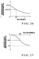
- Fig. 17 shows an example of a characteristic of relative delay quality degradation amount estimation.
- the storage unit 12A stores, in advance, as relative delay quality degradation characteristics perceived by a user, two relative delay quality degradation amount estimation models 32B and 32C corresponding to the relationship in magnitude between the audio delay time 22A and the video delay time 22B, which is information indicating whether the audio delay time 22A is longer or shorter than the video delay time 22B in this case, i.e., the sign of a delay time difference Ds.
- the relative delay quality degradation amount estimation model 32B is used when the audio delay time 22A is equal to or more than the video delay time 22B
- the relative delay quality degradation amount estimation model 32C is used when the audio delay time 22A is shorter than the video delay time 22B.
- the relative delay quality degradation amount 27 tends to indicate 0 until the delay time difference Ds between an audio delay time Da and a video delay time Dv reaches a predetermined value and monotonically decrease with a further increase in the delay time difference Ds.
- the relative delay quality degradation amount 27 tends to indicate 0 until the delay time difference Ds between the audio delay time Da and the video delay time Dv reaches a predetermined value and monotonically decrease with a decrease in the delay time difference Ds.
- the relative delay quality degradation amount 27 can be expressed by a linear function expression using the delay time difference between the audio delay time 22A and the video delay time 22B as a variable.
- ⁇ 5 and ⁇ 5 be constants
- S(Ds) be the relative delay quality degradation amount 27
- the relative delay quality degradation amount 27 can be expressed by a linear function expression using the delay time difference between the audio delay time 22A and the video delay time 22B as a variable.
- ⁇ 6 and ⁇ 6 be constants
- S(Ds) be the relative delay quality degradation amount 27
- the delay quality degradation amount estimation unit 12 then causes the delay quality degradation amount calculation unit 12B to calculate a delay quality degradation amount 23B corresponding to the audio delay time 22A and video delay time 22B on the basis of the absolute delay quality degradation amount 26 calculated by the absolute delay quality degradation amount calculation unit 12C and the relative delay quality degradation amount 27 calculated by the delay quality degradation amount calculation unit 12D (step 317).
- Step 317 is the same as step 216 in Fig. 11 , and a detailed description thereof will be omitted.
- the delay quality degradation amount calculation unit 12B then outputs the calculated delay quality degradation amount 23B to the video communication quality estimation unit 13 (step 319), and terminates the series of delay quality degradation amount estimation processing.
- the storage unit 12A stores, in advance, the plurality of relative delay quality degradation amount estimation models 32B and 32C corresponding to the relationship in magnitude between the audio delay time 22A and the video delay time 22B, and the delay quality degradation amount calculation unit 12D selects a relative delay quality degradation amount estimation model corresponding to the relationship in magnitude between the audio delay time 22A and the video delay time 22B and calculates the relative delay quality degradation amount 27 corresponding to the delay time difference between the audio delay time 22A and the video delay time 22B on the basis of the selected relative delay quality degradation amount estimation model.
- This makes it possible to accurately estimate, with simple processing, a relative delay quality degradation amount in consideration of the human perception characteristic that the degree to which the user feels relative delay quality degradation changes in accordance with the relationship in magnitude between an audio delay time and a video delay time.
- a user feels video communication quality degradation more when an audio medium is played back with a delay from a video medium than when an audio medium is played back preceding a video medium.
- Using this embodiment therefore, makes it possible to estimate a relative delay quality degradation amount in consideration of such a perception characteristic and hence to estimate video communication quality with high accuracy.
- FIG. 18 is a block diagram showing the arrangement of the main part of the video communication quality estimation apparatus according to the fourth embodiment of the present invention.
- the same reference numerals as in Fig. 10 described above denote the same or similar parts in Fig. 18 .
- the second embodiment has exemplified the case in which the relative delay quality degradation amount 27 corresponding to the audio delay time 22A and video delay time 22B is obtained on the basis of the relative delay quality degradation amount estimation model 32B.
- This embodiment exemplifies a case in which a frame rate 22C is used in addition to an audio delay time 22A and a video delay time 22B, and a relative delay quality degradation amount 27 corresponding to the audio delay time 22A, video delay time 22B, and frame rate 22C is obtained.
- a frame rate is the transfer rate of frames constituting a video medium, and is expressed by the number of frames to be transmitted per unit time.
- the arrangement of a video communication quality estimation apparatus 1 according to this embodiment differs from that according to the second embodiment (see Fig. 10 ) only in a storage unit 12A and delay quality degradation amount calculation unit 12D of a delay quality degradation amount estimation unit 12.
- a slope coefficient calculation unit 12E is newly added to the arrangement of this embodiment.
- Other embodiments are the same as those of the second embodiment, and a detailed description thereof will be omitted.
- the delay quality degradation amount estimation unit 12 includes the storage unit 12A, a delay quality degradation amount calculation unit 12B, an absolute delay quality degradation amount calculation unit 12C, the delay quality degradation amount calculation unit 12D, and the slope coefficient calculation unit 12E as main functional means.
- the storage unit 12A has a function of storing, in advance, an absolute delay quality degradation amount estimation model 32A representing the relationship between the delay time sum of the audio delay time 22A and the video delay time 22B and an absolute delay quality degradation amount 26, a relative delay quality degradation amount estimation model 32B representing the relationship between the delay time difference between the audio delay time 22A and the video delay time 22B and the relative delay quality degradation amount 27, and a slope coefficient estimation model 32D representing the relationship between the frame rate 22C and a slope coefficient representing the slope of the relative delay quality degradation amount estimation model 32B.
- an absolute delay quality degradation amount estimation model 32A representing the relationship between the delay time sum of the audio delay time 22A and the video delay time 22B and an absolute delay quality degradation amount 26
- a relative delay quality degradation amount estimation model 32B representing the relationship between the delay time difference between the audio delay time 22A and the video delay time 22B and the relative delay quality degradation amount
- a slope coefficient estimation model 32D representing the relationship between the frame rate 22C and a slope coefficient representing the slope of the relative delay quality degradation amount estimation
- the absolute delay quality degradation amount calculation unit 12C has a function of calculating the absolute delay quality degradation amount 26 corresponding to the delay time sum of the audio delay time 22A and the video delay time 22B on the basis of the absolute delay quality degradation amount estimation model 32A in the storage unit 12A.
- the slope coefficient calculation unit 12E has a function of calculating a slope coefficient indicating the slope of the relative delay quality degradation amount estimation model 32B on the basis of the slope coefficient estimation model 32D in the storage unit 12A.
- the delay quality degradation amount calculation unit 12D has a function of specifying the slope of the relative delay quality degradation amount estimation model 32B in the storage unit 12A on the basis of the slope coefficient calculated by the slope coefficient calculation unit 12E, and a function of calculating the relative delay quality degradation amount 27 corresponding to the delay time difference between the audio delay time 22A and the video delay time 22B on the basis of the delay quality degradation amount estimation model 32 whose slope is specified.
- the delay quality degradation amount calculation unit 12B has a function of calculating a delay quality degradation amount 23B corresponding to the audio delay time 22A and video delay time 22B on the basis of the absolute delay quality degradation amount 26 calculated by the absolute delay quality degradation amount calculation unit 12C and the relative delay quality degradation amount 27 calculated by the delay quality degradation amount calculation unit 12D.
- the degree of a relative delay quality degradation amount is influenced by the frame rate of a video medium. If, for example, the frame rate is low, even a relative offset between audio and video media is not perceived as a large quality degradation. As the frame rate increases, however, the quality degradation becomes more noticeable. There are many systems which cannot achieve a frame rate of 30 [frames/sec] like a recent system which provides videophone services using cellular phones. It is therefore a very important challenge to obtain comprehensive multi-modal quality in consideration of even changes in frame rate.
- the delay quality degradation amount calculation unit 12D uses, as a linear function, the relative delay quality degradation amount estimation model 32B, and the slope coefficient calculation unit 12E calculates the slope coefficient of a linear function corresponding to a frame rate on the basis of a characteristic that the slope coefficient of this linear function increases in a logarithmic function manner with an increase in frame rate, i.e., the slope coefficient estimation model 32D. This makes it possible to estimate the relative delay quality degradation amount of the video communication in consideration of even changes in frame rate.
- the storage unit for various types of arithmetic processing data and programs comprises storage devices such as a memory and a hard disk.
- An arithmetic processing unit (computer) for performing various types of arithmetic processing comprises a CPU and its peripheral circuits. This unit implements various types of functional means by reading and executing programs (not shown) in the storage unit so as to make the above hardware and programs operate cooperatively.
- the respective functional units can individually include storage units and arithmetic processing units or can share a storage unit and an arithmetic processing unit.
- Fig. 19 is a flowchart showing delay quality degradation amount estimation processing by the video communication quality estimation apparatus according to the fourth embodiment of the present invention.
- the operation of the video communication quality estimation apparatus 1 according to this embodiment differs from that according to the second embodiment only in delay quality degradation amount estimation operation.
- Other processing operations are the same as those of the second embodiment, and a detailed description thereof will be omitted.
- the delay quality degradation amount estimation unit 12 of the video communication quality estimation apparatus 1 executes the delay quality degradation amount estimation processing in Fig. 19 in the delay quality degradation amount estimation step in step 110 in Fig. 2 .
- the delay quality degradation amount estimation unit 12 causes the delay quality degradation amount calculation unit 12B to acquire the externally input audio delay time 22A, video delay time 22B, and frame rate 22C (step 411).
- the delay quality degradation amount estimation unit 12 then causes the absolute delay quality degradation amount calculation unit 12C to read out a model coefficient representing the absolute delay quality degradation amount estimation model 32A from the storage unit 12A (step 412) and calculate the absolute delay quality degradation amount 26 corresponding to the delay time sum of the audio delay time 22A and the video delay time 22B on the basis of the absolute delay quality degradation amount estimation model 32A (step 413).
- Steps 411 to 413 are the same as steps 211 to 213 in Fig. 11 described above, and a detailed description thereof will be omitted.
- the delay quality degradation amount estimation unit 12 also causes the slope coefficient calculation unit 12E to read out a model coefficient representing the slope coefficient estimation model 32D from the storage unit 12A (step 414) and calculate a slope coefficient indicating the slope of the relative delay quality degradation amount estimation model 32B on the basis of the slope coefficient estimation model 32D (step 415).
- Fig. 20 shows an example of a characteristic of relative delay quality degradation amount estimation.
- the relative delay quality degradation amount 27 tends to indicate 0 until a delay time difference Ds between an audio delay time Da and a video delay time Dv reaches a predetermined value and monotonically decrease with a further increase in the delay time difference Ds.
- a slope ⁇ 4 of the relative delay quality degradation amount estimation model 32B tends to become gentle with a decrease in the frame rate 22C.
- Fig. 21 shows an example of a characteristic of slope coefficient estimation. As shown in Fig. 21 , the slope ⁇ 4 of the relative delay quality degradation amount estimation model 32B tends to monotonically decrease with an increase in the logarithmic value of the frame rate 22C.
- the slope coefficient ⁇ 4 can therefore be expressed by a linear function expression using the logarithmic value of the frame rate 22C as a variable.
- F be the frame rate 22C
- log(F) be the logarithmic value of the frame rate
- ⁇ 41 and ⁇ 41 be constants
- ⁇ 4 be the slope coefficient of the relative delay quality degradation amount estimation model 32B
- the delay quality degradation amount estimation unit 12 then causes the delay quality degradation amount calculation unit 12D to read out a model coefficient representing the relative delay quality degradation amount estimation model 32B from the storage unit 12A (step 416) and specify the slope of the relative delay quality degradation amount estimation model 32B by letting the model coefficient contain the slope coefficient calculated by the slope coefficient calculation unit 12E (step 417).
- the delay quality degradation amount estimation unit 12 calculates the relative delay quality degradation amount 27 corresponding to the delay time difference between the audio delay time 22A and the video delay time 22B on the basis of the obtained relative delay quality degradation amount estimation model 32B (step 418).
- the delay quality degradation amount estimation unit 12 causes the delay quality degradation amount calculation unit 12B to calculate the delay quality degradation amount 23B corresponding to the audio delay time 22A and video delay time 22B on the basis of the absolute delay quality degradation amount 26 calculated by the absolute delay quality degradation amount calculation unit 12C and the relative delay quality degradation amount 27 calculated by the delay quality degradation amount calculation unit 12D (step 419).
- Steps 418 and 419 are the same as steps 215 and 216 in Fig. 11 described above, and a detailed description thereof will be omitted.
- the delay quality degradation amount calculation unit 12B then outputs the calculated delay quality degradation amount 23B to the video communication quality estimation unit 13 (step 420), and terminates the series of delay quality degradation amount estimation processing.
- this embodiment uses the relative delay quality degradation amount estimation model 32B as a linear function and causes the slope coefficient calculation unit 12E to estimate the slope coefficient of a linear function corresponding to a frame rate on the basis of a slope coefficient estimation model in which the slope coefficient of the linear function increases in a logarithmic function manner with an increase in frame rate.
- the embodiment then calculates the relative delay quality degradation amount 27 corresponding to the delay time difference between the audio delay time 22A and the video delay time 22B on the basis of the relative delay quality degradation amount estimation model 32B specified by this slope coefficient. This makes it possible to accurately estimate, with simple processing, a relative delay quality degradation amount in consideration of the human perception characteristic that the degree to which the user feels relative delay quality degradation in accordance with the frame rate of a video medium.
- FIG. 22 is a block diagram showing the arrangement of the main part of the video communication quality estimation apparatus according to the fifth embodiment of the present invention.
- the same reference numerals as in Fig. 18 described above denote the same or similar parts in Fig. 22 .
- the fourth embodiment has exemplified the case in which the slope of one relative delay quality degradation amount estimation model 32B based on a linear function is specified by the slope coefficient calculated by the frame rate 22C, and the relative delay quality degradation amount 27 corresponding to the delay time difference between the audio delay time 22A and the video delay time 22B is obtained on the basis of the specified relative delay quality degradation amount estimation model 32B.
- This embodiment exemplifies a case in which a relative delay quality degradation amount estimation model used for the estimation of a relative delay quality degradation amount 27 is selected on the basis of the relationship in magnitude between an audio delay time 22A and a video delay time 22B.
- the arrangement of the video communication quality estimation apparatus 1 according to this embodiment differs from that according to the second embodiment (see Fig. 10 ) only in a storage unit 12A and delay quality degradation amount calculation unit 12D of a delay quality degradation amount estimation unit 12.
- Other arrangements are the same as those of the fourth embodiment, and a detailed description thereof will be omitted.
- the delay quality degradation amount estimation unit 12 includes the storage unit 12A, a delay quality degradation amount calculation unit 12B, an absolute delay quality degradation amount calculation unit 12C, the delay quality degradation amount calculation unit 12D, and a slope coefficient calculation unit 12E as main functional means.
- the storage unit 12A has a function of storing, in advance, an absolute delay quality degradation amount estimation model 32A representing the relationship between the delay time sum of the audio delay time 22A and the video delay time 22B and an absolute delay quality degradation amount 26, a plurality of different relative delay quality degradation amount estimation models 32B and 32C corresponding to the relationship in magnitude between the audio delay time 22A and the video delay time 22B, and a plurality of different slope coefficient estimation models 32D and 32E corresponding to the relationship in magnitude between the audio delay time 22A and the video delay time 22B.
- an absolute delay quality degradation amount estimation model 32A representing the relationship between the delay time sum of the audio delay time 22A and the video delay time 22B and an absolute delay quality degradation amount 26
- a plurality of different relative delay quality degradation amount estimation models 32B and 32C corresponding to the relationship in magnitude between the audio delay time 22A and the video delay time 22B
- a plurality of different slope coefficient estimation models 32D and 32E corresponding to the relationship in magnitude between the audio delay time 22A and the video delay time 22
- the absolute delay quality degradation amount calculation unit 12C has a function of calculating the absolute delay quality degradation amount 26 corresponding to the delay time sum of the audio delay time 22A and the video delay time 22B on the basis of the absolute delay quality degradation amount estimation model 32A in the storage unit 12A.
- the slope coefficient calculation unit 12E has a function of selecting a slope coefficient estimation model corresponding to the relationship in magnitude between the audio delay time 22A and the video delay time 22B from the storage unit 12A and a function of calculating a slope coefficient indicating the slope of the relative delay quality degradation amount estimation model 32B on the basis of the selected slope coefficient estimation model 32D.
- the delay quality degradation amount calculation unit 12D has a function of selecting a relative delay quality degradation amount estimation model corresponding to the relationship in magnitude between the audio delay time 22A and the video delay time 22B and a function of calculating the relative delay quality degradation amount 27 corresponding to the delay time difference between the audio delay time 22A and the video delay time 22B on the basis of the selected relative delay quality,degradation amount estimation model.
- the delay quality degradation amount calculation unit 12B has a function of calculating the delay quality degradation amount 23B corresponding to the audio delay time 22A and video delay time 22B on the basis of the absolute delay quality degradation amount 26 calculated by the absolute delay quality degradation amount calculation unit 12C and the relative delay quality degradation amount 27 calculated by the delay quality degradation amount calculation unit 12D.
- the user perceives quality degradations of these media in accordance with the relative delay caused between the communication terminals, i.e., the step-out (playback timing offset) between the media.
- the user has a perception characteristic that the degree to which he/she feels relative delay quality degradation changes in accordance with the relationship in magnitude between an audio delay time and a video delay time.
- This embodiment selects a slope coefficient estimation model and relative delay quality degradation amount estimation model in accordance with the relationship in magnitude between an audio delay time and a video delay time, and causes the slope coefficient calculation unit 12E to calculate a slope coefficient corresponding to the frame rate of a video medium on the basis of the selected slope coefficient estimation model.
- the embodiment specifies the slope of the selected relative delay quality degradation amount estimation model from the slope coefficient, and causes the delay quality degradation amount calculation unit 12D to estimate the relative delay quality degradation amount 27 on the basis of the relative delay quality degradation amount estimation model.
- the storage unit for various types of arithmetic processing data and programs comprises storage devices such as a memory and a hard disk.
- An arithmetic processing unit (computer) for performing various types of arithmetic processing comprises a CPU and its peripheral circuits. This unit implements various types of functional means by reading and executing programs (not shown) in the storage unit so as to make the above hardware and programs operate cooperatively.
- the respective functional units can individually include storage units and arithmetic processing units or can share a storage unit and an arithmetic processing unit.
- Fig. 23 is a flowchart showing delay quality degradation amount estimation processing by the video communication quality estimation apparatus according to the fifth embodiment of the present invention.
- the operations of a video communication quality estimation apparatus 1 according to this embodiment differ from those according to the fourth embodiment in only delay quality degradation amount estimation operation.
- Other processing operations are the same as those of the fourth embodiment, and a detailed description thereof will be omitted.
- the delay quality degradation amount estimation unit 12 of the video communication quality estimation apparatus 1 executes the delay quality degradation amount estimation processing in Fig. 23 in the delay quality degradation amount estimation step in step 110 in Fig. 2 .
- the delay quality degradation amount estimation unit 12 causes the delay quality degradation amount calculation unit 12B to acquire the audio delay time 22A, the video delay time 22B, and a frame rate 22C which are externally input (step S511).
- the delay quality degradation amount estimation unit 12 then causes the absolute delay quality degradation amount calculation unit 12C to read out a model coefficient representing the absolute delay quality degradation amount estimation model 32A from the storage unit 12A (step 512) and calculate the absolute delay quality degradation amount 26 corresponding to the delay time sum of the audio delay time 22A and the video delay time 22B on the basis of the absolute delay quality degradation amount estimation model 32A (step 513).
- Steps 511 to 513 are the same as steps 211 to 213 in Fig. 11 , and a detailed description thereof will be omitted.
- the delay quality degradation amount estimation unit 12 also causes the slope coefficient calculation unit 12E to select a slope coefficient estimation model corresponding to the relationship in magnitude between the audio delay time 22A and the video delay time 22B (step 514).
- the delay quality degradation amount estimation unit 12 then reads out a model coefficient representing the slope coefficient estimation model 32D from the storage unit 1,2A (step 515), and calculates a slope coefficient indicating the slope of the relative delay quality degradation amount estimation model 32B on the basis of the slope coefficient estimation model 32D (step 516).
- Fig. 24 shows an example of a characteristic of relative delay quality degradation amount estimation.
- the storage unit 12A stores, in advance, as relative delay quality degradation characteristics perceived by a user, two relative delay quality degradation amount estimation models 32B and 32C corresponding to the relationship in magnitude between the audio delay time 22A and the video delay time 22B, which is information indicating whether the audio delay time 22A is longer or shorter than the video delay time 22B in this case, i.e., the sign of a delay time difference Ds.
- the relative delay quality degradation amount estimation model 32B is used when the audio delay time 22A is equal to or more than the video delay time 22B
- the relative delay quality degradation amount estimation model 32C is used when the audio delay time 22A is shorter than the video delay time 22B.
- the relative delay quality degradation amount 27 tends to indicate 0 until the delay time difference Ds between an audio delay time Da and a video delay time Dv reaches a predetermined value and monotonically decrease with a further increase in the delay time difference Ds.
- the relative delay quality degradation amount 27 tends to indicate 0 until the delay time difference Ds between the audio delay time Da and the video delay time Dv reaches a predetermined value and monotonically decrease with a further decrease in the delay time difference Ds.
- the slopes ⁇ 5 and ⁇ 6 of the relative delay quality degradation amount estimation models 32B and 32C tend to become moderate with a decrease in the frame rate 22C.
- Fig. 25 shows an example of a characteristic of slope coefficient estimation.
- the slope ⁇ 5 of the relative delay quality degradation amount estimation model 32B tends to monotonically decrease with an increase in the logarithmic value of the frame rate 22C.
- the slope ⁇ 6 of the relative delay quality degradation amount estimation model 32C tends to monotonically increase with an increase in the logarithmic value of the frame rate 22C.
- the slope coefficients ⁇ 5 and ⁇ 6 can therefore be expressed by a linear function expression using the logarithmic value of the frame rate 22C as a variable.
- F be the frame rate 22C
- log(F) be the logarithmic value of the frame rate
- ⁇ 51 and ⁇ 51 be constants
- ⁇ 5 be the slope coefficient of the relative delay quality degradation amount estimation model 32B
- the delay quality degradation amount estimation unit 12 then causes the delay quality degradation amount calculation unit 12D to read out a relative delay quality degradation amount estimation model corresponding to the relationship in magnitude between the audio delay time 22A and the video delay time 22B (step 517).
- the delay quality degradation amount estimation unit 12 then reads out a model coefficient representing the selected relative delay quality degradation amount estimation model from the storage unit 12A (step 518) and specifies the slope of the relative delay quality degradation amount estimation model by letting the model coefficient contain the slope coefficient ⁇ 5 or ⁇ 6 calculated by the slope coefficient calculation unit 12E (step 519).
- the delay quality degradation amount estimation unit 12 calculates the relative delay quality degradation amount 27 corresponding to the delay time difference between the audio delay time 22A and the video delay time 22B on the basis of the obtained relative delay quality degradation amount estimation model (step 520).
- the delay quality degradation amount estimation unit 12 causes the delay quality degradation amount calculation unit 12B to calculate the delay quality degradation amount 23B corresponding to the audio delay time 22A and video delay time 22B on the basis of the absolute delay quality degradation amount 26 calculated by the absolute delay quality degradation amount calculation unit 12C and the relative delay quality degradation amount 27 calculated by the delay quality degradation amount calculation unit 12D (step 521).
- Steps 517 and 518 are the same as steps 314 and 315 in Fig. 16 described above
- step 519 is the same as step 417 in Fig. 19 described above
- steps 520 and 521 are the same as steps 215 and 216 in Fig. 11 described above. A detailed description of these steps will be omitted.
- the delay quality degradation amount calculation unit 12B then outputs the calculated delay quality degradation amount 23B to the video communication quality estimation unit 13 (step 522), and terminates the series of delay quality degradation amount estimation processing.
- this embodiment selects a slope coefficient estimation model and a relative delay quality degradation amount estimation model in accordance with the relationship in magnitude between an audio delay time and a video delay time, and causes the slope coefficient calculation unit 12E to calculate a slope coefficient corresponding to the frame rate of a video medium on the basis of the selected slope coefficient estimation model.
- the embodiment specifies the slope of the selected relative delay quality degradation amount estimation model in accordance with the slope coefficient, and causes the delay quality degradation amount calculation unit 12D to estimate the relative delay quality degradation amount 27 on the basis of this relative delay quality degradation amount estimation model.
- FIG. 26 shows an example of a characteristic of an absolute delay quality degradation amount estimation model used by the video communication quality estimation apparatus according to the sixth embodiment of the present invention.
- the second embodiment has exemplified the case in which when the absolute delay quality degradation amount calculation unit 12C of the delay quality degradation amount estimation unit 12 calculates the absolute delay quality degradation amount 26 corresponding to the delay time sum of the audio delay time 22A and the video delay time 22B, the absolute delay quality degradation amount estimation model 32A is modeled with a linear function.
- This embodiment exemplifies a case in which an absolute delay quality degradation amount estimation model 32A is modeled with a nonlinear function. Note that other arrangements and operations are the same as those of the second embodiment, and a detailed description thereof will be omitted.
- the absolute delay quality degradation amount estimation model 32A varies to some extent depending on an environment in which a video communication as an evaluation target is performed. In some cases, therefore, modeling the absolute delay quality degradation amount estimation model 32A with a nonlinear function rather than a linear function leads to an improvement in estimation accuracy.
- this embodiment models the absolute delay quality degradation amount estimation model 32A with a nonlinear function, and hence can improve the estimation accuracy.
- Using an exponential function makes it possible to model the absolute delay quality degradation amount estimation model 32A with a simple function expression.
- this embodiment can be applied to the third to fifth embodiments as well as the second embodiment, and similar functions and effects can be obtained.
- a plurality of relative delay quality degradation amount estimation models are used for the estimation of the relative delay quality degradation amount 27 on the basis of the relationship in magnitude between the audio delay time 22A and the video delay time 22B, and these relative delay quality degradation amount estimation models can be modeled with nonlinear functions.
- FIG. 27 shows an example of a characteristic of a relative delay quality degradation amount estimation model used by the video communication quality estimation apparatus according to the seventh embodiment of the present invention.
- the second embodiment has exemplified the case in which when calculating the relative delay quality degradation amount 27 corresponding to the delay time difference between the audio delay time 22A and the video delay time 22B, the relative delay quality degradation amount calculation unit 12D of the delay quality degradation amount estimation unit 12 models the relative delay quality degradation amount estimation model 32B with a linear function.
- This embodiment exemplifies a case in which the relative delay quality degradation amount estimation model 32B is modeled with a nonlinear function. Other arrangements and operations are the same as those of the second embodiment, and a detailed description thereof will be omitted.
- a relative delay quality degradation amount estimation model 32B varies to some extent depending on an environment in which a video communication as an evaluation target is performed. In some cases, therefore, modeling an absolute delay quality degradation amount estimation model 32A with a nonlinear function rather than a linear function leads to an improvement in estimation accuracy.
- this embodiment models the relative delay quality degradation amount estimation model 32B with a nonlinear function, and hence can improve the estimation accuracy.
- Using a logistic function makes it possible to model the relative delay quality degradation amount estimation model 32B with a simple function expression. Note that this embodiment can be applied to the third to fifth embodiments as well as the second embodiment, and similar functions and effects can be obtained.
- the relative delay quality degradation amount estimation model 32B When the relative delay quality degradation amount estimation model 32B is to be modeled with a nonlinear function, as in the same manner indicated by equations (11) and (12) described in the third embodiment, it suffices to store, in the storage unit 12A in advance, the two relative delay quality degradation amount estimation models 32B corresponding to the relationship in magnitude between an audio delay time 22A and a video delay time 22B and select the relative delay quality degradation amount estimation model 32B used for the estimation of the relative delay quality degradation amount 27 on the basis of the relationship in magnitude between the audio delay time 22A and the video delay time 22B.
- Fig. 28 shows another example of a characteristic of relative delay quality degradation amount estimation.
- a relative delay quality degradation amount 27 tends to gradually decrease from 0 until the delay time difference Ds between the audio delay time Da and the video delay time Dv reaches a predetermined value and monotonically decrease with a further increase in the delay time difference Ds.
- the relative delay quality degradation amount 27 tends to gradually decrease from 0 until the delay time difference Ds between the audio delay time Da and the video delay time Dv reaches a predetermined value and monotonically decrease with a further decrease in the delay time difference Ds.
- the relative delay quality degradation amount 27 can be expressed by a logistic function expression using the delay time difference between the audio delay time 22A and the video delay time 22B as a variable.
- ⁇ 9, ⁇ 9, and Ds9 be constants
- S(Ds) be the relative delay quality degradation amount 27
- the relative delay quality degradation amount 27 can be expressed by a logistic function expression using the delay time difference between the audio delay time 22A and the video delay time 22B as a variable.
- ⁇ 10, ⁇ 10, and Ds10 be constants
- S(Ds) be the relative delay quality degradation amount 27
- Figs. 27 and 28 each show the tendency that the relative delay quality degradation amount 27 converges to coefficients ⁇ 8 to ⁇ 10 at an end portion of the example of a characteristic.
- the delay quality degradation amount 23B is normalized to the MOS value range of 1 to 5 as indicated by equation (10) given above, the portion corresponding to the above tendency at the end portion of the example of a characteristic is not used for the actual estimation of the relative delay quality degradation amount 27.
- a function other than equations (17) to (19) using logistic functions may be used.
- Fig. 29 shows another example of a characteristic of relative delay quality degradation amount estimation. With regard to such an example of a characteristic, equations (17) to (19) can be expressed by exponential functions.
- a communication environment including communication terminals and an encoding scheme, which uses video communication, and the like to be used and an assumed usage scene such as a business meeting or a free conversation are set, and an evaluation experimental system which can control video quality including audio quality and a video frame rate and audio and video delay times is constructed.
- video quality including audio quality and a video frame rate and audio and video delay times is constructed.
- network emulator apparatus which can control network quality parameters such as a packet loss rate, and a packet delay time/fluctuation time.
- the video frame rate can be changed by a set parameter in a video communication application.
- Video communication is then performed between communication terminals in accordance with the above assumed scene while audio quality, video quality including a video frame rate, and audio and video delay times are changed in various states, and video communication quality is evaluated by a five-grade quality scale in comprehensive consideration of all quality factors.
- a quality is expressed by a MOS (Mean Opinion Score) value.
- a MOS value is obtained by assigning scores of 5 to 1 to "excellent”, “good”, “fair”, “poor”, and “bad” of the five-grade quality scale, respectively, and averaging the scores voted by persons who evaluate.
- an audio quality evaluation value and a video quality evaluation value are obtained in addition to a video communication quality in the same manner as described above. Note that the details of a subjective evaluation experiment method is described in ITU-T recommendation P.911.
- values derived by using an objective quality estimation technique such as ITU-T recommendation P.862 or ITU-T recommendation J.144 described above can be used.
- constants ⁇ 1, ⁇ 1, ⁇ 1, and ⁇ 1 are derived by approximating the relationship between the audio quality evaluation value MOSa, the video quality evaluation value MOSv, and the multi-modal quality value MOSmm with the function form of equation (1) on the basis of evaluation results obtained under a condition free from the influence of time delays.
- Constants ⁇ 3, ⁇ 3, ⁇ 5, ⁇ 51, ⁇ 52, ⁇ 6, ⁇ 61, and ⁇ 62 are then derived by approximating quality degradation amounts obtained when the audio and video delay times are changed under the condition in which audio quality and video quality are at the maximum levels with the function forms of equations (6) to (8), (11), (12), (14), and (15), respectively.
- each embodiment has been described on the premise that there is symmetry between an audio quality evaluation value and a video quality evaluation value in each communication terminal which performs video communication by using a multi-modal service, and the two communication terminals obtain equal audio quality evaluation values and equal video quality evaluation values. If there is no symmetry between an audio quality evaluation value and a video quality evaluation value, and the two communication terminals cannot obtain equal audio quality evaluation values and equal video quality evaluation values, for example, the multi-modal quality estimation unit 11 can calculate the multi-modal quality value 23A obtained by combining multi-modal qualities in the two communication terminals.
- the multi-modal quality estimation unit 11 can estimate the individual multi-modal quality value 23A for each communication terminal, and the video communication quality estimation unit 13 can estimate the video communication quality value 24 on the basis of the multi-modal quality value 23A and the delay quality degradation amount 23B.
- the second to fifth embodiments have exemplified the case in which when calculating the delay quality degradation amount Dav corresponding to the audio delay time 22A and video delay time 22B, the delay quality degradation amount calculation unit 12B calculates Dav from the sum of the absolute delay quality degradation amount R(Dr) calculated by the absolute delay quality degradation amount calculation unit 12C and the relative delay quality degradation amount S(Ds) calculated by the delay quality degradation amount calculation unit 12D.
- the present invention is not limited to this.
- Dav can be estimated from equation (23) given below and can be estimated in consideration of the interaction between R(Dr) and S (Ds) .
- Dav ⁇ ⁇ 14 ⁇ R Dr + ⁇ ⁇ 14 ⁇ S Ds + ⁇ ⁇ 14 ⁇ R Dr ⁇ S Ds + ⁇ ⁇ 14
- each embodiment has exemplified the case in which one or two estimation models are used as estimation models for calculating various types of quality values and slope coefficients.
- the present invention is not limited to this.
- Parameters that influence a video communication environment include, for example, a communication type parameter indicating the communication type of a video communication service, a playback performance parameter indicating the playback performance of a terminal which plays back a video medium, and a playback environment parameter indicating the playback environment of a terminal which plays back a video medium.
- a communication type parameter there is "task" indicating the type of communication performed in a video communication service as an evaluation target.
- playback performance parameters include not only "encoding scheme”, “video format”, and “key frame” associated with encoding of a video medium but also “monitor size”, “monitor resolution”, and the like associated with a medium playback function in a terminal.
- playback environment parameters include "indoor illuminance" at the time of playback of a medium in a terminal.
- Each embodiment has exemplified the case in which a calculated quality value represented by a MOS value is normalized to fall within the MOS value range of 1 to 5. If, however, calculated quality values fall within the range of 1 to 5, the normalization processing can be omitted.
- each embodiment has exemplified the case in which functions such as min() and max() are used as specific examples of normalization.
- normalization can be performed by using other functions.
- each embodiment has exemplified the case in which estimation models are modeled with linear and nonlinear functions.
- these estimation models are not limited to functions, and models other than functions can be used.
- a database in a table form in which the input/output relationship of an estimation model is defined.
- a black box model whose input/output characteristic is specified alone, e.g., a neural network or a case base.
Applications Claiming Priority (3)
| Application Number | Priority Date | Filing Date | Title |
|---|---|---|---|
| JP2005257880 | 2005-09-06 | ||
| JP2006171240 | 2006-06-21 | ||
| PCT/JP2006/317637 WO2007029731A1 (ja) | 2005-09-06 | 2006-09-06 | 映像コミュニケーション品質推定装置、方法、およびプログラム |
Publications (3)
| Publication Number | Publication Date |
|---|---|
| EP1924101A1 true EP1924101A1 (de) | 2008-05-21 |
| EP1924101A4 EP1924101A4 (de) | 2011-09-14 |
| EP1924101B1 EP1924101B1 (de) | 2013-04-03 |
Family
ID=37835850
Family Applications (1)
| Application Number | Title | Priority Date | Filing Date |
|---|---|---|---|
| EP06797532A Active EP1924101B1 (de) | 2005-09-06 | 2006-09-06 | Vorrichtung, verfahren und programm zur beurteilung von videokommunikationsqualität |
Country Status (7)
| Country | Link |
|---|---|
| US (1) | US8405773B2 (de) |
| EP (1) | EP1924101B1 (de) |
| JP (1) | JP4486130B2 (de) |
| KR (1) | KR100947275B1 (de) |
| CN (1) | CN101248679B (de) |
| CA (1) | CA2617893C (de) |
| WO (1) | WO2007029731A1 (de) |
Cited By (4)
| Publication number | Priority date | Publication date | Assignee | Title |
|---|---|---|---|---|
| EP2288087A1 (de) * | 2008-06-11 | 2011-02-23 | Nippon Telegraph and Telephone Corporation | Verfahren zur schätzung der audioqualität; vorrichtung zur schätzung der audioqualität und programm |
| EP2592829A1 (de) * | 2010-07-05 | 2013-05-15 | Mitsubishi Electric Corporation | Bildqualitäts-managementsystem |
| EP2327213B1 (de) * | 2008-08-21 | 2014-10-08 | Dolby Laboratories Licensing Corporation | Merkmalsbasierte berechnung von audio video synchronisierungsfehlern |
| EP2852159A4 (de) * | 2012-08-22 | 2015-07-08 | Huawei Tech Co Ltd | Verfahren und vorrichtung für multimedia-qualitätskontrolle |
Families Citing this family (151)
| Publication number | Priority date | Publication date | Assignee | Title |
|---|---|---|---|---|
| US8875217B2 (en) * | 2006-11-06 | 2014-10-28 | Panasonic Corporation | Receiver |
| US8554868B2 (en) | 2007-01-05 | 2013-10-08 | Yahoo! Inc. | Simultaneous sharing communication interface |
| US8599704B2 (en) * | 2007-01-23 | 2013-12-03 | Microsoft Corporation | Assessing gateway quality using audio systems |
| JP4802183B2 (ja) * | 2007-12-28 | 2011-10-26 | 日本電信電話株式会社 | マルチメディア総合品質推定方法および装置 |
| EP2106154A1 (de) * | 2008-03-28 | 2009-09-30 | Deutsche Telekom AG | Audiovisuelle Qualitätsbewertung |
| US8284259B2 (en) * | 2009-09-23 | 2012-10-09 | Avaya Inc. | Policy-based video quality assessment |
| KR101345098B1 (ko) * | 2009-12-18 | 2013-12-26 | 한국전자통신연구원 | 실시간 영상품질 측정 장치 및 방법 |
| JP5373704B2 (ja) * | 2010-06-16 | 2013-12-18 | 日本電信電話株式会社 | マルチメディア品質推定装置およびマルチメディア品質推定方法 |
| EP2732383B1 (de) | 2011-07-12 | 2018-04-04 | Snap Inc. | Verfahren und systeme zur bereitstellung von funktionen zur bearbeitung visueller inhalte |
| US11734712B2 (en) | 2012-02-24 | 2023-08-22 | Foursquare Labs, Inc. | Attributing in-store visits to media consumption based on data collected from user devices |
| US8972357B2 (en) | 2012-02-24 | 2015-03-03 | Placed, Inc. | System and method for data collection to validate location data |
| US10155168B2 (en) | 2012-05-08 | 2018-12-18 | Snap Inc. | System and method for adaptable avatars |
| WO2014031899A1 (en) | 2012-08-22 | 2014-02-27 | Goldrun Corporation | Augmented reality virtual content platform apparatuses, methods and systems |
| US8775972B2 (en) | 2012-11-08 | 2014-07-08 | Snapchat, Inc. | Apparatus and method for single action control of social network profile access |
| JP6127476B2 (ja) * | 2012-11-30 | 2017-05-17 | ヤマハ株式会社 | ネットワーク音楽セッションにおける遅延測定方法及び装置 |
| US10439972B1 (en) | 2013-05-30 | 2019-10-08 | Snap Inc. | Apparatus and method for maintaining a message thread with opt-in permanence for entries |
| US9705831B2 (en) | 2013-05-30 | 2017-07-11 | Snap Inc. | Apparatus and method for maintaining a message thread with opt-in permanence for entries |
| US9742713B2 (en) | 2013-05-30 | 2017-08-22 | Snap Inc. | Apparatus and method for maintaining a message thread with opt-in permanence for entries |
| US9083770B1 (en) | 2013-11-26 | 2015-07-14 | Snapchat, Inc. | Method and system for integrating real time communication features in applications |
| CA2863124A1 (en) | 2014-01-03 | 2015-07-03 | Investel Capital Corporation | User content sharing system and method with automated external content integration |
| US9628950B1 (en) | 2014-01-12 | 2017-04-18 | Investment Asset Holdings Llc | Location-based messaging |
| US10082926B1 (en) * | 2014-02-21 | 2018-09-25 | Snap Inc. | Apparatus and method for alternate channel communication initiated through a common message thread |
| US8909725B1 (en) | 2014-03-07 | 2014-12-09 | Snapchat, Inc. | Content delivery network for ephemeral objects |
| US9276886B1 (en) | 2014-05-09 | 2016-03-01 | Snapchat, Inc. | Apparatus and method for dynamically configuring application component tiles |
| US9396354B1 (en) | 2014-05-28 | 2016-07-19 | Snapchat, Inc. | Apparatus and method for automated privacy protection in distributed images |
| US9537811B2 (en) | 2014-10-02 | 2017-01-03 | Snap Inc. | Ephemeral gallery of ephemeral messages |
| IL239237B (en) | 2014-06-05 | 2018-12-31 | Rotem Efrat | Network document extension |
| US9113301B1 (en) | 2014-06-13 | 2015-08-18 | Snapchat, Inc. | Geo-location based event gallery |
| US9225897B1 (en) | 2014-07-07 | 2015-12-29 | Snapchat, Inc. | Apparatus and method for supplying content aware photo filters |
| US10055717B1 (en) | 2014-08-22 | 2018-08-21 | Snap Inc. | Message processor with application prompts |
| US10423983B2 (en) | 2014-09-16 | 2019-09-24 | Snap Inc. | Determining targeting information based on a predictive targeting model |
| US10824654B2 (en) | 2014-09-18 | 2020-11-03 | Snap Inc. | Geolocation-based pictographs |
| US11216869B2 (en) | 2014-09-23 | 2022-01-04 | Snap Inc. | User interface to augment an image using geolocation |
| US10284508B1 (en) | 2014-10-02 | 2019-05-07 | Snap Inc. | Ephemeral gallery of ephemeral messages with opt-in permanence |
| KR101600284B1 (ko) * | 2014-10-17 | 2016-03-07 | 주식회사 이노와이어리스 | 영상 품질 측정 방법 |
| US9015285B1 (en) | 2014-11-12 | 2015-04-21 | Snapchat, Inc. | User interface for accessing media at a geographic location |
| US10311916B2 (en) | 2014-12-19 | 2019-06-04 | Snap Inc. | Gallery of videos set to an audio time line |
| US9854219B2 (en) | 2014-12-19 | 2017-12-26 | Snap Inc. | Gallery of videos set to an audio time line |
| US9385983B1 (en) | 2014-12-19 | 2016-07-05 | Snapchat, Inc. | Gallery of messages from individuals with a shared interest |
| US9754355B2 (en) | 2015-01-09 | 2017-09-05 | Snap Inc. | Object recognition based photo filters |
| US11388226B1 (en) | 2015-01-13 | 2022-07-12 | Snap Inc. | Guided personal identity based actions |
| US10133705B1 (en) | 2015-01-19 | 2018-11-20 | Snap Inc. | Multichannel system |
| US9521515B2 (en) | 2015-01-26 | 2016-12-13 | Mobli Technologies 2010 Ltd. | Content request by location |
| US10223397B1 (en) | 2015-03-13 | 2019-03-05 | Snap Inc. | Social graph based co-location of network users |
| KR102217723B1 (ko) | 2015-03-18 | 2021-02-19 | 스냅 인코포레이티드 | 지오-펜스 인가 프로비저닝 |
| US9692967B1 (en) | 2015-03-23 | 2017-06-27 | Snap Inc. | Systems and methods for reducing boot time and power consumption in camera systems |
| US9881094B2 (en) | 2015-05-05 | 2018-01-30 | Snap Inc. | Systems and methods for automated local story generation and curation |
| US10135949B1 (en) | 2015-05-05 | 2018-11-20 | Snap Inc. | Systems and methods for story and sub-story navigation |
| US10993069B2 (en) | 2015-07-16 | 2021-04-27 | Snap Inc. | Dynamically adaptive media content delivery |
| US10817898B2 (en) | 2015-08-13 | 2020-10-27 | Placed, Llc | Determining exposures to content presented by physical objects |
| US9652896B1 (en) | 2015-10-30 | 2017-05-16 | Snap Inc. | Image based tracking in augmented reality systems |
| US9984499B1 (en) | 2015-11-30 | 2018-05-29 | Snap Inc. | Image and point cloud based tracking and in augmented reality systems |
| US10474321B2 (en) | 2015-11-30 | 2019-11-12 | Snap Inc. | Network resource location linking and visual content sharing |
| US10869072B2 (en) * | 2015-12-16 | 2020-12-15 | Nippon Telegraph And Telephone Corporation | Audio-visual quality estimation device, method for estimating audio-visual quality, and program |
| US10354425B2 (en) | 2015-12-18 | 2019-07-16 | Snap Inc. | Method and system for providing context relevant media augmentation |
| US10285001B2 (en) | 2016-02-26 | 2019-05-07 | Snap Inc. | Generation, curation, and presentation of media collections |
| US11023514B2 (en) | 2016-02-26 | 2021-06-01 | Snap Inc. | Methods and systems for generation, curation, and presentation of media collections |
| US10679389B2 (en) | 2016-02-26 | 2020-06-09 | Snap Inc. | Methods and systems for generation, curation, and presentation of media collections |
| US10339365B2 (en) | 2016-03-31 | 2019-07-02 | Snap Inc. | Automated avatar generation |
| US11900418B2 (en) | 2016-04-04 | 2024-02-13 | Snap Inc. | Mutable geo-fencing system |
| US11201981B1 (en) | 2016-06-20 | 2021-12-14 | Pipbin, Inc. | System for notification of user accessibility of curated location-dependent content in an augmented estate |
| US11785161B1 (en) | 2016-06-20 | 2023-10-10 | Pipbin, Inc. | System for user accessibility of tagged curated augmented reality content |
| US10334134B1 (en) | 2016-06-20 | 2019-06-25 | Maximillian John Suiter | Augmented real estate with location and chattel tagging system and apparatus for virtual diary, scrapbooking, game play, messaging, canvasing, advertising and social interaction |
| US11876941B1 (en) | 2016-06-20 | 2024-01-16 | Pipbin, Inc. | Clickable augmented reality content manager, system, and network |
| US11044393B1 (en) | 2016-06-20 | 2021-06-22 | Pipbin, Inc. | System for curation and display of location-dependent augmented reality content in an augmented estate system |
| US10805696B1 (en) | 2016-06-20 | 2020-10-13 | Pipbin, Inc. | System for recording and targeting tagged content of user interest |
| US10638256B1 (en) | 2016-06-20 | 2020-04-28 | Pipbin, Inc. | System for distribution and display of mobile targeted augmented reality content |
| US9681265B1 (en) | 2016-06-28 | 2017-06-13 | Snap Inc. | System to track engagement of media items |
| US10430838B1 (en) | 2016-06-28 | 2019-10-01 | Snap Inc. | Methods and systems for generation, curation, and presentation of media collections with automated advertising |
| US10733255B1 (en) | 2016-06-30 | 2020-08-04 | Snap Inc. | Systems and methods for content navigation with automated curation |
| US10348662B2 (en) | 2016-07-19 | 2019-07-09 | Snap Inc. | Generating customized electronic messaging graphics |
| CN109804411B (zh) | 2016-08-30 | 2023-02-17 | 斯纳普公司 | 用于同时定位和映射的系统和方法 |
| US10432559B2 (en) | 2016-10-24 | 2019-10-01 | Snap Inc. | Generating and displaying customized avatars in electronic messages |
| EP3535756B1 (de) | 2016-11-07 | 2021-07-28 | Snap Inc. | Selektive identifizierung und reihenfolge von bildmodifikatoren |
| US10203855B2 (en) | 2016-12-09 | 2019-02-12 | Snap Inc. | Customized user-controlled media overlays |
| US11616745B2 (en) | 2017-01-09 | 2023-03-28 | Snap Inc. | Contextual generation and selection of customized media content |
| US10454857B1 (en) | 2017-01-23 | 2019-10-22 | Snap Inc. | Customized digital avatar accessories |
| US10915911B2 (en) | 2017-02-03 | 2021-02-09 | Snap Inc. | System to determine a price-schedule to distribute media content |
| US10319149B1 (en) | 2017-02-17 | 2019-06-11 | Snap Inc. | Augmented reality anamorphosis system |
| US11250075B1 (en) | 2017-02-17 | 2022-02-15 | Snap Inc. | Searching social media content |
| US10074381B1 (en) | 2017-02-20 | 2018-09-11 | Snap Inc. | Augmented reality speech balloon system |
| US10565795B2 (en) | 2017-03-06 | 2020-02-18 | Snap Inc. | Virtual vision system |
| US10523625B1 (en) | 2017-03-09 | 2019-12-31 | Snap Inc. | Restricted group content collection |
| US10581782B2 (en) | 2017-03-27 | 2020-03-03 | Snap Inc. | Generating a stitched data stream |
| US10582277B2 (en) | 2017-03-27 | 2020-03-03 | Snap Inc. | Generating a stitched data stream |
| US11170393B1 (en) | 2017-04-11 | 2021-11-09 | Snap Inc. | System to calculate an engagement score of location based media content |
| US10387730B1 (en) | 2017-04-20 | 2019-08-20 | Snap Inc. | Augmented reality typography personalization system |
| US11893647B2 (en) | 2017-04-27 | 2024-02-06 | Snap Inc. | Location-based virtual avatars |
| CN110945555A (zh) | 2017-04-27 | 2020-03-31 | 斯纳普公司 | 社交媒体平台上用户位置的区域级别表示 |
| US10212541B1 (en) | 2017-04-27 | 2019-02-19 | Snap Inc. | Selective location-based identity communication |
| US10467147B1 (en) | 2017-04-28 | 2019-11-05 | Snap Inc. | Precaching unlockable data elements |
| US10803120B1 (en) | 2017-05-31 | 2020-10-13 | Snap Inc. | Geolocation based playlists |
| US11475254B1 (en) | 2017-09-08 | 2022-10-18 | Snap Inc. | Multimodal entity identification |
| US10740974B1 (en) | 2017-09-15 | 2020-08-11 | Snap Inc. | Augmented reality system |
| US10499191B1 (en) | 2017-10-09 | 2019-12-03 | Snap Inc. | Context sensitive presentation of content |
| US10573043B2 (en) | 2017-10-30 | 2020-02-25 | Snap Inc. | Mobile-based cartographic control of display content |
| US11265273B1 (en) | 2017-12-01 | 2022-03-01 | Snap, Inc. | Dynamic media overlay with smart widget |
| US11017173B1 (en) | 2017-12-22 | 2021-05-25 | Snap Inc. | Named entity recognition visual context and caption data |
| US10678818B2 (en) | 2018-01-03 | 2020-06-09 | Snap Inc. | Tag distribution visualization system |
| US11507614B1 (en) | 2018-02-13 | 2022-11-22 | Snap Inc. | Icon based tagging |
| US10979752B1 (en) | 2018-02-28 | 2021-04-13 | Snap Inc. | Generating media content items based on location information |
| US10885136B1 (en) | 2018-02-28 | 2021-01-05 | Snap Inc. | Audience filtering system |
| US10327096B1 (en) | 2018-03-06 | 2019-06-18 | Snap Inc. | Geo-fence selection system |
| KR102574151B1 (ko) | 2018-03-14 | 2023-09-06 | 스냅 인코포레이티드 | 위치 정보에 기초한 수집가능한 항목들의 생성 |
| US11163941B1 (en) | 2018-03-30 | 2021-11-02 | Snap Inc. | Annotating a collection of media content items |
| US10219111B1 (en) | 2018-04-18 | 2019-02-26 | Snap Inc. | Visitation tracking system |
| US10896197B1 (en) | 2018-05-22 | 2021-01-19 | Snap Inc. | Event detection system |
| US10679393B2 (en) | 2018-07-24 | 2020-06-09 | Snap Inc. | Conditional modification of augmented reality object |
| US10997760B2 (en) | 2018-08-31 | 2021-05-04 | Snap Inc. | Augmented reality anthropomorphization system |
| US10698583B2 (en) | 2018-09-28 | 2020-06-30 | Snap Inc. | Collaborative achievement interface |
| US10778623B1 (en) | 2018-10-31 | 2020-09-15 | Snap Inc. | Messaging and gaming applications communication platform |
| US10939236B1 (en) | 2018-11-30 | 2021-03-02 | Snap Inc. | Position service to determine relative position to map features |
| US11199957B1 (en) | 2018-11-30 | 2021-12-14 | Snap Inc. | Generating customized avatars based on location information |
| US11032670B1 (en) | 2019-01-14 | 2021-06-08 | Snap Inc. | Destination sharing in location sharing system |
| US10939246B1 (en) | 2019-01-16 | 2021-03-02 | Snap Inc. | Location-based context information sharing in a messaging system |
| US11294936B1 (en) | 2019-01-30 | 2022-04-05 | Snap Inc. | Adaptive spatial density based clustering |
| US11972529B2 (en) | 2019-02-01 | 2024-04-30 | Snap Inc. | Augmented reality system |
| US10936066B1 (en) | 2019-02-13 | 2021-03-02 | Snap Inc. | Sleep detection in a location sharing system |
| US10838599B2 (en) | 2019-02-25 | 2020-11-17 | Snap Inc. | Custom media overlay system |
| US10964082B2 (en) | 2019-02-26 | 2021-03-30 | Snap Inc. | Avatar based on weather |
| US10852918B1 (en) | 2019-03-08 | 2020-12-01 | Snap Inc. | Contextual information in chat |
| US11868414B1 (en) | 2019-03-14 | 2024-01-09 | Snap Inc. | Graph-based prediction for contact suggestion in a location sharing system |
| US11852554B1 (en) | 2019-03-21 | 2023-12-26 | Snap Inc. | Barometer calibration in a location sharing system |
| US11249614B2 (en) | 2019-03-28 | 2022-02-15 | Snap Inc. | Generating personalized map interface with enhanced icons |
| US10810782B1 (en) | 2019-04-01 | 2020-10-20 | Snap Inc. | Semantic texture mapping system |
| US10560898B1 (en) | 2019-05-30 | 2020-02-11 | Snap Inc. | Wearable device location systems |
| US10582453B1 (en) | 2019-05-30 | 2020-03-03 | Snap Inc. | Wearable device location systems architecture |
| US10893385B1 (en) | 2019-06-07 | 2021-01-12 | Snap Inc. | Detection of a physical collision between two client devices in a location sharing system |
| US11307747B2 (en) | 2019-07-11 | 2022-04-19 | Snap Inc. | Edge gesture interface with smart interactions |
| US11821742B2 (en) | 2019-09-26 | 2023-11-21 | Snap Inc. | Travel based notifications |
| US11218838B2 (en) | 2019-10-31 | 2022-01-04 | Snap Inc. | Focused map-based context information surfacing |
| US11429618B2 (en) | 2019-12-30 | 2022-08-30 | Snap Inc. | Surfacing augmented reality objects |
| US11128715B1 (en) | 2019-12-30 | 2021-09-21 | Snap Inc. | Physical friend proximity in chat |
| US10880496B1 (en) | 2019-12-30 | 2020-12-29 | Snap Inc. | Including video feed in message thread |
| US11169658B2 (en) | 2019-12-31 | 2021-11-09 | Snap Inc. | Combined map icon with action indicator |
| US11343323B2 (en) | 2019-12-31 | 2022-05-24 | Snap Inc. | Augmented reality objects registry |
| US11228551B1 (en) | 2020-02-12 | 2022-01-18 | Snap Inc. | Multiple gateway message exchange |
| US11632582B2 (en) * | 2020-02-13 | 2023-04-18 | Ssimwave, Inc. | Distributed measurement of latency and synchronization delay between audio/video streams |
| US11516167B2 (en) | 2020-03-05 | 2022-11-29 | Snap Inc. | Storing data based on device location |
| US11619501B2 (en) | 2020-03-11 | 2023-04-04 | Snap Inc. | Avatar based on trip |
| US10956743B1 (en) | 2020-03-27 | 2021-03-23 | Snap Inc. | Shared augmented reality system |
| US11430091B2 (en) | 2020-03-27 | 2022-08-30 | Snap Inc. | Location mapping for large scale augmented-reality |
| US11290851B2 (en) | 2020-06-15 | 2022-03-29 | Snap Inc. | Location sharing using offline and online objects |
| US11314776B2 (en) | 2020-06-15 | 2022-04-26 | Snap Inc. | Location sharing using friend list versions |
| US11483267B2 (en) | 2020-06-15 | 2022-10-25 | Snap Inc. | Location sharing using different rate-limited links |
| US11503432B2 (en) | 2020-06-15 | 2022-11-15 | Snap Inc. | Scalable real-time location sharing framework |
| US11308327B2 (en) | 2020-06-29 | 2022-04-19 | Snap Inc. | Providing travel-based augmented reality content with a captured image |
| US11349797B2 (en) | 2020-08-31 | 2022-05-31 | Snap Inc. | Co-location connection service |
| US11606756B2 (en) | 2021-03-29 | 2023-03-14 | Snap Inc. | Scheduling requests for location data |
| US11645324B2 (en) | 2021-03-31 | 2023-05-09 | Snap Inc. | Location-based timeline media content system |
| US11829834B2 (en) | 2021-10-29 | 2023-11-28 | Snap Inc. | Extended QR code |
Citations (1)
| Publication number | Priority date | Publication date | Assignee | Title |
|---|---|---|---|---|
| WO1999021173A1 (en) * | 1997-10-22 | 1999-04-29 | British Telecommunications Public Limited Company | Signal processing |
Family Cites Families (13)
| Publication number | Priority date | Publication date | Assignee | Title |
|---|---|---|---|---|
| US5446492A (en) * | 1993-01-19 | 1995-08-29 | Wolf; Stephen | Perception-based video quality measurement system |
| JPH08289333A (ja) | 1995-04-14 | 1996-11-01 | Nippon Telegr & Teleph Corp <Ntt> | 音声映像総合品質推定方法 |
| US5953049A (en) * | 1996-08-02 | 1999-09-14 | Lucent Technologies Inc. | Adaptive audio delay control for multimedia conferencing |
| EP1046281B1 (de) * | 1998-01-07 | 2002-09-11 | Thomson Licensing S.A. | Vorrichtung zur erzeugung einer verzögerung für videolippensynchronisation und verfahren dafür |
| US7015947B1 (en) | 1998-06-29 | 2006-03-21 | British Telecommunications Public Limited Company | Measurement of performance of communications systems |
| US6453336B1 (en) * | 1998-09-14 | 2002-09-17 | Siemens Information And Communication Networks, Inc. | Video conferencing with adaptive client-controlled resource utilization |
| JP3586719B2 (ja) * | 2000-03-23 | 2004-11-10 | 日本電信電話株式会社 | 音声映像通信の品質監視装置および品質監視方法ならびに該方法を記録した記録媒体 |
| EP1139665A1 (de) * | 2000-03-29 | 2001-10-04 | Deutsche Thomson-Brandt Gmbh | Verfahren und Gerät für die Ausgabeverzögerungsänderung während der Video- oder Tonkodierung |
| JP2001298428A (ja) | 2000-04-14 | 2001-10-26 | Genista Corp | 通信・放送ネットワークを介した信号伝送の品質評価システム、端末、端末の制御方法、ならびに、情報記録媒体 |
| EP1244312A1 (de) | 2001-03-23 | 2002-09-25 | BRITISH TELECOMMUNICATIONS public limited company | Multimodale Erfassung von Qualität |
| JP2004080177A (ja) * | 2002-08-13 | 2004-03-11 | Nippon Telegr & Teleph Corp <Ntt> | 映像品質評価装置、映像品質評価方法、映像品質評価プログラム及びそのプログラムを記録した記録媒体 |
| JP4027330B2 (ja) | 2004-02-24 | 2007-12-26 | 日本電信電話株式会社 | 音声・映像通信サービス品質推定方法及びその装置 |
| JP4510583B2 (ja) | 2004-10-28 | 2010-07-28 | 日本電信電話株式会社 | 双方向マルチモーダルサービス品質推定装置および方法 |
-
2006
- 2006-09-06 EP EP06797532A patent/EP1924101B1/de active Active
- 2006-09-06 JP JP2007534445A patent/JP4486130B2/ja active Active
- 2006-09-06 WO PCT/JP2006/317637 patent/WO2007029731A1/ja active Application Filing
- 2006-09-06 US US11/990,256 patent/US8405773B2/en active Active
- 2006-09-06 CA CA2617893A patent/CA2617893C/en active Active
- 2006-09-06 KR KR1020087003084A patent/KR100947275B1/ko active IP Right Grant
- 2006-09-06 CN CN200680030787XA patent/CN101248679B/zh active Active
Patent Citations (1)
| Publication number | Priority date | Publication date | Assignee | Title |
|---|---|---|---|---|
| WO1999021173A1 (en) * | 1997-10-22 | 1999-04-29 | British Telecommunications Public Limited Company | Signal processing |
Non-Patent Citations (3)
| Title |
|---|
| BEERENDS J G ET AL: "THE INFLUENCE OF VIDEO QUALITY ON PERCEIVED AUDIO QUALITY AND VICE VERSA", JOURNAL OF THE AUDIO ENGINEERING SOCIETY, AUDIO ENGINEERING SOCIETY, NEW YORK, NY, US, vol. 47, no. 5, 1 May 1999 (1999-05-01), pages 355-362, XP000835402, ISSN: 1549-4950 * |
| HAYASHI TAKANORI ET AL: "A Study on Multi-modal Quality Estimation Model Considering Conversational Factors", EIZO JOHO MEDIA GAKKAI GIJUTSU HOKOKU - ITE TECHNICAL REPORT, EIZO JOHO MEDIA GAKKAI, TOKYO, JP, vol. 29, no. 51, 16 September 2005 (2005-09-16), pages 65-69, XP009150384, ISSN: 1342-6893 * |
| See also references of WO2007029731A1 * |
Cited By (9)
| Publication number | Priority date | Publication date | Assignee | Title |
|---|---|---|---|---|
| EP2288087A1 (de) * | 2008-06-11 | 2011-02-23 | Nippon Telegraph and Telephone Corporation | Verfahren zur schätzung der audioqualität; vorrichtung zur schätzung der audioqualität und programm |
| EP2288087A4 (de) * | 2008-06-11 | 2014-07-23 | Nippon Telegraph & Telephone | Verfahren zur schätzung der audioqualität; vorrichtung zur schätzung der audioqualität und programm |
| US8868222B2 (en) | 2008-06-11 | 2014-10-21 | Nippon Telegraph And Telephone Corporation | Audio quality estimation method, audio quality estimation apparatus, and computer readable recording medium recording a program |
| EP2327213B1 (de) * | 2008-08-21 | 2014-10-08 | Dolby Laboratories Licensing Corporation | Merkmalsbasierte berechnung von audio video synchronisierungsfehlern |
| EP2592829A1 (de) * | 2010-07-05 | 2013-05-15 | Mitsubishi Electric Corporation | Bildqualitäts-managementsystem |
| EP2592829A4 (de) * | 2010-07-05 | 2014-09-17 | Mitsubishi Electric Corp | Bildqualitäts-managementsystem |
| EP2852159A4 (de) * | 2012-08-22 | 2015-07-08 | Huawei Tech Co Ltd | Verfahren und vorrichtung für multimedia-qualitätskontrolle |
| US9402074B2 (en) | 2012-08-22 | 2016-07-26 | Huawei Technologies Co., Ltd. | Multimedia quality monitoring method, and device |
| US10116929B2 (en) | 2012-08-22 | 2018-10-30 | Huawei Technologies Co., Ltd. | Multimedia quality monitoring method, and device |
Also Published As
| Publication number | Publication date |
|---|---|
| KR100947275B1 (ko) | 2010-03-11 |
| CN101248679B (zh) | 2010-07-14 |
| CA2617893C (en) | 2011-05-03 |
| US8405773B2 (en) | 2013-03-26 |
| JPWO2007029731A1 (ja) | 2009-03-19 |
| CA2617893A1 (en) | 2007-03-15 |
| EP1924101B1 (de) | 2013-04-03 |
| WO2007029731A1 (ja) | 2007-03-15 |
| CN101248679A (zh) | 2008-08-20 |
| EP1924101A4 (de) | 2011-09-14 |
| JP4486130B2 (ja) | 2010-06-23 |
| US20090096874A1 (en) | 2009-04-16 |
| KR20080028483A (ko) | 2008-03-31 |
Similar Documents
| Publication | Publication Date | Title |
|---|---|---|
| EP1924101B1 (de) | Vorrichtung, verfahren und programm zur beurteilung von videokommunikationsqualität | |
| CA2604053C (en) | Video quality estimation appartus, method, and program | |
| US8154602B2 (en) | Video quality estimation apparatus, method, and program | |
| EP2615833B1 (de) | Verfahren zur videoqualitätsbestimmung | |
| US7965203B2 (en) | Video quality estimation apparatus, method, and program | |
| Rodríguez et al. | Video quality assessment in video streaming services considering user preference for video content | |
| JP4490374B2 (ja) | 映像品質評価装置および方法 | |
| JP2008005108A (ja) | 映像品質推定装置、映像品質管理装置、映像品質推定方法、映像品質管理方法、およびプログラム | |
| JP4510583B2 (ja) | 双方向マルチモーダルサービス品質推定装置および方法 | |
| JP4745721B2 (ja) | ネットワークコミュニケーションサービス満足度推定装置、方法、およびプログラム | |
| JP2007135040A (ja) | ユーザ体感品質推定装置、方法、およびプログラム | |
| JP4027330B2 (ja) | 音声・映像通信サービス品質推定方法及びその装置 | |
| JP5144593B2 (ja) | ユーザ体感品質推定システムおよび方法 | |
| JP4802183B2 (ja) | マルチメディア総合品質推定方法および装置 | |
| JP4733071B2 (ja) | 映像品質推定方法および装置 | |
| JP2007329778A (ja) | ユーザ体感品質推定装置、方法、およびプログラム | |
| Tasaka et al. | Real–time estimation of user–level QoS of audio–video transmission over IP networks | |
| JP5149248B2 (ja) | 網品質管理閾値算出装置および方法 | |
| JP4460548B2 (ja) | ユーザ体感品質推定装置、方法、およびプログラム | |
| JP2007329777A (ja) | コンテンツ特性解析装置、方法、およびプログラム | |
| Koo et al. | Quality assessment of streaming services in mobile devices | |
| JP4460549B2 (ja) | ユーザ体感品質推定装置、方法、およびプログラム | |
| JP2007329775A (ja) | ユーザ体感品質推定装置、方法、およびプログラム | |
| Moltchanov | Problems arising in evaluating perceived quality of media applications in packet networks |
Legal Events
| Date | Code | Title | Description |
|---|---|---|---|
| PUAI | Public reference made under article 153(3) epc to a published international application that has entered the european phase |
Free format text: ORIGINAL CODE: 0009012 |
|
| 17P | Request for examination filed |
Effective date: 20080125 |
|
| AK | Designated contracting states |
Kind code of ref document: A1 Designated state(s): DE FR GB IT |
|
| DAX | Request for extension of the european patent (deleted) | ||
| RBV | Designated contracting states (corrected) |
Designated state(s): DE FR GB IT |
|
| REG | Reference to a national code |
Ref country code: DE Ref legal event code: R079 Ref document number: 602006035458 Country of ref document: DE Free format text: PREVIOUS MAIN CLASS: H04N0017040000 Ipc: H04N0017000000 |
|
| A4 | Supplementary search report drawn up and despatched |
Effective date: 20110812 |
|
| RIC1 | Information provided on ipc code assigned before grant |
Ipc: H04N 17/00 20060101AFI20110808BHEP |
|
| GRAP | Despatch of communication of intention to grant a patent |
Free format text: ORIGINAL CODE: EPIDOSNIGR1 |
|
| GRAS | Grant fee paid |
Free format text: ORIGINAL CODE: EPIDOSNIGR3 |
|
| RIN1 | Information on inventor provided before grant (corrected) |
Inventor name: HAYASHI, TAKANORI Inventor name: YAMAGISHI, KAZUHISA |
|
| GRAA | (expected) grant |
Free format text: ORIGINAL CODE: 0009210 |
|
| AK | Designated contracting states |
Kind code of ref document: B1 Designated state(s): DE FR GB IT |
|
| REG | Reference to a national code |
Ref country code: GB Ref legal event code: FG4D |
|
| REG | Reference to a national code |
Ref country code: DE Ref legal event code: R096 Ref document number: 602006035458 Country of ref document: DE Effective date: 20130529 |
|
| PLBE | No opposition filed within time limit |
Free format text: ORIGINAL CODE: 0009261 |
|
| STAA | Information on the status of an ep patent application or granted ep patent |
Free format text: STATUS: NO OPPOSITION FILED WITHIN TIME LIMIT |
|
| 26N | No opposition filed |
Effective date: 20140106 |
|
| REG | Reference to a national code |
Ref country code: DE Ref legal event code: R097 Ref document number: 602006035458 Country of ref document: DE Effective date: 20140106 |
|
| REG | Reference to a national code |
Ref country code: FR Ref legal event code: PLFP Year of fee payment: 11 |
|
| REG | Reference to a national code |
Ref country code: FR Ref legal event code: PLFP Year of fee payment: 12 |
|
| REG | Reference to a national code |
Ref country code: FR Ref legal event code: PLFP Year of fee payment: 13 |
|
| PGFP | Annual fee paid to national office [announced via postgrant information from national office to epo] |
Ref country code: GB Payment date: 20230920 Year of fee payment: 18 |
|
| PGFP | Annual fee paid to national office [announced via postgrant information from national office to epo] |
Ref country code: FR Payment date: 20230928 Year of fee payment: 18 Ref country code: DE Payment date: 20230920 Year of fee payment: 18 |
|
| PGFP | Annual fee paid to national office [announced via postgrant information from national office to epo] |
Ref country code: IT Payment date: 20230927 Year of fee payment: 18 |