EP1921471A1 - Optische Linse und Herstellungsverfahren dafür - Google Patents
Optische Linse und Herstellungsverfahren dafür Download PDFInfo
- Publication number
- EP1921471A1 EP1921471A1 EP07105471A EP07105471A EP1921471A1 EP 1921471 A1 EP1921471 A1 EP 1921471A1 EP 07105471 A EP07105471 A EP 07105471A EP 07105471 A EP07105471 A EP 07105471A EP 1921471 A1 EP1921471 A1 EP 1921471A1
- Authority
- EP
- European Patent Office
- Prior art keywords
- light
- lens surface
- transmitting
- elastic film
- optical lens
- Prior art date
- Legal status (The legal status is an assumption and is not a legal conclusion. Google has not performed a legal analysis and makes no representation as to the accuracy of the status listed.)
- Granted
Links
Images


Classifications
-
- G—PHYSICS
- G02—OPTICS
- G02B—OPTICAL ELEMENTS, SYSTEMS OR APPARATUS
- G02B3/00—Simple or compound lenses
- G02B3/12—Fluid-filled or evacuated lenses
- G02B3/14—Fluid-filled or evacuated lenses of variable focal length
-
- G—PHYSICS
- G02—OPTICS
- G02B—OPTICAL ELEMENTS, SYSTEMS OR APPARATUS
- G02B1/00—Optical elements characterised by the material of which they are made; Optical coatings for optical elements
- G02B1/06—Optical elements characterised by the material of which they are made; Optical coatings for optical elements made of fluids in transparent cells
-
- G—PHYSICS
- G02—OPTICS
- G02B—OPTICAL ELEMENTS, SYSTEMS OR APPARATUS
- G02B3/00—Simple or compound lenses
- G02B3/0006—Arrays
- G02B3/0037—Arrays characterized by the distribution or form of lenses
- G02B3/005—Arrays characterized by the distribution or form of lenses arranged along a single direction only, e.g. lenticular sheets
-
- G—PHYSICS
- G02—OPTICS
- G02B—OPTICAL ELEMENTS, SYSTEMS OR APPARATUS
- G02B7/00—Mountings, adjusting means, or light-tight connections, for optical elements
- G02B7/02—Mountings, adjusting means, or light-tight connections, for optical elements for lenses
- G02B7/021—Mountings, adjusting means, or light-tight connections, for optical elements for lenses for more than one lens
-
- G—PHYSICS
- G02—OPTICS
- G02B—OPTICAL ELEMENTS, SYSTEMS OR APPARATUS
- G02B7/00—Mountings, adjusting means, or light-tight connections, for optical elements
- G02B7/02—Mountings, adjusting means, or light-tight connections, for optical elements for lenses
- G02B7/026—Mountings, adjusting means, or light-tight connections, for optical elements for lenses using retaining rings or springs
Definitions
- Apparatuses and manufacturing methods consistent with the present invention relate to an optical lens, and more particularly, to a variable focus optical lens that provides miniaturization and thin size, and reduces the cost and improves productivity by simplifying the structure and manufacturing process.
- an optical lens is a transparent body or lens having at least two refractive curves.
- the optical lens is widely used in various applications, such as cameras, telescopes, and microscopes.
- a camera module using an optical lens is used for a personal mobile terminal, such as a cellular phone or a personal digital assistant (PDA), as well as a camera set.
- a personal mobile terminal such as a cellular phone or a personal digital assistant (PDA), as well as a camera set.
- the personal mobile terminal has been developed as a multipurpose electronic device having various multimedia functions, such as a camera, a game, a music player, broadcasting, and connecting with the Internet, in addition to a simple audio transceiver function. Also, attempts to integrate more functions in a small area have been made for the personal mobile terminal.
- the camera module has recently developed auto focusing, auto zooming, and an auto macro function to obtain better images.
- the camera module is limited in its size, due to the size of a lens and a mechanical lens driving gear.
- a lens for each type is required, such as a proximity lens, a standard lens, a telephoto lens, and a zoom lens, and the lens should be exchanged with another lens, depending on the intended use.
- the focal distance of the lens should be varied. Since a separate motor or driver is required to control such variations, a problem occurs in that the whole size of the camera module increases.
- a liquid lens (or fluid lens) based on electrowetting has been suggested.
- the liquid lens achieves auto focusing and auto zooming by using its curvature variation.
- a voltage is externally applied to an electrode coated with an insulator and a conductive fluid to eliminate surface tension of the conductive fluid when the conductive fluid and a nonconductive fluid are in contact with each other on the electrode, whereby a contact angle of the conductive fluid and a shape of a boundary between the two fluids are varied.
- the liquid lens based on electrowetting has an advantage in that a small sized camera module can be obtained as no mechanical lens motion is needed.
- the related art liquid lens has several problems. As the liquid lens is manufactured for each chip by separate process steps, the number of manufacturing process steps increase, thus the manufacturing cost increases and productivity is reduced. Also, a problem occurs in that a high driving voltage is required to create the flow of fluid and to apply a hydraulic pressure to the fluid. Furthermore, a problem occurs in that the response time required for focusing increases.
- Exemplary embodiments of the present invention overcome the above disadvantages and other disadvantages not described above. Also, the present invention is not required to overcome the disadvantages described above, and an exemplary embodiment of the present invention may not overcome any of the problems described above.
- An aspect of the present invention provides an optical lens and a method of manufacturing the same, in which the optical lens can be manufactured with miniaturization and thin size, and its structure and manufacturing process steps are simplified to reduce the cost and improve productivity.
- An aspect of the present invention also provides an optical lens and a method of manufacturing the same, in which the optical lens can be manufactured in a wafer-level process to facilitate mass production and reduce the manufacturing cost.
- An aspect of the present invention also provides an optical lens and a method of manufacturing the same, in which low power consumption is required to obtain optimized efficiency when a flow occurs in a fluid or a hydraulic pressure is applied to a fluid.
- An aspect of the present invention also provides an optical lens and a method of manufacturing the same, in which the response time required for focusing can be reduced.
- An aspect of the present invention also provides an optical lens and a method of manufacturing the same, in which a fluid can uniformly be dispensed when a hydraulic pressure (or flow) is applied to the fluid, whereby reliability and stability can be prevented from being decreased.
- an optical lens comprising a light-transmitting substrate which comprises a lens chamber and a fluidic chamber, wherein the lens chamber and the fluidic chamber are connected with each other; a light-transmitting elastic film which seals the lens chamber; a buffer elastic film which seals the fluidic chamber; and an actuator on the buffer elastic film which corresponds to the fluidic chamber, and varies a volume of the fluidic chamber to vary a pressure acting on the light-transmitting elastic film.
- the light-transmitting elastic film and the buffer elastic film may be connected with each other to form a single body. Alternatively, the light-transmitting elastic film and the buffer elastic film may be detached from each other.
- the light-transmitting elastic film and the buffer elastic film may be formed of the same material or different materials.
- an optical lens comprising a light-transmitting substrate which comprises a lower lens surface and a fluidic chamber, wherein the lower lens surface and the fluidic chamber are spaced apart from each other and are connected with each other; a light-transmitting elastic film on the light-transmitting substrate which seals the lower lens surface and the fluidic chamber, and forms a variable upper lens surface above the lower lens surface; and an actuator on the light-transmitting elastic film which corresponds to the fluidic chamber and is strained if a power source is applied thereto, which varies a volume of the fluidic chamber.
- the light-transmitting substrate may be formed of various sizes and materials, and may be made from a circular wafer.
- a channel may be formed entirely between the fluidic chamber and the lower lens surface.
- a plurality of channels may be formed at predetermined intervals.
- a single fluidic chamber may be formed only for the lower lens surface.
- a plurality of fluidic chambers may be formed for the lower lens surface, wherein the fluidic chambers are connected with one another.
- the light-transmitting substrate further includes an optical lens surface arranged on a channel of light that passes through the lower lens surface.
- the optical lens surface may have a spherical or a non-spherical structure.
- the light-transmitting elastic film may be formed of a material having the same properties as that of the light-transmitting substrate, or a material having different properties as that of the light-transmitting substrate (for example, refractive index and transmissivity).
- the efficiency of the actuator which is curve-strained depends on the binding conditions of the actuator. Accordingly, the light-transmitting elastic film is preferably formed of a material having an elastic modulus lower than that of the actuator, to minimize binding of the actuator and maximize efficiency of the actuator.
- the light-transmitting elastic film may be formed of polydimethylsiloxane (PDMS), which is transparent and has excellent durability and flexibility.
- the light-transmitting elastic film may be formed of elastomer. Either a functional coating layer, such as an antireflective coating layer and an anti-infrared coating layer, or a protective layer, may be formed on the surface of the light-transmitting elastic film.
- the lower lens surface and the upper lens surface of the light-transmitting substrate and the light-transmitting elastic film may have a convex or concave spherical structure.
- the lower lens surface and the upper lens surface may have a non-spherical structure.
- a polymer actuator formed of an electro active polymer (EAP), which is very thin and has low power consumption, may be used as the actuator.
- EAP electro active polymer
- the polymer actuator include an electrostrictive polymer such as P(VDF-TrFE) (interpolymer), a dielectric elastomer such as acrylate or silicon, and an ionic polymer such as ionic polymer metal composite (IPMC).
- an optical lens comprising a light-transmitting substrate which comprises a lower lens surface and a fluidic chamber, wherein the lower lens surface and the fluidic chamber are spaced apart from each other; a cover substrate with a lens hole which is formed to correspond to the lower lens surface and which is provided on the light-transmitting substrate to cover an upper portion of the fluidic chamber; a light-transmitting elastic film on the cover substrate which seals the lens hole and forms an upper lens surface above the lower lens surface; and an actuator on a bottom of the light-transmitting substrate which covers a lower portion of the fluidic chamber, and which is strained if a power source is applied thereto, which varies a volume of the fluidic chamber, wherein a channel is formed of at least one of opposing surfaces of the light-transmitting substrate and the cover substrate, and the channel connects the lower lens surface with the fluidic chamber.
- the light-transmitting substrate may be formed of various sizes and materials, and may be made from a circular wafer.
- the cover substrate may be formed of the same material as that of the light-transmitting substrate, or may be formed of a material having different properties (for example, refractive index and transmissivity) from that of the light-transmitting substrate. Since the cover substrate is not a portion through which light is directly transmitted, unlike the light-transmitting substrate, the cover substrate may be formed of a material having poor light-transmitting performance.
- Bonding between the cover substrate and the light-transmitting substrate may be performed by a typical bonding method.
- the cover substrate and the light-transmitting substrate may be bonded to each other by direct bonding or anodic bonding.
- the cover substrate and the light-transmitting substrate may be bonded to each other by a typical adhesive.
- a channel may be formed only on the light-transmitting substrate or the cover substrate.
- channels may respectively be formed at opposing surfaces of the light-transmitting substrate and the cover substrate to cooperate with each other.
- a buffer elastic film may be provided on a bottom of the light-transmitting substrate, and the actuator may be provided on the buffer elastic film.
- the buffer elastic film may be formed of the same or a different material from the light-transmitting elastic film. Since the buffer elastic film is not a portion through which light is directly transmitted, unlike the light-transmitting elastic film, the buffer elastic film may be formed of a material having poor light-transmitting performance. Preferably, the buffer elastic film may be formed of a material having an elastic modulus equivalent to that of the light-transmitting elastic film to improve the efficiency of the actuator.
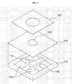
- FIG. 1 is a perspective view illustrating a structure of an optical lens according to an exemplary embodiment of the present invention.
- FIGS. 2 and 3 are an exploded perspective view and a partially cut perspective view, respectively, illustrating a structure of an optical lens according to an exemplary embodiment of the present invention.
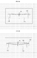
- FIG. 4 is a sectional view illustrating a structure of an optical lens according to an exemplary embodiment of the present invention.
- An optical lens according to the present invention includes a light-transmitting substrate provided with a lens chamber and a fluidic chamber, wherein the lens chamber and the fluidic chamber are connected with each other, a light-transmitting elastic film sealing the lens chamber, a buffer elastic film sealing the fluidic chamber, and an actuator provided on the buffer elastic film to correspond to the fluidic chamber, varying the volume of the fluidic chamber to vary a pressure acting on the light-transmitting elastic film.
- the light-transmitting elastic film and the buffer elastic film may be connected with each other to form a single body, or may be provided independently from each other. Also, the light-transmitting elastic film and the buffer elastic film may be formed of the same material or different materials.
- an optical lens 100 includes a light-transmitting substrate 110, a light-transmitting elastic film 120, and an actuator 130.
- the light-transmitting substrate 110 is formed of a transparent or semitransparent light-transmitting material.
- the light-transmitting substrate 110 may be formed of a transparent glass or silicon.
- the light-transmitting substrate 110 may be made from a circular wafer of a light-transmitting material, wherein the circular wafer has various sizes such as 4 inches, 6 inches, 8 inches, and 10 inches.
- a fluidic chamber 114 having a predetermined depth and a lower lens surface 112 are formed to be exposed on the light-transmitting substrate 110, wherein the lower lens surface 112 is spaced apart from the fluidic chamber 114 at a predetermined distance.
- the fluidic chamber 114 and the lower lens surface 112 are connected with each other.
- a channel 116 is formed between the fluidic chamber 114 and the lower lens surface 112.
- the channel 116 is also exposed to the top surface of the light-transmitting substrate 110.
- the fluidic chamber 114, the lower lens surface 112, and the channel 116 can be formed by etching or a mechanical process.
- the channel 116 may be formed entirely between the fluidic chamber 114 and the lower lens surface 112. Alternatively, a plurality of channels 116 may be formed at predetermined intervals.
- the channel may be formed inside the light-transmitting substrate.
- a single fluidic chamber 114 may be formed only for the lower lens surface 112. Conversely, a plurality of fluidic chambers may be formed for the lower lens surface 112, wherein the fluidic chambers are connected with one another. The number and arrangement structure of the fluidic chambers 114 may depend on required conditions and design options.
- the light-transmitting elastic film 120 is formed of a transparent or semitransparent elastic material, and is provided on the light-transmitting substrate 110 to seal the lower lens surface 112 and the fluidic chamber 114.
- An upper lens surface 122 is formed above the lower lens surface 112.
- the light-transmitting elastic film 120 may be formed of a material having the same properties as that of the light-transmitting substrate 110, or different properties from that of the light-transmitting substrate 110 (for example, refractive index and transmissivity).
- the light-transmitting elastic film 120 may be formed of PDMS, which is transparent and has excellent durability and flexibility.
- the light-transmitting elastic film 120 may be formed of elastomer.
- the light-transmitting elastic film 120 is bonded to the top surface of the light-transmitting substrate 110 in a single body by a typical adhesive or a bonding method, whereby the lower lens surface 112, the fluidic chamber 114, and the channel 116 are sealed, and a part of the light-transmitting elastic film 120 forms the upper lens surface 122 above the lower lens surface 112.
- a functional coating layer such as an antireflective coating layer and an anti-infrared coating layer, or a protective layer may be formed on the surface of the light-transmitting elastic film 120.
- the lower lens surface 112 and the upper lens surface 122 may have a convex or concave spherical structure.
- the lower lens surface 112 and the upper lens surface 122 may have a non-spherical structure.
- an optical fluid 10 such as water or oil may be injected into a sealing space sealed by the light-transmitting elastic film 120.
- an injection hole for injecting the optical fluid 10 may be formed at one side of the light-transmitting substrate 110. After the optical fluid 10 is injected into the injection hole, the injection hole is again sealed.
- the actuator 130 is provided on the light-transmitting elastic film 120 to correspond to the fluidic chamber 114, so that the pressure selectively acting on the upper lens surface 122 may be varied.
- the actuator 130 is strained to be curved up or down, and thus varies the volume of the fluidic chamber 114. Specifically, if the volume of the fluidic chamber 114 is varied by such strain of the actuator 130, the volume of the lens chamber, defined as the space between the upper lens surface 122 and the lower lens surface 112, and connected with the fluidic chamber 114, is also varied. As a result, the pressure acting on the upper lens surface 122 is varied and strain is caused, whereby a focal distance by the upper lens surface 122 and the lower lens surface 112 may be varied.
- Various related art actuators may be used as the actuator 130.
- a polymer actuator made of an EAP, which is very thin and has low power consumption, may be used as the actuator 130.
- the EAP is a material that becomes strained when a voltage is applied thereto, similar to piezoelectric material.
- the EAP differs from the piezoelectric material in that strain size of the EAP is considerably greater than that of the piezoelectric material.
- the EAP can be categorized into an EAP actuated by an electric field, an EAP actuated by static electricity, and an EAP actuated by ions.
- FIG. 5 to FIG. 7 illustrate a polymer actuator in an optical lens according to an exemplary embodiment of the present invention.
- a polymer actuator 130a includes an electrostrictive polymer such as P(VDF-TrFE) (interpolymer).
- P(VDF-TrFE) interpolymer
- electrostrictive strain similar to a piezoelectric effect is caused, whereby the polymer actuator 130a is strained to be curved up or down.
- the polymer actuator 130b may include a dielectric elastomer, such as acrylate or silicon.
- the power source is applied to electrodes provided at both sides of a dielectric elastomer layer 131 b so that a potential difference may be applied to both electrodes, whereby the dielectric elastomer layer 131 b may be strained to be curved up or down by a Maxwell force between the dielectric elastomer layer 131 b and each electrode.
- the polymer actuator 130c may include an ionic polymer such as IPMC.
- IPMC ionic polymer
- the ion polymer layer 131 c may be strained to be curved up or down by electro-osmosis, in which a positive ion inside the ion polymer layer 131 c moves to a cathode.
- FIGS. 8A and 8B illustrate the operation state of the actuator in the optical lens according to an exemplary embodiment of the present invention.
- the light-transmitting elastic film 120 formed of an elastic polymer such as PDMS has an elastic modulus lower than that of the polymer actuator 130 formed of an active polymer in the range of one several hundredth, the light-transmitting elastic film 120 does not bind the polymer actuator 130 when the polymer actuator 130 is curved, whereby the efficiency of the polymer actuator 130 can be maximized.
- the actuator 130 is directly mounted on the light-transmitting substrate 110 without passing through the light-transmitting elastic film 120, a bonded portion of the actuator 130 is bound in the light-transmitting substrate 110, whereby a strain ⁇ 1 of the actuator 130 does not occur efficiently.
- FIG. 8B if the actuator 130 is mounted on the light-transmitting substrate 110 through the light-transmitting elastic film 120, a bonded portion of the actuator 130 is also strained when the actuator 130 is curve-strained, and the light-transmitting elastic film 120 does not bind the bonded portion of the actuator 130, whereby a strain ⁇ 2 of the actuator 130 can be maximized.
- the power consumption can be minimized, and the strain and response speed of the actuator 130 can be maximized under the same power.
- FIGS. 9 and 10 illustrate a design condition of a lens portion and an actuator in an optical lens according to an exemplary embodiment of the present invention.
- a shape of the light-transmitting elastic film 120 varied by variation of the hydraulic pressure (or flow) can be approximated based on Equation 1 below.
- W r W 0 ⁇ 1 - r 2 a 2 2
- Equation 1 W(r) is displacement in a direction 'z', W O is maximum displacement in the center, and a is a radius of the lens.
- n 1 and n 2 are refractive indices of the optical fluid and the light-transmitting substrate 110, respectively, and R 1 and R 2 are curvature radiuses of the upper lens surface 122 and the lower lens surface 112, respectively.
- the first term of the right side of Equation 2 represents a dioptric power that is varied when R 1 is varied
- the second term of the right side of Equation 2 represents a dioptric power that is fixed by the lower lens surface 112.
- the polymer actuator 130 since the polymer actuator 130 includes an upper inactive area with a thickness ti and a lower active area with a thickness ta, expansion or contraction occurs in a direction vertical to an electrode when a voltage is applied to the polymer actuator 130. Also, strain occurs in a direction parallel with the electrode due to Poisson effect. Thus, curve strain is caused to the whole structure of the actuator 130.
- the height of the upper inactive area should be equal to that of the lower active area to obtain maximum strain.
- the light-transmitting elastic film 120 is efficiently used to increase the strain of the actuator 130. In other words, the efficiency of the actuator 130 which is curve-strained depends on the binding conditions of the actuator 130.
- the elastic modulus of the light-transmitting elastic film 120 is lower than that of the polymer used as the actuator 130 in the range of one several hundredth, the light-transmitting elastic film 120 does not bind the actuator 130 when the actuator 130 is curve-strained, whereby a high efficiency of the actuator 130 is obtained.
- a dioptric power of 50 D. (diopter) calculated through Equation 2 this corresponds to a driving volume of 25 nano liter
- a deflection of about 30 mm is required if the fluidic chamber 114 is 2 mm * 2 mm.
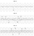
- FIG. 11 to FIG. 19 are sectional views illustrating a method for manufacturing an optical lens according to an exemplary embodiment of the present invention.
- the optical lens according to the present invention can be manufactured in a wafer-level process which includes providing a light-transmitting substrate 110 with a lower lens surface 112 and a fluidic chamber 114, the lower lens surface 112 and the fluidic chamber 114 being spaced apart from each other and connected with each other; providing a light-transmitting elastic film 120 on the light-transmitting substrate 110 to seal the lower lens surface 112 and the fluidic chamber 114 and form an upper lens surface 122 above the lower lens surface 112; providing an actuator 130 on the light-transmitting elastic film 120 to correspond to the fluidic chamber 114, the actuator 130 being strained if a power source is applied thereto; and dicing the light-transmitting substrate 110 to provide individual modules corresponding to the upper lens surface 122, the lower lens surface 112, and the fluidic chamber 114.
- the light-transmitting substrate 110 formed of a transparent or semitransparent light-transmitting material is prepared.
- the light-transmitting substrate 110 is a related art transparent glass, and may have various sizes such as 4 inches, 6 inches, 8 inches, and 10 inches.
- the fluidic chamber 114 having a predetermined depth and the lower lens surface 112 are formed to be exposed on the light-transmitting substrate 110, wherein the lower lens surface 112 is spaced apart from the fluidic chamber 114 at a predetermined distance.
- the fluidic chamber 114 and the lower lens surface 112 are connected with each other.
- the fluidic chamber 114 and the lower lens surface 112 may be connected with each other by forming a channel 116, which connects the lower lens surface 112 with the fluidic chamber 114, on the light-transmitting substrate 110 to be externally exposed.
- the fluidic chamber 114, the lower lens surface 112, and the channel 116 may be formed by etching or a mechanical process.
- the channel 116 may be formed entirely between the fluidic chamber 114 and the lower lens surface 112. Alternatively, a plurality of channels 116 may be formed at predetermined intervals. Furthermore, a single fluidic chamber 114 may be formed only for the lower lens surface 112. Conversely, a plurality of fluidic chambers may be formed for the lower lens surface 112, wherein the fluidic chambers are connected with one another.
- the lower lens surface 112 and the fluidic chamber 114 are sealed on the light-transmitting substrate 110, and the light-transmitting elastic film 120 is provided to form the upper lens surface 122 above the lower lens surface 112.
- the light-transmitting elastic film 120 may be directly formed on the light-transmitting substrate 110, the light-transmitting elastic film 120 may be bonded to the light-transmitting substrate 110 through a release sheet 141.
- the providing the light-transmitting elastic film 120 includes forming the light-transmitting elastic film 120 on the release sheet 141, bonding the light-transmitting elastic film 120 formed on the release sheet 141 to the light-transmitting substrate 110, and detaching the release sheet 141 from the light-transmitting elastic film 120.
- a hard release sheet or a soft release sheet may be used as the release sheet 141.
- the light-transmitting elastic film 120 may be formed in such a manner that a transparent or semitransparent elastic material is formed on the release sheet 141 in a thin film type by coating or spin coating.
- the light-transmitting elastic film 120 may be formed of a material having the same properties as that of the light-transmitting substrate 110, or different properties from that of the light-transmitting substrate 110 (for example, refractive index and transmissivity).
- the light-transmitting elastic film 120 may be formed of an elastomer such as PDMS, which is transparent and has excellent durability and flexibility.
- the light-transmitting elastic film 120 is bonded to the top surface of the light-transmitting substrate 110 so that the release sheet 141 is bonded thereto.
- the release sheet 141 is then detached from the light-transmitting elastic film 120, so that the light-transmitting elastic film 120 may be provided on the light-transmitting substrate 110.
- Adhesion between the release sheet 141 and the light-transmitting elastic film 120 may have one-time use adhesion, so that the release sheet 141 may selectively be detached from the light-transmitting elastic film 120. Also, adhesion between the light-transmitting elastic film 120 and the light-transmitting substrate 110 may have relatively strong adhesion in comparison with the adhesion between the release sheet 141 and the light-transmitting elastic film 120.
- a Teflon coating layer may additionally be formed on the surface of the release sheet 141 before the light-transmitting elastic film 120 is formed on the release sheet 141, to facilitate detachment between the release sheet 141 and the light-transmitting elastic film 120.
- surface treatment such as oxygen (O 2 ) plasma etching may additionally be performed on the adhesive surface between the light-transmitting elastic film 120 and the light-transmitting substrate 110 before the light-transmitting elastic film 120 is bonded to the light-transmitting substrate 110.
- the lower lens surface 112 and the upper lens surface 122 may be formed with a convex or concave spherical structure. Alternatively, the lower lens surface 112 and the upper lens surface 122 may be formed with a non-spherical structure.
- the actuator 130 is provided on the light-transmitting elastic film 120 to correspond to the fluidic chamber 114, wherein the actuator 130 is varied as the power source is applied thereto.
- Various related art actuators may be used as the actuator 130.
- a typical polymer actuator made of an EAP which is very thin and has low power consumption, may be used as the actuator 130.
- the polymer actuator include an electrostrictive polymer such as P(VDF-TrFE) (interpolymer), a dielectric elastomer such as acrylate or silicon, and an ionic polymer such as IPMC, described above with reference to FIG. 5 to FIG. 7.
- the polymer actuator 130 may directly be formed on the light-transmitting elastic film 120. Conversely, the polymer actuator 130 may be bonded to the light-transmitting elastic film 120 through a release sheet 142.
- the providing of the actuator 130 includes forming the actuator 130 on the release sheet 142, bonding the actuator 130 formed on the release sheet 142 to the light-transmitting elastic film 120, and detaching the release sheet 142 from the actuator 130.
- a hard release sheet or a soft release sheet may be used as the release sheet 142.
- the polymer actuator 130 may be formed in such a manner that a polymer and/or electrodes are sequentially deposited on the release sheet.
- the polymer actuator 130 is bonded onto the light-transmitting elastic film 120 so that the release sheet 142 is bonded thereto.
- the release sheet 142 is then detached from the actuator 130, so that the polymer actuator 130 may be provided on the light-transmitting elastic film 120.
- Adhesion between the release sheet 142 and the actuator 130 may have one-time use adhesion, so that the release sheet 142 may selectively be detached from the actuator 130. Also, adhesion between the actuator 130 and the light-transmitting elastic film 120 may have relatively strong adhesion in comparison with the adhesion between the release sheet 142 and the actuator 130.
- a Teflon coating layer may additionally be formed on the surface of the release sheet 142 before the actuator 130 is formed on the release sheet 142, to facilitate detachment between the release sheet 142 and the actuator 130.
- surface treatment such as O 2 plasma etching may additionally be performed on the adhesive surface between the actuator 130 and the light-transmitting elastic film 120 before the actuator 130 is bonded to the light-transmitting elastic film 120.
- an optical fluid 10 such as water or oil is injected into a sealing space sealed by the light-transmitting elastic film 120.
- the optical fluid 10 may be injected through an injection hole formed at one side of the light-transmitting substrate 110. After the optical fluid is injected into the injection hole, the injection hole is again sealed.
- the optical fluid is injected after the actuator 130 is bonded to the light-transmitting elastic film 120.
- the optical fluid may be injected before the actuator 130 is bonded to the light-transmitting elastic film 120.
- the light-transmitting substrate 110 is diced for each module.
- the dicing the light-transmitting substrate 110 may be performed by a general dicing device.
- the light-transmitting substrate 110 may be divided into individual modules corresponding to the upper lens surface 122, the lower lens surface 112, and the fluidic chamber 114.
- an optical lens surface may be formed on a bottom of the aforementioned light-transmitting substrate 110 or inside the light-transmitting substrate 110 to correspond to the lower lens surface 112, so that the optical lens surface may be arranged on a channel of light which passes through the lower lens surface 112.
- the optical lens surface may be formed with a convex or concave spherical structure.
- the optical lens surface may be formed with a non-spherical structure.
- the optical lens surface may be formed when the light-transmitting substrate 110 is provided.
- the optical lens surface may be formed after various parts constituting the optical lens are formed.
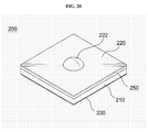
- FIG. 20 is a perspective view illustrating a structure of an optical lens according to another exemplary embodiment of the present invention.
- FIGS. 21 and 22 are an exploded perspective view and a partially cut perspective view, respsectively, illustrating a structure of an optical lens according to another embodiment of the present invention.
- FIG. 23 is a sectional view illustrating a structure of an optical lens according to another exemplary embodiment of the present invention.
- an optical lens 200 includes a light-transmitting substrate 210, a cover substrate 250, a light-transmitting elastic film 220, and an actuator 230.
- the light-transmitting substrate 210 is formed of a transparent or semitransparent light-transmitting material.
- the light-transmitting substrate 210 may be formed of a transparent glass or silicon.
- the light-transmitting substrate 210 may be made from a circular wafer of a light-transmitting material, wherein the circular wafer has various sizes such as 4 inches, 6 inches, 8 inches, and 10 inches.
- a fluidic chamber 214 having a predetermined depth and a lower lens surface 212 are formed to be exposed on the light-transmitting substrate 210, wherein the lower lens surface 212 is spaced apart from the fluidic chamber 214 at a predetermined distance.
- the fluidic chamber 214 and the lower lens surface 212 may be formed by etching or a mechanical process.
- the cover substrate 250 is tightly bonded to the top surface of the light-transmitting substrate 210 to cover an opening on the fluidic chamber 214.
- the cover substrate 250 may be formed of a material having the same properties as that of the light-transmitting substrate 210, or may be formed of a material having different properties from that of the light-transmitting substrate 210 (for example, refractive index and transmissivity). Since the cover substrate 250 is not a portion through which light is directly transmitted, unlike the light-transmitting substrate 210 provided with the lower lens surface 212, the cover substrate 250 may be formed of a material having poor light-transmitting performance.
- the cover substrate 250 may be formed of a polymer molding material, such as silicon or glass.
- the cover substrate 250 is provided with a lens hole 254 which passes through the cover substrate 250 in a thickness direction, to be arranged on the same optical axis as that of the lower lens surface 212 to correspond to the lower lens surface 212.
- the lens hole 254 may be formed by etching or a mechanical process.
- bonding between the cover substrate 250 and the light-transmitting substrate 210 may be performed by a typical bonding method.
- the cover substrate 250 and the light-transmitting substrate 210 may be bonded to each other by direct bonding without a separate adhesive.
- the cover substrate 250 and the light-transmitting substrate 210 are respectively formed of silicon and glass, the cover substrate 250 and the light-transmitting substrate 210 may be bonded to each other by anodic bonding without a separate adhesive.
- the cover substrate 250 and the light-transmitting substrate 210 may be bonded to each other by a typical adhesive.
- a channel 252 is formed at one side of opposing surfaces of the light-transmitting substrate 210 and the cover substrate 250, wherein the channel 252 serves to connect the lower lens surface 212 with the fluidic chamber 214.
- the channel 252 may be formed only on the light-transmitting substrate 210 or the cover substrate 250.
- the channels may respectively be formed at the opposing surfaces of the light-transmitting substrate 210 and the cover substrate 250 so as to cooperate with each other.
- an example of the channel 252 having a predetermined depth will be described, wherein the channel 252 is formed to be exposed to a bottom on the cover substrate 250 only opposite to the light-transmitting substrate 210.
- the channel 252 may be formed entirely between the fluidic chamber 214 and the lower lens surface 212. Alternatively, a plurality of channels 252 may be formed at predetermined intervals. Furthermore, a single fluidic chamber 214 may be formed only for the lower lens surface 212. Conversely, a plurality of fluidic chambers 214 may be formed for the lower lens surface 212, wherein the fluidic chambers 214 are connected with one another. The number and arrangement structure of the fluidic chambers 214 may depend on required conditions and design options.
- the light-transmitting elastic film 220 is formed of a transparent or semitransparent elastic material, and is provided on the cover substrate 250 to seal the lens hole 254, whereby an upper lens surface 222 is formed above the lower lens surface 212.
- the light-transmitting elastic film 220 may be formed of a material having the same properties as that of the light-transmitting substrate 210, or different properties from that of the light-transmitting substrate 210 (for example, refractive index and transmissivity).
- the light-transmitting elastic film 220 may be formed of elastomer, such as PDMS, which is transparent and has excellent durability and flexibility.
- the light-transmitting elastic film 220 may be bonded to the top surface of the cover substrate 250 in a single body by a typical adhesive or a bonding method, whereby the lens hole 254 is sealed, and a part of the light-transmitting elastic film 220 forms the upper lens surface 222 above the lower lens surface 212.
- a functional coating layer such as an antireflective coating layer and an anti-infrared coating layer, or a protective layer may be formed on the surface of the light-transmitting elastic film 220.
- the lower lens surface 212 and the upper lens surface 222 may have a convex or concave spherical structure.
- the lower lens surface 212 and the upper lens surface 222 may have a non-spherical structure.
- the actuator 230 is provided on a bottom of the light-transmitting substrate 210 to cover a lower opening of the fluidic chamber 214, so that the pressure selectively acting on the upper lens surface 222 may be varied.
- the actuator 230 is strained to be curved up or down, and thus varies the volume of the fluidic chamber 214.
- the volume of a lens chamber defined as the space between the upper lens surface 222 and the lower lens surface 212, and connected with the fluidic chamber 214, is also varied.
- the pressure acting on the upper lens surface 222 is varied and strain is caused, whereby a focal distance by the upper lens surface 222 and the lower lens surface 212 may be varied.
- a polymer actuator made of an EAP which is very thin and has low power consumption, may be used as the actuator 230.
- polymer actuator examples include an electrostrictive polymer such as P(VDF-TrFE) (interpolymer), a dielectric elastomer such as acrylate or silicon, and an ionic polymer such as IPMC.
- electrostrictive polymer such as P(VDF-TrFE) (interpolymer)
- dielectric elastomer such as acrylate or silicon
- IPMC ionic polymer
- an optical fluid 10 such as water or oil may be injected into a sealing space sealed by the light-transmitting elastic film 220 and the actuator 230.
- an injection hole for injecting the optical fluid 10 may be formed at one side of the light-transmitting substrate 210 or the cover substrate 250. After the optical fluid is injected into the injection hole, the injection hole is again sealed.
- one side of the channel 252 which connects the fluidic chamber 214 with the space between the respective lens surfaces is not formed by the light-transmitting elastic film 220 which is elastically strained, but is formed between the light-transmitting substrate 210 and the cover substrate 250 which are more rigid than the light-transmitting elastic film 220, whereby the exact amount of the fluid can be dispensed when the hydraulic pressure (or flow) is applied to the fluid.
- this structure prevents local strain from unstably occurring in a boundary portion between each of the lens surfaces 212 and 222 and the channel 252, whereby the exact amount of the fluid can uniformly be dispensed. Also, this structure reduces the motion time of the optical fluid 10 to reduce the response time required for focusing, prevents the operation pressure from rapidly increasing, and thus prevents reliability and stability from decreasing.
- FIG. 24 to FIG. 32 are sectional views illustrating a method for manufacturing an optical lens according to another exemplary embodiment of the present invention.
- the optical lens according to another exemplary embodiment of the present invention can be manufactured in a wafer-level process which includes providing a light-transmitting substrate 210 with a lower lens surface 212 and a fluidic chamber 214, and a cover substrate provided with a lens hole 254; forming a channel 252 at one side of the light-transmitting substrate 210 and the cover substrate 250, the channel 252 connecting the lower lens surface 212 with a fluidic chamber 214; bonding the cover substrate 250 to the light-transmitting substrate 210 to arrange the channel 252 between the light-transmitting substrate 210 and the cover substrate 250; providing a light-transmitting elastic film 220 on the cover substrate 250 to seal the lens hole 254 and form an upper lens surface 222 above the lower lens surface 212; providing an actuator 230 to a bottom of the light-transmitting substrate 210 to cover a lower portion of the fluidic chamber 214, the actuator 230 being strained as the power is applied thereto; and dicing the light-transmitting substrate 210 to
- the light-transmitting substrate 210 formed of a transparent or semitransparent light-transmitting material is prepared.
- the light-transmitting substrate 210 is a related art transparent glass, and may be formed at various sizes such as 4 inches, 6 inches, 8 inches, and 10 inches.
- the cover substrate 250 is prepared, which is formed of a material having the same properties as that of the light-transmitting substrate 210, or a material having different properties from that of the light-transmitting substrate 210 (for example, refractive index and transmissivity). Since the cover substrate 250 is not a portion through which light is directly transmitted, unlike the light-transmitting substrate 210 provided with the lower lens surface 212, the cover substrate 250 may be formed of a material having poor light-transmitting performance.
- the cover substrate 250 may be formed of a polymer molding material such as silicon or glass.
- the light-transmitting substrate 210 is provided with a fluidic chamber 214 and a lower lens surface 212, which are formed to be exposed to the top surface, wherein the fluidic chamber 214 and the lower lens surface 212 are spaced apart from each other.
- the cover substrate 250 is provided with a lens hole 254 which passes through the cover substrate 250 in a thickness direction to be arranged on the same optical axis as that of the lower lens surface 212 to correspond to the lower lens surface 212.
- the fluidic chamber 214, the lower lens surface 212 and the lens hole 254 may be formed by typical etching or a mechanical process.
- a channel 252 is formed at one side of opposing surfaces of the light-transmitting substrate 210 and the cover substrate 250, wherein the channel 252 serves to connect the lower lens surface 212 with the fluidic chamber 214.
- the channel 252 may be formed only on the light-transmitting substrate 210 or the cover substrate 250. Alternatively, the channels may respectively be formed at the opposing surfaces of the light-transmitting substrate 210 and the cover substrate 250.
- FIG. 25 an example of the channel 252 having a predetermined depth will be described, wherein the channel 252 is formed to be exposed to a bottom of the cover substrate 250 opposite to the light-transmitting substrate 210.
- the channel 252 may be formed entirely between the fluidic chamber 214 and the lower lens surface 212. Alternatively, a plurality of channels 252 may be formed at predetermined intervals. Furthermore, a single fluidic chamber 214 may be formed only for the lower lens surface 212. Conversely, a plurality of fluidic chambers 214 may be formed for the lower lens surface 212, wherein the fluidic chambers 214 are connected with one another. The number and arrangement structure of the fluidic chambers 214 may depend on required conditions and design options.
- the cover substrate 250 is bonded to the light-transmitting substrate 250 so that the channel 252 may be arranged between the light-transmitting substrate 210 and the cover substrate 250.
- Bonding between the cover substrate 250 and the light-transmitting substrate 210 may be performed by a typical bonding method.
- the bonding method may depend on the material of the cover substrate 250 and the light-transmitting substrate 210. For example, if the cover substrate 250 and the light-transmitting substrate 210 are formed of a typical glass, the cover substrate 250 and the light-transmitting substrate 210 may be bonded to each other by direct bonding without a separate adhesive.
- cover substrate 250 and the light-transmitting substrate 210 are respectively formed of silicon and glass, the cover substrate 250 and the light-transmitting substrate 210 may be bonded to each other by anodic bonding without a separate adhesive. In addition, the cover substrate 250 and the light-transmitting substrate 210 may be bonded to each other by a typical adhesive.
- the lens hole 254 is sealed on the cover substrate 250, and the light-transmitting elastic film 220 is provided to form the upper lens surface 222 above the lower lens surface 212.
- the light-transmitting elastic film 220 may be directly formed on the cover substrate 250, the light-transmitting elastic film 220 may be bonded to the cover substrate 250 through a release sheet 242.
- the providing the light-transmitting elastic film 220 includes forming the light-transmitting elastic film 220 on the release sheet 242, bonding the light-transmitting elastic film 220 formed on the release sheet 242 to the cover substrate 250, and detaching the release sheet 242 from the light-transmitting elastic film 220, as described with reference to FIGS. 13 and 14.
- a hard release sheet or a soft release sheet may be used as the release sheet 242.
- the light-transmitting elastic film 220 may be formed in such a manner that a transparent or semitransparent elastic material is formed on the release sheet 242 in a thin film type by coating or spin coating.
- the light-transmitting elastic film 220 may be formed of a material having the same properties as that of the light-transmitting substrate 210, or a material having different properties from that of the light-transmitting substrate 210 (for example, refractive index and transmissivity).
- the light-transmitting elastic film 220 may be formed of elastomer such as PDMS, which is transparent and has excellent durability and flexibility.
- the light-transmitting elastic film 220 is bonded onto the cover substrate 250 so that the release sheet is bonded thereto.
- the release sheet 242 is then detached from the light-transmitting elastic film 220, so that the light-transmitting elastic film 220 may be provided on the cover substrate 250.
- Adhesion between the release sheet 242 and the light-transmitting elastic film 220 may have one-time use adhesion, so that the release sheet may selectively be detached from the light-transmitting elastic film 220. Also, adhesion between the light-transmitting elastic film 220 and the cover substrate 250 may have relatively strong adhesion in comparison with the adhesion between the release sheet 242 and the light-transmitting elastic film 220.
- a Teflon coating layer may additionally be formed on the surface of the release sheet 242 before the light-transmitting elastic film 220 is formed on the release sheet 242, to facilitate detachment between the release sheet and the light-transmitting elastic film 220.
- surface treatment such as O 2 plasma etching may additionally be performed on the adhesive surface between the light-transmitting elastic film 220 and the cover substrate 250 before the light-transmitting elastic film 220 is bonded to the cover substrate 250.
- the lower lens surface 212 and the upper lens surface 222 formed on the light-transmitting substrate 210 and the light-transmitting elastic film 220 may be formed with a convex or concave spherical structure.
- the lower lens surface 212 and the upper lens surface 222 may be formed with a non-spherical structure.
- the actuator 230 is provided on a bottom of the light-transmitting substrate 210 to correspond to the fluidic chamber 214, wherein the actuator 230 is varied as the power source is applied thereto.
- Various related art actuators may be used as the actuator 230.
- a typical polymer actuator made of an EAP which is very thin and has low power consumption, may be used as the actuator 230.
- the polymer actuator include an electrostrictive polymer such as P(VDF-TrFE) (interpolymer), a dielectric elastomer such as acrylate or silicon, and an ionic polymer such as IPMC.
- the polymer actuator 230 may be formed directly on the light-transmitting substrate 210. Conversely, the polymer actuator 230 may be bonded to the light-transmitting substrate 210 through a release sheet 242.
- the providing the actuator 230 includes forming the actuator 230 on the release sheet 242, bonding the actuator 230 formed on the release sheet 242 to the light-transmitting substrate 210, and detaching the release sheet 242 from the actuator 230.
- a hard release sheet or a soft release sheet may be used as the release sheet 242.
- the polymer actuator 230 may be formed in such a manner that a polymer and/or electrodes are sequentially deposited on the release sheet 242.
- the polymer actuator 230 is bonded onto a bottom of the light-transmitting substrate 210 so that the release sheet 242 is bonded thereto.
- the release sheet 242 is then detached from the actuator 230, so that the polymer actuator 230 may be provided on the light-transmitting substrate 210.
- Adhesion between the release sheet 242 and the actuator 230 may have one-time use adhesion, so that the release sheet 242 may selectively be detached from the actuator 230. Also, adhesion between the actuator 230 and the light-transmitting substrate 210 may have relatively strong adhesion in comparison with the adhesion between the release sheet 242 and the actuator 230.
- a Teflon coating layer may additionally be formed on the surface of the release sheet 242 before the actuator 230 is formed on the release sheet 242, to facilitate detachment between the release sheet 242 and the actuator 230.
- surface treatment such as O 2 plasma etching may additionally be performed on the adhesive surface between the actuator 230 and the light-transmitting elastic film 220 before the actuator 230 is bonded to the light-transmitting substrate 210.
- an optical fluid 10 such as water or oil is injected into a sealing space sealed by the light-transmitting elastic film 220 and the actuator 230.
- the optical fluid 10 may be injected through an injection hole formed at one side of the light-transmitting substrate 210 or the cover substrate 250. After the optical fluid is injected into the injection hole, the injection hole is again sealed.
- the optical fluid 10 is injected after the actuator 230 is bonded to the light-transmitting substrate 210.
- the optical fluid may be injected before the actuator 230 is bonded to the light-transmitting substrate 210.
- the light-transmitting substrate 210 is diced for each module.
- the dicing the light-transmitting substrate 210 may be performed by a general dicing device.
- the light-transmitting substrate 210 may be divided into individual modules corresponding to the upper lens surface 222, the lower lens surface 212, and the fluidic chamber 214.
- an optical lens surface may be formed on a bottom of the aforementioned light-transmitting substrate 210 or inside the light-transmitting substrate 210 to correspond to the lower lens surface 212, so that the optical lens surface may be arranged on a channel of light which passes through the lower lens surface 212.
- the optical lens surface may be formed with a convex or concave spherical structure.
- the optical lens surface may be formed with a non-spherical structure.
- the optical lens surface may be formed when the light-transmitting substrate 210 is provided.
- the optical lens surface may be formed after various parts constituting the optical lens 200 are formed.
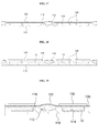
- FIG. 33 to FIG. 35 are sectional views illustrating a structure of an optical lens according to another exemplary embodiment of the present invention.
- the same or like reference numbers will be used throughout the drawings to refer to the same or like parts, and their detailed description will be omitted.
- a buffer elastic film 320 may be provided on a bottom of the light-transmitting substrate 210 before the actuator 230 is bonded to a bottom of the light-transmitting substrate 210, as shown in FIG. 33.
- the buffer elastic film 320 may be formed of the same material as the light-transmitting elastic film 220, or a different material from the light-transmitting elastic film 220. Since the buffer elastic film 320 is not a portion through which light is directly transmitted, unlike the light-transmitting elastic film 220, the buffer elastic film 320 may be formed of a material having poor light-transmitting performance.
- the buffer elastic film 320 may be formed of a material having an elastic modulus equivalent to that of the light-transmitting elastic film 220, to improve efficiency of the actuator 230.
- the actuator 130 is provided at one side of the upper or lower portions of the fluidic chamber
- the actuators 130 may respectively be formed at the upper or lower portions of the fluidic chamber 114 as shown in FIG. 34, so that the actuators 130 may be independently driven.
- the optical lens surface 118 may be formed on a bottom of the light-transmitting substrate 110 to correspond to the lower lens surface 112, so that the optical lens surface 118 may be arranged on a channel of light which passes through the lower lens surface 112.
- the optical lens surface 118 may have a convex or concave spherical structure.
- the optical lens surface 118 may have a non-spherical structure.
- the optical lens surface may be formed inside the light-transmitting substrate.
- the optical lens and a method for manufacturing the same according to the present invention have the following advantages.
- the optical lens Since the structure of the optical lens and its manufacturing process are simplified, the optical lens can be manufactured with miniaturization and thin size, the cost can be reduced, and productivity can be improved.
- the optical lens can be manufactured in a wafer-level process, it is advantageous in view of mass production, and the manufacturing cost can be reduced to reduce the cost of the product.
- the product can be manufactured to be small and slim.
- the actuator is provided through the elastic film having a relatively low elastic modulus, the power consumption is minimized, and the strain of the actuator can be maximized under the same power.
- the fluid can uniformly be dispensed when the hydraulic pressure (or flow) is applied to the fluid, it is possible to prevent reliability and stability from decreasing.
Priority Applications (2)
| Application Number | Priority Date | Filing Date | Title |
|---|---|---|---|
| EP09165195A EP2105768B1 (de) | 2006-11-13 | 2007-04-02 | Flüssige optische Linse mit einem elektrostriktiven Polymer Antrieb |
| EP10174974A EP2270555B1 (de) | 2006-11-13 | 2007-04-02 | Optische Flüssiglinse mit einem elastichen Pufferfilm |
Applications Claiming Priority (1)
| Application Number | Priority Date | Filing Date | Title |
|---|---|---|---|
| KR1020060111723A KR20080043106A (ko) | 2006-11-13 | 2006-11-13 | 광학렌즈 및 그 제조방법 |
Related Child Applications (2)
| Application Number | Title | Priority Date | Filing Date |
|---|---|---|---|
| EP09165195A Division EP2105768B1 (de) | 2006-11-13 | 2007-04-02 | Flüssige optische Linse mit einem elektrostriktiven Polymer Antrieb |
| EP09165195.0 Division-Into | 2009-07-10 |
Publications (2)
| Publication Number | Publication Date |
|---|---|
| EP1921471A1 true EP1921471A1 (de) | 2008-05-14 |
| EP1921471B1 EP1921471B1 (de) | 2010-09-08 |
Family
ID=38820355
Family Applications (3)
| Application Number | Title | Priority Date | Filing Date |
|---|---|---|---|
| EP07105471A Expired - Fee Related EP1921471B1 (de) | 2006-11-13 | 2007-04-02 | Optische Linse und Herstellungsverfahren dafür |
| EP10174974A Expired - Fee Related EP2270555B1 (de) | 2006-11-13 | 2007-04-02 | Optische Flüssiglinse mit einem elastichen Pufferfilm |
| EP09165195A Expired - Fee Related EP2105768B1 (de) | 2006-11-13 | 2007-04-02 | Flüssige optische Linse mit einem elektrostriktiven Polymer Antrieb |
Family Applications After (2)
| Application Number | Title | Priority Date | Filing Date |
|---|---|---|---|
| EP10174974A Expired - Fee Related EP2270555B1 (de) | 2006-11-13 | 2007-04-02 | Optische Flüssiglinse mit einem elastichen Pufferfilm |
| EP09165195A Expired - Fee Related EP2105768B1 (de) | 2006-11-13 | 2007-04-02 | Flüssige optische Linse mit einem elektrostriktiven Polymer Antrieb |
Country Status (5)
| Country | Link |
|---|---|
| US (1) | US7580195B2 (de) |
| EP (3) | EP1921471B1 (de) |
| JP (1) | JP4823137B2 (de) |
| KR (1) | KR20080043106A (de) |
| DE (1) | DE602007009017D1 (de) |
Cited By (11)
| Publication number | Priority date | Publication date | Assignee | Title |
|---|---|---|---|---|
| EP2199836A1 (de) * | 2008-12-18 | 2010-06-23 | BAE Systems PLC | Fluidlinse |
| EP2409486A1 (de) * | 2009-03-18 | 2012-01-25 | Bayer MaterialScience AG | Optisches system auf waferebene |
| WO2012010201A1 (en) * | 2010-07-20 | 2012-01-26 | Fraunhofer-Gesellschaft zur Förderung der angewandten Forschung e.V. | Fluidic variable focal length optical lens and method for manufacturing the same |
| EP2431770A1 (de) * | 2010-09-21 | 2012-03-21 | Commissariat à l'Énergie Atomique et aux Énergies Alternatives | Vorrichtung mit verformbarer Membran zur Betätigung mit verkürzter Reaktionszeit |
| DE102012215113A1 (de) * | 2012-08-24 | 2014-02-27 | Osram Opto Semiconductors Gmbh | Organische Leuchtdiode und Verfahren zum Betreiben einer organischen Leuchtdiode |
| US8717681B2 (en) | 2008-12-18 | 2014-05-06 | Bae Systems, Plc | Fluidic lens |
| CN104603678A (zh) * | 2012-06-29 | 2015-05-06 | 庄臣及庄臣视力保护公司 | 多态电活性眼科装置 |
| DE102015101688A1 (de) * | 2015-02-05 | 2016-08-11 | Osram Oled Gmbh | Organische Leuchtdiodenvorrichtung |
| CN108614353A (zh) * | 2018-05-10 | 2018-10-02 | 西安交通大学 | 基于离子交换聚合金属材料的二维偏转解耦机构及其偏转方法 |
| CN112014911A (zh) * | 2020-09-15 | 2020-12-01 | 东南大学 | 一种可变焦液体透镜及其设计方法和制作方法 |
| CN112068308A (zh) * | 2020-09-15 | 2020-12-11 | 东南大学 | 一种电驱动片型可变焦镜头及其设计方法和制作方法 |
Families Citing this family (107)
| Publication number | Priority date | Publication date | Assignee | Title |
|---|---|---|---|---|
| US7697214B2 (en) | 2005-05-14 | 2010-04-13 | Holochip Corporation | Fluidic lens with manually-adjustable focus |
| ES2687620T3 (es) | 2007-05-04 | 2018-10-26 | Opko Diagnostics, Llc | Dispositivo y método para análisis en sistemas microfluídicos |
| EP2034338A1 (de) * | 2007-08-11 | 2009-03-11 | ETH Zurich | Flüssiglinsesystem |
| WO2009123266A1 (ja) | 2008-04-03 | 2009-10-08 | コニカミノルタホールディングス株式会社 | 撮像装置、および撮像装置の製造方法 |
| US8866920B2 (en) | 2008-05-20 | 2014-10-21 | Pelican Imaging Corporation | Capturing and processing of images using monolithic camera array with heterogeneous imagers |
| US11792538B2 (en) | 2008-05-20 | 2023-10-17 | Adeia Imaging Llc | Capturing and processing of images including occlusions focused on an image sensor by a lens stack array |
| EP4336447A1 (de) | 2008-05-20 | 2024-03-13 | FotoNation Limited | Aufnahme und verarbeitung von bildern mittels monolithischer kamera anordnung mit heterogenem bildwandler |
| WO2010015093A1 (en) | 2008-08-08 | 2010-02-11 | Optotune Ag | Electroactive optical device |
| JP2010048993A (ja) * | 2008-08-21 | 2010-03-04 | Fujinon Corp | 積層型カメラモジュールの製造方法および積層型カメラモジュール並びに撮像装置。 |
| AT507236B1 (de) * | 2008-09-12 | 2010-06-15 | Swarovski Optik Kg | Schutzkappe |
| EP2192425A1 (de) | 2008-11-26 | 2010-06-02 | Samsung Electronics Co., Ltd. | Linse mit variabler Brennweite und Verfahren zu deren Herstellung |
| JP5422986B2 (ja) * | 2008-12-10 | 2014-02-19 | コニカミノルタ株式会社 | 駆動装置および撮像装置 |
| KR101508727B1 (ko) * | 2008-12-30 | 2015-04-06 | 삼성전자 주식회사 | 가변초점 광학렌즈 |
| TR201815133T4 (tr) * | 2009-02-02 | 2018-11-21 | Opko Diagnostics Llc | Mikrofilidik cihazlar ile ışık etkileşiminin kontrol edilmesi için yapılar. |
| US20100208194A1 (en) | 2009-02-13 | 2010-08-19 | Amitava Gupta | Variable focus liquid filled lens apparatus |
| US8087778B2 (en) | 2009-02-13 | 2012-01-03 | Adlens Beacon, Inc. | Variable focus liquid filled lens mechanism |
| US8659835B2 (en) | 2009-03-13 | 2014-02-25 | Optotune Ag | Lens systems and method |
| US8699141B2 (en) | 2009-03-13 | 2014-04-15 | Knowles Electronics, Llc | Lens assembly apparatus and method |
| US9164202B2 (en) | 2010-02-16 | 2015-10-20 | Holochip Corporation | Adaptive optical devices with controllable focal power and aspheric shape |
| US20110038625A1 (en) * | 2009-08-13 | 2011-02-17 | Strategic Polymer Sciences, Inc. | Electromechanical polymer actuators |
| KR101648540B1 (ko) * | 2009-08-13 | 2016-08-16 | 삼성전자주식회사 | 웨이퍼-레벨 렌즈 모듈 및 이를 구비하는 촬상 장치 |
| KR101680300B1 (ko) | 2009-08-31 | 2016-11-28 | 삼성전자주식회사 | 액체 렌즈 및 그 제조방법 |
| KR101675130B1 (ko) | 2009-09-03 | 2016-11-10 | 삼성전자주식회사 | 액체 렌즈 |
| FR2950154B1 (fr) * | 2009-09-15 | 2011-12-23 | Commissariat Energie Atomique | Dispositif optique a membrane deformable a actionnement piezoelectrique en forme de couronne continue |
| US8414121B2 (en) * | 2009-10-13 | 2013-04-09 | Adlens Beacon, Inc. | Non-round fluid filled lens optic |
| US8817381B2 (en) | 2009-10-13 | 2014-08-26 | Adlens Beacon, Inc. | Full field membrane design for non-round liquid lens assemblies |
| US8136942B2 (en) * | 2009-10-14 | 2012-03-20 | Adlens Beacon, Inc. | Aspheric fluid filled lens optic |
| US8596781B2 (en) * | 2009-10-15 | 2013-12-03 | Adlens Beacon, Inc. | Fluid filled lens reservoir system and manufacturing method of the reservoir system |
| US8353593B2 (en) | 2009-10-15 | 2013-01-15 | Adlens Beacon, Inc. | Hinge mechanism for a fluid filled lens assembly |
| MX2012004396A (es) | 2009-10-15 | 2012-08-17 | Adlens Beacon Inc | Lentes rellenos con fluido y mecanismos de inflamiento de los mismos. |
| EP2502115A4 (de) | 2009-11-20 | 2013-11-06 | Pelican Imaging Corp | Aufnahme und verarbeitung von bildern mittels eines monolithischen kameraarrays mit heterogenem bildwandler |
| US20120012748A1 (en) | 2010-05-12 | 2012-01-19 | Pelican Imaging Corporation | Architectures for imager arrays and array cameras |
| EP2239600A1 (de) | 2010-06-02 | 2010-10-13 | Optotune AG | Einstellbare optische Linse |
| FR2962557B1 (fr) * | 2010-07-12 | 2013-06-07 | Commissariat Energie Atomique | Procede de fabrication d'un dispositif a membrane emprisonnant un fluide |
| US9036264B2 (en) | 2010-08-12 | 2015-05-19 | Adlens Beacon, Inc. | Fluid-filled lenses and their ophthalmic applications |
| US8944647B2 (en) | 2010-09-02 | 2015-02-03 | Optotune Ag | Illumination source with variable divergence |
| KR101912092B1 (ko) * | 2010-10-05 | 2018-10-26 | 삼성전자 주식회사 | 액체 렌즈 |
| EP3486710A3 (de) | 2010-10-11 | 2019-07-17 | Adlens Beacon, Inc. | Nicht stromgetriebene konzepte für ein drahtgestell mit flüssigkeitsgefüllten linsen |
| USD665009S1 (en) | 2010-10-14 | 2012-08-07 | Adlens Beacon, Inc. | Spectacles frame |
| WO2012055049A1 (en) | 2010-10-26 | 2012-05-03 | Optotune Ag | Variable focus lens having two liquid chambers |
| KR101912093B1 (ko) | 2010-10-29 | 2018-10-26 | 삼성전자 주식회사 | 광학 장치 |
| WO2012064955A2 (en) | 2010-11-10 | 2012-05-18 | William Egan | Fluid-filled lenses and actuation systems thereof |
| US8878950B2 (en) | 2010-12-14 | 2014-11-04 | Pelican Imaging Corporation | Systems and methods for synthesizing high resolution images using super-resolution processes |
| KR101826745B1 (ko) | 2010-12-14 | 2018-02-07 | 삼성전자주식회사 | 가변초점 렌즈 구조체 및 그 제조방법과, 광학렌즈 모듈 및 그 제조방법 |
| KR101804473B1 (ko) | 2010-12-16 | 2017-12-04 | 삼성전자주식회사 | 가변초점 렌즈 구조체 및 그 제조방법 |
| CN107404609B (zh) | 2011-05-11 | 2020-02-11 | 快图有限公司 | 用于传送阵列照相机图像数据的方法 |
| US20130265459A1 (en) | 2011-06-28 | 2013-10-10 | Pelican Imaging Corporation | Optical arrangements for use with an array camera |
| KR101852030B1 (ko) | 2011-08-25 | 2018-04-25 | 삼성전자주식회사 | 마이크로 소자의 웨이퍼 레벨 보호 구조물과 이를 포함하는 마이크로 소자 및 이들의 제조방법 |
| WO2013043751A1 (en) | 2011-09-19 | 2013-03-28 | Pelican Imaging Corporation | Systems and methods for controlling aliasing in images captured by an array camera for use in super resolution processing using pixel apertures |
| CN104081414B (zh) | 2011-09-28 | 2017-08-01 | Fotonation开曼有限公司 | 用于编码和解码光场图像文件的系统及方法 |
| EP2817955B1 (de) | 2012-02-21 | 2018-04-11 | FotoNation Cayman Limited | Systeme und verfahren zur manipulation von bilddaten aus einem erfassten lichtfeld |
| BR112014021776B1 (pt) | 2012-03-05 | 2022-08-09 | Opko Diagnostics, Llc | Sistema de ensaio e método para a determinação de uma probabilidade de um evento associado com o câncer da próstata |
| US9210392B2 (en) | 2012-05-01 | 2015-12-08 | Pelican Imaging Coporation | Camera modules patterned with pi filter groups |
| WO2014005123A1 (en) | 2012-06-28 | 2014-01-03 | Pelican Imaging Corporation | Systems and methods for detecting defective camera arrays, optic arrays, and sensors |
| US20140002674A1 (en) | 2012-06-30 | 2014-01-02 | Pelican Imaging Corporation | Systems and Methods for Manufacturing Camera Modules Using Active Alignment of Lens Stack Arrays and Sensors |
| US9535264B2 (en) | 2012-07-13 | 2017-01-03 | Adlens Beacon, Inc. | Fluid lenses, lens blanks, and methods of manufacturing the same |
| EP3869797B1 (de) | 2012-08-21 | 2023-07-19 | Adeia Imaging LLC | Verfahren zur tiefenerkennung in mit array-kameras aufgenommenen bildern |
| WO2014032020A2 (en) | 2012-08-23 | 2014-02-27 | Pelican Imaging Corporation | Feature based high resolution motion estimation from low resolution images captured using an array source |
| CN104685860A (zh) | 2012-09-28 | 2015-06-03 | 派力肯影像公司 | 利用虚拟视点从光场生成图像 |
| WO2014078443A1 (en) | 2012-11-13 | 2014-05-22 | Pelican Imaging Corporation | Systems and methods for array camera focal plane control |
| US9462164B2 (en) | 2013-02-21 | 2016-10-04 | Pelican Imaging Corporation | Systems and methods for generating compressed light field representation data using captured light fields, array geometry, and parallax information |
| WO2014133974A1 (en) | 2013-02-24 | 2014-09-04 | Pelican Imaging Corporation | Thin form computational and modular array cameras |
| US9917998B2 (en) | 2013-03-08 | 2018-03-13 | Fotonation Cayman Limited | Systems and methods for measuring scene information while capturing images using array cameras |
| US8866912B2 (en) | 2013-03-10 | 2014-10-21 | Pelican Imaging Corporation | System and methods for calibration of an array camera using a single captured image |
| US9106784B2 (en) | 2013-03-13 | 2015-08-11 | Pelican Imaging Corporation | Systems and methods for controlling aliasing in images captured by an array camera for use in super-resolution processing |
| WO2014164550A2 (en) | 2013-03-13 | 2014-10-09 | Pelican Imaging Corporation | System and methods for calibration of an array camera |
| US9888194B2 (en) | 2013-03-13 | 2018-02-06 | Fotonation Cayman Limited | Array camera architecture implementing quantum film image sensors |
| US9519972B2 (en) | 2013-03-13 | 2016-12-13 | Kip Peli P1 Lp | Systems and methods for synthesizing images from image data captured by an array camera using restricted depth of field depth maps in which depth estimation precision varies |
| WO2014159779A1 (en) | 2013-03-14 | 2014-10-02 | Pelican Imaging Corporation | Systems and methods for reducing motion blur in images or video in ultra low light with array cameras |
| US9100586B2 (en) | 2013-03-14 | 2015-08-04 | Pelican Imaging Corporation | Systems and methods for photometric normalization in array cameras |
| US10122993B2 (en) | 2013-03-15 | 2018-11-06 | Fotonation Limited | Autofocus system for a conventional camera that uses depth information from an array camera |
| US9445003B1 (en) | 2013-03-15 | 2016-09-13 | Pelican Imaging Corporation | Systems and methods for synthesizing high resolution images using image deconvolution based on motion and depth information |
| US9497370B2 (en) | 2013-03-15 | 2016-11-15 | Pelican Imaging Corporation | Array camera architecture implementing quantum dot color filters |
| US9438888B2 (en) | 2013-03-15 | 2016-09-06 | Pelican Imaging Corporation | Systems and methods for stereo imaging with camera arrays |
| US9497429B2 (en) | 2013-03-15 | 2016-11-15 | Pelican Imaging Corporation | Extended color processing on pelican array cameras |
| WO2015048694A2 (en) | 2013-09-27 | 2015-04-02 | Pelican Imaging Corporation | Systems and methods for depth-assisted perspective distortion correction |
| US9426343B2 (en) | 2013-11-07 | 2016-08-23 | Pelican Imaging Corporation | Array cameras incorporating independently aligned lens stacks |
| KR20150054288A (ko) | 2013-11-11 | 2015-05-20 | 삼성전자주식회사 | 가변 액체 렌즈 시스템 |
| US10119808B2 (en) | 2013-11-18 | 2018-11-06 | Fotonation Limited | Systems and methods for estimating depth from projected texture using camera arrays |
| EP3075140B1 (de) | 2013-11-26 | 2018-06-13 | FotoNation Cayman Limited | Zeilenkamerakonfigurationen mit mehreren zeilenkameras |
| US10089740B2 (en) | 2014-03-07 | 2018-10-02 | Fotonation Limited | System and methods for depth regularization and semiautomatic interactive matting using RGB-D images |
| US9521319B2 (en) | 2014-06-18 | 2016-12-13 | Pelican Imaging Corporation | Array cameras and array camera modules including spectral filters disposed outside of a constituent image sensor |
| WO2016003367A1 (en) * | 2014-07-02 | 2016-01-07 | Heptagon Micro Optics Pte. Ltd. | Techniques for reducing distortion of optical beam shaping elements |
| CN113256730B (zh) | 2014-09-29 | 2023-09-05 | 快图有限公司 | 用于阵列相机的动态校准的系统和方法 |
| US9676522B1 (en) * | 2015-01-09 | 2017-06-13 | Robert M. Stovall | Portable cooler with contoured bottom |
| US9942474B2 (en) | 2015-04-17 | 2018-04-10 | Fotonation Cayman Limited | Systems and methods for performing high speed video capture and depth estimation using array cameras |
| GB2542638A (en) * | 2015-09-28 | 2017-03-29 | Adiens Ltd | An adjustable fluid-filled lens assembly and method for assembling the same |
| DE102015226173A1 (de) * | 2015-12-21 | 2017-06-22 | Robert Bosch Gmbh | Optisches Abbildungssystem mit einer aufgrund elektrischer und/oder magnetischer Kräfte verformbaren Linse |
| CN109073792B (zh) | 2016-04-29 | 2021-07-09 | Lg伊诺特有限公司 | 相机模块以及包括相机模块的光学装置 |
| KR20180088237A (ko) * | 2017-01-26 | 2018-08-03 | 엘지이노텍 주식회사 | 액체 렌즈 모듈, 이를 포함하는 카메라 모듈 및 액체 렌즈 모듈의 제조 방법 |
| US10482618B2 (en) | 2017-08-21 | 2019-11-19 | Fotonation Limited | Systems and methods for hybrid depth regularization |
| JP7273250B2 (ja) | 2019-09-17 | 2023-05-12 | ボストン ポーラリメトリックス,インコーポレイティド | 偏光キューを用いた面モデリングのためのシステム及び方法 |
| DE112020004813B4 (de) | 2019-10-07 | 2023-02-09 | Boston Polarimetrics, Inc. | System zur Erweiterung von Sensorsystemen und Bildgebungssystemen mit Polarisation |
| KR20230116068A (ko) | 2019-11-30 | 2023-08-03 | 보스턴 폴라리메트릭스, 인크. | 편광 신호를 이용한 투명 물체 분할을 위한 시스템및 방법 |
| CN111025627A (zh) * | 2020-01-10 | 2020-04-17 | 太原理工大学 | 一种基于pdms薄膜的全固态可变焦静电驱动式微透镜 |
| US11195303B2 (en) | 2020-01-29 | 2021-12-07 | Boston Polarimetrics, Inc. | Systems and methods for characterizing object pose detection and measurement systems |
| KR20220133973A (ko) | 2020-01-30 | 2022-10-05 | 인트린식 이노베이션 엘엘씨 | 편광된 이미지들을 포함하는 상이한 이미징 양식들에 대해 통계적 모델들을 훈련하기 위해 데이터를 합성하기 위한 시스템들 및 방법들 |
| CN111239864B (zh) * | 2020-02-13 | 2023-08-22 | 北京理工大学 | 一种三明治结构的介电弹性微流体液体透镜及制作方法 |
| CN111399213B (zh) * | 2020-03-30 | 2021-02-02 | 北京理工大学 | 基于介电弹性体和液体双驱动的光束偏转器 |
| WO2021243088A1 (en) | 2020-05-27 | 2021-12-02 | Boston Polarimetrics, Inc. | Multi-aperture polarization optical systems using beam splitters |
| CN111948777A (zh) * | 2020-07-10 | 2020-11-17 | 东南大学 | 一种基于介电弹性体的可变焦腔型镜头 |
| CN112162338A (zh) * | 2020-11-20 | 2021-01-01 | 太原师范学院 | 一种基于ipmc驱动的全固态可调焦微透镜 |
| CN112925052B (zh) * | 2021-01-29 | 2022-11-08 | 青岛大学 | 基于介电弹性体驱动器的焦距可调式透镜及其制备方法 |
| US11954886B2 (en) | 2021-04-15 | 2024-04-09 | Intrinsic Innovation Llc | Systems and methods for six-degree of freedom pose estimation of deformable objects |
| US11290658B1 (en) | 2021-04-15 | 2022-03-29 | Boston Polarimetrics, Inc. | Systems and methods for camera exposure control |
| CN115598788A (zh) * | 2021-06-28 | 2023-01-13 | 华为技术有限公司(Cn) | 透镜装置、电子设备及制备该透镜装置的方法和掩模版 |
| US11689813B2 (en) | 2021-07-01 | 2023-06-27 | Intrinsic Innovation Llc | Systems and methods for high dynamic range imaging using crossed polarizers |
Citations (4)
| Publication number | Priority date | Publication date | Assignee | Title |
|---|---|---|---|---|
| JPH08114703A (ja) * | 1994-10-13 | 1996-05-07 | Nippondenso Co Ltd | 可変焦点レンズ |
| JPH10144975A (ja) * | 1996-11-08 | 1998-05-29 | Denso Corp | 積層型圧電アクチュエータおよび可変焦点レンズ装置 |
| US5917657A (en) * | 1996-02-22 | 1999-06-29 | Denso Corp | Imaging device having flexible liquid-filled film lens |
| WO2002014926A2 (en) * | 2000-08-15 | 2002-02-21 | Nanostream, Inc. | Optical devices with fluidic systems |
Family Cites Families (13)
| Publication number | Priority date | Publication date | Assignee | Title |
|---|---|---|---|---|
| JPH06308303A (ja) * | 1993-04-19 | 1994-11-04 | Kanagawa Kagaku Gijutsu Akad | 可変焦点レンズ及びその駆動装置 |
| JPH0749404A (ja) * | 1993-08-05 | 1995-02-21 | Nippondenso Co Ltd | 可変焦点レンズ |
| JPH10269599A (ja) | 1997-03-26 | 1998-10-09 | Denso Corp | 光ピックアップ装置 |
| JPH11133210A (ja) * | 1997-10-30 | 1999-05-21 | Denso Corp | 可変焦点レンズ |
| JP4106576B2 (ja) * | 1998-08-31 | 2008-06-25 | 株式会社デンソー | 可変焦点レンズ |
| KR100374205B1 (ko) | 2000-01-03 | 2003-03-04 | 한국과학기술원 | 초소형 굴절 실리콘 렌즈 제조방법 |
| JP3687585B2 (ja) | 2001-10-05 | 2005-08-24 | オムロン株式会社 | 焦点可変レンズ装置 |
| KR100486727B1 (ko) | 2002-11-14 | 2005-05-03 | 삼성전자주식회사 | 평판형 렌즈의 제조방법 |
| CN1732401A (zh) | 2002-12-30 | 2006-02-08 | 皇家飞利浦电子股份有限公司 | 含有聚合物致动器的光学装置 |
| KR100783582B1 (ko) | 2004-08-19 | 2007-12-11 | 인하대학교 산학협력단 | 광신호 접속부 및 광신호 접속부의 초점거리 조절방법 |
| KR100762992B1 (ko) | 2004-09-24 | 2007-10-02 | 엘지전자 주식회사 | 렌즈구동장치 |
| US7554743B2 (en) * | 2006-05-30 | 2009-06-30 | Wisconsin Alumni Research Foundation | Variable-focus lens assembly |
| NO326372B1 (no) * | 2006-09-21 | 2008-11-17 | Polight As | Polymerlinse |
-
2006
- 2006-11-13 KR KR1020060111723A patent/KR20080043106A/ko active Search and Examination
-
2007
- 2007-03-22 US US11/723,875 patent/US7580195B2/en not_active Expired - Fee Related
- 2007-04-02 EP EP07105471A patent/EP1921471B1/de not_active Expired - Fee Related
- 2007-04-02 DE DE602007009017T patent/DE602007009017D1/de active Active
- 2007-04-02 EP EP10174974A patent/EP2270555B1/de not_active Expired - Fee Related
- 2007-04-02 EP EP09165195A patent/EP2105768B1/de not_active Expired - Fee Related
- 2007-05-02 JP JP2007121895A patent/JP4823137B2/ja not_active Expired - Fee Related
Patent Citations (4)
| Publication number | Priority date | Publication date | Assignee | Title |
|---|---|---|---|---|
| JPH08114703A (ja) * | 1994-10-13 | 1996-05-07 | Nippondenso Co Ltd | 可変焦点レンズ |
| US5917657A (en) * | 1996-02-22 | 1999-06-29 | Denso Corp | Imaging device having flexible liquid-filled film lens |
| JPH10144975A (ja) * | 1996-11-08 | 1998-05-29 | Denso Corp | 積層型圧電アクチュエータおよび可変焦点レンズ装置 |
| WO2002014926A2 (en) * | 2000-08-15 | 2002-02-21 | Nanostream, Inc. | Optical devices with fluidic systems |
Cited By (20)
| Publication number | Priority date | Publication date | Assignee | Title |
|---|---|---|---|---|
| EP2199836A1 (de) * | 2008-12-18 | 2010-06-23 | BAE Systems PLC | Fluidlinse |
| US8717681B2 (en) | 2008-12-18 | 2014-05-06 | Bae Systems, Plc | Fluidic lens |
| EP2409486A4 (de) * | 2009-03-18 | 2012-08-22 | Bayer Materialscience Ag | Optisches system auf waferebene |
| EP2409486A1 (de) * | 2009-03-18 | 2012-01-25 | Bayer MaterialScience AG | Optisches system auf waferebene |
| US9250367B2 (en) | 2010-07-20 | 2016-02-02 | Fraunhofer-Gesellschaft Zur Foerderung Der Angewandten Forschung E.V. | Fluidic variable focal length optical lens and method for manufacturing the same |
| WO2012010201A1 (en) * | 2010-07-20 | 2012-01-26 | Fraunhofer-Gesellschaft zur Förderung der angewandten Forschung e.V. | Fluidic variable focal length optical lens and method for manufacturing the same |
| US8422142B2 (en) | 2010-09-21 | 2013-04-16 | Commissariat A L'energie Atomique Et Aux Energies Alternatives | Membrane device the membrane of which can be deformed by actuation with a fast response time |
| EP2431770A1 (de) * | 2010-09-21 | 2012-03-21 | Commissariat à l'Énergie Atomique et aux Énergies Alternatives | Vorrichtung mit verformbarer Membran zur Betätigung mit verkürzter Reaktionszeit |
| FR2965068A1 (fr) * | 2010-09-21 | 2012-03-23 | Commissariat Energie Atomique | Dispositif a membrane deformable par actionnement a temps de reponse reduit |
| EP3282291A1 (de) * | 2010-09-21 | 2018-02-14 | Webster Capital LLC | Vorrichtung mit verformbarer membran zur betätigung mit verkürzter reaktionszeit |
| CN110095886A (zh) * | 2012-06-29 | 2019-08-06 | 庄臣及庄臣视力保护公司 | 多态电活性眼科装置 |
| CN104603678A (zh) * | 2012-06-29 | 2015-05-06 | 庄臣及庄臣视力保护公司 | 多态电活性眼科装置 |
| DE102012215113A1 (de) * | 2012-08-24 | 2014-02-27 | Osram Opto Semiconductors Gmbh | Organische Leuchtdiode und Verfahren zum Betreiben einer organischen Leuchtdiode |
| DE102012215113B4 (de) | 2012-08-24 | 2022-02-03 | Pictiva Displays International Limited | Organische Leuchtdiode und Verfahren zum Betreiben einer organischen Leuchtdiode |
| DE102015101688A1 (de) * | 2015-02-05 | 2016-08-11 | Osram Oled Gmbh | Organische Leuchtdiodenvorrichtung |
| US10147773B2 (en) | 2015-02-05 | 2018-12-04 | Osram Oled Gmbh | Organic light-emitting diode device |
| DE102015101688B4 (de) | 2015-02-05 | 2022-12-15 | Pictiva Displays International Limited | Organische Leuchtdiodenvorrichtung |
| CN108614353A (zh) * | 2018-05-10 | 2018-10-02 | 西安交通大学 | 基于离子交换聚合金属材料的二维偏转解耦机构及其偏转方法 |
| CN112014911A (zh) * | 2020-09-15 | 2020-12-01 | 东南大学 | 一种可变焦液体透镜及其设计方法和制作方法 |
| CN112068308A (zh) * | 2020-09-15 | 2020-12-11 | 东南大学 | 一种电驱动片型可变焦镜头及其设计方法和制作方法 |
Also Published As
| Publication number | Publication date |
|---|---|
| EP2105768A3 (de) | 2009-10-28 |
| US7580195B2 (en) | 2009-08-25 |
| JP2008122909A (ja) | 2008-05-29 |
| EP2105768B1 (de) | 2012-05-16 |
| KR20080043106A (ko) | 2008-05-16 |
| US20080112059A1 (en) | 2008-05-15 |
| EP1921471B1 (de) | 2010-09-08 |
| EP2270555A1 (de) | 2011-01-05 |
| JP4823137B2 (ja) | 2011-11-24 |
| EP2105768A2 (de) | 2009-09-30 |
| DE602007009017D1 (de) | 2010-10-21 |
| EP2270555B1 (de) | 2013-02-13 |
Similar Documents
| Publication | Publication Date | Title |
|---|---|---|
| EP1921471B1 (de) | Optische Linse und Herstellungsverfahren dafür | |
| KR101403676B1 (ko) | 광학 렌즈 및 그 제조방법 | |
| US7773306B2 (en) | Electrowetting cells | |
| JP5487201B2 (ja) | 特に変形膜を持つ光学素子のための改良された膜 | |
| US7382545B2 (en) | Liquid zoom lens | |
| EP2338072B1 (de) | Elektroaktive optische vorrichtung | |
| KR101496157B1 (ko) | 중합체 렌즈 | |
| KR100711247B1 (ko) | 액체 줌 렌즈 | |
| US20100232028A1 (en) | Optical element and lens array | |
| US20080137213A1 (en) | Electrowetting Cell and Method for Driving it | |
| KR20060058020A (ko) | 가변 초점 길이 렌즈 | |
| JP2009518676A (ja) | 流体フォーカスレンズにおける溶液流の防止 | |
| KR20100078705A (ko) | 가변초점 광학렌즈 | |
| US8004771B2 (en) | Varifocal lens and method of manufacturing the same | |
| KR100847802B1 (ko) | 비구면 액체 렌즈 및 그 제조 방법 | |
| US20110222163A1 (en) | Varifocal lens and liquid filling method for manufacturing same | |
| Choi et al. | Liquid-filled varifocal lens on a chip | |
| JP3687585B2 (ja) | 焦点可変レンズ装置 | |
| KR101675108B1 (ko) | 가변 초점 렌즈 및 그 제조방법 | |
| CN113467072A (zh) | 可变焦距光学元件 | |
| KR20070008169A (ko) | 액체 렌즈 | |
| KR100843371B1 (ko) | 액체 렌즈 모듈 |
Legal Events
| Date | Code | Title | Description |
|---|---|---|---|
| PUAI | Public reference made under article 153(3) epc to a published international application that has entered the european phase |
Free format text: ORIGINAL CODE: 0009012 |
|
| 17P | Request for examination filed |
Effective date: 20070425 |
|
| AK | Designated contracting states |
Kind code of ref document: A1 Designated state(s): AT BE BG CH CY CZ DE DK EE ES FI FR GB GR HU IE IS IT LI LT LU LV MC MT NL PL PT RO SE SI SK TR |
|
| AX | Request for extension of the european patent |
Extension state: AL BA HR MK RS |
|
| 17Q | First examination report despatched |
Effective date: 20081208 |
|
| AKX | Designation fees paid |
Designated state(s): DE FR GB |
|
| GRAP | Despatch of communication of intention to grant a patent |
Free format text: ORIGINAL CODE: EPIDOSNIGR1 |
|
| GRAS | Grant fee paid |
Free format text: ORIGINAL CODE: EPIDOSNIGR3 |
|
| GRAA | (expected) grant |
Free format text: ORIGINAL CODE: 0009210 |
|
| AK | Designated contracting states |
Kind code of ref document: B1 Designated state(s): DE FR GB |
|
| REG | Reference to a national code |
Ref country code: GB Ref legal event code: FG4D |
|
| REF | Corresponds to: |
Ref document number: 602007009017 Country of ref document: DE Date of ref document: 20101021 Kind code of ref document: P |
|
| PLBE | No opposition filed within time limit |
Free format text: ORIGINAL CODE: 0009261 |
|
| STAA | Information on the status of an ep patent application or granted ep patent |
Free format text: STATUS: NO OPPOSITION FILED WITHIN TIME LIMIT |
|
| 26N | No opposition filed |
Effective date: 20110609 |
|
| REG | Reference to a national code |
Ref country code: DE Ref legal event code: R097 Ref document number: 602007009017 Country of ref document: DE Effective date: 20110609 |
|
| REG | Reference to a national code |
Ref country code: FR Ref legal event code: PLFP Year of fee payment: 9 |
|
| PGFP | Annual fee paid to national office [announced via postgrant information from national office to epo] |
Ref country code: FR Payment date: 20150316 Year of fee payment: 9 Ref country code: GB Payment date: 20150316 Year of fee payment: 9 |
|
| PGFP | Annual fee paid to national office [announced via postgrant information from national office to epo] |
Ref country code: DE Payment date: 20150316 Year of fee payment: 9 |
|
| REG | Reference to a national code |
Ref country code: DE Ref legal event code: R119 Ref document number: 602007009017 Country of ref document: DE |
|
| GBPC | Gb: european patent ceased through non-payment of renewal fee |
Effective date: 20160402 |
|
| REG | Reference to a national code |
Ref country code: FR Ref legal event code: ST Effective date: 20161230 |
|
| PG25 | Lapsed in a contracting state [announced via postgrant information from national office to epo] |
Ref country code: DE Free format text: LAPSE BECAUSE OF NON-PAYMENT OF DUE FEES Effective date: 20161101 Ref country code: GB Free format text: LAPSE BECAUSE OF NON-PAYMENT OF DUE FEES Effective date: 20160402 Ref country code: FR Free format text: LAPSE BECAUSE OF NON-PAYMENT OF DUE FEES Effective date: 20160502 |