EP1918482B1 - Befestigungssystem für tafelförmige Paneele - Google Patents
Befestigungssystem für tafelförmige Paneele Download PDFInfo
- Publication number
- EP1918482B1 EP1918482B1 EP07020876.4A EP07020876A EP1918482B1 EP 1918482 B1 EP1918482 B1 EP 1918482B1 EP 07020876 A EP07020876 A EP 07020876A EP 1918482 B1 EP1918482 B1 EP 1918482B1
- Authority
- EP
- European Patent Office
- Prior art keywords
- panels
- layer
- profiles
- retaining
- retaining profiles
- Prior art date
- Legal status (The legal status is an assumption and is not a legal conclusion. Google has not performed a legal analysis and makes no representation as to the accuracy of the status listed.)
- Not-in-force
Links
- 239000010410 layer Substances 0.000 claims description 39
- 239000000835 fiber Substances 0.000 claims description 6
- 239000012790 adhesive layer Substances 0.000 claims description 4
- 230000005489 elastic deformation Effects 0.000 claims description 3
- 239000011521 glass Substances 0.000 claims description 2
- 239000002184 metal Substances 0.000 claims description 2
- 239000002245 particle Substances 0.000 claims description 2
- 239000004576 sand Substances 0.000 claims description 2
- 239000004575 stone Substances 0.000 claims description 2
- 238000009408 flooring Methods 0.000 claims 1
- 230000013011 mating Effects 0.000 description 4
- 238000005452 bending Methods 0.000 description 3
- 239000002131 composite material Substances 0.000 description 3
- 238000003780 insertion Methods 0.000 description 3
- 230000037431 insertion Effects 0.000 description 3
- 230000000295 complement effect Effects 0.000 description 2
- 244000144992 flock Species 0.000 description 2
- 229910000679 solder Inorganic materials 0.000 description 2
- 238000005352 clarification Methods 0.000 description 1
- 238000010276 construction Methods 0.000 description 1
- 230000007423 decrease Effects 0.000 description 1
- 230000000694 effects Effects 0.000 description 1
- 210000003746 feather Anatomy 0.000 description 1
- 238000009434 installation Methods 0.000 description 1
- 238000009413 insulation Methods 0.000 description 1
- 229920001296 polysiloxane Polymers 0.000 description 1
Images
Classifications
-
- E—FIXED CONSTRUCTIONS
- E04—BUILDING
- E04F—FINISHING WORK ON BUILDINGS, e.g. STAIRS, FLOORS
- E04F15/00—Flooring
- E04F15/02—Flooring or floor layers composed of a number of similar elements
-
- E—FIXED CONSTRUCTIONS
- E04—BUILDING
- E04F—FINISHING WORK ON BUILDINGS, e.g. STAIRS, FLOORS
- E04F15/00—Flooring
- E04F15/02—Flooring or floor layers composed of a number of similar elements
- E04F15/04—Flooring or floor layers composed of a number of similar elements only of wood or with a top layer of wood, e.g. with wooden or metal connecting members
-
- E—FIXED CONSTRUCTIONS
- E04—BUILDING
- E04F—FINISHING WORK ON BUILDINGS, e.g. STAIRS, FLOORS
- E04F2201/00—Joining sheets or plates or panels
- E04F2201/01—Joining sheets, plates or panels with edges in abutting relationship
- E04F2201/0153—Joining sheets, plates or panels with edges in abutting relationship by rotating the sheets, plates or panels around an axis which is parallel to the abutting edges, possibly combined with a sliding movement
-
- E—FIXED CONSTRUCTIONS
- E04—BUILDING
- E04F—FINISHING WORK ON BUILDINGS, e.g. STAIRS, FLOORS
- E04F2201/00—Joining sheets or plates or panels
- E04F2201/08—Joining sheets or plates or panels hook and loop-type fastener or similar fixing means
Definitions
- the invention relates to a fastening system for tabular panels, in particular for rectangular floor panels, arranged on narrow sides of the panels holding profiles extending in the longitudinal direction of the narrow sides and of which oppositely arranged holding profiles match each other such that similar panels are connected to each other, a continuous layer to produce from panels in a laying plane.
- the holding profiles have a surface and a counter surface with a friction-increasing layer and are formed such that a lateral pulling apart composite holding profiles transversely to the longitudinal extent of the holding profiles and parallel to the laying plane to a relative movement between surface and counter surface and a pressure or an increase in pressure between the surface and the counter surface leads.
- one of the support profiles has a groove and a protrusion located therebelow, the upwardly facing top of which slightly rises from the groove to a free end of the protrusion and is provided with a friction-enhancing layer.
- the other retaining profile has an insertable into the groove spring and a recess below the spring.
- a downwardly facing bottom of the recess cooperates in the assembled state of the retaining profiles with the top of the projection, wherein the underside of the recess also has an inclination relative to the laying plane, the inclination the top of the projection corresponds.
- the upper side of the projection and the underside of the recess each form an inclined plane, which is pressed against the other oblique plane when the retaining profiles are pulled sideways, which increases the normal force between these two surfaces and thus also the frictional force which counteracts the lateral sliding apart. Consequently, the top of the projection and the bottom of the recess form the surface and mating surface with the friction-enhancing layer.
- DE 203 19 121 U1 discloses a set of tabular panels having a fastening system with retaining profiles disposed on narrow sides of the panels that extend in the longitudinal direction of the narrow sides and of which oppositely disposed retaining profiles mate with one another such that similar panels are connectable to one another to form a continuous layer of panels in a laying plane to produce, wherein the holding profiles have at least one surface and a mating surface with at least one friction-increasing layer and are formed such that s lateral pulling apart composite holding profiles transversely to the longitudinal extent of the holding profiles and parallel to the laying plane to a relative movement between the surface and counter surface and a pressure increase between Surface and counter surface leads.
- the EP 1 416 103 A1 discloses a set of tabular panels with a fastening system according to the preamble of claim 1.
- connection of the holding profiles of US 6,808,772 B2 proves to be sufficient, as far as the panels are exactly in one plane and a pulling apart of the holding profiles takes place parallel to the laying plane.
- connection of the holding profiles is often exposed to a multi-axis load.
- a weight force from above on the connection act, by which the composite holding profiles are slightly twisted or tilted about an upper abutment edge of the panels relative to each other. This is possible if the panels are laid on relatively soft subfloors, as they are known for the sound insulation. With a load from above and the concomitant rotation of the holding profiles thereby reduces the holding force of the holding profiles in a lateral pulling apart.
- the invention is therefore based on the object to provide a fastening system for tabular panels of the type mentioned above, which are simple in construction and offer great security against lateral sliding apart of the holding profiles.
- the fastening system according to claim 1 is characterized in that a rotation of a holding profile relative to the other holding profile assembled with the holding profile around the upper abutment edge, which runs parallel to the longitudinal extension of the holding profiles, counteracts a force through which the surface and the mating surface to each other being held.
- This force is preferably produced by elastically deforming the retaining profiles when the retaining profiles rotate relative to the upper abutment edge.
- the elastic deformation of the holding profiles thereby causes the rotation of the holding profiles not at all or only takes place so that surface and counter surface are not pressed apart by the rotation of the holding profiles and thus the friction between the surface and counter surface, which are overcome in the lateral pulling apart of the holding profiles must, does not fall away.
- the rotation of the retaining profile with respect to the other retaining profile should be a rotation in which an angle between the tops of the panels of 180 degrees, which is given when the panels are exactly in the laying plane , decreases by a certain amount, for example, 2 degrees to 178 degrees.
- at least one of the two holding profiles is no longer exactly in the laying plane, but is pivoted to this a little upwards around the upper edge of the installation.
- the friction-increasing layer comprises a plastic layer and / or an adhesive layer.
- the plastic layer of soft plastic such as silicone.
- small particles of sand, stone, glass or metal are embedded or the friction-increasing layer is formed as a flocking layer.
- the flocking layer may comprise a base layer and flocking fibers fixed to the base layer at a fixed end and facing away from the base layer with a loose end, the flocking fibers being oriented perpendicular to the base layer or at an angle other than 90 °.
- the orientation of the flock fibers can are suitably adjusted so that the orientation of the flock fibers has a component which precludes a direction of movement when pulling the holding profiles.
- the friction-increasing layer when pulling the holding profiles a greater coefficient of friction than when nesting of the holding profiles.
- Surface and mating surface are each formed as an inclined plane with respect to the laying plane
- An angle between the laying plane and the inclined plane may be only a few degrees, for example 0.5 to 3 °.
- a preferred possibility is to arrange the inclined plane so that it is arranged below the upper abutment edge.
- a perpendicular from the upper abutment edge would divide the oblique plane into two areas.
- the solder extends perpendicular to the laying plane, which extends in floor panels in the horizontal.
- the retaining profiles have a groove with a lower groove side wall and with an upper groove side wall and a spring with a lower side and an upper side, wherein the spring engages in a groove when the retaining profiles are connected to each other.
- the upper side of the spring on the upper groove side wall and the underside of the spring on the lower groove side wall abut, so that a weight bearing on the connection weight can be forwarded by the holding profiles without bending moments on the subfloor, as far as it is a rigid Underground acts.
- the upper groove side wall, the top of the spring form the surface or the counter surface with the friction-enhancing layer.
- surface and counter surface each have an inclined plane, which is inclined to the laying plane.
- the top of the spring and the upper groove side wall may be inclined so that when pulling out the spring from the groove, the top of the spring is pressed against the upper groove side wall.
- the spring is supported by the underside on the upper groove inner wall.
- the spring may have a chamfer at a free end.
- the groove may also have a corresponding chamfer.
- the underside of the spring has a convex curvature and the lower groove inner wall has a concave curvature of complementary design, so that an articulated connection is produced about an axis of rotation parallel to the retaining profiles. Due to the curvature, there is an undercut parallel to the laying plane, which helps to prevent the retaining profiles from being pulled apart parallel to the laying plane.
- the convex curvature and the concave curvature follow a section of a circle whose center lies below the upper abutment edge.
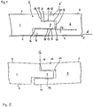
- FIG. 1 shows in cross section cutouts of a first panel 1 and a second panel 2.
- the panels 1, 2 each have a panel top 3 and a panel bottom 4.
- the panel undersides 4 of the panels 1, 2 rest on a subfloor 5.
- a fastening profile 6 is provided, which with a in the essentially complementary formed retaining profile 6 'of the second panel 2 cooperates.
- the holding profile 6 has a spring 7 with a bottom 8 and a top 9. While the upper side 9 of the spring 7 extends parallel to the lower floor 5 and thus to a laying plane E in which the panels 1, 2 lie, the underside 8 of the spring has an angle ⁇ which lies in a range between 0 and 3 degrees ,
- the retaining profile 6 For receiving the spring 7 of the retaining profile 6, the retaining profile 6 'has a groove 10 which is bounded by a lower lip 11 and an upper lip 12.
- the lower lip 11 forms a lower groove inner wall 13, while the upper lip 12 defines an upper groove inner wall 14.
- the panels 1, 2 abut an upper (common) abutment edge 15. To ensure this, free spaces 16, 17, 18 are provided, which in the assembled position (as in FIG. 1 shown) between the holding profiles 6, 6 'set.
- underside 8 of the spring 7 and the lower groove inner wall 13 is inclined by the inclination angle ⁇ to the laying plane E.
- underside 8 of the spring 7 and the lower groove inner wall 13 each form an inclined plane with respect to the laying plane E.
- a friction-increasing layer in the form of a flocking layer 19 is applied between the underside 8 and the lower groove inner wall 13. By this flocking layer 19, the friction between the surfaces 8, 13 is increased.
- the spring 7 on the top 9 a chamfer 20, which facilitates insertion of the spring 7 in the groove 10. Due to the inclination of the bottom 8 of the spring 7 and the inclination of the groove inner wall 13, the spring 7 is compressed during insertion into the groove 10 to a certain extent and the lips 11, 12 pressed apart.
- the fastening profiles 6, 6 ' can be designed so that they are in the in FIG. 1 shown assembled position virtually stress-free abut each other.
- a solder from the upper abutment edge 15 (ie extending perpendicularly from the upper side 3) divides the inclined planes 8, 13 into two areas.
- the lower lip 11 extends beyond the upper abutment edge 15.
- FIG. 2 shows the holding profiles 1, 2 in a mutually tilted or rotated position. This tilting or rotation of the panels 1, 2 to each other, for example, arise when a weight G from above on the connection of the holding profiles 6, 6 'loads. The rotation takes place around the upper contact edge 15 of the fastening profiles 6, 6 '.
- the holding profiles 6, 6 ' By the rotation of the panel 1 relative to the panel 2, the holding profiles 6, 6 'are elastically deformed. In the presentation of the FIG. 2 the holding profiles 6, 6 'are not shown deformed, so that it is in FIG. 2 to certain overlaps of the holding profiles 6, 6 'comes. These coverings do not occur in reality, their representation is merely intended to illustrate that a rotation about the upper abutment edge 15 has deformations result.
- the spring 7 is subjected to bending, which is supported on the likewise stressed bending on the lower lip 11.
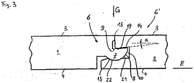
- FIG. 3 shows an embodiment of the invention. Components or features that correspond to corresponding components or features of the embodiment of Figures 1 and 2 are similar or identical are marked with the same reference numerals.
- a spring 7 and a groove 10 form a hinge, wherein the underside 8 of the spring 7 has a convex curvature 21 which is received by a concave curvature 22 of the lower groove inner wall 13.
- the bulges 21, 22 follow a section of a circle, whose center is below the upper abutment edge 15.
- FIG. 3 In the embodiment of FIG. 3 are a top 9 of the spring 7 and cooperating with them upper groove inner wall 14 formed as inclined planes, between which the friction-increasing flocking layer 19 is located.
Landscapes
- Engineering & Computer Science (AREA)
- Architecture (AREA)
- Civil Engineering (AREA)
- Structural Engineering (AREA)
- Floor Finish (AREA)
- Road Paving Structures (AREA)
Priority Applications (1)
| Application Number | Priority Date | Filing Date | Title |
|---|---|---|---|
| PL07020876T PL1918482T3 (pl) | 2006-11-04 | 2007-10-25 | System mocowań do paneli arkuszowych |
Applications Claiming Priority (1)
| Application Number | Priority Date | Filing Date | Title |
|---|---|---|---|
| DE200610052081 DE102006052081A1 (de) | 2006-11-04 | 2006-11-04 | Befestigungssystem für tafelförmige Paneele |
Publications (3)
| Publication Number | Publication Date |
|---|---|
| EP1918482A2 EP1918482A2 (de) | 2008-05-07 |
| EP1918482A3 EP1918482A3 (de) | 2013-05-01 |
| EP1918482B1 true EP1918482B1 (de) | 2016-12-28 |
Family
ID=38998807
Family Applications (1)
| Application Number | Title | Priority Date | Filing Date |
|---|---|---|---|
| EP07020876.4A Not-in-force EP1918482B1 (de) | 2006-11-04 | 2007-10-25 | Befestigungssystem für tafelförmige Paneele |
Country Status (3)
| Country | Link |
|---|---|
| EP (1) | EP1918482B1 (pl) |
| DE (1) | DE102006052081A1 (pl) |
| PL (1) | PL1918482T3 (pl) |
Citations (3)
| Publication number | Priority date | Publication date | Assignee | Title |
|---|---|---|---|---|
| WO2003016656A1 (fr) * | 2001-08-14 | 2003-02-27 | Espace Production International Epi (Societe Anonyme A Directoire Et Conseil De Surveillance) | Procede d'assemblage des bords a repartition de forces |
| EP1416103A1 (de) * | 2002-10-31 | 2004-05-06 | Li Co. GmbH | Bodenbelag umfassend miteinander verbindbare Bodenplatten |
| EP2281974A2 (en) * | 2001-01-12 | 2011-02-09 | Välinge Innovation AB | Flooring system comprising mechanically joinable floorboards |
Family Cites Families (9)
| Publication number | Priority date | Publication date | Assignee | Title |
|---|---|---|---|---|
| US7008890B1 (en) | 1995-04-19 | 2006-03-07 | Fraunhofer-Gesellschaft Zur Forderung Der Angewandten Forschung E.V. | Vapor barrier for use in the thermal insulation of buildings |
| US6808777B2 (en) * | 1996-11-08 | 2004-10-26 | Ab Golvabia | Flooring |
| SE508165C2 (sv) * | 1996-11-18 | 1998-09-07 | Golvabia Ab | Anordning för sammanfogning av golvbeläggningsmaterial |
| DE20001225U1 (de) * | 2000-01-14 | 2000-07-27 | Hornitex Werke Gebr. Künnemeyer GmbH & Co. KG, 32805 Horn-Bad Meinberg | Profil zum formschlüssigen, leimfreien und wieder lösbaren Verbinden von Fußbodendielen, Paneel oder ähnlichen Bauteilen |
| HU223627B1 (hu) * | 2000-03-07 | 2004-10-28 | E.F.P. Floor Products Fussböden GmbH. | Burkolóelemek mechanikai kötése |
| DE10302727B4 (de) | 2003-01-23 | 2005-04-14 | E.F.P. Floor Products Fussböden GmbH | Paneel, insbesondere Fußbodenpaneel |
| DE10329686B4 (de) * | 2003-07-02 | 2008-02-28 | Akzenta Paneele + Profile Gmbh | Paneel mit Verriegelungssystem |
| DE202004017921U1 (de) * | 2003-12-02 | 2005-01-27 | Kronospan Ag | Auszieh-Widerstand für Elemente |
| DE102004054368A1 (de) * | 2004-11-10 | 2006-05-11 | Kaindl Flooring Gmbh | Verkleidungspaneel |
-
2006
- 2006-11-04 DE DE200610052081 patent/DE102006052081A1/de not_active Withdrawn
-
2007
- 2007-10-25 PL PL07020876T patent/PL1918482T3/pl unknown
- 2007-10-25 EP EP07020876.4A patent/EP1918482B1/de not_active Not-in-force
Patent Citations (3)
| Publication number | Priority date | Publication date | Assignee | Title |
|---|---|---|---|---|
| EP2281974A2 (en) * | 2001-01-12 | 2011-02-09 | Välinge Innovation AB | Flooring system comprising mechanically joinable floorboards |
| WO2003016656A1 (fr) * | 2001-08-14 | 2003-02-27 | Espace Production International Epi (Societe Anonyme A Directoire Et Conseil De Surveillance) | Procede d'assemblage des bords a repartition de forces |
| EP1416103A1 (de) * | 2002-10-31 | 2004-05-06 | Li Co. GmbH | Bodenbelag umfassend miteinander verbindbare Bodenplatten |
Also Published As
| Publication number | Publication date |
|---|---|
| EP1918482A3 (de) | 2013-05-01 |
| PL1918482T3 (pl) | 2017-06-30 |
| DE102006052081A1 (de) | 2008-05-08 |
| EP1918482A2 (de) | 2008-05-07 |
Similar Documents
| Publication | Publication Date | Title |
|---|---|---|
| EP2459815B1 (de) | Belag aus mechanisch miteinander verbindbaren paneelen | |
| DE102009041297B4 (de) | Belag aus mechanisch miteinander verbindbaren Elementen und ein Verfahren zur Herstellung von Elementen | |
| DE10206877B4 (de) | Paneel, insbesondere Fussbodenpaneel | |
| EP1428957B1 (de) | Verfahren zur Verlegung und Verriegelung von Paneelen | |
| EP1380710B1 (de) | Fussbodenpaneel und Verfahren zum Verlegen eines Fussbodens | |
| EP1128000A2 (de) | Paneel, insbesondere Fussbodenpaneel | |
| EP1223265A2 (de) | Parkettplatte | |
| DE20002413U1 (de) | Verbindung | |
| DE102008021970B4 (de) | Paneel mit vereinfachtem Rastelement | |
| EP2054566B1 (de) | Befestigungssystem für tafelförmige paneele | |
| EP3708739A1 (de) | Hartes fussbodenpaneel zur schwimmenden verlegung unter ausbildung eines fussbodenpaneelverbundes | |
| EP4133140B1 (de) | Paneel mit bruchfesten koppelelementen | |
| DE202010017748U1 (de) | Belag aus mechanisch miteinander verbindbaren Elementen | |
| EP2221431B1 (de) | Einrichtung zum Verbinden von Bodenpaneelen | |
| EP2112297A2 (de) | Verbindung für Fussbodenpaneele | |
| EP3420158B1 (de) | Einrichtung zum verriegeln zweier bodenpaneele | |
| DE10038662A1 (de) | Verbindung | |
| DE102015113349A1 (de) | Fußbodenprofilanordnung und Basisprofil | |
| EP1918482A2 (de) | Befestigungssystem für tafelförmige Paneele | |
| EP3080365B1 (de) | Paneel mit verriegelungselement | |
| DE102010050005B4 (de) | Verbindungselement für Bodenelemente von Fahrzeugen | |
| DE10253236B4 (de) | Fussbodenpaneel und Verfahren zum Verlegen eines Fussbodenpaneels | |
| DE202004009645U1 (de) | Dichtungsprofil aus einem anorganischen Elastomer | |
| DE102007046598B4 (de) | Paneel | |
| DE10112958B4 (de) | Fussbodenpaneel |
Legal Events
| Date | Code | Title | Description |
|---|---|---|---|
| PUAI | Public reference made under article 153(3) epc to a published international application that has entered the european phase |
Free format text: ORIGINAL CODE: 0009012 |
|
| AK | Designated contracting states |
Kind code of ref document: A2 Designated state(s): AT BE BG CH CY CZ DE DK EE ES FI FR GB GR HU IE IS IT LI LT LU LV MC MT NL PL PT RO SE SI SK TR |
|
| AX | Request for extension of the european patent |
Extension state: AL BA HR MK RS |
|
| RAP1 | Party data changed (applicant data changed or rights of an application transferred) |
Owner name: AGEPAN TARKETT LAMINATE PARK GMBH & CO.KG |
|
| RAP1 | Party data changed (applicant data changed or rights of an application transferred) |
Owner name: LAMINATEPARK GMBH & CO. KG |
|
| PUAL | Search report despatched |
Free format text: ORIGINAL CODE: 0009013 |
|
| AK | Designated contracting states |
Kind code of ref document: A3 Designated state(s): AT BE BG CH CY CZ DE DK EE ES FI FR GB GR HU IE IS IT LI LT LU LV MC MT NL PL PT RO SE SI SK TR |
|
| AX | Request for extension of the european patent |
Extension state: AL BA HR MK RS |
|
| RIC1 | Information provided on ipc code assigned before grant |
Ipc: E04F 15/02 20060101AFI20130328BHEP |
|
| 17P | Request for examination filed |
Effective date: 20131029 |
|
| RBV | Designated contracting states (corrected) |
Designated state(s): AT BE BG CH CY CZ DE DK EE ES FI FR GB GR HU IE IS IT LI LT LU LV MC MT NL PL PT RO SE SI SK TR |
|
| AKX | Designation fees paid |
Designated state(s): AT BE BG CH CY CZ DE DK EE ES FI FR GB GR HU IE IS IT LI LT LU LV MC MT NL PL PT RO SE SI SK TR |
|
| 17Q | First examination report despatched |
Effective date: 20140213 |
|
| REG | Reference to a national code |
Ref country code: DE Ref legal event code: R079 Ref document number: 502007015349 Country of ref document: DE Free format text: PREVIOUS MAIN CLASS: E04F0015020000 Ipc: E04F0015040000 |
|
| GRAP | Despatch of communication of intention to grant a patent |
Free format text: ORIGINAL CODE: EPIDOSNIGR1 |
|
| RIC1 | Information provided on ipc code assigned before grant |
Ipc: E04F 15/04 20060101AFI20160701BHEP Ipc: E04F 15/02 20060101ALI20160701BHEP |
|
| INTG | Intention to grant announced |
Effective date: 20160729 |
|
| GRAS | Grant fee paid |
Free format text: ORIGINAL CODE: EPIDOSNIGR3 |
|
| STAA | Information on the status of an ep patent application or granted ep patent |
Free format text: STATUS: GRANT OF PATENT IS INTENDED |
|
| GRAA | (expected) grant |
Free format text: ORIGINAL CODE: 0009210 |
|
| STAA | Information on the status of an ep patent application or granted ep patent |
Free format text: STATUS: THE PATENT HAS BEEN GRANTED |
|
| AK | Designated contracting states |
Kind code of ref document: B1 Designated state(s): AT BE BG CH CY CZ DE DK EE ES FI FR GB GR HU IE IS IT LI LT LU LV MC MT NL PL PT RO SE SI SK TR |
|
| REG | Reference to a national code |
Ref country code: GB Ref legal event code: FG4D Free format text: NOT ENGLISH |
|
| REG | Reference to a national code |
Ref country code: CH Ref legal event code: EP |
|
| REG | Reference to a national code |
Ref country code: AT Ref legal event code: REF Ref document number: 857435 Country of ref document: AT Kind code of ref document: T Effective date: 20170115 |
|
| REG | Reference to a national code |
Ref country code: IE Ref legal event code: FG4D Free format text: LANGUAGE OF EP DOCUMENT: GERMAN |
|
| REG | Reference to a national code |
Ref country code: DE Ref legal event code: R096 Ref document number: 502007015349 Country of ref document: DE |
|
| PG25 | Lapsed in a contracting state [announced via postgrant information from national office to epo] |
Ref country code: LV Free format text: LAPSE BECAUSE OF FAILURE TO SUBMIT A TRANSLATION OF THE DESCRIPTION OR TO PAY THE FEE WITHIN THE PRESCRIBED TIME-LIMIT Effective date: 20161228 |
|
| REG | Reference to a national code |
Ref country code: SE Ref legal event code: TRGR |
|
| REG | Reference to a national code |
Ref country code: LT Ref legal event code: MG4D |
|
| PG25 | Lapsed in a contracting state [announced via postgrant information from national office to epo] |
Ref country code: LT Free format text: LAPSE BECAUSE OF FAILURE TO SUBMIT A TRANSLATION OF THE DESCRIPTION OR TO PAY THE FEE WITHIN THE PRESCRIBED TIME-LIMIT Effective date: 20161228 Ref country code: GR Free format text: LAPSE BECAUSE OF FAILURE TO SUBMIT A TRANSLATION OF THE DESCRIPTION OR TO PAY THE FEE WITHIN THE PRESCRIBED TIME-LIMIT Effective date: 20170329 |
|
| REG | Reference to a national code |
Ref country code: NL Ref legal event code: MP Effective date: 20161228 |
|
| PG25 | Lapsed in a contracting state [announced via postgrant information from national office to epo] |
Ref country code: FI Free format text: LAPSE BECAUSE OF FAILURE TO SUBMIT A TRANSLATION OF THE DESCRIPTION OR TO PAY THE FEE WITHIN THE PRESCRIBED TIME-LIMIT Effective date: 20161228 |
|
| PG25 | Lapsed in a contracting state [announced via postgrant information from national office to epo] |
Ref country code: NL Free format text: LAPSE BECAUSE OF FAILURE TO SUBMIT A TRANSLATION OF THE DESCRIPTION OR TO PAY THE FEE WITHIN THE PRESCRIBED TIME-LIMIT Effective date: 20161228 |
|
| PG25 | Lapsed in a contracting state [announced via postgrant information from national office to epo] |
Ref country code: IS Free format text: LAPSE BECAUSE OF FAILURE TO SUBMIT A TRANSLATION OF THE DESCRIPTION OR TO PAY THE FEE WITHIN THE PRESCRIBED TIME-LIMIT Effective date: 20170428 Ref country code: EE Free format text: LAPSE BECAUSE OF FAILURE TO SUBMIT A TRANSLATION OF THE DESCRIPTION OR TO PAY THE FEE WITHIN THE PRESCRIBED TIME-LIMIT Effective date: 20161228 Ref country code: SK Free format text: LAPSE BECAUSE OF FAILURE TO SUBMIT A TRANSLATION OF THE DESCRIPTION OR TO PAY THE FEE WITHIN THE PRESCRIBED TIME-LIMIT Effective date: 20161228 Ref country code: RO Free format text: LAPSE BECAUSE OF FAILURE TO SUBMIT A TRANSLATION OF THE DESCRIPTION OR TO PAY THE FEE WITHIN THE PRESCRIBED TIME-LIMIT Effective date: 20161228 Ref country code: CZ Free format text: LAPSE BECAUSE OF FAILURE TO SUBMIT A TRANSLATION OF THE DESCRIPTION OR TO PAY THE FEE WITHIN THE PRESCRIBED TIME-LIMIT Effective date: 20161228 |
|
| PG25 | Lapsed in a contracting state [announced via postgrant information from national office to epo] |
Ref country code: ES Free format text: LAPSE BECAUSE OF FAILURE TO SUBMIT A TRANSLATION OF THE DESCRIPTION OR TO PAY THE FEE WITHIN THE PRESCRIBED TIME-LIMIT Effective date: 20161228 Ref country code: IT Free format text: LAPSE BECAUSE OF FAILURE TO SUBMIT A TRANSLATION OF THE DESCRIPTION OR TO PAY THE FEE WITHIN THE PRESCRIBED TIME-LIMIT Effective date: 20161228 Ref country code: PT Free format text: LAPSE BECAUSE OF FAILURE TO SUBMIT A TRANSLATION OF THE DESCRIPTION OR TO PAY THE FEE WITHIN THE PRESCRIBED TIME-LIMIT Effective date: 20170428 Ref country code: BG Free format text: LAPSE BECAUSE OF FAILURE TO SUBMIT A TRANSLATION OF THE DESCRIPTION OR TO PAY THE FEE WITHIN THE PRESCRIBED TIME-LIMIT Effective date: 20170328 |
|
| REG | Reference to a national code |
Ref country code: DE Ref legal event code: R097 Ref document number: 502007015349 Country of ref document: DE |
|
| REG | Reference to a national code |
Ref country code: FR Ref legal event code: PLFP Year of fee payment: 11 |
|
| PLBE | No opposition filed within time limit |
Free format text: ORIGINAL CODE: 0009261 |
|
| STAA | Information on the status of an ep patent application or granted ep patent |
Free format text: STATUS: NO OPPOSITION FILED WITHIN TIME LIMIT |
|
| PG25 | Lapsed in a contracting state [announced via postgrant information from national office to epo] |
Ref country code: DK Free format text: LAPSE BECAUSE OF FAILURE TO SUBMIT A TRANSLATION OF THE DESCRIPTION OR TO PAY THE FEE WITHIN THE PRESCRIBED TIME-LIMIT Effective date: 20161228 |
|
| 26N | No opposition filed |
Effective date: 20170929 |
|
| PG25 | Lapsed in a contracting state [announced via postgrant information from national office to epo] |
Ref country code: SI Free format text: LAPSE BECAUSE OF FAILURE TO SUBMIT A TRANSLATION OF THE DESCRIPTION OR TO PAY THE FEE WITHIN THE PRESCRIBED TIME-LIMIT Effective date: 20161228 |
|
| PG25 | Lapsed in a contracting state [announced via postgrant information from national office to epo] |
Ref country code: MC Free format text: LAPSE BECAUSE OF FAILURE TO SUBMIT A TRANSLATION OF THE DESCRIPTION OR TO PAY THE FEE WITHIN THE PRESCRIBED TIME-LIMIT Effective date: 20161228 |
|
| GBPC | Gb: european patent ceased through non-payment of renewal fee |
Effective date: 20171025 |
|
| REG | Reference to a national code |
Ref country code: IE Ref legal event code: MM4A |
|
| PG25 | Lapsed in a contracting state [announced via postgrant information from national office to epo] |
Ref country code: LU Free format text: LAPSE BECAUSE OF NON-PAYMENT OF DUE FEES Effective date: 20171025 Ref country code: GB Free format text: LAPSE BECAUSE OF NON-PAYMENT OF DUE FEES Effective date: 20171025 |
|
| PG25 | Lapsed in a contracting state [announced via postgrant information from national office to epo] |
Ref country code: MT Free format text: LAPSE BECAUSE OF FAILURE TO SUBMIT A TRANSLATION OF THE DESCRIPTION OR TO PAY THE FEE WITHIN THE PRESCRIBED TIME-LIMIT Effective date: 20161228 |
|
| REG | Reference to a national code |
Ref country code: FR Ref legal event code: PLFP Year of fee payment: 12 |
|
| PG25 | Lapsed in a contracting state [announced via postgrant information from national office to epo] |
Ref country code: IE Free format text: LAPSE BECAUSE OF NON-PAYMENT OF DUE FEES Effective date: 20171025 |
|
| PGFP | Annual fee paid to national office [announced via postgrant information from national office to epo] |
Ref country code: NL Payment date: 20181213 Year of fee payment: 15 Ref country code: AT Payment date: 20181019 Year of fee payment: 12 Ref country code: PL Payment date: 20181022 Year of fee payment: 12 |
|
| PGFP | Annual fee paid to national office [announced via postgrant information from national office to epo] |
Ref country code: CH Payment date: 20181025 Year of fee payment: 12 Ref country code: BE Payment date: 20181022 Year of fee payment: 12 Ref country code: FR Payment date: 20181023 Year of fee payment: 12 |
|
| PG25 | Lapsed in a contracting state [announced via postgrant information from national office to epo] |
Ref country code: HU Free format text: LAPSE BECAUSE OF FAILURE TO SUBMIT A TRANSLATION OF THE DESCRIPTION OR TO PAY THE FEE WITHIN THE PRESCRIBED TIME-LIMIT; INVALID AB INITIO Effective date: 20071025 |
|
| PG25 | Lapsed in a contracting state [announced via postgrant information from national office to epo] |
Ref country code: CY Free format text: LAPSE BECAUSE OF NON-PAYMENT OF DUE FEES Effective date: 20161228 |
|
| PGFP | Annual fee paid to national office [announced via postgrant information from national office to epo] |
Ref country code: DE Payment date: 20191023 Year of fee payment: 13 |
|
| PG25 | Lapsed in a contracting state [announced via postgrant information from national office to epo] |
Ref country code: TR Free format text: LAPSE BECAUSE OF FAILURE TO SUBMIT A TRANSLATION OF THE DESCRIPTION OR TO PAY THE FEE WITHIN THE PRESCRIBED TIME-LIMIT Effective date: 20161228 |
|
| REG | Reference to a national code |
Ref country code: CH Ref legal event code: PL |
|
| PG25 | Lapsed in a contracting state [announced via postgrant information from national office to epo] |
Ref country code: CH Free format text: LAPSE BECAUSE OF NON-PAYMENT OF DUE FEES Effective date: 20191031 Ref country code: LI Free format text: LAPSE BECAUSE OF NON-PAYMENT OF DUE FEES Effective date: 20191031 |
|
| REG | Reference to a national code |
Ref country code: BE Ref legal event code: MM Effective date: 20191031 |
|
| REG | Reference to a national code |
Ref country code: AT Ref legal event code: MM01 Ref document number: 857435 Country of ref document: AT Kind code of ref document: T Effective date: 20191025 |
|
| PG25 | Lapsed in a contracting state [announced via postgrant information from national office to epo] |
Ref country code: BE Free format text: LAPSE BECAUSE OF NON-PAYMENT OF DUE FEES Effective date: 20191031 Ref country code: SE Free format text: LAPSE BECAUSE OF NON-PAYMENT OF DUE FEES Effective date: 20191026 |
|
| PG25 | Lapsed in a contracting state [announced via postgrant information from national office to epo] |
Ref country code: FR Free format text: LAPSE BECAUSE OF NON-PAYMENT OF DUE FEES Effective date: 20191031 |
|
| PG25 | Lapsed in a contracting state [announced via postgrant information from national office to epo] |
Ref country code: AT Free format text: LAPSE BECAUSE OF NON-PAYMENT OF DUE FEES Effective date: 20191025 |
|
| REG | Reference to a national code |
Ref country code: DE Ref legal event code: R119 Ref document number: 502007015349 Country of ref document: DE |
|
| PG25 | Lapsed in a contracting state [announced via postgrant information from national office to epo] |
Ref country code: DE Free format text: LAPSE BECAUSE OF NON-PAYMENT OF DUE FEES Effective date: 20210501 |
|
| PG25 | Lapsed in a contracting state [announced via postgrant information from national office to epo] |
Ref country code: PL Free format text: LAPSE BECAUSE OF NON-PAYMENT OF DUE FEES Effective date: 20191025 |