EP1914193B1 - Scherenhebebühne - Google Patents
Scherenhebebühne Download PDFInfo
- Publication number
- EP1914193B1 EP1914193B1 EP20070360052 EP07360052A EP1914193B1 EP 1914193 B1 EP1914193 B1 EP 1914193B1 EP 20070360052 EP20070360052 EP 20070360052 EP 07360052 A EP07360052 A EP 07360052A EP 1914193 B1 EP1914193 B1 EP 1914193B1
- Authority
- EP
- European Patent Office
- Prior art keywords
- actuator
- lift table
- table according
- scissor element
- scissor
- Prior art date
- Legal status (The legal status is an assumption and is not a legal conclusion. Google has not performed a legal analysis and makes no representation as to the accuracy of the status listed.)
- Expired - Fee Related
Links
Images


Classifications
-
- B—PERFORMING OPERATIONS; TRANSPORTING
- B66—HOISTING; LIFTING; HAULING
- B66F—HOISTING, LIFTING, HAULING OR PUSHING, NOT OTHERWISE PROVIDED FOR, e.g. DEVICES WHICH APPLY A LIFTING OR PUSHING FORCE DIRECTLY TO THE SURFACE OF A LOAD
- B66F7/00—Lifting frames, e.g. for lifting vehicles; Platform lifts
- B66F7/06—Lifting frames, e.g. for lifting vehicles; Platform lifts with platforms supported by levers for vertical movement
- B66F7/08—Lifting frames, e.g. for lifting vehicles; Platform lifts with platforms supported by levers for vertical movement hydraulically or pneumatically operated
-
- B—PERFORMING OPERATIONS; TRANSPORTING
- B66—HOISTING; LIFTING; HAULING
- B66F—HOISTING, LIFTING, HAULING OR PUSHING, NOT OTHERWISE PROVIDED FOR, e.g. DEVICES WHICH APPLY A LIFTING OR PUSHING FORCE DIRECTLY TO THE SURFACE OF A LOAD
- B66F7/00—Lifting frames, e.g. for lifting vehicles; Platform lifts
- B66F7/06—Lifting frames, e.g. for lifting vehicles; Platform lifts with platforms supported by levers for vertical movement
- B66F7/065—Scissor linkages, i.e. X-configuration
Definitions
- the present invention relates to a scissor lift table comprising a load-bearing platform supported by at least one chisel formed of a pair of legs articulated at their point of intersection and provided with four movable support points respectively flowing in linked upper rails. to the load bearing tray and in lower rails connected to the ground or to a frame, and at least one first actuator coupled to said chisel for moving said load bearing tray vertically between at least one low position and a high position.
- This type of lifting table is commonly used in the field of handling and allows to lower and / or raise a load in a horizontal plane.
- the load bearing tray can be flat or vee in particular to move heavy coils (ferrous and non-ferrous metals, paper, plastic film, etc.) intended for loading and / or unloading reels.
- the lifting table can be equipped with a single chisel or several superimposed scissors as in the example of the publication GB 927,600 . This chisel can be asymmetrical or symmetrical.
- the chisel is asymmetrical, that is to say it has two fixed support points provided with a hinge and two movable support points provided with a roller.
- the distribution of a centered load which is uniformly distributed over the four support points in the low position of the plate, varies during the lifting of the plate to focus on the two mobile support points in the high position. This phenomenon inevitably leads to premature wear of the rollers, especially in the case of heavy loads.
- This problem is solved by the use of a symmetrical chisel provided with four movable support points.
- links are mounted between the plate and the legs of the chisel to allow the lift table to move in its axis of symmetry.
- An example is illustrated in the publication GB 326,362 .
- the lift table can be fixed or mobile relative to the ground or to a frame.
- the lift table is in known manner carried by an additional carriage mounted rolling in open rails fixed to the ground and controlled by an actuator and a mechanical transmission chain and pinions for example.
- This solution is expensive, bulky in height and a source of accident for the operator with the risk of crushing his feet.
- the loading height being higher than for a fixed lifting table, it requires the manufacture of specific reels with high mandrel height where high machinery prices.
- Another solution is described in the publication US 5,339,749 wherein the lift table is mounted on sliders movable in horizontal translation by a screw system / nuts driven by a motor. This same motor allows depending on the direction of rotation of the worm to move the lift table vertically, which therefore has no own actuator, which is very restrictive.
- the vertical actuator used in this type of lifting table is generally constituted by a jack of any known type, single or double effect, mounted in an inclined position or between a lower frame and one of the chisel legs as in the publication GB 1 502 778 , or between the point of intersection of the chisel and the plate as in the publication GB 2,301,282 , to generate the vertical displacement of the plate.
- This provision necessarily generates variable lifting forces as a function of the level of elevation of the plate and limits the low position of the plate because of the size of the actuator.
- the present invention aims to solve the various problems mentioned above by providing a mobile scissor lift table and secure, simple and economical construction, ensuring a uniform distribution of a centered load and a constant lifting force whatever the elevation level, whose low and high positions are optimized, and compatible with the loading height of traditional reels.
- the invention relates to a lifting table of the type indicated in the preamble, characterized in that it comprises at least one second actuator coupled to said chisel for moving said lifting table horizontally in guide rails formed by said lower rails in which circulating the corresponding mobile support points of said chisel.
- the lift table is made mobile in horizontal translation very simply and safely, with no difference in level with respect to existing reels.
- the second actuator is fixed, placed at the end of the lower rails and coupled to the chisel by a first transmission.
- the second actuator is embedded on said chisel and coupled to the lower rails by a second transmission.
- the point of application of the traction force or thrust of said second actuator is advantageously located in the axis of symmetry of the lift table, this axis passing through the articulation of the chisel.
- the lift table according to the invention comprises at least a first centering rod mounted between one of the chisel legs and a fixed high point connected to the load-bearing platform, and at least one second centering rod mounted between the other leg chisel and a mobile low point flowing in the lower rails.
- the first and second centering rods have for example a length equal to one quarter of the length of the chisel legs and the high and low points are aligned and coincident with the axis of symmetry of the table passing through the joint of the chisel.
- the first actuator is preferably arranged in the axis of symmetry of the lifting table passing through the articulation of the chisel and extends from said articulation to said load bearing plate so that a predetermined stroke of this actuator generates a multiplied stroke of the load bearing plate. If the chisel joint is located substantially in the center of the legs; the predetermined stroke of the first actuator generates a doubled stroke of the load bearing plate.
- the first actuator is preferably separate from the axis of symmetry of the lifting table passing through the articulation of the chisel and extends between the two legs of the chisel. This first actuator may comprise a jack, the rod may be telescopic or not.
- the lifting table comprises two identical and parallel scissors, said first actuator being housed between the scissors carried for example by a stirrup fixed to the articulation of the scissors.
- each chisel is associated with a pair of centering rods and the low points of the second centering rods are mounted on the same axle shaft coupled to said second actuator.
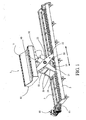
- the scissor lift table 1, 1 ' is intended to raise and / or lower loads, especially in a horizontal plane, for example to load and / or unload a reel (not shown) .
- this lifting table 1, 1 ' has the advantage of being movable in translation in guide rails fixed to the ground to feed a reel or the like, which can be fixed or movable.
- the lifting table 1, 1 ' comprises a load-bearing platform 10 supported by two identical scissors 20, arranged parallel on either side of the plate 10.
- the load-carrying tray 10 may comprise a surface upper 11 plane, vee as in the examples illustrated, cylindrical, perforated or any other suitable form.
- Each chisel 20 consists of a pair of legs 21, 22 hinged at their intersection point called hinge 23.
- this hinge 23 coincides with the center of the legs 21, 22 so that the chisel 20 is perfectly symmetrical with respect to the two orthogonal axes passing through the articulation 23.
- this joint can also be distinct from the center of the legs of the chisel, the chisel then being symmetrical with respect to a single axis.
- each chisel 20 form four movable support points and are equipped with rollers 24 or the like, able to circulate respectively in upper rails 6 secured to the load bearing plate 10 and in the lower rails 5 fixed on the ground or on a frame or other.
- the lower rails 5 form guide rails in translation of the lifting table 1, 1 ', their length being determined according to the path to be traveled by said lifting table 1, 1'.
- the lifting table 1, 1 ' comprises at least a first actuator 30, 30' for moving the load bearing plate 10 vertically between a low position (cf. Fig. 3 , 6 ) and a high position (see other figures) and vice versa.
- the actuator 30 is arranged vertically in the axis of symmetry A of the lifting table 1, perpendicular to the load bearing plate 10, passing through the hinge 23 of the chisel 20. It extends between this hinge 23 and the door plate load 10 directly to the load, so that it has no direct effect on the lower rails 5 and the thrust force has only a vertical component.
- the lower rails 5 are not subjected to any bending stress that may create linearity defects and can thus serve as guide rails for moving in translation the mobile lifting table 1.
- the thrust force generated is always equal to that of the force developed by the actuator 30 divided by two, this ratio of 1 ⁇ 2 being fixed regardless of the level of elevation of the carrier plate load 10.
- this 1 ⁇ 2 ratio differs according to the position of the hinge 23 of the chisel 20.
- the stroke of the actuator 30 generates a reduced stroke of the load carrying tray 10.
- the coefficient of This actuator 30 is preferably constituted by a cylinder with single or double effect, hydraulic, pneumatic, electric, electromagnetic, but can be constituted by any other type of equivalent actuator. It may advantageously consist of a pneumo-hydraulic jack commonly used in garages, using compressed air present in all factories, of robust and reliable construction, and available as a standard piece in commerce, and therefore economically profitable.
- This jack may comprise a single rod or a telescopic rod 31 with two or more stages.
- a telescopic rod 31 significantly reduces the size of the cylinder to achieve a low dead point very low when the lift table 1 is in the low position.
- the body 32 of this jack is mounted on a yoke 33 disposed between the two scissors 20 and fixed to the hinge 23.
- the end of the telescopic rod 31 is fixed to the load plate 10 by any known means.
- the reverse configuration is possible, ie the cylinder body can be in direct support on the load bearing plate and the cylinder rod can be coupled to the chisel joint.
- the lifting table 1 comprises two first parallel actuators 30', distinct from the axis of symmetry A, arranged between the two scissors 20 and extending between the two legs 21, 22 of the chisel 20. They extend more precisely between the lower end of a first leg 22 and a fulcrum of the second leg 21 located above the hinge 23.
- the actuators 30 ' have no direct effect on the lower rails 5 and do not generate any bending stress likely to create linearity defects, so that these lower rails 5 may as for the previous example serve as guide rails for translational movement of the mobile lifting table 1 '.
- the lifting table 1, 1 ' is completed by at least one centering rod 40, 50 articulated between the chisel 20 and the load plate 10 so that the latter remains centered on the axis of symmetry A of the table during its vertical movements .
- the lifting table 1, 1 ' comprises a first centering rod 40 extending between a hinge point 41 connected to the leg 21 of the chisel 20 and a high point 42 connected to the load bearing plate 10 and a second centering rod 50 extending between a hinge point 51 connected to the other leg 22 of the chisel 20 and a low point 52 connected to the lower rails 5.
- the centering links 40, 50 have a length equal to one quarter of the length of the legs 21, 22 of the chisel 20, the hinge points 41, 51 are placed in the middle of the relevant section of each leg 21, 22 and the high points 42 and bottom 52 are aligned with the articulation 23 of the chisel 20 and coincides with the axis of symmetry A.
- the lifting table 1, 1 ' is movable in guide rails constituted by said lower rails 5 of the table and comprises for this purpose at least one second actuator 60, 60' couple with the chisel 20 to move said table horizontally from right to left and vice versa.
- the lower rails 5 preferably have a C shape to define a secure raceway, anti-crush for the feet of the operator, anti-derailment and anti-tilt.
- the low point 52 of the second links 50 comprises at least one rolling roller 54 or the like, flowing in the lower rails 5, these rollers 54 being mounted on the same axle shaft 55.
- the actuator 60 which may be an electric, pneumatic, hydraulic or similar motor, is attached to one end of the lower rails 5 and is arranged to pull and push the axle shaft 55 by via a first transmission 61 to chain, cable, belt, screw-nut or the like, and translate the load bearing plate 10 in both directions.
- a hydraulic cylinder, pneumatic or similar fixed to the ground and in direct engagement with the axle shaft 55, can provide this function.
- the first actuator 30 can be easily housed under the load-carrying tray 10, since the second actuator 60 is dissociated from the lifting table 1.
- the actuator 60 ' which can be an electric, pneumatic, hydraulic or similar motor, is embedded on the chisel 20, carried by a chair 56 connected to the axle 55 and provided with wheels 57 flowing in the lower rails 5.
- This actuator 60 ' is coupled to the lower rails 5 by a second transmission, such as a pinion (not visible) meshing with a rack 58 fixed to the ground between the lower rails 5, or by any equivalent means.
- a second transmission such as a pinion (not visible) meshing with a rack 58 fixed to the ground between the lower rails 5, or by any equivalent means.
- the stroke of the lifting table 1 ' can be increased without limit, unlike the first embodiment.
- the first actuators 30 ' must be offset with respect to the axis of symmetry A of the table 1 'as the second actuator 60' is housed between the scissors 20 under the load plate 10.
- the point of application of the traction or thrust force is always located in the axis of symmetry A of the table passing through the hinge 23 of the scissors 20, whatever the level of elevation. Therefore, the second actuator 60, 60 'has no effect on the vertical position of the chisel 20 and the axle shaft 55 and its rollers 54 are not carrying, the load being fully supported by the rollers rolling 24 scissors 20.
- the lifting table 1, 1 ' according to the invention can be made cheaply due to the small amount of components, some of which are very simple to achieve in particular by oxycutting, low assembly time and some standard parts of the trade as per for example the actuators 30, 30 ', 60, 60'. It is of course possible to achieve a lifting table with two or more superimposed scissors, depending on the loading height, using the same technology.
- This lifting table is made mobile in horizontal translation very simply and safely, with no difference in level with existing reels and other machines arranged upstream and downstream.
Claims (14)
- Hubtisch (1,1') mit einem Scherenelement, der eine Lastenträgerplatte (10) aufweist, die mittels mindestens einem Scherenelement (20) getragen ist, welches aus einem Paar von Schenkeln (21,22) ausgebildet ist, die an ihrem Schnittpunkt (23) gelenkig gelagert und mit vier beweglichen Drehpunkten (24) versehen sind, die jeweils in oberen Schienen (6), die mit der Lastenträgerplatte (10) verbunden sind, und in unteren Schienen (5) umlaufen, die mit dem Boden oder mit einem Fahrgestell verbunden sind, und mit mindestens einem ersten Stellglied (30), welches mit dem Scherenelement (20) verbunden ist, um die Lastenträgerplatte (10) vertikal zwischen einer niedrigen Position und einer hohen Position zu verlagern, dadurch gekennzeichnet, dass er mindestens ein zweites Stellglied (60,60') aufweist, welches mit dem Scherenelement (20) verbunden ist, um den Hubtisch (1,1') horizontal in Führungsschienen zu verlagern, die durch die unteren Schienen (5) ausgebildet sind, worin die entsprechenden beweglichen Drehpunkte des Scherenelementes (20) umlaufen.
- Hubtisch nach Anspruch 1, dadurch gekennzeichnet, dass das zweite Stellglied (60) feststehend, am Ende der unteren Schienen (5) positioniert und mit dem Scherenelement (20) durch ein erstes Übertragungselement (61) verbunden ist.
- Hubtisch nach Anspruch 1, dadurch gekennzeichnet, dass sich das zweite Stellglied (60') auf dem Scherenelement (20) befindet und mit den unteren Schienen (5) durch ein zweites Übertragungselement (58) verbunden ist.
- Hubtisch nach einem der Ansprüche 2 oder 3, dadurch gekennzeichnet, dass der Eintragungspunkt der Zug- oder Schubkraft des zweiten Stellgliedes (60,60') in der Symmetrieachse (A) des Hubtisches (1,1') angeordnet ist, wobei die Achse durch das Gelenk (23) des Scherenelementes (20) hindurch verläuft.
- Hubtisch nach Anspruch 1, dadurch gekennzeichnet, dass er mindestens eine erste Zentrierungspleuelstange (40), die zwischen einem der Schenkel (21) des Scherenelementes (20) und einem hohen Punkt (42) angebracht ist, der mit der Lastenträgerplatte (10) verbunden ist, und mindestens eine zweite Zentrierungspleuelstange (50) aufweist, die zwischen dem anderen Schenkel (22) des Scherenelementes (20) und einem niedrigen Punkt (52) angebracht ist, der in den unteren Schienen (5) umläuft.
- Hubtisch nach Anspruch 5, dadurch gekennzeichnet, dass die ersten und zweiten Zentrierungspleuelstangen (40,50) eine Länge gleich einem Viertel der Länge der Schenkel (21,22) des Scherenelementes (20) aufweisen, und dass die hohen (42) und niedrigen Punkte (52) mit der durch das Gelenk (23) des Scherenelementes (20) hindurchgehenden Symmetrieachse (A) ausgerichtet und zusammengelegt sind.
- Hubtisch nach Anspruch 1, dadurch gekennzeichnet, dass das erste Stellglied (30) in der Symmetrieachse (A) des Hubtisches (1) angeordnet ist, die durch das Gelenk (23) des Scherenelementes (20) hindurch verläuft und sich von dem Gelenk (23) zu der Lastenträgerplatte (10) derart erstreckt, dass ein zuvor festgelegter Weg des Stellgliedes (30) einen vervielfachten Weg der Lastenträgerplatte (10) erzeugt.
- Hubtisch nach Anspruch 7, dadurch gekennzeichnet, dass das Gelenk (23) des Scherenelementes (20) im Mittelpunkt der Schenkel (21,22) derart angeordnet ist, dass der zuvor festgelegte Weg des Stellgliedes (30) einen mit zwei multiplizierten Weg der Lastenträgerplatte (10) erzeugt.
- Hubtisch nach Anspruch 1, dadurch gekennzeichnet, dass das erste Stellglied (30) von der Symmetrieachse (A) des Hubtisches (1) getrennt ist, die durch das Gelenk (23) des Scherenelementes (20) hindurch verläuft, und sich zwischen den zwei Schenkeln (21,22) des Scherenelementes (20) erstreckt.
- Hubtisch nach einem der Ansprüche 7 bis 9, dadurch gekennzeichnet, dass das Stellglied (30) einen Zylinder aufweist.
- Hubtisch nach Anspruch 10, dadurch gekennzeichnet, dass der Zylinder eine Teleskopstange (31) aufweist.
- Hubtisch nach einem der vorangegangenen Ansprüche, dadurch gekennzeichnet, dass er zwei identische und parallele Scherenelemente (20) aufweist, wobei das erste Stellglied (30) zwischen den Scherenelementen (20) aufgenommen ist.
- Hubtisch nach Anspruch 12, dadurch gekennzeichnet, dass das erste Stellglied (30) von einem an dem Gelenk (23) des Scherenelementes (20) befestigten Bügel (33) getragen ist.
- Hubtisch nach Anspruch 12, dadurch gekennzeichnet, dass jedes Scherenelement (20) mit einem Paar von Zentrierungspleuelstangen (40,50) verbunden ist, und dass die unteren Punkte (52) der zweiten Zentrierungspleuelstangen (50) auf einer selben Achswelle (55) gelagert sind, die mit dem zweiten Stellglied (60,60') verbunden ist.
Applications Claiming Priority (1)
| Application Number | Priority Date | Filing Date | Title |
|---|---|---|---|
| FR0609206A FR2907441B1 (fr) | 2006-10-20 | 2006-10-20 | Table elevatrice a ciseau. |
Publications (3)
| Publication Number | Publication Date |
|---|---|
| EP1914193A1 EP1914193A1 (de) | 2008-04-23 |
| EP1914193A8 EP1914193A8 (de) | 2008-06-25 |
| EP1914193B1 true EP1914193B1 (de) | 2010-01-13 |
Family
ID=38055170
Family Applications (1)
| Application Number | Title | Priority Date | Filing Date |
|---|---|---|---|
| EP20070360052 Expired - Fee Related EP1914193B1 (de) | 2006-10-20 | 2007-10-18 | Scherenhebebühne |
Country Status (3)
| Country | Link |
|---|---|
| EP (1) | EP1914193B1 (de) |
| DE (1) | DE602007004274D1 (de) |
| FR (1) | FR2907441B1 (de) |
Families Citing this family (8)
| Publication number | Priority date | Publication date | Assignee | Title |
|---|---|---|---|---|
| DE102010012893A1 (de) * | 2010-03-26 | 2011-09-29 | Loesche Gmbh | Rollenmühle |
| US9522625B2 (en) | 2014-05-30 | 2016-12-20 | Troy A. Myers | Boat loading allignment device and method |
| CN104310009B (zh) * | 2014-10-10 | 2016-09-07 | 广东嘉腾机器人自动化有限公司 | 一种上下料机构 |
| CA2925376A1 (en) | 2015-04-01 | 2016-10-01 | Timothy Hing-Yan Chung | Portable height-adjustable tabletop assembly and method of adjusting a height of the same |
| CN106744473A (zh) * | 2016-09-27 | 2017-05-31 | 王俊峰 | 一种可升降式葛根切片机用移动装置 |
| CN111232870B (zh) * | 2018-11-29 | 2022-03-18 | 比亚迪股份有限公司 | 用于充电系统的升降平台及充电系统 |
| CN112607646A (zh) * | 2020-12-14 | 2021-04-06 | 温州竺陌机械科技有限公司 | 可替换接触部件的千斤顶 |
| CN112607647A (zh) * | 2020-12-14 | 2021-04-06 | 温州竺陌机械科技有限公司 | 带有辅助支脚的千斤顶 |
Family Cites Families (15)
| Publication number | Priority date | Publication date | Assignee | Title |
|---|---|---|---|---|
| GB326362A (en) | 1929-03-20 | 1930-03-13 | Scoffin And Willmott Ltd | Improvements in or relating to folding tables |
| GB878714A (en) * | 1958-06-16 | 1961-10-04 | Amalgamated Dental Co Ltd | Hoist |
| US3240529A (en) * | 1964-09-02 | 1966-03-15 | Amalgamated Dental Co Ltd | Hoist |
| BE791776A (fr) * | 1972-02-24 | 1973-03-16 | Trepel Ag | Table relevable a parallelogramme deformable |
| GB1502778A (en) | 1974-12-10 | 1978-03-01 | Rogers D | Scissor lift mechanism with actuating device |
| CH619671A5 (en) * | 1977-04-29 | 1980-10-15 | Geilinger Ag Metallbau | Push lifting platform |
| JPS54100050A (en) * | 1978-01-24 | 1979-08-07 | Masao Akimoto | Lifter with auxiliary link |
| US4194723A (en) * | 1978-04-14 | 1980-03-25 | Jlg Industries, Inc. | Scissors linkage workman's platform |
| US4943204A (en) * | 1988-11-30 | 1990-07-24 | Ehrlich Rodney P | Drop frame trailer construction |
| US5339749A (en) * | 1992-06-23 | 1994-08-23 | Hihasuto Seiko Co., Ltd. | Table positioning mechanism |
| GB2301282B (en) | 1992-09-24 | 1997-04-09 | Snell Elizabeth | Improvements relating to surgical tables |
| JPH09323896A (ja) * | 1996-04-05 | 1997-12-16 | Thk Kk | テーブル昇降装置 |
| JP2003081582A (ja) * | 2001-09-13 | 2003-03-19 | Hitachi Constr Mach Co Ltd | 作業機用作業台とその使用方法 |
| GB2386062B (en) * | 2002-03-07 | 2004-04-28 | Huntleigh Technology Plc | Adjustable bed |
| JP4433941B2 (ja) * | 2004-08-26 | 2010-03-17 | 株式会社ダイフク | 搬送装置 |
-
2006
- 2006-10-20 FR FR0609206A patent/FR2907441B1/fr not_active Expired - Fee Related
-
2007
- 2007-10-18 EP EP20070360052 patent/EP1914193B1/de not_active Expired - Fee Related
- 2007-10-18 DE DE200760004274 patent/DE602007004274D1/de active Active
Also Published As
| Publication number | Publication date |
|---|---|
| EP1914193A1 (de) | 2008-04-23 |
| FR2907441A1 (fr) | 2008-04-25 |
| EP1914193A8 (de) | 2008-06-25 |
| DE602007004274D1 (de) | 2010-03-04 |
| FR2907441B1 (fr) | 2009-06-12 |
Similar Documents
| Publication | Publication Date | Title |
|---|---|---|
| EP1914193B1 (de) | Scherenhebebühne | |
| EP1742858B1 (de) | Anlage und verfahren zur übertragung einer last zwischen einer transferplattform und einem transportfahrzeug | |
| EP0739286B1 (de) | Selbstlenkungsarm eines strassenfahrzeugs entlang einer leitschiene | |
| EP0100926B1 (de) | Fahrzeug zur Handhabung von Materialien mit orientierbarem Ausleger und eingebautem Stabilisiergestell | |
| EP2001710B1 (de) | Hubfahrzeug für in grossen höhen arbeitende personen | |
| EP2109575B1 (de) | Vorrichtung zur lagerung von objekten auf einer mobilen palette | |
| EP0001364A1 (de) | Einrichtung zum Senken oder Heben der oberen Ladefläche eines Wagentransportfahrzeuges | |
| FR2747381A1 (fr) | Dispositif de transfert d'une charge par poussee et traction dans un meme plan | |
| FR2597450A2 (fr) | Installation pour l'assemblage et/ou l'usinage de pieces portees par des palettes et palette faisant partie de cette installation | |
| EP0757132B9 (de) | Brückenteil, insbesondere zur Überwindung von Gräben durch Fahrzeuge und System zum transportieren und ablegen von solchen Brückenteilen | |
| FR2897049A1 (fr) | Table elevatrice a pietements articules. | |
| EP1923335A1 (de) | Anlage zur Beförderung einer Ladung auf parallelen Laufbändern | |
| EP0636448B1 (de) | Genaue Indexierungseinheit für eine Palette gegenüber einer Bearbeitungsstation | |
| EP3949925B1 (de) | Abnehmbares elektrisches antriebssystem für ein rollendes objekt, gleichzeitiges und kombiniertes greifen und entfernen der räder in längsrichtung | |
| FR2908399A1 (fr) | Tour de stockage. | |
| FR3110888A1 (fr) | Système de propulsion électrique amovible pour un objet roulant avec un moyen de préhension et de levage combinés et simultanés | |
| FR2878490A1 (fr) | Charuit elevateur a partie de charge relevable | |
| FR2816490A1 (fr) | Table elevatrice en ciseau a plateau centre | |
| FR3133386A1 (fr) | Dispositif transfert a convoyeurs transversaux imbriques | |
| BE664865A (de) | ||
| FR2741331A1 (fr) | Dispositif de bras extensible pour le deplacement horizontal de charges | |
| FR2487243A1 (fr) | Appareil pour l'execution de coupes dans des corps en matiere a l'etat sensiblement plastique, notamment des blocs non durcis | |
| FR2600994A1 (fr) | Portique pour chariots elevateurs | |
| WO2018020183A1 (fr) | Système élévateur permettant de monter ou descendre une plateforme | |
| EP1849720A1 (de) | Mobile vertikale Speichervorrichtung |
Legal Events
| Date | Code | Title | Description |
|---|---|---|---|
| PUAI | Public reference made under article 153(3) epc to a published international application that has entered the european phase |
Free format text: ORIGINAL CODE: 0009012 |
|
| AK | Designated contracting states |
Kind code of ref document: A1 Designated state(s): AT BE BG CH CY CZ DE DK EE ES FI FR GB GR HU IE IS IT LI LT LU LV MC MT NL PL PT RO SE SI SK TR |
|
| AX | Request for extension of the european patent |
Extension state: AL BA HR MK RS |
|
| 17P | Request for examination filed |
Effective date: 20081021 |
|
| AKX | Designation fees paid |
Designated state(s): DE FR IT |
|
| 17Q | First examination report despatched |
Effective date: 20081218 |
|
| GRAP | Despatch of communication of intention to grant a patent |
Free format text: ORIGINAL CODE: EPIDOSNIGR1 |
|
| GRAS | Grant fee paid |
Free format text: ORIGINAL CODE: EPIDOSNIGR3 |
|
| GRAA | (expected) grant |
Free format text: ORIGINAL CODE: 0009210 |
|
| AK | Designated contracting states |
Kind code of ref document: B1 Designated state(s): DE FR IT |
|
| REF | Corresponds to: |
Ref document number: 602007004274 Country of ref document: DE Date of ref document: 20100304 Kind code of ref document: P |
|
| PLBE | No opposition filed within time limit |
Free format text: ORIGINAL CODE: 0009261 |
|
| STAA | Information on the status of an ep patent application or granted ep patent |
Free format text: STATUS: NO OPPOSITION FILED WITHIN TIME LIMIT |
|
| 26N | No opposition filed |
Effective date: 20101014 |
|
| PG25 | Lapsed in a contracting state [announced via postgrant information from national office to epo] |
Ref country code: IT Free format text: LAPSE BECAUSE OF NON-PAYMENT OF DUE FEES Effective date: 20101018 |
|
| PGFP | Annual fee paid to national office [announced via postgrant information from national office to epo] |
Ref country code: DE Payment date: 20121026 Year of fee payment: 6 Ref country code: FR Payment date: 20121129 Year of fee payment: 6 |
|
| PGFP | Annual fee paid to national office [announced via postgrant information from national office to epo] |
Ref country code: IT Payment date: 20121024 Year of fee payment: 6 |
|
| REG | Reference to a national code |
Ref country code: DE Ref legal event code: R119 Ref document number: 602007004274 Country of ref document: DE Effective date: 20140501 |
|
| REG | Reference to a national code |
Ref country code: FR Ref legal event code: ST Effective date: 20140630 |
|
| PG25 | Lapsed in a contracting state [announced via postgrant information from national office to epo] |
Ref country code: IT Free format text: LAPSE BECAUSE OF NON-PAYMENT OF DUE FEES Effective date: 20131018 Ref country code: DE Free format text: LAPSE BECAUSE OF NON-PAYMENT OF DUE FEES Effective date: 20140501 Ref country code: FR Free format text: LAPSE BECAUSE OF NON-PAYMENT OF DUE FEES Effective date: 20131031 |