EP1911571A1 - Procédé de fabrication de pneumatique - Google Patents
Procédé de fabrication de pneumatique Download PDFInfo
- Publication number
- EP1911571A1 EP1911571A1 EP07019480A EP07019480A EP1911571A1 EP 1911571 A1 EP1911571 A1 EP 1911571A1 EP 07019480 A EP07019480 A EP 07019480A EP 07019480 A EP07019480 A EP 07019480A EP 1911571 A1 EP1911571 A1 EP 1911571A1
- Authority
- EP
- European Patent Office
- Prior art keywords
- tire
- raw
- groove
- supporting wall
- core
- Prior art date
- Legal status (The legal status is an assumption and is not a legal conclusion. Google has not performed a legal analysis and makes no representation as to the accuracy of the status listed.)
- Granted
Links
Images


Classifications
-
- B—PERFORMING OPERATIONS; TRANSPORTING
- B60—VEHICLES IN GENERAL
- B60C—VEHICLE TYRES; TYRE INFLATION; TYRE CHANGING; CONNECTING VALVES TO INFLATABLE ELASTIC BODIES IN GENERAL; DEVICES OR ARRANGEMENTS RELATED TO TYRES
- B60C19/00—Tyre parts or constructions not otherwise provided for
- B60C19/002—Noise damping elements provided in the tyre structure or attached thereto, e.g. in the tyre interior
-
- B—PERFORMING OPERATIONS; TRANSPORTING
- B29—WORKING OF PLASTICS; WORKING OF SUBSTANCES IN A PLASTIC STATE IN GENERAL
- B29D—PRODUCING PARTICULAR ARTICLES FROM PLASTICS OR FROM SUBSTANCES IN A PLASTIC STATE
- B29D30/00—Producing pneumatic or solid tyres or parts thereof
- B29D30/06—Pneumatic tyres or parts thereof (e.g. produced by casting, moulding, compression moulding, injection moulding, centrifugal casting)
- B29D30/0601—Vulcanising tyres; Vulcanising presses for tyres
- B29D30/0661—Rigid cores therefor, e.g. annular or substantially toroidal cores
-
- B—PERFORMING OPERATIONS; TRANSPORTING
- B29—WORKING OF PLASTICS; WORKING OF SUBSTANCES IN A PLASTIC STATE IN GENERAL
- B29D—PRODUCING PARTICULAR ARTICLES FROM PLASTICS OR FROM SUBSTANCES IN A PLASTIC STATE
- B29D30/00—Producing pneumatic or solid tyres or parts thereof
- B29D30/06—Pneumatic tyres or parts thereof (e.g. produced by casting, moulding, compression moulding, injection moulding, centrifugal casting)
- B29D30/0601—Vulcanising tyres; Vulcanising presses for tyres
- B29D30/0662—Accessories, details or auxiliary operations
-
- B—PERFORMING OPERATIONS; TRANSPORTING
- B29—WORKING OF PLASTICS; WORKING OF SUBSTANCES IN A PLASTIC STATE IN GENERAL
- B29D—PRODUCING PARTICULAR ARTICLES FROM PLASTICS OR FROM SUBSTANCES IN A PLASTIC STATE
- B29D30/00—Producing pneumatic or solid tyres or parts thereof
- B29D30/06—Pneumatic tyres or parts thereof (e.g. produced by casting, moulding, compression moulding, injection moulding, centrifugal casting)
- B29D30/08—Building tyres
- B29D30/10—Building tyres on round cores, i.e. the shape of the core is approximately identical with the shape of the completed tyre
- B29D30/12—Cores
-
- B—PERFORMING OPERATIONS; TRANSPORTING
- B60—VEHICLES IN GENERAL
- B60C—VEHICLE TYRES; TYRE INFLATION; TYRE CHANGING; CONNECTING VALVES TO INFLATABLE ELASTIC BODIES IN GENERAL; DEVICES OR ARRANGEMENTS RELATED TO TYRES
- B60C5/00—Inflatable pneumatic tyres or inner tubes
- B60C5/002—Inflatable pneumatic tyres or inner tubes filled at least partially with foam material
-
- Y—GENERAL TAGGING OF NEW TECHNOLOGICAL DEVELOPMENTS; GENERAL TAGGING OF CROSS-SECTIONAL TECHNOLOGIES SPANNING OVER SEVERAL SECTIONS OF THE IPC; TECHNICAL SUBJECTS COVERED BY FORMER USPC CROSS-REFERENCE ART COLLECTIONS [XRACs] AND DIGESTS
- Y10—TECHNICAL SUBJECTS COVERED BY FORMER USPC
- Y10T—TECHNICAL SUBJECTS COVERED BY FORMER US CLASSIFICATION
- Y10T152/00—Resilient tires and wheels
- Y10T152/10—Tires, resilient
- Y10T152/10495—Pneumatic tire or inner tube
Definitions
- the present invention relates to a method for manufacturing a pneumatic tire provided on the radially inside of the tread portion with a noise damper, more particularly to a technique for molding the noise damper during vulcanizing the tire.
- Pneumatic tires provided on the radially inside of the tread portion with a noise damper made of foamed material has been proposed in order to damp resonance of air in the annular tire cavity.
- tire noise during running can be reduced.
- a method for manufacturing a pneumatic tire of this kind wherein an expandable material for the noise damper is applied to the inner surface of an unvulcanized tire; the unvulcanized tire is put in a mold; an inflatable bladder is set in the tire hollow; and the bladder is inflated during heating the tire to thereby mold and vulcanize the tire and at the same time expand the expandable damper material.
- the inflated bladder presses the expandable damper material. Further, irrespective of partially or wholly, the tire is pressed onto the inside of the mold indirectly through the expandable material. Thus, it is very difficult to achieve dimensionally accurate, sufficient foaming of the expandable material and accurate molding of the tire at the same time.
- an object of the present invention to provide a method for manufacturing a pneumatic tire, by which an expandable damper material can expand accurately and sufficiently, and accordingly an effective noise damper can be formed and at the same time the tire can be molded accurately.
- a method for manufacturing a pneumatic tire with a noise damper comprises the steps of:
- the tire 1 comprises a tread portion 2, a pair of sidewall portions 3, a pair of bead portions 4 each with a bead core 5 therein, a carcass 6 extending between the bead portions 4, a belt 7 disposed radially outside the carcass 6 in the tread portion 2, and a noise damper 10 disposed radially inside the carcass 6 in the tread portion 2.
- the tire 1 is a radial tire for passenger cars.
- the carcass 6 comprises a ply 6A of radially arranged cords extending between the bead portions 4 through the tread portion 2 and sidewall portions 3, and turned up around the bead core 5 in each bead portion 4 from the inside to the outside of the tire.
- the belt comprises a breaker 7 and optionally a band disposed on the radially outside of the breaker 7.
- the breaker 7 comprises two cross plies 7A and 7B of parallel cords.
- the bead portions 4 are each provided with a bead apex 8 made of a hard rubber extending radially outwardly from the bead core 5 while tapering towards its radially outer end.
- An inner liner 11 made of an air-impermeable rubber is disposed on the inside of the carcass so as to extend over the almost entire inner surface of the carcass 6.
- the noise damper 10 in this example is disposed on the radially inside of the inner liner 11 in the tread portion 2.
- the noise damper 10 extends continuously in the tire circumferential direction, with a substantially constant cross sectional shape.
- the noise damper 10 may be formed discontinuously in the tire circumferential direction, namely, may be formed as circumferentially separated pieces.
- the cross sectional shape various shapes can be employed. But, preferably a low-aspect-ratio shape such that the maximum axial width is lager than the maximum radial thickness is employed.
- the noise damper 10 is disposed within the width Bw of the belt 7.
- a shape which is substantially symmetrical about the tire equatorial plane c is preferred. In this example, therefore, a flat symmetrical trapezoidal shape is used, which is centered on the tire equator, and of which axial width gradually decreases radially inwards.
- the noise damper 10 is made of a spongelike porous material of an open-cell type or a closed-cell type. Preferably, an open-cell type porous material is used.
- the volume of the noise damper 10 is preferably set in a range of from 1 to 20 % of the total volume of the tire cavity (i) defined by the tire and the wheel rim on which the tire is mounted.
- the tire 1 is manufactured as follows: a raw tire 30 is assembled by the use of a tire building core 12; the raw tire 30 assembled on the tire building core 12 is put in a mold M together with the tire building core 12; and the raw tire 30 is vulcanized.
- the tire building core 12 is a split core comprising:
- the outer ring 17 is made up of: inner sector pieces 17A positioned in the widthwise center of the outer ring 17; and outer sector pieces 17B disposed over the outside of the inner sector pieces 17A.
- the core 12 can be disassembled by:
- the outer sector pieces 17B are circumferentially arranged with no space therebetween and collectively form a molding face 18 and a pair of molding faces 19.
- the molding face 18 is for the tire inner surface 9 facing the tire cavity (i).
- the molding faces 19 are for the bottom surfaces of the bead portions 4.
- the molding faces 19 extend axially outwardly from the radially inner ends of the molding face 18.
- the molding face 18 is provided with at least one circumferential groove 20 within a part 18a for molding the inner surface 9a of the tread portion 2.
- the groove 20 has a cross sectional shape corresponding to that of the noise damper 10 to be molded and also has a corresponding length.
- the cross sectional shape is trapezoidal, and the groove 20 is circumferentially continuous.
- the above-mentioned tire components are assembled in their unvulcanized states(inclusive of semi-vulcanized states).
- raw bead base rubbers 4G1 forming the bead bottom surface are applied onto the molding faces 19; then a raw inner liner rubber 11G forming the inner liner 11 is applied onto the molding face 18; further the raw carcass ply 6A is applied to the outside of the these rubber components.
- an expandable material 10G forming the noise damper 10 is applied to the raw inner liner rubber 11G prior to the applying of the raw inner liner rubber 11G onto the molding face 18.
- the applied position of the expandable material 10G corresponds to that of the above-mentioned groove 20.
- the expandable material 10G various materials can be used insofar as they can expand by the heat during tire vulcanization. But, preferably used is a composition which comprises: at least one kind of polymer such as rubber, resin and elastomer; a blowing agent (or foaming agent) to cause foaming; a reinforcing agent if necessary; and additives.
- a composition which comprises: at least one kind of polymer such as rubber, resin and elastomer; a blowing agent (or foaming agent) to cause foaming; a reinforcing agent if necessary; and additives.
- the rubber polymer natural rubber, isoprene rubber, styrene butadiene rubber, butadiene rubber, chloroprene rubber, acrylonitrile-butadiene rubber, ethylene-propylene rubber and the like can be used alone or in combination.
- polyurethane polyethylene, epoxy resin, unsaturated polyester resin, vinylester resin, phenolic resin, nylon resin, polycarbonate resin and the like can be used alone or in combination.
- blowing agent various agents may be used insofar as they can causes foaming by the heat during vulcanization.
- ADCA azodicarbonamide
- DPT N,N'-dinitrosopentamethylenetetramine
- OBSH 4,4'-oxybis(benzenesulfonylhydrazide)
- the blowing agent is added together with a blowing aid and the like if necessary.
- the amount of the blowing agent is for example, not less than 2 PHR, preferably not less than 3 PHR, but preferably not more than 15 PHR, more preferably not more than 10 PHR.
- Figs.4(A) and 4(B) show an example of the raw carcass ply 6A.
- Figs.5(A) and 5(B) show another example of the raw carcass ply 6A.
- the raw carcass ply 6A is a strip 6S of rubberized carcass cords similar to that having been used in the conventional tire manufacturing methods. But, differently therefrom, the edges in the widthwise direction (b) are provided with cuts (e) at regular intervals. The cuts (e) are parallel with the embedded carcass cords and positioned between the carcass cords. The strip 6s is winded around the full circumference of the tire building core 12 as shown in Fig.4(B).
- the cuts (e) are utilized to prevent occurrence of wrinkles of the strip in the bead portions.
- the edges (s) of the portions circumferentially separated by the cuts are overlapped to absorb the difference in the winding diameter.
- the raw carcass ply 6A is made up of a large number of circumferentially separated pieces 6P in contrast to the above-mentioned partially continuous long strip 6S.
- the carcass cords are laid side by side in the direction (a) and extends in the direction (b).
- the pieces 6P are applied around the full circumference of the core 12 with no space therebetween.
- the edges of the pieces 6P can be overlapped in order to prevent occurrence of wrinkles.
- the raw carcass ply 6A is applied such that the edges thereof protrude both sides of the core 12.
- the annular raw bead cores 5 are disposed one on each side of the toroidal carcass ply main portion applied around the core 12 so that the carcass ply edges protrude through the bead cores 5.
- the raw bead apex rubbers 8G are applied.
- the protruding carcass ply edges are winded around the bead cores 5 on to the bead apex rubbers, respectively.
- axially outer raw bead rubbers 4G2, raw sidewall rubbers 3G, the raw belt 7, a raw tread rubber 2G and the like are applied onto the carcass ply 6A as shown in Fig.6.
- the raw tire 30 is formed on the tire building core 12.
- the raw tire 30 is, together with the core 12, put in a hollow cv of a vulcanizing mold M splitable radially and axially for example, and subsequently the vulcanizing step is carried out.
- the raw tire 30 is heated to plasticize the rubber portions of the raw tire 30 so as to be molded along the molding face 32 of the mold M and the molding faces 18 and 19 of the core 12, and also to vulcanize the rubber portions.
- the temperature of the mold M is raised. Further, it is possible to raise the temperature of the tire building core 12 to heat the raw tire 30 from the inside.
- the core 12 is formed of a metal material such as an aluminum alloy.
- the expanded material 10G (or noise damper 10) is united with the vulcanized inner liner rubber 11G (or inner liner 11).
- the tire 1 is removed from the vulcanizing mold M together with the core 12. Then, the core 12 is disassembled and removed from the vulcanized tire 1.
- the expanded damper material 10G highly likely becomes a closed-cell type at least at the surface although an open-cell type is preferred as explained above. Therefore, the following additional step (1) and/or (2) is preferably carried out after the vulcanizing step.
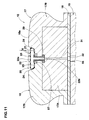
- Fig.10 shows a modification of the tire building core 12 shown in Fig.2, wherein the groove 20 is provided therein with a supporting wall 23 which can expand (Fig.11) or contract (Fig.12) in the radial direction to support the expandable damper material 10G.
- the supporting wall 23 is kept expanded as shown in Fig.13 to support the inner liner rubber 11G (the depth d thereof is substantially equal to or slightly smaller than the thickness of the material 10G). But during vulcanizing the tire, as shown in Fig.14, the supporting wall 23 is contracted so that the material 10G can expand sufficiently.
- the supporting wall 23 can be utilized to apply the expandable damper material 10G onto the inside of the inner liner rubber 11G as follows. Firstly, the expandable damper material 10G is applied to the supporting wall 23 expanded. Then, the inner liner rubber 11G is applied onto the molding face 18, covering over the expandable damper material 10G within the groove 20. Thereafter, the supporting wall 23 is preferably further expanded so as to press and thereby adhere the damper material 10G to the inside of the inner liner rubber 11G. when this further expansion is carried out, the depth d of the expanded supporting wall 23 may be slightly larger than the thickness of the material 10G. when not carried out, the depth is equal to or slightly smaller than the thickness.
- the supporting wall 23 is formed by an elastic membrane 22a.
- the elastic membrane 22a in this example is formed by a radially outer part of an inflatable elastic tube 22 disposed on the groove bottom.
- the radially inner part and lateral parts of the tube closely contact with the groove bottom 25 and groove side walls 24, respectively.
- the tube In the inflated state, the tube has a relatively flat cross sectional shape, and the radially outer part is almost flat.
- the radially inner part of the tube 22 is provided with a radially inwardly protruding pipe 22b of which radially outer end communicates with the inside of the tube 22.
- the pipe 22b is inserted into a stepped hole 27 provided in the groove bottom 25.
- the stepped hole 27 penetrates the outer sector pieces 17B and reaches to the inner sector piece 17A.
- the stepped hole 27 is continued to through holes 31, 32 and 33 provided in the inner sector pieces 17A, the middle ring 16 and the inner ring 15, respectively.
- the pressure controller P can feed the inside of the tube 22 with high-pressure air to expand the supporting wall 23. Further, the pressure controller P can discharge or pump out of the air in the tube to contract the supporting wall 23.
- gaskets 29 are provided where necessary.
- the groove 20 in order to form the circumferentially continuous noise damper 10, the groove 20 has to be continuous in the circumferential direction. Accordingly, the annular tube 22 is used. However, in the case of the discontinuous noise damper 10, the groove 20 is also discontinuous. Therefore, instead of the annular tube 22, relatively short bladders 22 each provided with the air pipe 22b connected with the air pressure controller P in the same manner as above can be used. In this case, it is further possible to modify the supporting wall 23 such that, instead of the bladders 22, the supporting wall 23 is formed by an actual elastic membrane of which peripheral edge is fixed airtightly to the surrounding groove wall over the entire length of the edge.
- a plurality of segments 40 made of a rigid material such as a metal and being movable radially inwardly and outwardly by an actuator (not shown) can be used as the supporting walls 23.
- a radial tire for passenger cars was manufactured as illustrated in Figs.3, 4(A), 4(B), 6, 7 and 8.
- Tire size 195/65R15 Carcass 6; a single ply of cords arranged radially at 90 degrees with respect to the tire equator Belt: two cross ply steel breaker Groove 20: Maximum width 6.0 cm Maximum depth 2.0 cm volume 2,170 cc
- Expandable damper material 10G Shape Circumferentially continuous strip Width 5.0 cm Thickness 1.0 cm Volume 945 cc Composition as follows Halogenated butyl rubber 50 phr NR/IR 35 phr BR 15 phr Carbon black 25 phr Mineral oil 14 phr Sulfur 0.6 phr Accelerator 1.8 phr Zinc oxide 4 phr Stearic acid 2 phr Tackifier resin 2 phr OBSH (blowing agent) *1 5 phr Urea
Applications Claiming Priority (1)
| Application Number | Priority Date | Filing Date | Title |
|---|---|---|---|
| JP2006277990A JP4891727B2 (ja) | 2006-10-11 | 2006-10-11 | 空気入りタイヤの製造方法 |
Publications (2)
| Publication Number | Publication Date |
|---|---|
| EP1911571A1 true EP1911571A1 (fr) | 2008-04-16 |
| EP1911571B1 EP1911571B1 (fr) | 2009-09-09 |
Family
ID=38822112
Family Applications (1)
| Application Number | Title | Priority Date | Filing Date |
|---|---|---|---|
| EP07019480A Active EP1911571B1 (fr) | 2006-10-11 | 2007-10-04 | Procédé de fabrication de pneumatique |
Country Status (5)
| Country | Link |
|---|---|
| US (1) | US7857926B2 (fr) |
| EP (1) | EP1911571B1 (fr) |
| JP (1) | JP4891727B2 (fr) |
| CN (1) | CN101161447B (fr) |
| DE (1) | DE602007002356D1 (fr) |
Cited By (4)
| Publication number | Priority date | Publication date | Assignee | Title |
|---|---|---|---|---|
| WO2011051203A1 (fr) * | 2009-10-27 | 2011-05-05 | Societe De Technologie Michelin | Bandage pneumatique dont la paroi interne est pourvue d'une couche de caoutchouc thermo-expansible |
| EP2349668A1 (fr) * | 2008-11-21 | 2011-08-03 | Société de Technologie MICHELIN | Appareil et procédé de polymérisation d'un article semblable à du caoutchouc |
| EP2457749A1 (fr) * | 2010-11-24 | 2012-05-30 | The Goodyear Tire & Rubber Company | Procédé de fabrication de pneu avec amortisseur de bruit en mousse et pneu |
| EP2433786A3 (fr) * | 2010-09-24 | 2013-07-31 | The Goodyear Tire & Rubber Company | Procédé de fabrication de pneu et pneu avec un amortisseur de bruit en mousse ou dispositif électronique |
Families Citing this family (19)
| Publication number | Priority date | Publication date | Assignee | Title |
|---|---|---|---|---|
| EP2093080B1 (fr) * | 2006-12-06 | 2011-12-21 | Bridgestone Corporation | Pneu et procédé de production de celui-ci |
| US8308368B2 (en) * | 2007-07-13 | 2012-11-13 | Rexnord Industries, Llc | Track roller |
| JP4263755B1 (ja) * | 2007-10-23 | 2009-05-13 | 住友ゴム工業株式会社 | 空気入りタイヤの製造方法 |
| US8109312B2 (en) * | 2007-12-29 | 2012-02-07 | Michelin Recherche Et Technique S.A. | Tire patch applicator |
| US20100071820A1 (en) * | 2008-09-24 | 2010-03-25 | Bridgestone Americas Tire Operations, Llc | Tire and noise reducer |
| JP2012507442A (ja) * | 2008-10-29 | 2012-03-29 | インターナショナル マーケティング インコーポレイテッド | タイヤ‐車輪アセンブリの圧力変化と振動を矯正するための構成 |
| JP5350876B2 (ja) * | 2009-05-07 | 2013-11-27 | 株式会社ブリヂストン | タイヤの製造方法 |
| JP4981849B2 (ja) * | 2009-06-12 | 2012-07-25 | 住友ゴム工業株式会社 | 空気入りタイヤ及びその製造方法 |
| JP5010017B2 (ja) * | 2010-08-10 | 2012-08-29 | 住友ゴム工業株式会社 | 空気入りタイヤの製造方法及び成形装置 |
| US8177538B1 (en) | 2011-03-21 | 2012-05-15 | Bridgestone Americas Tire Operations, Llc | Tire mold having sidewall structure |
| US9415553B2 (en) | 2011-05-04 | 2016-08-16 | Compagnie Generale Des Etablissements Michelin | Apparatus and method for curing a rubber like article |
| JP5952700B2 (ja) * | 2012-10-03 | 2016-07-13 | 住友ゴム工業株式会社 | 剛性中子及びそれを用いた空気入りタイヤの製造方法 |
| JP6400910B2 (ja) * | 2014-01-22 | 2018-10-03 | 住友ゴム工業株式会社 | 空気入りタイヤ |
| JP6444670B2 (ja) * | 2014-09-12 | 2018-12-26 | 株式会社ブリヂストン | 空気入りタイヤ及びその組立体 |
| IT201900001641A1 (it) * | 2019-02-05 | 2020-08-05 | Bridgestone Europe Nv Sa | Pneumatico comprendente uno strato sigillante e un elemento fonoassorbente |
| CN110423413A (zh) * | 2019-06-13 | 2019-11-08 | 万力轮胎股份有限公司 | 一种橡胶组合物及其制备方法与应用 |
| CN110450583A (zh) * | 2019-06-13 | 2019-11-15 | 万力轮胎股份有限公司 | 一种静音轮胎及其制备方法 |
| MX2022006559A (es) * | 2019-12-19 | 2022-06-29 | Michelin & Cie | Metodo de moldeo de un contenedor en un neumatico. |
| CN111332076A (zh) * | 2020-03-30 | 2020-06-26 | 正新橡胶(中国)有限公司 | 一种降噪轮胎及其制造工艺和一种车轮 |
Citations (6)
| Publication number | Priority date | Publication date | Assignee | Title |
|---|---|---|---|---|
| JPH01254411A (ja) * | 1988-04-01 | 1989-10-11 | Bridgestone Corp | 吸音層を有する空気入りタイヤの製造方法 |
| DE19806935A1 (de) * | 1998-02-19 | 1999-09-09 | Continental Ag | Verfahren zum Herstellen eines Fahrzeugluftreifens mit einer an seiner Innenseele anhaftenden schallabsorbierenden Schaumstoffschicht sowie gemäß diesem Verfahren hergestellter Reifen |
| EP1253025A2 (fr) * | 2001-04-16 | 2002-10-30 | Sumitomo Rubber Industries Ltd. | Système de réduction du bruit d'un bandage pneumatique |
| JP2003326915A (ja) * | 2002-05-16 | 2003-11-19 | Bridgestone Corp | 空気入りラジアルタイヤ |
| US20060185777A1 (en) * | 2003-08-04 | 2006-08-24 | Atsushi Tanno | Low noise pneumatic tire |
| EP1800911A2 (fr) * | 2005-12-20 | 2007-06-27 | The Goodyear Tire & Rubber Company | Pneumatique avec un amortisseur de bruit |
Family Cites Families (11)
| Publication number | Priority date | Publication date | Assignee | Title |
|---|---|---|---|---|
| CA2121159C (fr) * | 1993-07-16 | 2005-03-29 | Kenneth Dean Conger | Tambour de fabrication de pneus profiles et fabrication de pneus |
| US6113833A (en) * | 1997-07-22 | 2000-09-05 | Bridgestone Corporation | Segmented toroidal core for manufacturing pneumatic tires |
| US6223797B1 (en) * | 1998-01-29 | 2001-05-01 | The Yokohama Rubber Co. | Pneumatic tire with specified rubber properties |
| JP3974437B2 (ja) * | 2002-03-28 | 2007-09-12 | 住友ゴム工業株式会社 | 空気入りタイヤ |
| US20050133132A1 (en) * | 2003-12-23 | 2005-06-23 | Jean-Claude Girard | Apparatus and method for incorporating an annular antenna and electronics into a tire |
| JP4410570B2 (ja) * | 2004-01-21 | 2010-02-03 | 株式会社ブリヂストン | 空気入りタイヤの製造方法 |
| JP4224432B2 (ja) * | 2004-06-14 | 2009-02-12 | 住友ゴム工業株式会社 | 空気入りタイヤとリムとの組立体 |
| JP2006103106A (ja) * | 2004-10-04 | 2006-04-20 | Bridgestone Corp | タイヤ加硫成型金型 |
| US7389802B2 (en) * | 2004-12-30 | 2008-06-24 | The Goodyear Tire & Rubber Co. | Tire with double layer innerliner |
| JP2007331292A (ja) * | 2006-06-16 | 2007-12-27 | Bridgestone Corp | 空気入りタイヤの製造方法及び剛体コア |
| JP4843435B2 (ja) * | 2006-09-22 | 2011-12-21 | 住友ゴム工業株式会社 | 空気入りタイヤの製造方法 |
-
2006
- 2006-10-11 JP JP2006277990A patent/JP4891727B2/ja not_active Expired - Fee Related
-
2007
- 2007-10-04 DE DE602007002356T patent/DE602007002356D1/de active Active
- 2007-10-04 EP EP07019480A patent/EP1911571B1/fr active Active
- 2007-10-09 CN CN200710164305.6A patent/CN101161447B/zh not_active Expired - Fee Related
- 2007-10-10 US US11/907,266 patent/US7857926B2/en not_active Expired - Fee Related
Patent Citations (6)
| Publication number | Priority date | Publication date | Assignee | Title |
|---|---|---|---|---|
| JPH01254411A (ja) * | 1988-04-01 | 1989-10-11 | Bridgestone Corp | 吸音層を有する空気入りタイヤの製造方法 |
| DE19806935A1 (de) * | 1998-02-19 | 1999-09-09 | Continental Ag | Verfahren zum Herstellen eines Fahrzeugluftreifens mit einer an seiner Innenseele anhaftenden schallabsorbierenden Schaumstoffschicht sowie gemäß diesem Verfahren hergestellter Reifen |
| EP1253025A2 (fr) * | 2001-04-16 | 2002-10-30 | Sumitomo Rubber Industries Ltd. | Système de réduction du bruit d'un bandage pneumatique |
| JP2003326915A (ja) * | 2002-05-16 | 2003-11-19 | Bridgestone Corp | 空気入りラジアルタイヤ |
| US20060185777A1 (en) * | 2003-08-04 | 2006-08-24 | Atsushi Tanno | Low noise pneumatic tire |
| EP1800911A2 (fr) * | 2005-12-20 | 2007-06-27 | The Goodyear Tire & Rubber Company | Pneumatique avec un amortisseur de bruit |
Cited By (8)
| Publication number | Priority date | Publication date | Assignee | Title |
|---|---|---|---|---|
| EP2349668A1 (fr) * | 2008-11-21 | 2011-08-03 | Société de Technologie MICHELIN | Appareil et procédé de polymérisation d'un article semblable à du caoutchouc |
| EP2349668A4 (fr) * | 2008-11-21 | 2012-11-28 | Michelin & Cie | Appareil et procédé de polymérisation d'un article semblable à du caoutchouc |
| WO2011051203A1 (fr) * | 2009-10-27 | 2011-05-05 | Societe De Technologie Michelin | Bandage pneumatique dont la paroi interne est pourvue d'une couche de caoutchouc thermo-expansible |
| FR2952645A1 (fr) * | 2009-10-27 | 2011-05-20 | Michelin Soc Tech | Bandage pneumatique dont la paroi interne est pourvue d'une couche de caoutchouc thermo-expansible |
| US20120247637A1 (en) * | 2009-10-27 | 2012-10-04 | Michelin Recherche Et Technique S.A. | Tyre, the inner wall of which is provided with a heat-expandable rubber layer |
| US8978721B2 (en) | 2009-10-27 | 2015-03-17 | Compagnie Generale Des Etablissements Michelin | Tyre, the inner wall of which is provided with a heat-expandable rubber layer |
| EP2433786A3 (fr) * | 2010-09-24 | 2013-07-31 | The Goodyear Tire & Rubber Company | Procédé de fabrication de pneu et pneu avec un amortisseur de bruit en mousse ou dispositif électronique |
| EP2457749A1 (fr) * | 2010-11-24 | 2012-05-30 | The Goodyear Tire & Rubber Company | Procédé de fabrication de pneu avec amortisseur de bruit en mousse et pneu |
Also Published As
| Publication number | Publication date |
|---|---|
| EP1911571B1 (fr) | 2009-09-09 |
| US20080087368A1 (en) | 2008-04-17 |
| CN101161447A (zh) | 2008-04-16 |
| JP4891727B2 (ja) | 2012-03-07 |
| DE602007002356D1 (de) | 2009-10-22 |
| US7857926B2 (en) | 2010-12-28 |
| CN101161447B (zh) | 2012-08-29 |
| JP2008093953A (ja) | 2008-04-24 |
Similar Documents
| Publication | Publication Date | Title |
|---|---|---|
| EP1911571B1 (fr) | Procédé de fabrication de pneumatique | |
| US4249588A (en) | Pneumatic tire | |
| JP4900608B2 (ja) | タイヤ加硫用ブラダー、タイヤの加硫成形方法及び空気入りタイヤ | |
| EP1676722B1 (fr) | Pneumatique avec couche interne pour réduire le bruit, et une méthode pour le fabriquer. | |
| EP2433786A2 (fr) | Procédé de fabrication de pneu et pneu avec un amortisseur de bruit en mousse ou dispositif électronique | |
| KR20070065821A (ko) | 일체적 발포 소음 댐퍼를 갖는 타이어 | |
| EP2727713B1 (fr) | Procédé et appareil permettant d'appliquer une bande annulaire à l'intérieur d'un pneu | |
| US20070131326A1 (en) | Pneumatic tire and noise damper assembly | |
| US4722377A (en) | Tire safety support system | |
| US4418734A (en) | Safety support system | |
| EP2457749A1 (fr) | Procédé de fabrication de pneu avec amortisseur de bruit en mousse et pneu | |
| JP4843435B2 (ja) | 空気入りタイヤの製造方法 | |
| JP6035433B2 (ja) | タイヤ加硫用ブラダーの製造方法 | |
| US20080283166A1 (en) | Method for manufacturing pneumatic tire | |
| EP2440398B1 (fr) | Procédé de contrôle de l'évacuation de fluides au cours d'un processus de moulage et de vulcanisation d'un pneu cru et pneu pour roues de véhicule ainsi obtenu. | |
| US20210245556A1 (en) | Pneumatic tire | |
| US20130139938A1 (en) | Tire manufacturing method, tread member and tire | |
| EP1793980B1 (fr) | Procede et appareil de fabrication de pneus | |
| JP2009269235A (ja) | タイヤ加硫用ブラダー、タイヤの加硫成形方法及び空気入りタイヤ | |
| US4186042A (en) | Puncture sealing tire | |
| EP1629962A1 (fr) | Vessie de vulcanisation d'un pneu | |
| JP4191936B2 (ja) | 空気入りタイヤの製造方法、及び空気入りタイヤ | |
| EP0165202B1 (fr) | Procédé de fabrication d'un support de sécurité | |
| US8007710B2 (en) | Method and apparatus for manufacturing pneumatic tyres | |
| EP3730267A1 (fr) | Vessie pour vulcanisation de pneus et pneumatique |
Legal Events
| Date | Code | Title | Description |
|---|---|---|---|
| PUAI | Public reference made under article 153(3) epc to a published international application that has entered the european phase |
Free format text: ORIGINAL CODE: 0009012 |
|
| AK | Designated contracting states |
Kind code of ref document: A1 Designated state(s): AT BE BG CH CY CZ DE DK EE ES FI FR GB GR HU IE IS IT LI LT LU LV MC MT NL PL PT RO SE SI SK TR |
|
| AX | Request for extension of the european patent |
Extension state: AL BA HR MK RS |
|
| 17P | Request for examination filed |
Effective date: 20081002 |
|
| 17Q | First examination report despatched |
Effective date: 20081031 |
|
| AKX | Designation fees paid |
Designated state(s): DE FR |
|
| GRAP | Despatch of communication of intention to grant a patent |
Free format text: ORIGINAL CODE: EPIDOSNIGR1 |
|
| RIC1 | Information provided on ipc code assigned before grant |
Ipc: B60C 19/00 20060101ALI20090317BHEP Ipc: B29D 30/06 20060101ALI20090317BHEP Ipc: B29D 30/00 20060101AFI20090317BHEP Ipc: B60C 5/00 20060101ALI20090317BHEP Ipc: B29D 30/10 20060101ALI20090317BHEP |
|
| GRAS | Grant fee paid |
Free format text: ORIGINAL CODE: EPIDOSNIGR3 |
|
| GRAA | (expected) grant |
Free format text: ORIGINAL CODE: 0009210 |
|
| AK | Designated contracting states |
Kind code of ref document: B1 Designated state(s): DE FR |
|
| REF | Corresponds to: |
Ref document number: 602007002356 Country of ref document: DE Date of ref document: 20091022 Kind code of ref document: P |
|
| PLBE | No opposition filed within time limit |
Free format text: ORIGINAL CODE: 0009261 |
|
| STAA | Information on the status of an ep patent application or granted ep patent |
Free format text: STATUS: NO OPPOSITION FILED WITHIN TIME LIMIT |
|
| 26N | No opposition filed |
Effective date: 20100610 |
|
| PGFP | Annual fee paid to national office [announced via postgrant information from national office to epo] |
Ref country code: FR Payment date: 20131009 Year of fee payment: 7 |
|
| REG | Reference to a national code |
Ref country code: FR Ref legal event code: ST Effective date: 20150630 |
|
| PG25 | Lapsed in a contracting state [announced via postgrant information from national office to epo] |
Ref country code: FR Free format text: LAPSE BECAUSE OF NON-PAYMENT OF DUE FEES Effective date: 20141031 |
|
| PGFP | Annual fee paid to national office [announced via postgrant information from national office to epo] |
Ref country code: DE Payment date: 20220621 Year of fee payment: 16 |
|
| P01 | Opt-out of the competence of the unified patent court (upc) registered |
Effective date: 20230510 |