EP1908689A2 - Baguette de calfeutrage pour le contrôle de l'introduction de gaz dans les paquets - Google Patents
Baguette de calfeutrage pour le contrôle de l'introduction de gaz dans les paquets Download PDFInfo
- Publication number
- EP1908689A2 EP1908689A2 EP07019244A EP07019244A EP1908689A2 EP 1908689 A2 EP1908689 A2 EP 1908689A2 EP 07019244 A EP07019244 A EP 07019244A EP 07019244 A EP07019244 A EP 07019244A EP 1908689 A2 EP1908689 A2 EP 1908689A2
- Authority
- EP
- European Patent Office
- Prior art keywords
- packaging
- machine according
- sealing
- gas supply
- packaging machine
- Prior art date
- Legal status (The legal status is an assumption and is not a legal conclusion. Google has not performed a legal analysis and makes no representation as to the accuracy of the status listed.)
- Withdrawn
Links
Images


Classifications
-
- B—PERFORMING OPERATIONS; TRANSPORTING
- B65—CONVEYING; PACKING; STORING; HANDLING THIN OR FILAMENTARY MATERIAL
- B65B—MACHINES, APPARATUS OR DEVICES FOR, OR METHODS OF, PACKAGING ARTICLES OR MATERIALS; UNPACKING
- B65B31/00—Packaging articles or materials under special atmospheric or gaseous conditions; Adding propellants to aerosol containers
- B65B31/02—Filling, closing, or filling and closing, containers or wrappers in chambers maintained under vacuum or superatmospheric pressure or containing a special atmosphere, e.g. of inert gas
- B65B31/025—Filling, closing, or filling and closing, containers or wrappers in chambers maintained under vacuum or superatmospheric pressure or containing a special atmosphere, e.g. of inert gas specially adapted for rigid or semi-rigid containers
- B65B31/028—Filling, closing, or filling and closing, containers or wrappers in chambers maintained under vacuum or superatmospheric pressure or containing a special atmosphere, e.g. of inert gas specially adapted for rigid or semi-rigid containers closed by a lid sealed to the upper rim of the container, e.g. tray-like container
-
- B—PERFORMING OPERATIONS; TRANSPORTING
- B65—CONVEYING; PACKING; STORING; HANDLING THIN OR FILAMENTARY MATERIAL
- B65B—MACHINES, APPARATUS OR DEVICES FOR, OR METHODS OF, PACKAGING ARTICLES OR MATERIALS; UNPACKING
- B65B31/00—Packaging articles or materials under special atmospheric or gaseous conditions; Adding propellants to aerosol containers
- B65B31/04—Evacuating, pressurising or gasifying filled containers or wrappers by means of nozzles through which air or other gas, e.g. an inert gas, is withdrawn or supplied
- B65B31/06—Evacuating, pressurising or gasifying filled containers or wrappers by means of nozzles through which air or other gas, e.g. an inert gas, is withdrawn or supplied the nozzle being arranged for insertion into, and withdrawal from, the mouth of a filled container and operating in conjunction with means for sealing the container mouth
-
- B—PERFORMING OPERATIONS; TRANSPORTING
- B65—CONVEYING; PACKING; STORING; HANDLING THIN OR FILAMENTARY MATERIAL
- B65B—MACHINES, APPARATUS OR DEVICES FOR, OR METHODS OF, PACKAGING ARTICLES OR MATERIALS; UNPACKING
- B65B7/00—Closing containers or receptacles after filling
- B65B7/16—Closing semi-rigid or rigid containers or receptacles not deformed by, or not taking-up shape of, contents, e.g. boxes or cartons
- B65B7/162—Closing semi-rigid or rigid containers or receptacles not deformed by, or not taking-up shape of, contents, e.g. boxes or cartons by feeding web material to securing means
- B65B7/164—Securing by heat-sealing
-
- B—PERFORMING OPERATIONS; TRANSPORTING
- B65—CONVEYING; PACKING; STORING; HANDLING THIN OR FILAMENTARY MATERIAL
- B65B—MACHINES, APPARATUS OR DEVICES FOR, OR METHODS OF, PACKAGING ARTICLES OR MATERIALS; UNPACKING
- B65B31/00—Packaging articles or materials under special atmospheric or gaseous conditions; Adding propellants to aerosol containers
- B65B31/04—Evacuating, pressurising or gasifying filled containers or wrappers by means of nozzles through which air or other gas, e.g. an inert gas, is withdrawn or supplied
- B65B31/043—Evacuating, pressurising or gasifying filled containers or wrappers by means of nozzles through which air or other gas, e.g. an inert gas, is withdrawn or supplied the nozzles acting horizontally between an upper and a lower part of the container or wrapper, e.g. between container and lid
Definitions
- the invention relates to a packaging machine according to the preamble of claim 1.
- Packaging machines for packaging packaged goods in packaging are known in different designs. In the field of food packaging, machines are used in which the atmospheric air is sucked out of the filled packaging and then one or more gases are supplied to the packaging before the seal. Among other things, this evacuation and subsequent gas supply is important for the shelf life of the packaged products.
- the packages are evacuated in a vacuum chamber.
- the gas supply takes place via gas pipes, which are laid in the area of the packaging to be fumigated. Since the packages are not yet sealed in the fumigation, the supplied gas can get into the vacuum chamber or in the suction system of the machine on the same way as previously the residual atmosphere was evacuated. A controlled metered gassing of the packaging is not possible.
- the invention therefore has the task of proposing a packaging machine in which a controlled gas supply into the packaging is possible.
- the invention is characterized in that means are provided for closing the packages with respect to the suction means before the subsequent gas supply.
- the gas to be supplied can thus be supplied to the packaging in a controlled manner. There is an overall better dosage of the supplied gas and thus a better match on the packaged in the packaged packaged possible.
- a packaging machine In a packaging machine according to the invention several contiguous packages can be evacuated and fumigated simultaneously. In this case, it is not necessary for each individual packaging to be assigned a suction opening or a gas inlet opening. Rather, prior to sealing, several contiguous packages may also be evacuated via one or more common suction ports and gassed via one or more common gas supply lines.
- the invention is advantageously used in packages which are made of at least two films, for example an upper and a lower film.
- packaging machines are known under the terms thermoforming or roller machine as well as tray sealing machine (so-called "tray sealer").
- traysealers prefabricated individual trays are filled with packaged goods and then sealed in a sealing station with a top film, which also take place here suction and gassing before sealing.
- the packaging tray is usually also prefabricated from a film.
- a vacuum chamber Before aspirating the atmospheric air from the packages they are preferably placed in a vacuum chamber. This is closed in known embodiments in that two parts of the chamber joined together, for example, a lower part is raised against an upper part. The side bars of the packaging lie between the upper and lower part of the vacuum chamber. When compressing these two components thus upper and lower film are compressed, so that at least in the transverse direction relative to the feed direction, a correspondingly tight conclusion can take place.
- the packages can be evacuated by a negative pressure in the vacuum chamber, wherein the air flowing out of the packaging air emerges at the edge between lower film and upper film. In the case of a wider upper film, this can be compressed all around when the vacuum chamber is closed between its parts with the lower film.
- the air in the packages may pass through one or more openings in one or both foils e.g. be sucked off in an edge web of the lower film. These openings are preferably located in the edge region of the packaging or the arrangement of packaging in the case of several contiguous packaging.
- the flow path for the air to be extracted from the packaging can therefore be closed by using pressing elements which compress the two films.
- An escape of gas at the edge below the top film or through any suction openings in one or both films, e.g. the lower film, is thereby prevented, since these suction openings can be closed by compressing the films as well as the complete edge area. It is irrelevant whether such an opening is closed by the other film or directly by the pressing element.
- a pressing element for sealing the edge region of the packaging can in the region of the transverse webs (relative to the feed direction of the packaging in the packaging machine) by a transverse sealing strip be realized, which is advantageously formed as a functional unit with a wall of a part of the vacuum chamber.
- one or more gas supply lines In the longitudinal direction relative to the feed direction of the packages are usually one or more gas supply lines. These are preferably arranged to be placed between the films, e.g. between a top and a bottom foil. Since these gas supply lines are located in the interior of the vacuum chamber, there is the possibility, when the vacuum chamber is closed without sealing means according to the invention, that gas supplied into the packages can enter the vacuum chamber and thus the suction system of the machine.
- a seal of the interior of the packaging is sought.
- this is now preferably carried out with an additional pressing element such that the films, e.g. compress the top and bottom film.
- an additional pressing element such that the films, e.g. compress the top and bottom film.
- one or more sealing strips can be used, which extend in the longitudinal direction of the packaging or the arrangements or groups of packaging.
- the edge-side sealing means in particular in the form of sealing strips are preferably further developed such that they enclose the gas supply lines in a form-fitting manner.
- the films or one of the films, for example the top film, nestles between the sealing strips and the gas line to the shape of the Gas line on.
- the film is advantageously formed elastically.
- a deformable material for example an elastomer
- a sealing strip at least in the region of the gas supply lines.
- sealing strips can be made entirely of an elastomer in the region in which they press the films together. This material deforms during pressing in such a way that it snugly adapts to the gas supply lines and these are taken up in a sense in the sealing strip.
- the sealing of the packages can be carried out in a conventional manner by joining upper and lower sheets, for example by welding.
- a sealing tool such as a sealing plate or the like is preferably arranged within the sealing strips. This sealing tool is then able to connect the upper and lower film within the sealing strips on the edge webs, for example to weld.
- the peripheral edge is welded, which adjoins the inside directly to the sealing strip, which compress the upper and lower film.
- the marginal longitudinal webs are as in the case of individual packaging in the inside directly to the corresponding sealing strip subsequent area sealed.
- a controller for cyclically advancing individual packages or an arrangement of a plurality of contiguous packages causes a corresponding transport unit to advance the filled packages in the machine cycle in the lower part of the sealing station.
- the lower part is lowered at the sealing station.
- This lower part is then raised, so that the vacuum chamber is closed to suck the atmospheric air.
- the atmospheric air located in the packages can be sucked out via a suction pump together with the other, located in the vacuum chamber air.
- the air can escape in the transverse direction between upper and lower film from the packages, provided that the upper film is correspondingly narrow.
- suction openings e.g. be used in the lower film and an adjoining arrangement of suction lines to suck the residual atmosphere in the packaging.
- a correspondingly provided gas or a gas mixture can be supplied. This can be done with the help of the existing vacuum and or be accomplished by means of an external overpressure. Since the interior of the package are largely sealed to the outside, there is no connection between the interior of the packaging and the suction at the time of gas supply. Thus, among other things, a precise metering of the gas supplied is possible.
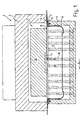
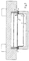
- the sealing station 1 shows a vacuum chamber 2, which is formed from a box-shaped upper part 3 and a likewise box-shaped lower part 4.
- a seal 5 is provided at the upper edge of the lower part 3 to seal the negative pressure chamber 2 in the closed position.
- Bottom sheet 6 formed shell is inserted into the lower part 4 of the vacuum chamber 2.
- the edge web 7 of the lower film extends between upper part 3 and lower part 4 beyond the vacuum chamber 2, since the lower film is continuously drawn off from a supply roll in the case of a deep-drawing or roller machine.
- the film with the shells formed therefrom thus extends in the longitudinal direction in one piece from the supply roll to a cutting station, not shown, behind the sealing station through the entire machine.
- An upper film 8 provided as a cover closes off the upper side of the lower film 6 and likewise extends with its edge 9 into the region of the edge web 7, since it is likewise drawn off from a supply roll in one piece.
- a in the longitudinal direction L relative to the feed direction of Foils extending in the packaging machine sealing strip 10 is disposed in the vacuum chamber 2 and provided with a lower recess 11.
- Suction lines 12 and gas supply lines 13 are indicated in Fig. 1 in order to illustrate their position in the longitudinal direction 11.
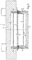
- FIG. 2 In the schematic cross-sectional view of FIG. 2, a section through a gas supply line 13 is shown on the right side. In this illustration, it can be seen that the gas supply line 13 is arranged in a side wall 14 of the lower part 4. A detail enlargement of the central region in which the sealing strip 10 according to the invention is arranged is shown in FIG. 4 and explained later.
- FIG. 2 On the left side of FIG. 2, a section through a suction line 12 is shown. Accordingly, the sealing strip 10 is cut here in a region located outside the recess 11 via a suction line 12. Furthermore, a sealing plate 15 can still be seen in FIG. 2, which serves as a sealing tool for sealing the packaging 16 formed from lower film 6 and upper film 8.
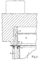
- FIG. 3 of the sealing strip 10 comprehensive section of FIG. 2 is enlarged. Notwithstanding Fig. 2, however, the sealing strip 10 is shown in its raised position, in which the package 16 is evacuated. As can easily be seen in FIG. 3, the lower film 6 and the upper film 8 are pressed together at the edge by the lower part 4 and the upper part 3 of the vacuum chamber 2. As a result, the package 16 is sealed at the edge. Through the suction opening 12a of the suction line 12, air can now be sucked out of the packaging 16 with a suitable negative pressure, for example by means of a suction pump in the suction direction S. The flow path between lower film 6 and upper film 8 to the suction line 12 is opened in this position.
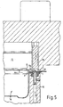
- FIG. 4 the same section is shown, wherein now the sealing strip 10, which is movable in the direction of the double arrow H, is lowered. As a result, the upper film 8 is pressed onto the lower film 6 in the region of the suction opening 12a of the suction pipe 12, whereby the suction opening 12a is closed.
- the position of the sealing strip 10 shown in FIG. 4 is set when a gas or gas mixture is to be supplied into the packaging 16.
- Fig. 5 which shows a cross section through a sectional plane in the region of a gas supply line 13
- a gas supply between lower film 6 and upper film 8 is possible.
- one or more inlet openings 13a are provided for this purpose in the edge web 7.
- An infeed gas can be directed in this position, as indicated by the arrows Z, via the gas supply line 13 into the package 16. Since in the same position of the sealing strip 10, the suction openings 12a are closed, there is no connection between the interior of the package 16 and the suction or vacuum system of the machine at this moment. Thus, a controlled gas supply to the interior of the package 16 is possible.
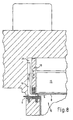
- FIG. 6 shows another variant of the invention, which can be used, for example, when the upper film 8 is narrower than the vacuum chamber 2.
- This can be seen, for example, in the cross-sectional illustration according to FIG.
- the suction and the gas supply takes place in the manner described below.
- lateral gas supply lines 19 projecting between the upper foil 8 and the lower foil 6 are provided, which open into the interior of the packaging 16 below the sealing strip 18.
- the sealing strip 18 is provided in this case at its lower edge with an elastic material 20, for example an elastomer. As can already be seen in FIG. 6, this elastomer 20 encloses the gas supply lines 19 in the lowered position of the sealing strip 18.
- FIG. 8 shows the sealing strip 18 in the raised position, which is taken during the evacuation process.
- the air between the upper and the lower film 6, 8 escape and laterally next to the gas supply line 19 in the upper region 21 of the vacuum chamber 2 get (vgL arrows S).
- the air in the package 16 is thus sucked.
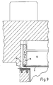
- FIG. 9 shows the lower position, provided for the gas supply, of the sealing strip 18 which can be moved in the direction of the double arrow H.
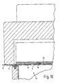
- the upper film 8 in the region of the gas supply line 19 is pressed from above on this. Offset in the longitudinal direction, however, presses the edge-mounted elastomer 20, the top film 8 directly on the lower film 6, as shown in Fig. 10 in the region of the gas supply line 19.
- the elastomer 20 conforms snugly against the gas supply line 19, so that a continuous pressure is exerted on the top film 8 and this can thus seal the packaging 16 at the edges in interaction with the bottom film 6.
- the interior of the packaging 16 can be filled with a desired gas or gas mixture by the gas supply line 19, without gas flow into the region of the suction system, in particular the vacuum chamber 2.
- a desired gas or gas mixture by the gas supply line 19, without gas flow into the region of the suction system, in particular the vacuum chamber 2.
- the packages 16 can be tightly sealed by the sealing plate 15 in the edge region of the package 16 within the sealing strips 10, 18 after filling with the desired gas.
- the illustrated embodiments are shown for simplicity only with a package 16.
- the invention can be readily applied to sealing stations where multiple packages 16 are arranged in multiple rows and / or columns. If these packagings 16 are produced coherently from a bottom foil 6 and are closed together with a top foil 8, then the same procedure can be chosen. Also in this case, the suction can be done via edge suction openings and marginal gas supply lines.
- one or more sealing strips 10, 18 provided in the region of the intermediate webs between individual packages this is basically not necessary.
- Essential in the invention is the closing of the interior of the package 16 relative to the suction system of the machine.
- the invention is also not limited to the arrangement of the upper and lower part 3, 4 of the sealing station 1 shown. It is readily apparent that the reverse arrangement of the gas supply from above through corresponding openings of the top film is also feasible and offers advantages of the invention. Likewise, it is irrelevant for the invention, whether upper part or lower part of the vacuum chamber are movable. In principle, the method can also be implemented according to the invention with an otherwise configured suction arrangement, provided that only a separation between the suction system and the interior of the packaging is provided.
Landscapes
- Engineering & Computer Science (AREA)
- Mechanical Engineering (AREA)
- Chemical & Material Sciences (AREA)
- Dispersion Chemistry (AREA)
- Vacuum Packaging (AREA)
- Closing Of Containers (AREA)
Applications Claiming Priority (1)
| Application Number | Priority Date | Filing Date | Title |
|---|---|---|---|
| DE102006047784 | 2006-10-06 |
Publications (2)
| Publication Number | Publication Date |
|---|---|
| EP1908689A2 true EP1908689A2 (fr) | 2008-04-09 |
| EP1908689A3 EP1908689A3 (fr) | 2008-04-23 |
Family
ID=38985383
Family Applications (1)
| Application Number | Title | Priority Date | Filing Date |
|---|---|---|---|
| EP07019244A Withdrawn EP1908689A3 (fr) | 2006-10-06 | 2007-10-01 | Baguette de calfeutrage pour le contrôle de l'introduction de gaz dans les paquets |
Country Status (6)
| Country | Link |
|---|---|
| US (1) | US20080104930A1 (fr) |
| EP (1) | EP1908689A3 (fr) |
| JP (1) | JP2008094498A (fr) |
| AU (1) | AU2007221858A1 (fr) |
| DE (1) | DE102007047058A1 (fr) |
| NZ (1) | NZ562266A (fr) |
Cited By (7)
| Publication number | Priority date | Publication date | Assignee | Title |
|---|---|---|---|---|
| EP2287077A1 (fr) * | 2009-08-13 | 2011-02-23 | Multivac Sepp Haggenmüller GmbH & Co. KG | Scellement par laser d'emballages |
| ITMO20090268A1 (it) * | 2009-11-04 | 2011-05-05 | Sarong Spa | Apparato e metodo di saldatura |
| ITBO20100045A1 (it) * | 2010-01-26 | 2011-07-27 | Gruppo Fabbri S P A | Apparato per il confezionamento in atmosfera modificata di prodotti posti in vassoi. |
| ITBO20100211A1 (it) * | 2010-04-08 | 2011-10-09 | Gruppo Fabbri S P A | Apparato a campane contrapposte, per il confezionamento in atmosfera modificata di prodotti posti in vassoi. |
| EP2484594A3 (fr) * | 2011-02-08 | 2012-11-07 | Multivac Sepp Haggenmüller GmbH & Co. KG | Machine d'emballage pour la fabrication d'un emballage en plusieurs couches |
| EP4001136A1 (fr) * | 2020-11-20 | 2022-05-25 | ULMA Packaging Technological Centre, S. COOP | Machine d'emballage à atmosphère modifiée |
| DE102021134192A1 (de) | 2021-12-22 | 2023-06-22 | Multivac Sepp Haggenmüller Se & Co. Kg | Siegelstation zum Versiegeln von Verpackungen |
Families Citing this family (11)
| Publication number | Priority date | Publication date | Assignee | Title |
|---|---|---|---|---|
| ITBO20110403A1 (it) * | 2011-07-07 | 2013-01-08 | Gruppo Fabbri Vignola Spa | Apparato a campane contrapposte per il confezionamento in atmosfera modificata di prodotti posti in vassoi. |
| DE102012005891A1 (de) * | 2012-03-23 | 2013-09-26 | Multivac Sepp Haggenmüller Gmbh & Co. Kg | Verpackungsmaschine mit Siegelstation zum Begasen einer Verpackung |
| ITBO20120549A1 (it) | 2012-10-09 | 2014-04-10 | Gruppo Fabbri Vignola Spa | Apparato a campane contrapposte, per il confezionamento in atmosfera modificata di prodotti posti in vassoi |
| ES2527611B1 (es) | 2013-07-24 | 2015-11-04 | Ulma Packaging Technological Center, S.Coop. | Máquina de envasado en atmósfera modificada, en segunda piel o en vacío, y método |
| EP3192641B1 (fr) | 2016-01-12 | 2021-06-09 | MULTIVAC Sepp Haggenmüller SE & Co. KG | Station de formage pour une machine d'emballage par emboutissage |
| AU2017228016B2 (en) * | 2016-03-04 | 2021-05-27 | Cryovac, Llc | Apparatus and process for vacuum skin packaging of a product and a vacuum skin package |
| DE102018114263A1 (de) * | 2018-06-14 | 2019-12-19 | Multivac Sepp Haggenmüller Se & Co. Kg | Füllstandsunabhängiges begasen |
| EP3733531B2 (fr) | 2019-05-03 | 2024-08-28 | Ulma Packaging, S.Coop. | Procédé et machine d'emballage de produits |
| ES2922355T3 (es) * | 2020-04-08 | 2022-09-13 | Ulma Packaging Tech Ct Coop | Método y máquina de envasado de productos |
| CN112678261B (zh) * | 2020-12-21 | 2022-10-28 | 广州铂海科技有限公司 | 一种高效真空抽吸包装装置 |
| DE102023121207A1 (de) | 2023-08-09 | 2025-02-13 | Multivac Sepp Haggenmüller Se & Co. Kg | Verfahren zum Schutzbegasen einer Verpackung sowie Begasungsstation |
Family Cites Families (9)
| Publication number | Priority date | Publication date | Assignee | Title |
|---|---|---|---|---|
| JPS4936998B1 (fr) * | 1966-02-09 | 1974-10-04 | ||
| US4294859A (en) * | 1975-04-14 | 1981-10-13 | Armour And Company | Process for packaging food |
| GB8702206D0 (en) * | 1987-01-31 | 1987-03-04 | Fgl Products Ltd | Valved container |
| US4779398A (en) * | 1987-02-06 | 1988-10-25 | W. R. Grace & Co.-Conn., Cryovac Div. | Method and apparatus for making gas flushed packages |
| US4777782A (en) * | 1987-06-05 | 1988-10-18 | Mahaffy & Harder Engineering Co. | Apparatus and methods for making differentially-conditioned package pairs |
| ATE133134T1 (de) * | 1989-08-30 | 1996-02-15 | Seawell Corp Nv | Verfahren und vorrichtung zum verpacken verderblicher güter |
| US5271207A (en) * | 1992-11-18 | 1993-12-21 | Moshe Epstein | Dual-function nozzle head for vacuum-packaging tooling |
| IL132708A (en) * | 1999-02-24 | 2004-12-15 | Hefestus Ltd | Packaging method and apparatus |
| JP2003212212A (ja) * | 2002-01-22 | 2003-07-30 | Nippon Tansan Gas Co Ltd | 密封充填装置 |
-
2007
- 2007-10-01 EP EP07019244A patent/EP1908689A3/fr not_active Withdrawn
- 2007-10-01 DE DE102007047058A patent/DE102007047058A1/de not_active Withdrawn
- 2007-10-04 US US11/905,844 patent/US20080104930A1/en not_active Abandoned
- 2007-10-05 NZ NZ562266A patent/NZ562266A/en unknown
- 2007-10-05 JP JP2007262296A patent/JP2008094498A/ja active Pending
- 2007-10-05 AU AU2007221858A patent/AU2007221858A1/en not_active Abandoned
Cited By (21)
| Publication number | Priority date | Publication date | Assignee | Title |
|---|---|---|---|---|
| US8357875B2 (en) | 2009-08-13 | 2013-01-22 | Multivac Sepp Haggenmuller Gmbh & Co. Kg | Laser sealing of packages |
| EP2287077A1 (fr) * | 2009-08-13 | 2011-02-23 | Multivac Sepp Haggenmüller GmbH & Co. KG | Scellement par laser d'emballages |
| ITMO20090268A1 (it) * | 2009-11-04 | 2011-05-05 | Sarong Spa | Apparato e metodo di saldatura |
| WO2011055325A3 (fr) * | 2009-11-04 | 2011-06-30 | Sarong Societa' Per Azioni | Appareil et procédé pour soudage |
| CN102712372A (zh) * | 2009-11-04 | 2012-10-03 | 萨龙股份公司 | 用于焊接的设备和方法 |
| ITBO20100045A1 (it) * | 2010-01-26 | 2011-07-27 | Gruppo Fabbri S P A | Apparato per il confezionamento in atmosfera modificata di prodotti posti in vassoi. |
| WO2011092103A1 (fr) * | 2010-01-26 | 2011-08-04 | Gruppo Fabbri S.P.A. | Appareil pour le conditionnement sous atmosphère modifiée de produits placés dans des barquettes |
| AU2011209249B2 (en) * | 2010-01-26 | 2016-02-11 | Gruppo Fabbri Vignola S.P.A. | Apparatus for modified atmosphere packaging of products placed in trays |
| US9150316B2 (en) * | 2010-01-26 | 2015-10-06 | Gruppo Fabbri Vignola S.P.A. | Apparatus for modified atmosphere packaging of products placed in trays |
| US20120285126A1 (en) * | 2010-01-26 | 2012-11-15 | Massimiliano Vaccari | Apparatus for Modified Atmosphere Packaging of Products Placed in Trays |
| ITBO20100211A1 (it) * | 2010-04-08 | 2011-10-09 | Gruppo Fabbri S P A | Apparato a campane contrapposte, per il confezionamento in atmosfera modificata di prodotti posti in vassoi. |
| WO2011124548A1 (fr) * | 2010-04-08 | 2011-10-13 | Gruppo Fabbri Vignola S.P.A. | Appareil à boîtiers opposés pour emballage sous atmosphère modifiée de produits disposés dans des plateaux |
| EP2555981B1 (fr) | 2010-04-08 | 2018-06-27 | Gruppo Fabbri Vignola S.p.A. | Procédé pour le conditionnement de produits dans des barquettes sous atmosphère modifiée |
| DE102011010601B4 (de) * | 2011-02-08 | 2013-09-05 | Multivac Sepp Haggenmüller Gmbh & Co. Kg | Verpackungsmaschine zum Herstellen einer Mehrlagenpackung |
| US8615973B2 (en) | 2011-02-08 | 2013-12-31 | Multivac Sepp Haggenmueller Gmbh & Co. Kg | Packaging machine for producing a multilayer package |
| EP2484594A3 (fr) * | 2011-02-08 | 2012-11-07 | Multivac Sepp Haggenmüller GmbH & Co. KG | Machine d'emballage pour la fabrication d'un emballage en plusieurs couches |
| EP4001136A1 (fr) * | 2020-11-20 | 2022-05-25 | ULMA Packaging Technological Centre, S. COOP | Machine d'emballage à atmosphère modifiée |
| US11708185B2 (en) | 2020-11-20 | 2023-07-25 | Ulma Packaging Technological Center, S Coop. | Modified atmosphere packaging machine |
| DE102021134192A1 (de) | 2021-12-22 | 2023-06-22 | Multivac Sepp Haggenmüller Se & Co. Kg | Siegelstation zum Versiegeln von Verpackungen |
| EP4219323A1 (fr) | 2021-12-22 | 2023-08-02 | MULTIVAC Sepp Haggenmüller SE & Co. KG | Poste de scellage pour sceller des emballages |
| US11866210B2 (en) | 2021-12-22 | 2024-01-09 | Multivac Sepp Haggenmueller Se & Co. Kg | Sealing station for sealing packaging units |
Also Published As
| Publication number | Publication date |
|---|---|
| EP1908689A3 (fr) | 2008-04-23 |
| AU2007221858A1 (en) | 2008-04-24 |
| DE102007047058A1 (de) | 2008-04-10 |
| JP2008094498A (ja) | 2008-04-24 |
| US20080104930A1 (en) | 2008-05-08 |
| NZ562266A (en) | 2009-03-31 |
Similar Documents
| Publication | Publication Date | Title |
|---|---|---|
| EP1908689A2 (fr) | Baguette de calfeutrage pour le contrôle de l'introduction de gaz dans les paquets | |
| EP2251265B1 (fr) | Machine d'emballage | |
| DE3316065C2 (de) | Verfahren zum Füllen, Entlüften und Verschließen von Säcken | |
| DE3941183A1 (de) | Verpackungsmaschine zum herstellen einer ein produkt aufnehmenden wiederverschliessbaren packung | |
| DE4026807C2 (fr) | ||
| EP2484594B1 (fr) | Machine d'emballage pour la fabrication d'un emballage en plusieurs couches | |
| CH464775A (de) | Verfahren zum Verpacken von Ware, insbesondere Essware, unter Einschluss von Schutzgas und Einrichtung zur Durchführung des Verfahrens | |
| EP2384981B1 (fr) | Station de scellage pour une machine d'emballage | |
| EP2004491A1 (fr) | Procédé de fabrication d'un emballage et machine à emballer | |
| DE19915040A1 (de) | Vorrichtung und Verfahren zum Trennen einer Folie mit wenigstens zwei Laminatschichten und Verpackungsmaschine mit einer solchen Vorrichtung sowie Packung mit einer Oberfolie aus wenigstens zwei Laminatschichten | |
| EP3052396A1 (fr) | Contenant d'emballage flexible | |
| EP2284085B1 (fr) | Plat cuisiné emballé et son procédé de fabrication | |
| WO2007131683A2 (fr) | Dispositif pour gazéifier et/ou dégazer des récipients | |
| DE69012766T2 (de) | Vakuumverpackungsvorrichtung. | |
| DE102015205221A1 (de) | Tiefziehverpackungsmaschine, Verfahren und Verpackung | |
| EP3880559A2 (fr) | Emballage double à chargement de gaz de protection différent | |
| EP0533134A1 (fr) | Station de scellage | |
| DE69703776T2 (de) | Vakuumverpackungsvorrichtung, insbesondere für Nahrungsmittel | |
| DE202009010873U1 (de) | Abgepacktes Fertiggericht | |
| DE102009037107B4 (de) | Abgepacktes Fertiggericht und Verfahren zu seiner Herstellung | |
| DE2335021A1 (de) | Verfahren und vorrichtung fuer die verpackung von ware | |
| DE202014101589U1 (de) | Verpackungsmaschine | |
| DE102008039158B4 (de) | Vorrichtung zum Siegeln von Packungen | |
| DE1058924B (de) | Vorrichtung zum Evakuieren und Begasen von Packungen | |
| DE102005035489A1 (de) | Vorrichtung und Verfahren zum Beschichten von Verpackungen |
Legal Events
| Date | Code | Title | Description |
|---|---|---|---|
| PUAI | Public reference made under article 153(3) epc to a published international application that has entered the european phase |
Free format text: ORIGINAL CODE: 0009012 |
|
| PUAL | Search report despatched |
Free format text: ORIGINAL CODE: 0009013 |
|
| AK | Designated contracting states |
Kind code of ref document: A2 Designated state(s): AT BE BG CH CY CZ DE DK EE ES FI FR GB GR HU IE IS IT LI LT LU LV MC MT NL PL PT RO SE SI SK TR |
|
| AX | Request for extension of the european patent |
Extension state: AL BA HR MK RS |
|
| AK | Designated contracting states |
Kind code of ref document: A3 Designated state(s): AT BE BG CH CY CZ DE DK EE ES FI FR GB GR HU IE IS IT LI LT LU LV MC MT NL PL PT RO SE SI SK TR |
|
| AX | Request for extension of the european patent |
Extension state: AL BA HR MK RS |
|
| 17P | Request for examination filed |
Effective date: 20080710 |
|
| AKX | Designation fees paid |
Designated state(s): AT BE BG CH CY CZ DE DK EE ES FI FR GB GR HU IE IS IT LI LT LU LV MC MT NL PL PT RO SE SI SK TR |
|
| GRAP | Despatch of communication of intention to grant a patent |
Free format text: ORIGINAL CODE: EPIDOSNIGR1 |
|
| STAA | Information on the status of an ep patent application or granted ep patent |
Free format text: STATUS: THE APPLICATION IS DEEMED TO BE WITHDRAWN |
|
| 18D | Application deemed to be withdrawn |
Effective date: 20090813 |