EP1908682B1 - Navigationsprozessor, Prozessoranordnung und Messsystem mit einem solchen Navigationsprozessor sowie Verfahren zur Messung einer Position und einer Ausrichtung in einem Unterwassersystem - Google Patents
Navigationsprozessor, Prozessoranordnung und Messsystem mit einem solchen Navigationsprozessor sowie Verfahren zur Messung einer Position und einer Ausrichtung in einem Unterwassersystem Download PDFInfo
- Publication number
- EP1908682B1 EP1908682B1 EP08100314A EP08100314A EP1908682B1 EP 1908682 B1 EP1908682 B1 EP 1908682B1 EP 08100314 A EP08100314 A EP 08100314A EP 08100314 A EP08100314 A EP 08100314A EP 1908682 B1 EP1908682 B1 EP 1908682B1
- Authority
- EP
- European Patent Office
- Prior art keywords
- processor
- navigation processor
- underwater
- data
- navigation
- Prior art date
- Legal status (The legal status is an assumption and is not a legal conclusion. Google has not performed a legal analysis and makes no representation as to the accuracy of the status listed.)
- Expired - Lifetime
Links
Images


Classifications
-
- B—PERFORMING OPERATIONS; TRANSPORTING
- B63—SHIPS OR OTHER WATERBORNE VESSELS; RELATED EQUIPMENT
- B63J—AUXILIARIES ON VESSELS
- B63J99/00—Subject matter not provided for in other groups of this subclass
-
- B—PERFORMING OPERATIONS; TRANSPORTING
- B63—SHIPS OR OTHER WATERBORNE VESSELS; RELATED EQUIPMENT
- B63B—SHIPS OR OTHER WATERBORNE VESSELS; EQUIPMENT FOR SHIPPING
- B63B79/00—Monitoring properties or operating parameters of vessels in operation
- B63B79/10—Monitoring properties or operating parameters of vessels in operation using sensors, e.g. pressure sensors, strain gauges or accelerometers
- B63B79/15—Monitoring properties or operating parameters of vessels in operation using sensors, e.g. pressure sensors, strain gauges or accelerometers for monitoring environmental variables, e.g. wave height or weather data
-
- B—PERFORMING OPERATIONS; TRANSPORTING
- B63—SHIPS OR OTHER WATERBORNE VESSELS; RELATED EQUIPMENT
- B63B—SHIPS OR OTHER WATERBORNE VESSELS; EQUIPMENT FOR SHIPPING
- B63B79/00—Monitoring properties or operating parameters of vessels in operation
- B63B79/20—Monitoring properties or operating parameters of vessels in operation using models or simulation, e.g. statistical models or stochastic models
-
- B—PERFORMING OPERATIONS; TRANSPORTING
- B63—SHIPS OR OTHER WATERBORNE VESSELS; RELATED EQUIPMENT
- B63B—SHIPS OR OTHER WATERBORNE VESSELS; EQUIPMENT FOR SHIPPING
- B63B79/00—Monitoring properties or operating parameters of vessels in operation
- B63B79/40—Monitoring properties or operating parameters of vessels in operation for controlling the operation of vessels, e.g. monitoring their speed, routing or maintenance schedules
-
- B—PERFORMING OPERATIONS; TRANSPORTING
- B63—SHIPS OR OTHER WATERBORNE VESSELS; RELATED EQUIPMENT
- B63C—LAUNCHING, HAULING-OUT, OR DRY-DOCKING OF VESSELS; LIFE-SAVING IN WATER; EQUIPMENT FOR DWELLING OR WORKING UNDER WATER; MEANS FOR SALVAGING OR SEARCHING FOR UNDERWATER OBJECTS
- B63C11/00—Equipment for dwelling or working underwater; Means for searching for underwater objects
- B63C11/34—Diving chambers with mechanical link, e.g. cable, to a base
- B63C11/36—Diving chambers with mechanical link, e.g. cable, to a base of closed type
- B63C11/42—Diving chambers with mechanical link, e.g. cable, to a base of closed type with independent propulsion or direction control
-
- B—PERFORMING OPERATIONS; TRANSPORTING
- B63—SHIPS OR OTHER WATERBORNE VESSELS; RELATED EQUIPMENT
- B63G—OFFENSIVE OR DEFENSIVE ARRANGEMENTS ON VESSELS; MINE-LAYING; MINE-SWEEPING; SUBMARINES; AIRCRAFT CARRIERS
- B63G8/00—Underwater vessels, e.g. submarines; Equipment specially adapted therefor
- B63G8/42—Towed underwater vessels
-
- E—FIXED CONSTRUCTIONS
- E21—EARTH OR ROCK DRILLING; MINING
- E21B—EARTH OR ROCK DRILLING; OBTAINING OIL, GAS, WATER, SOLUBLE OR MELTABLE MATERIALS OR A SLURRY OF MINERALS FROM WELLS
- E21B19/00—Handling rods, casings, tubes or the like outside the borehole, e.g. in the derrick; Apparatus for feeding the rods or cables
- E21B19/002—Handling rods, casings, tubes or the like outside the borehole, e.g. in the derrick; Apparatus for feeding the rods or cables specially adapted for underwater drilling
-
- E—FIXED CONSTRUCTIONS
- E21—EARTH OR ROCK DRILLING; MINING
- E21B—EARTH OR ROCK DRILLING; OBTAINING OIL, GAS, WATER, SOLUBLE OR MELTABLE MATERIALS OR A SLURRY OF MINERALS FROM WELLS
- E21B41/00—Equipment or details not covered by groups E21B15/00 - E21B40/00
- E21B41/04—Manipulators for underwater operations, e.g. temporarily connected to well heads
-
- G—PHYSICS
- G01—MEASURING; TESTING
- G01S—RADIO DIRECTION-FINDING; RADIO NAVIGATION; DETERMINING DISTANCE OR VELOCITY BY USE OF RADIO WAVES; LOCATING OR PRESENCE-DETECTING BY USE OF THE REFLECTION OR RERADIATION OF RADIO WAVES; ANALOGOUS ARRANGEMENTS USING OTHER WAVES
- G01S19/00—Satellite radio beacon positioning systems; Determining position, velocity or attitude using signals transmitted by such systems
- G01S19/38—Determining a navigation solution using signals transmitted by a satellite radio beacon positioning system
- G01S19/39—Determining a navigation solution using signals transmitted by a satellite radio beacon positioning system the satellite radio beacon positioning system transmitting time-stamped messages, e.g. GPS [Global Positioning System], GLONASS [Global Orbiting Navigation Satellite System] or GALILEO
- G01S19/42—Determining position
- G01S19/45—Determining position by combining measurements of signals from the satellite radio beacon positioning system with a supplementary measurement
- G01S19/47—Determining position by combining measurements of signals from the satellite radio beacon positioning system with a supplementary measurement the supplementary measurement being an inertial measurement, e.g. tightly coupled inertial
-
- G—PHYSICS
- G01—MEASURING; TESTING
- G01S—RADIO DIRECTION-FINDING; RADIO NAVIGATION; DETERMINING DISTANCE OR VELOCITY BY USE OF RADIO WAVES; LOCATING OR PRESENCE-DETECTING BY USE OF THE REFLECTION OR RERADIATION OF RADIO WAVES; ANALOGOUS ARRANGEMENTS USING OTHER WAVES
- G01S5/00—Position-fixing by co-ordinating two or more direction or position line determinations; Position-fixing by co-ordinating two or more distance determinations
- G01S5/0009—Transmission of position information to remote stations
-
- G—PHYSICS
- G01—MEASURING; TESTING
- G01S—RADIO DIRECTION-FINDING; RADIO NAVIGATION; DETERMINING DISTANCE OR VELOCITY BY USE OF RADIO WAVES; LOCATING OR PRESENCE-DETECTING BY USE OF THE REFLECTION OR RERADIATION OF RADIO WAVES; ANALOGOUS ARRANGEMENTS USING OTHER WAVES
- G01S5/00—Position-fixing by co-ordinating two or more direction or position line determinations; Position-fixing by co-ordinating two or more distance determinations
- G01S5/18—Position-fixing by co-ordinating two or more direction or position line determinations; Position-fixing by co-ordinating two or more distance determinations using ultrasonic, sonic or infrasonic waves
- G01S5/22—Position of source determined by co-ordinating a plurality of position lines defined by path-difference measurements
-
- G—PHYSICS
- G01—MEASURING; TESTING
- G01S—RADIO DIRECTION-FINDING; RADIO NAVIGATION; DETERMINING DISTANCE OR VELOCITY BY USE OF RADIO WAVES; LOCATING OR PRESENCE-DETECTING BY USE OF THE REFLECTION OR RERADIATION OF RADIO WAVES; ANALOGOUS ARRANGEMENTS USING OTHER WAVES
- G01S15/00—Systems using the reflection or reradiation of acoustic waves, e.g. sonar systems
- G01S15/74—Systems using reradiation of acoustic waves, e.g. IFF, i.e. identification of friend or foe
-
- G—PHYSICS
- G01—MEASURING; TESTING
- G01S—RADIO DIRECTION-FINDING; RADIO NAVIGATION; DETERMINING DISTANCE OR VELOCITY BY USE OF RADIO WAVES; LOCATING OR PRESENCE-DETECTING BY USE OF THE REFLECTION OR RERADIATION OF RADIO WAVES; ANALOGOUS ARRANGEMENTS USING OTHER WAVES
- G01S19/00—Satellite radio beacon positioning systems; Determining position, velocity or attitude using signals transmitted by such systems
- G01S19/38—Determining a navigation solution using signals transmitted by a satellite radio beacon positioning system
- G01S19/39—Determining a navigation solution using signals transmitted by a satellite radio beacon positioning system the satellite radio beacon positioning system transmitting time-stamped messages, e.g. GPS [Global Positioning System], GLONASS [Global Orbiting Navigation Satellite System] or GALILEO
- G01S19/40—Correcting position, velocity or attitude
- G01S19/41—Differential correction, e.g. DGPS [differential GPS]
-
- G—PHYSICS
- G01—MEASURING; TESTING
- G01S—RADIO DIRECTION-FINDING; RADIO NAVIGATION; DETERMINING DISTANCE OR VELOCITY BY USE OF RADIO WAVES; LOCATING OR PRESENCE-DETECTING BY USE OF THE REFLECTION OR RERADIATION OF RADIO WAVES; ANALOGOUS ARRANGEMENTS USING OTHER WAVES
- G01S19/00—Satellite radio beacon positioning systems; Determining position, velocity or attitude using signals transmitted by such systems
- G01S19/38—Determining a navigation solution using signals transmitted by a satellite radio beacon positioning system
- G01S19/39—Determining a navigation solution using signals transmitted by a satellite radio beacon positioning system the satellite radio beacon positioning system transmitting time-stamped messages, e.g. GPS [Global Positioning System], GLONASS [Global Orbiting Navigation Satellite System] or GALILEO
- G01S19/42—Determining position
- G01S19/43—Determining position using carrier phase measurements, e.g. kinematic positioning; using long or short baseline interferometry
- G01S19/44—Carrier phase ambiguity resolution; Floating ambiguity; LAMBDA [Least-squares AMBiguity Decorrelation Adjustment] method
Definitions
- the present invention relates to a navigation processor, a processor arrangement comprising such a navigation processor, a measuring system comprising such a navigation processor and a method of measuring position and attitude of an underwater system.
- WO 99/61307 which is considered to be the closest prior art, discloses an apparatus for deploying an object to an underwater target position, the apparatus being provided with a beacon to transmit acoustic rays and a plurality of thrusters to control positioning of the apparatus with respect to the underwater target position.
- the prior art apparatus is used for deploying and/or recovering loads up to 1000 tons or more on the seabed at great depths, for instance, up to 3,000 meter or more.
- the apparatus is controlled by controlling equipment on board of a vessel floating on the sea surface.
- the controlling equipment needs to know the exact location of the apparatus as accurately as possible.
- the beacon on board of the apparatus transmits acoustic rays through the sea water to the vessel.
- An appropriate acoustic receiver receives these acoustic rays and converts them into electrical signals used to calculate the position of the apparatus with respect to the vessel.
- the object of the invention is therefore to further enhance the accuracy of the location measurement of such an apparatus during use in sea water or any other fluid. Moreover, such location measurement is needed on-line (real-time).
- the present invention provides a navigation processor as defined in claim 1: a navigation processor interfaced to an acoustic processor and to a DGPS surface positioning equipment on board a vessel, the navigation processor being arranged to receive
- a processor arrangement comprising a navigation processor and an acoustic processor, said navigation processor being interfaced to said acoustic processor and to a DGPS surface positioning equipment on board a vessel, the navigation processor being arranged to receive
- a measuring system comprising a navigation processor, an acoustic processor and an underwater system, said navigation processor being interfaced to said acoustic processor and to a DGPS surface positioning equipment on board a vessel, and the underwater system comprising a fiber optic gyrocompass, a Doppler log unit and a depth sensor, the fiber optic gyrocompass including heave, roll and pitch sensors, the navigation processor being arranged to receive
- a navigation processor on board a vessel comprising
- Figure 1 shows a schematic overview of a FPSO (floating, production, storage and offloading system) dedicated to offshore petrochemical recoveries.
- FPSO floating, production, storage and offloading system
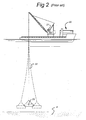
- Figure 2 shows a crane vessel according to the prior art and displaying a load rigged to the crane block with relatively long wire ropes whereby it is possible to see that the control of the load is virtually impossible at great depth.
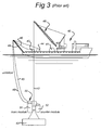
- Figure 3 shows a crane vessel and an underwater system for deploying and/or recovering a load to and/or from the seabed according to the prior art.
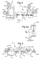
- FIG. 4 shows a detailed overview of a possible embodiment of the underwater system.
- Figure 4a shows a detailed overview of one of the rotatable thrusters.
- Figure 5 shows the underwater system viewed from above.
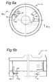
- FIGS 6a and 6b schematically show the underside of the main module with some detectors.
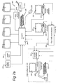
- Figure 7a shows a schematic block diagram of the electronic equipment on board of the vessel.
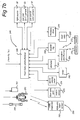
- Figure 7b shows a schematic block diagram of the electronic equipment related to an acoustic array and related to the underwater system.
- Figure 8 shows the definition of three different coordinate systems used during driving the underwater system to its target position.
- the layout presents a FPSO 1 with swivel production stack 11 from which risers 2 depart, said risers connecting to their riser bases 3 at the seabed 4.
- the FPSO 1 it is paramount for the FPSO 1 to remain within an allowable dynamic excursion range and therefor the FPSO 1 is moored to the seabed 4 by means of mooring legs 5 which are held by anchors 6, or alternatively by piles.
- anchors can be used with a weight of 50 ton and more, which are placed at the seabed 4 with an accuracy to within several meters. Moreover not only is the anchor 6 itself very heavy, but the mooring leg attached to the anchor 6 has a weight that equals several times the weight of the anchor 6 itself.
- FIG. 2 shows a vessel 20, according to the prior art, having hoisting means thereon, like a crane 21.
- the crane 21 is provided with a hoisting wire 22, by means of which an object or a load 4 can be put on the seabed 5.
- a hoisting wire 22 by means of which an object or a load 4 can be put on the seabed 5.
- an object or a load 4 can be put on the seabed 5.
- the load 23 it is necessary to move the surface support together with the crane 21.
- FIG. 3 shows a crane vessel 40 provided with an underwater apparatus or system 50 for deploying a load 43 on the seabed 4.
- the vessel 40 comprises first hoist means, for example a winch 41, provided with a first hoist wire 42.
- first hoist wire 42 By means of this hoist wire 42 the load 43, for instance a template can be deployed and placed at the bottom of the sea.
- the apparatus or system 50 has been secured to the lifting wire 42.
- a preferred embodiment of the system 50 will be described with reference to figures 4, 5 , 6a and 6b .
- the system 50 may engage the end of the lifting wire 42. Alternatively, the system 50 may directly engage the load 43 itself.
- the system further comprises a second or counter module 52. This counter-module 52 is also provided with thrusters 56(i). In use the thrusters of the main-module 51 and of the counter-module 52 will be positioned at opposite sides of the lifting wire 42.
- the system 50 is coupled to the vessel 40 by means of a second lifting wire 45, which can be operated using second hoist means, for instance a second winch 44.
- the second hoist wire 45 is, for instance, set overboard by means of an A-frame 49.
- the second winch 44 and the second hoist wire 45 will be normally lighter than the first hoist means 48 and the primary hoist wire 42, respectively.
- the system 50 is further connected to the vessel 40 by means of an umbilical 46.
- This umbilical 46 can be attached to the hoist wire 45 or can be lowered from a tertiary winch 47 separately.
- the electricity wiring for providing power to the system 50, as well as electrical wiring or optical fibers are for instance accommodated in the umbilical.
- In the system 50 usually means are provided to convert the electrical power into hydraulic power.
- the hydraulic power consequently will be used for controlling i.a. the thrusters 56(i) and auxiliary tooling amenities.
- a counter-torque can be exerted at the hoist wire 42 in both directions.
- an anti-twist device is formed.
- the distance between the main-module 51 and the counter-module 52 can be altered.
- Figure 4 shows a detailed overview of a possible embodiment of the system 50 for deploying a load 43 on the seabed 4.
- Figure 5 shows the system according to figure 4 , from above.
- the system 50 comprises the main-module 51, the counter-module 52 and an arm 53.
- the arm 53 can be detached from the main-module 51. That means that the main-module 51 can also be used separately, as a modular system.
- the arm 53 is provided with a recess 54. On opposite sides of this recess 54 two jacks 57, 58 are provided, at least one of which can be moved relative to the other. In between the end surfaces of these jacks 57, 58 an object, such as a crane-block of load 43, can be clamped.
- the respective ends of the jacks are accommodated with clamping shoes lined with a friction element, from a high friction material such as dedicated rubber.
- the thrusters 56(i) can be used to position the system 50 relative to a target area on the seabed 4.
- the thrusters 56(i) can be actuated from a first position mainly inside the system 50, to a position in which the thrusters projects out of the system 50.
- the two upper thrusters 56(2), 56(3) are rotatable with respect to the underwater system 50. They are, for instance, installed on respective rotary actuators 65(1), 65(2). The purpose thereof will be explained later.
- Thruster 56(2) has been shown on an enlarged scale in figure 4a .
- FIG 5 it is shown that there are two positions 61, 62 on top of the main-module 51 to connect the main module to the second lifting wire 45 and/or to the umbilical 46.
- position 61 can be used separately position 61 can be used.
- the main-module 61 will be balanced when the module 61 is deployed, both in the air and underwater.
- an auxiliary counterweight 55 can be secured to the system 50.
- the apparatus 50 will not have any buoyancy.
- the arm 53 is provided with holes 59, in order to avoid structural damage due to an increasing pressure while being lowered and to ensure quick drainage during the recovery phase.
- the counter-module 52 can be moved relative to the main-module 51. This can be accomplished by using jacks 64a.
- the module 51 comprises an outer frame and an inner frame (both not shown).
- the inner frame preferably is cylinder-shaped.
- the module 51 is, for instance, partly made of high-tensile steel and thereby designed to be used as integral part of either the first 42 or second hoist wire 45. This means that the top side of the module 51 will be connected to a first part of the hoist wire 45, and that the underside of the module 51 will be connected to a second part of the hoist wire 45, or the underside of the module 51 will be attached directly to the load. In this way the load on the hoist wire will be transferred through the module 51.
- the module 51 is provided with a thruster drive 270 for converting electrical power, delivered through the umbilical 46, into hydraulic power.
- This thruster drive 270 may comprise motors, a pump, a manifold and a hydraulic reservoir.
- Such converting means are known to persons skilled in the art and need no further explanation here.
- the module 51 further comprises sensor means and control means that will be explained in detail below.
- the module 51 is equipped with a sensor junction box.
- the module 51 comprises light-sources 87, a gyrocompass 256 including heave, roll and pitch sensors, a pan and tilt color camera 97, a USBL responder 255 including a digiquartz depth sensor 253, a sound velocity meter 258, and a sonardyne mini Rovnav 264.
- a pan and S.I.T. camera 93 At the underside of the module 51 are mounted on several platforms light sources 94, a pan and S.I.T. camera 93, an altimeter 262, a Doppler log unit 266, and a dual head scanning sonar 260. They are installed there to have only clear sea water below them, in use. They are schematically shown in figures 6a and 6b . It is to be understood that they may be located elsewhere, e.g., at the underside of module 52.
- load cells 268 are part of the system 51. All these components are schematically indicated in figure 7b .
- the use of high resolution sonar equipment 260 together with a distance log, measured by Doppler log unit 266, is important to achieve the required accuracy, once the load has reached its intended depth.
- the sonar equipment 260 will be used to determine the position with respect to at least one object positioned at the seabed. Using the distance log, it will then be possible to dissociate the positioning activities from the surface support, as well as from any other acoustic transponder devices such as LBL (Long Base Line) arrays (or other, e.g., USBL), while accuracy in the order of centimeters will be achieved within a large radius.
- LBL Long Base Line
- Figure 7a shows the electronic equipment 200 installed on the vessel 40, whereas figure 7b shows deployable acoustic array 250 with velocity meter 248 and a gyro compass 252. Figure 7b also shows underwater electronic equipment 249 installed on the underwater system 50.
- the equipment shown in figure 7a comprises four processors: a navigation processor 202, acoustic processor 224, a sonar control processor 236, and a thruster control processor 240.
- the navigation processor 202 is interfaced to the other three processors 224, 236, 240 for mutual communications and complementarity.
- the navigation processor 202 is also interfaced to a surface positioning equipment DGPS (Differential Global Positioning System) 204, a vessel gyrocompass 206, four display units 208, 210, 212, 214, a printer unit 218, a keyboard 220, a mouse 222, and a fiber optic (de)multiplexer unit 244.
- DGPS Direct Global Positioning System
- a video splitter 216 may be provided to transmit one SVGA signal output of the navigation processor 202 to two or more display units.
- display units 212, 214 are connected to the navigation processor 202 via video splitter 216.
- the fiber optic (de)multiplexer unit 244 is also connected to the acoustic processor 224, the sonar control processor 236, and the thruster control processor 240.
- the acoustic processor 224 is connected to a command and control unit 226 which is connected to a keyboard 230, a mouse 232 and a display unit 228, all together forming a USBL surface unit 234.
- the acoustic processor 224 is connected to deployable acoustic array 250 with motion sensor unit 252 and velocity meter 248.
- the acoustic array 250 is, preferably, mounted 2.5 meters below the keel of vessel 40.
- the fiber optic (de)multiplexer unit 244 is connected to a further fiber optic (de)multiplexer 246 installed on the underwater system 50.
- An optical fiber interconnecting both fiber optic (de)multiplexers 244, 246 is preferably accommodated in umbilical 46 ( figure 3 ).
- the sonar control processor 236 is connected to a display unit 238.
- the thruster control processor 240 is connected to a display unit 242.
- the underwater equipment 249 is shown in figure 7b in the form of a block diagram.
- the USBL responder 255 with digiquartz depth sensor 253, a gyrocompass with motion sensors 256, (removable) sound velocity meter 258, a dual head scanning sonar 260, altimeter 262, sonardyne mini Rovnav 264, Doppler log 266, load cells 268, and thruster drive control 270 are all connected to the fiber optic (de)multiplexer 246.
- figure 7b shows two beacons 272, 274 that can be installed on the seabed or on the load to be deployed (or on other structures already on the seabed).
- These beacons 272, 274 can, e.g., be interrogated by means of the sonardyne mini Rovnav 264 (or equivalent equipment) to transmit acoustic signals back to the system 50 that can be used by the system 50 itself to determine and measure distances and orientations relative to these beacons.
- Such an acoustic telemetry link results in very high precision relative position measurements.
- the number of such beacons is not limited to the two shown in figure 7b .
- the navigation processor 202 is collecting the surface positioning equipment data (DGPS receivers, DGPS corrections, vessel's gyrocompass and vessel's motion sensors 204 and 206), in order to calculate and display the vessel's attitude and its fixed offsets.
- DGPS receivers DGPS corrections
- vessel's gyrocompass vessel's motion sensors 204 and 206
- the navigation processor 202 Via the fiber optic (de)multiplexers 244 and 246, the navigation processor 202 sends different settings to the navigation instruments of the system 50, i.e., Doppler log 266, altimeter 262, and gyrocompass and motion sensors 256. After setting up, it receives the data from those instruments, as well as, via the acoustic processor 224, the range/bearing and depth data of the system 50 to calculate and to display the attitudes and absolute coordinates of the system 50.
- the navigation processor 202 sends different settings to the navigation instruments of the system 50, i.e., Doppler log 266, altimeter 262, and gyrocompass and motion sensors 256. After setting up, it receives the data from those instruments, as well as, via the acoustic processor 224, the range/bearing and depth data of the system 50 to calculate and to display the attitudes and absolute coordinates of the system 50.
- An integrated software in the navigation processor 202 has been developed, including a dynamic positioning controller software able to work in manual or automode to decide the intended heading of the system 50 and to select between many way points and to carry out the intended positioning.
- the operator on board of the vessel can input offsets to the selected way point, the offsets being input with XY coordinates relative to the heading of the system 50.
- Embarked gyrocompass 256 including heave, roll and pitch sensors 88 on board of the system 50 provides data as to the exact attitudes of both the system 50 and the load 43 to be installed on the sea bed. At the surface of the sea, in a control van, operators are able to check those attitudes on-line (real-time), during descent but also once the load 43 is laying on the sea bed for final verification.
- the vessel gyrocompass 206 is transmitting the vessel's heading to the navigation processor 202.
- the navigation processor 202 will use this vessel's heading to calculate different offsets.
- the display units 208, 210, 212, and 214 are arranged to display navigation settings, a view of the sea bed, a view of the surface, in the control van for the operators and another one on the vessel bridge for the marine department operators.
- the USBL command and control unit 226 consists of a personal computer providing control and configuration of the system and displaying the man-machine-interface for operator control.
- the acoustic processor 224 preferably, consists of one VME rack which performs correlation process on received signals, corrections to bathy-celerimetry and vessel's attitude. Moreover, it calculates coordinates of any beacon used.
- the acoustic processor 224 is linked to the navigation processor 202 through Eternet.
- the acoustic array 250 includes means for transmission and reception.
- the acoustic array 250 can be used as a transducer to acoustically communicate with one or more beacons.
- Such a transducer mode is advantageous when the umbilical 46 fails and is unable to transmit interrogation signals down to the system 50. Then, acoustic interrogation signals can be transmitted down by the transducer directly through the sea water. In all other cases, the acoustic array 250 will be used in a reception mode. Reception is done with two orthogonal reception bases which measure distances and bearing angles of beacons relative to the acoustic array 250. Each reception base includes two transducers. Each received signal is amplified, filtered and transferred to the acoustic processor 224 for digital signal processing.
- the sound velocity meter 248 installed on the acoustic array 250 is updating in real-time the critical and unsettled sound velocity profile situated just underneath the vessel 40. This is of great importance since turbulences of the sea water appear to be very heavy in these layers just underneath the vessel 40.
- the gyrocompass 252 is preferably used as motion sensor unit transmitting the acoustic array attitude to the acoustic processor 224 in order to rectify data as to the position of the system 50 sub-sea.
- the beacon 254 is working in a responder mode and has the following characteristics:
- the beacon 254 can also be used in a transponder mode. Then, the beacon 254 is triggered by a surface acoustic signal transmitted by the acoustic array 250 and then delivers acoustic reply signals to the acoustic array 250 through a coded acoustic signal.
- the digiquartz depth sensor 253 included in the beacon 254 allows transmitting very accurate depth data of the system 50 to the acoustic processor 224.
- the acoustic processor 224 uses these data to improve the calculation of the sub-sea positioning of the system 50 and its load 43.
- the sound velocity meter 258, mounted on the underwater system 50 is transmitting data as to the velocity of sound in sea water at the depth of the underwater system 50 to the acoustic processor 224 during descent and recovery.
- the sound velocity data is used to update calculated sound velocity profiles in the sea water as a function of depth in real-time and to calculate acoustic ray bending from these profiles as function of depth in the sea water and thus to correct calculations of the sub-sea position of the system 50.
- the dual head scanning sonar 260 is used to measure ranges and bearings of the system 50 to any man-made or natural target on the seabed and to output corresponding data as digital values to the navigation processor 202.
- the positions of such man-made or natural targets can either be predefined or the navigation system can allocate coordinates to each of the selected objects. After the objects have been given coordinates, they can be used as navigation references in a local coordinate system. This results in an accuracy of 0.1 meter in relative coordinates.
- the altimeter 262 mounted on the system 50 is measuring the vertical distance of the underwater system 50 to the seabed and transmits output measuring data to the acoustic processor 224.
- the Doppler log unit 266 provides data as to the value and direction of the sea water current at the depth of the underwater system 50. These data are used in two ways.
- the data received from the Doppler log unit 266 and the gyrocompass with motion sensor 256 is used by the acoustic processor 224 to smooth on-line (real-time) the random noise related to using USBL.
- a filter is used, e.g., a Kalman filter, a Salomonsen filter, a Salomonsen light filter, or any other suitable filter in the main processor unit 224.
- filters are known to persons skilled in the art. A brief summary can be found in appendix A.
- the output data of the Doppler log unit 266 regarding current strength, current direction, together wit data regarding present and intended heading of the underwater system 50 are transmitted to the thruster control processor 240 via the navigation processor 202. Based on the intended direction the thruster drive control 270 will be automatically controlled. Manual control may also be provided for.
- the Doppler log unit 266 (or any other suitable sensor) is used to measure temperature and/or salinity of the sea water surrounding the system 50. Data as to local temperature and/or salinity is transmitted to the navigation processor 202 that calculates and updates temperature and/or salinity profiles as a function of depth in the sea water. These data are also used to determine acoustic ray bending through the sea water and, thus, to correct calculations of the position of the system 50.
- the sonardyne mini Rovnav 264 is optional and may be used to provide relative position of the system 50 to local beacons on the seabed as explained above.
- a Long Base Line (LBL) array may already be installed on the seabed and used for that purpose.
- the load cells 268 are used to measure the weight of the load 43 as engaged by the underwater system 50. When this weight decreases this is an indication that the load is now placed on the seabed (or other target position) and that the system 50 may be detached from the load 43. Output data from the load cells is transmitted to the navigation processor 202 through the (de)multiplexers 244, 246.
- the thruster drive control 270 is used to drive the thrusters 56(i) in order to drive the underwater system 50 to the desired position as will be explained in detail below.
- FIG 7a four different processors 202, 224, 236 and 240 are shown to carry out the functionality of the system according to the invention.
- the functionality of the system can, alternatively, be carried out by any other suitable number of cooperating processors, including one main frame computer, either in parallel or master slave arrangement. Even remotely located processors may be used.
- the processors may have not shown memory components including hard disks, Read Only Memory's (ROM), Electrically Erasable Programmable Read Only Memory's (EEPROM) and Random Access Memory's (RAM), etc. Not all of these memory types need necessarily be provided.
- keyboards 220, 230 and the mice 222 may be provided too.
- other input means known to persons skilled in the art like touch screens, may be provided too.
- Any communication within the entire arrangement shown may be wireless.
- the situation is shown that the two upper thrusters 56(2) and 56(3) are directed in an other direction than the thrusters 56(1) and 56(4).
- the thrusters 56(2), 56(3) are mounted on rotary actuators 65(1), 65(2), which allow the thrusters 56(2), 56(3) to be vectored by turning them up to 360°.
- the thrusters 56(2), 56(3) can be independently controlled such that they may be directed each to a different direction.
- a common coordinate system must be established between the navigation processor 202 and the thruster control processor 240.
- two other coordinate reference systems are preferably established for the underwater system 50.
- Figure 8 shows the three different coordinate systems.
- the coordinate system related to the navigation processor 202 is indicated with "navigation grid”. This coordinate system uses this "navigation grid” direction and its normal.
- thrusters 56(2), 56(3) are controlled to provide a driving force in a direction termed "thruster mean direction". This direction together with its normal defines the second coordinate system.
- the third coordinate system is defined relative to the "system direction" which is defined as the direction perpendicular to a line interconnecting the thrusters 56(1), 56(4).
- an error in the path followed by the underwater system 50 can be defined in terms of an error vector that can be split into one component parallel to the thruster mean direction termed the "mean error” and a component normal to the thruster mean direction termed "normal mean error”.
- Appropriate sensors on the underwater system 50 will provide the navigation processor 202 with the thruster mean direction and system direction. From these data the navigation processor 202 will create a grid as shown in figure 8 .
- the two thrusters 56(1) and 56(4) are used to counteract the twisting forces applied by the lifting cable 42, equipment drag and the rotational moment induced by the vectoring of positioning control.
- a control loop for the orientation requires that the navigation processor 202 is provided with the actual system orientation and the desired system orientation. The actual system orientation is measured by the gyrocompass 256. The desired orientation is manually input by an operator. From these two orientations the control loop in the navigation processor 202 computes an angular distance between the required orientation and the actual orientation as well as the direction of rotation required to move the system 50 accordingly.
- a simple control loop controlled by the thruster control processor 240 then adjusts the power to the thrusters 56(1) and 56(4) to rotate the system 50 appropriately.
- both thrusters 56(2) and 56(3) will be, preferably, orientated such that the thruster mean direction is directed parallel to the system direction. Then, the thrusters 56(2), 56(3) will be given a small vector angle deviation from the system direction to assist in positioning the system 50 in two planes. The size of this vector is, preferably, manually adjustable and may be needed to be configured for each different job in dependence on actual sea conditions. Once the thrusters 56(2) and 56(3) have been centered and vectored, a positioning loop can take over control of the system 50.
- the positioning loop comprises two more phases.
- the sea current direction will be measured by the Doppler log unit 266.
- the sea current direction will be transmitted to the navigation processor 202.
- the thruster control processor 240 receiving proper commands from the navigation processor 202 will drive the rotary actuators 65(1), 65(2) such that the thruster mean direction substantially opposes the sea current direction.
- the system direction will be measured by the fiber optic gyrocompass 256.
- the depth is constantly measured by the digiquartz depth sensor 254 and the altitude by the altimeter 262.
- the mean and normal to the mean errors as calculated in accordance with the equations above will then be used by the positioning loop to apply power to the thrusters 56(2) and 56(3) to drive the system 50 to the desired location.
- the thrusters 56(1), 56(4) are used to counteract any rotation of the system 50 with its load 43. This provides for better control since, especially for heavy loads, rotation movements may result in other undesired movements of the load, which may be difficult to control.
- the load together with the system 50 is lowered by means of the hoisting wire 42.
- the load 43 is constantly controlled by system 50 to keep it on the desired location without any rotation.
- the system 50 is for instance approximately 200 m or less from the seabed 4.
- the Doppler log unit 266 goes into a bottom track mode. This changes the operation into a more accurate and fast responding mode for the final approach of the target location on the seabed 4.
- the Doppler log unit 266 and the gyrocompass with motion sensors 256 are used to filter the random noise of the USBL. Once filtered, a good read out of the navigation data including an accurate velocity of the system 50 will make the position control loop both extremely rapid and stable. A very fine tuned control loop results in which control up to some centimeters movement is achieved.
- the sonar unit 260 and the Doppler log unit 266 are used to provide information regarding the surroundings of the target point such that the load 43 can be positioned on the right coordinates and in the right orientation. Then, a rotation, if necessary, may be applied to the load 43 by thrusters 56(1), 56(4) as controlled by thruster control processor 240.
- Two control loops are provided for the thrusters 56(2), 56(3): a mean error control loop and a further control loop to reduce the normal mean error.
- the mean error control loop will adjust the power equally to both thrusters 56(2), 56(3) so as to reduce the mean error.
- the driving power to the thrusters 56(2), 56(3) will be reduced to such a level that the system 50 is able to maintain its position in the sea current.
- the driving power was set at a level that was proportional to the mean error.
- the control loop will slowly reduce the driving power applied to the thrusters 56(2), 56(3).
- an equilibrium will be reached where the driving power to the thrusters 56(2), 56(3) counteracts the strength of the sea current.
- the mean error control loop provides equal power with equal sign to both thrusters 56(2), 56(3).
- a further control loop is applied to reduce the normal mean error.
- This further control loop adjusts the individual power applied to the thrusters 56(2), 56(3) such that a movement perpendicular to the sea current is generated.
- the further control loop applies equal power of opposite sign to both thrusters 56(2), 56(3) to this effect.
- the power applied to the thrusters 56(2), 56(3) in order to reduce the normal mean error preferably, reduces linearly to zero as the system 50 moves to the target coordinates. At the point where the normal to the mean error reaches zero and assuming that the sea current direction has not changed, the system 50 will exactly be located above the target position on the sea bed 4 and the thrusters 56(2), 56(3) are powered to keep the system 50 on the correct coordinates and to correct for the sea current.
- the control loops referred to above will be required to adjust the power applied to the thrusters and ultimately to change the system direction.
- the normal mean error will start to increase as the system 50 is moved from the target coordinates.
- the size of the normal mean error will again be controlled to reduce to zero.
- the system direction is changed such that the sea current or natural drift of the system 50 is counteracted.
- the direction of rotation of the rotary actuators 65(1), 65(2) will be defined by the sign of the normal mean error.
- an algorithm will be used by the thruster control processor 240 to determine the shortest route to the required orientation.
- a velocity control is also, preferably, applied.
- the closer is the system 50 to the coordinates of the target the slower will be the velocity of the system 50.
- the thrusters are controlled to provide the system 50 with a maximum velocity.
- a linearly decreasing velocity profile is used.
- the system is kept on a velocity of substantially zero.
- the USBL measurement principle is based on an accurate phase measurement between two transducers.
- a combination of short base line (SBL) and ultra short base line (USBL) is used which enables to use a large distance between transducers without any phase ambiguity.
- SBL short base line
- USBL ultra short base line
- the accuracy depends on the signal to noise ratio and the distance between the transducers (like in an interferometry method).
- the trade-off is for frequency which is limited by the range and hydrodynamic part in terms of dimensions.
- a frequency of 16 kHz is preferably used for phase meter measurements.
- a correlation process enables to increase the distance range while keeping a narrow pulse length for multipath discrimination.
- the system operates in SBL to determine a range sector and in USBL within the sector to achieve the best accuracy.
- the range may be increased beyond 8000 m by using a rather low frequency.
- Kalman filter is probably the most well-known technique in the offshore industry. It gives a fast filtering method based on comparison towards predicted values, which are calculated on basis of the latest history. We will not go into details about Kalman filtering, but refer to, e.g., "Kalman Filtering - Theory and Practice", by M.S. Grewal and A.P.Andrews Prentice Hall (ISBN 0-13-211335-X).
- the position track can be combined with the velocity data (Doppler log), each point will be improved on basis of the neighboring points, the distance in time and the actual speed.
- Doppler efficiency coefficient decided by the Doppler efficiency coefficient: higher values will take speed more into consideration.
- the Simple filter runs through all positions, and calculates a smooth curve giving a minimum squared error, i.e. a kind of Least Square Fit line. Advantage Disadvantage It's fast No Doppler-log data is used The result is smooth Does not like curved tracks
- the Salomonsen filter which is named after the Danish mathematician Hans Anton Salomonsen, Professor and phD at University of Aarhus, is a highly integrated filter. It takes advantage of the short-term stability of the Doppler track and combines it with the long-term robustness of the position track.
- the filter is used in a situation where we have time tacked position data along a track as well as Doppler data.
- the Doppler Data are usually very precise but do not give any information about the absolute posotions.
- the position data are absolute positions but they are usually not very precise.
- the filter combines the two sets of data to produce a precise track with absolute positions. This is done as follows:
- Step 3 Calculate the positions at actual timestamps (using
- the filter is started with a reset call to initialize the filter.
- the reset is made using the first velocity measurement.
- the filter uses both velocity and position data.
- a cubic spine curve is created using the velocity records and fitting the positions as good as possible to this curve.
- the filter is reading a position record it is stored for later processing.
- the filter gain parameter value 0 to 1, controls the influence of Doppler-log data and history on the current point.
- the Doppler-log data and history in the line have the greater weight. Smaller values are only when there are more position records than valid, velocity records.
- Useful values will be in the range 0.9 ti 1, e.g. 0.99.
- the position and velocity records may be compared with predicted values using previous data. Limits may be set when to reject data.
Landscapes
- Engineering & Computer Science (AREA)
- Mechanical Engineering (AREA)
- Physics & Mathematics (AREA)
- Ocean & Marine Engineering (AREA)
- Remote Sensing (AREA)
- Radar, Positioning & Navigation (AREA)
- Life Sciences & Earth Sciences (AREA)
- Chemical & Material Sciences (AREA)
- Combustion & Propulsion (AREA)
- Geology (AREA)
- Mining & Mineral Resources (AREA)
- General Physics & Mathematics (AREA)
- Environmental & Geological Engineering (AREA)
- Geochemistry & Mineralogy (AREA)
- Fluid Mechanics (AREA)
- General Life Sciences & Earth Sciences (AREA)
- Atmospheric Sciences (AREA)
- Aviation & Aerospace Engineering (AREA)
- Computer Networks & Wireless Communication (AREA)
- Probability & Statistics with Applications (AREA)
- Measurement Of Velocity Or Position Using Acoustic Or Ultrasonic Waves (AREA)
- Position Fixing By Use Of Radio Waves (AREA)
- Control Of Position, Course, Altitude, Or Attitude Of Moving Bodies (AREA)
- Earth Drilling (AREA)
- Underground Or Underwater Handling Of Building Materials (AREA)
- Fittings On The Vehicle Exterior For Carrying Loads, And Devices For Holding Or Mounting Articles (AREA)
- Control Of Position Or Direction (AREA)
- Control And Safety Of Cranes (AREA)
- Navigation (AREA)
- Paper (AREA)
- Forklifts And Lifting Vehicles (AREA)
- Sampling And Sample Adjustment (AREA)
- Aeration Devices For Treatment Of Activated Polluted Sludge (AREA)
- Cleaning By Liquid Or Steam (AREA)
- Measurement Of Mechanical Vibrations Or Ultrasonic Waves (AREA)
- Electrophonic Musical Instruments (AREA)
Claims (24)
- Navigationsprozessor (202), der an einen akustischen Prozessor (224) und an eine DGPS-Oberflächenortungseinrichtung an Bord eines Schiffs (20) ankoppelt, wobei der Navigationsprozessor (202) eingerichtet ist, um zu empfangen:i. Positionsdaten von der DGPS-Oberflächenortungseinrichtung,ii. Daten von einem Glasfaser-Kreiselkompass an Bord eines Unterwassersystems (50), wobei der Kreiselkompass (256) Heave-, Roll- und Pitch-Sensoren (Hub, Rollen, Stampfen) umfasst;iii. Tiefendaten des Unterwassersystems (50),iv. Geschwindigkeitsdaten des Unterwassersystems (50) basierend auf Daten von einer Doppler-Log-Einheit (266) an Bord des Unterwassersystems (50) undv. Entfernungs- und Peilungsdaten des Unterwassersystems (50) von dem akustischen Prozessor (224),um die Ausrichtungen und absoluten Koordinaten des Unterwassersystems (50) in einem ersten Koordinatensystem zu berechnen, das ein gemeinsames Koordinatensystem ist, wobei das gemeinsame Koordinatensystem zwischen dem Navigationsprozessor (202) und einem Strahlruder-Steuerprozessor (240) angeordnet ist, der an den Navigationsprozessor (202) ankoppelt und eingerichtet ist, um Strahlruder an Bord des Unterwassersystems (50) zu steuern.
- Navigationsprozessor (202) nach Anspruch 1, wobei das auf den Navigationsprozessor (202) bezogene Koordinatensystem mit einem Navigationsgitter angezeigt wird, und wobei der Navigationsprozessor (202) eingerichtet ist, um die Navigationsnetzrichtung und ihre Normale als ein Standardkoordinatensystem zu verwenden.
- Navigationsprozessor (202) nach Anspruch 1, wobei der Navigationsprozessor (202) eingerichtet ist, um eine Ausrichtung des Schiffs basierend auf Daten von der DGPS-Oberflächenortungseinrichtung zu berechnen.
- Navigationsprozessor (202) nach Anspruch 1, wobei der Navigationsprozessor eingerichtet ist, um feste Abstände des Schiffs (20) basierend auf Daten von der DGPS-Oberflächenortungseinrichtung zu berechnen.
- Navigationsprozessor (202) nach Anspruch 2, wobei das Unterwassersystem (50) mit wenigstens zwei Strahlrudern versehen ist, wobei der Navigationsprozessor (202) eingerichtet ist, um eine Antriebskraft durch die wenigstens zwei Strahlruder in einer mittleren Strahlruderrichtung zu steuern, wobei die mittlere Strahlruderrichtung und eine erste Normale zu dieser mittleren Strahlruderrichtung ein zweites Koordinatensystem definieren.
- Navigationsprozessor (202) nach Anspruch 5, wobei der Navigationsprozessor (202) eingerichtet ist, um ein drittes Koordinatensystem zu verwenden, das relativ zu einer Systemrichtung definiert ist, die als die Richtung senkrecht zu einer Linie definiert ist, welche die Strahlruder verbindet.
- Navigationsprozessor (202) nach Anspruch 5, wobei der Navigationsprozessor (202) eingerichtet ist, um einen Fehler in einem Weg, dem das Unterwassersystem (50) folgt, in Form eines Fehlervektors zu berechnen, der in eine erste Komponente parallel zu der mittleren Strahlruderrichtung und eine zweite Komponente senkrecht zu der mittleren Strahlruderrichtung aufgespaltet werden kann.
- Navigationsprozessor (202) nach Anspruch 1, wobei der Navigationsprozessor (202) eingerichtet ist, um die Fahrtrichtungsdaten des Schiffs von einem Schiffskreiselkompass zu empfangen.
- Navigationsprozessor (202) nach Anspruch 2, wobei der Navigationsprozessor (202) eingerichtet ist, um eine Regelungsschleife auszuführen, um die Orientierung und Position des Unterwassersystems (50) zu steuern, und eingerichtet ist, um von einem Bediener eine gewünschte Orientierung und Position zu empfangen.
- Navigationsprozessor (202) nach Anspruch 1, wobei der akustische Prozessor (202) eingerichtet ist, um Daten bezüglich der lokalen Temperatur und/oder des Salzgehalts des Meerwassers, das das Unterwassersystem (50) umgibt, und bezüglich der Temperatur- und/oder Salzgehaltsprofile als eine Funktion der Tiefe in dem Meerwasser zu empfangen und diese zu verwenden, um die akustische Strahlbeugung durch das Meerwasser zu bestimmen und Berechnungen der Position des Unterwassersystems (50) basierend darauf zu korrigieren.
- Navigationsprozessor (202) nach Anspruch 1, wobei der akustische Prozessor (202) eingerichtet ist, um ein Glättungsfilter zu verwenden, das aus einer Gruppe von Filtern ausgewählt ist, die ein Kalman-Filter und ein Salomonson-Filter umfasst.
- Prozessoranordnung, mit einem Navigationsprozessor (202) und einem akustischen Prozessor (202), wobei der Navigationsprozessor (202) an den akustischen Prozessor (202) und an eine DGPS-Oberflächenortungseinrichtung an Bord eines Schiffs (20) ankoppelt, wobei der Navigationsprozessor (202) eingerichtet ist, um zu empfangen:i. Positionsdaten von der DGPS-Oberflächenortungseinrichtung,ii. Daten von einem Glasfaser-Kreiselkompass an Bord eines Unterwassersystems (50), wobei der Kreiselkompass (256) Heave-, Roll- und Pitch-Sensoren umfasst;iii. Tiefendaten des Unterwassersystems (50),iv. Geschwindigkeitsdaten des Unterwassersystems (50) basierend auf Daten von einer Doppler-Log-Einheit (266) an Bord des Unterwassersystems (50) undv. Entfernungs- und Peilungsdaten des Unterwassersystems (50) von dem akustischen Prozessor (202),um die Ausrichtungen und absoluten Koordinaten des Unterwassersystems (50) in einem ersten Koordinatensystem zu berechnen, das ein gemeinsames Koordinatensystem ist, wobei das gemeinsame Koordinatensystem zwischen dem Navigationsprozessor (202) und einem Strahlruder-Steuerprozessor (240) angeordnet ist, der an den Navigationsprozessor (202) ankoppelt und eingerichtet ist, um Strahlruder an Bord des Unterwassersystems (50) zu steuern, wobei der Navigationsprozessor (202) und der akustische Prozessor (202) in einem oder mehreren Computern implementiert sind.
- Messsystem mit einem Navigationsprozessor (202), einem akustischen Prozessor (202) und einem Unterwassersystem (50), wobei der Navigationsprozessor (202) an den akustischen Prozessor (202) und an eine DGPS-Oberflächenortungseinrichtung an Bord eines Schiffs (20) ankoppelt und das Unterwassersystem (50) einen Glasfaser-Kreiselkompass, eine Doppler-Log-Einheit und einen Tiefensensor aufweist, wobei der Glasfaser-Kreiselkompass Heave-, Roll, und Pitch-Sensoren umfasst, und wobei der Navigationsprozessor (202) eingerichtet ist, um zu empfangen:i. Positionsdaten von der DGPS-Oberflächenortungseinrichtung,ii. Daten von einem Glasfaser-Kreiselkompass an Bord des Unterwassersystems (50),iii. Tiefendaten von dem Tiefensensor des Unterwassersystems (50),iv. Geschwindigkeitsdaten des Unterwassersystems (50) basierend auf Daten von einer Doppler-Log-Einheit (266) an Bord des Unterwassersystems (50) undv. Entfernungs- und Peilungsdaten des Unterwassersystems (50) von dem akustischen Prozessor (202),um die Ausrichtungen und absoluten Koordinaten des Unterwassersystems (50) in einem ersten Koordinatensystem zu berechnen, das ein gemeinsames Koordinatensystem ist, wobei das gemeinsame Koordinatensystem zwischen dem Navigationsprozessor (202) und einem Strahlruder-Steuerprozessor (240) angeordnet ist, der an den Navigationsprozessor (202) ankoppelt und eingerichtet ist, um Strahlruder an Bord des Unterwassersystems (50) zu steuern.
- Messsystem nach Anspruch 13, wobei der Tiefensensor ein Digiquartz-Tiefensensor ist.
- Messsystem nach Anspruch 13, wobei das gemeinsame Koordinatensystem zwischen dem Navigationsprozessor (202) und einem Strahlruder-Steuerprozessor angeordnet ist, der an den Navigationsprozessor (202) ankoppelt und eingerichtet ist, um Strahlruder an Bord des Unterwassersystems (50) zu steuern.
- Messsystem nach Anspruch 15, wobei das Unterwassersystem (50) mit wenigstens zwei Strahlrudern versehen ist, wobei der Navigationsprozessor (202) eingerichtet ist, um eine Antriebskraft von den wenigstens zwei Strahlrudern in eine mittlere Strahlruderrichtung zu steuern, wobei die mittlere Strahlruderrichtung und eine erste Normale auf diese mittlere Strahlruderrichtung ein zweites Koordinatensystem definieren.
- Messsystem nach Anspruch 16, wobei der Navigationsprozessor (202) eingerichtet ist, um ein drittes Koordinatensystem zu verwenden, das relativ zu einer Systemrichtung definiert ist, die als die Richtung senkrecht zu einer Linie definiert ist, die die Strahlruder miteinander verbindet.
- Messsystem nach Anspruch 17, wobei der Navigationsprozessor (202) eingerichtet ist, um einen Fehler in einem Weg, dem das Unterwassersystem (50) folgt, in Form eines Fehlervektors zu berechnen, der in eine erste Komponente parallel zur mittleren Strahlruderrichtung und eine zweite Komponente senkrecht zur mittleren Strahlruderrichtung aufgespaltet werden kann.
- Messsystem nach Anspruch 13, wobei der Navigationsprozessor (202) eingerichtet ist, um Fahrtrichtungsdaten des Schiffs von einem Schiffskreiselkompass zu empfangen.
- Messsystem nach Anspruch 13, wobei der Navigationsprozessor (202) eingerichtet ist, um eine Regelungsschleife auszuführen, um die Orientierung und Position des Unterwassersystems (50) zu steuern, und eingerichtet ist, um von einem Bediener eine gewünschte Orientierung und Position zu empfangen.
- Messsystem nach Anspruch 13, wobei der akustische Prozessor (202) eingerichtet ist, um Daten bezüglich der lokalen Temperatur und/oder des Salzgehalts des Meerwassers, das das Unterwassersystem (50) umgibt, und bezüglich der Temperatur- und/oder Salzgehaltsprofile als eine Funktion der Tiefe in dem Meerwasser zu empfangen und diese zu verwenden, um die akustische Strahlbeugung durch das Meerwasser zu bestimmen und Berechnungen der Position des Unterwassersystems (50) basierend darauf zu korrigieren.
- Messsystem nach Anspruch 21, wobei der akustische Prozessor (202) eingerichtet ist, um ein Glättungsfilter zu verwenden, das aus einer Gruppe von Filtern ausgewählt ist, die ein Kalman-Filter und ein Salomonson-Filter umfasst.
- Verfahren zur Messung einer Position und einer Ausrichtung eines Unterwassersystems (50) durch einen Navigationsprozessor (202) an Bord eines Schiffs (20), wobei das Verfahren aufweist:i. Empfangen einer Position des Schiffs (20) basierend auf Daten von einer DGPS-Oberflächenortungseinrichtung an Bord des Schiffs (20),ii. Empfangen von Daten von einem Glasfaser-Kreiselkompass an Bord des Unterwassersystems (50), wobei der Kreiselkompass Heave-, Roll-, und Pitchsensoren umfasst,iii. Empfangen von Tiefendaten des Unterwassersystems (50),iv. Empfangen von Geschwindigkeitsdaten des Unterwassersystems (50),v. Empfangen von Entfernungs- und Peilungsdaten des Unterwassersystems (50) undum die Ausrichtungen und absoluten Koordinaten des Unterwassersystems (50) in einem ersten Koordinatensystem zu berechnen, das ein gemeinsames Koordinatensystem ist, wobei das gemeinsame Koordinatensystem zwischen dem Navigationsprozessor (202) und einem Strahlruder-Steuerprozessor (240) angeordnet ist, der an den Navigationsprozessor (202) ankoppelt und eingerichtet ist, um Strahlruder an Bord des Unterwassersystems (50) zu steuern.
- Verfahren nach Anspruch 23, wobei das gemeinsame Koordinatensystem zwischen dem Navigationsprozessor (202) und einem Strahlruder-Steuerprozessor angeordnet ist, der an den Navigationsprozessor (202) ankoppelt und eingerichtet ist, um Strahlruder an Bord des Unterwassersystems (50) zu steuern.
Priority Applications (1)
| Application Number | Priority Date | Filing Date | Title |
|---|---|---|---|
| DE60045882T DE60045882D1 (de) | 2000-03-20 | 2000-03-20 | Navigationsprozessor, Prozessoranordnung und Messsystem mit einem solchen Navigationsprozessor sowie Verfahren zur Messung einer Position und einer Ausrichtung in einem Unterwassersystem |
Applications Claiming Priority (3)
| Application Number | Priority Date | Filing Date | Title |
|---|---|---|---|
| EP00913171A EP1265785B1 (de) | 2000-03-20 | 2000-03-20 | Gerät zum mit grosser genauigkeit niedersetzen von gegenständen auf eine unterwasser-zielposition und verfahren zum steuern eines solchen gerätes |
| EP04077462A EP1481891B1 (de) | 2000-03-20 | 2000-03-20 | Anordnung eines akustischen Arrays mit einem Schallgeschwindigkeitsmesser |
| PCT/NL2000/000184 WO2001070568A1 (en) | 2000-03-20 | 2000-03-20 | Apparatus for deploying a load to an underwater target position with enhanced accuracy and a method to control such apparatus |
Related Parent Applications (3)
| Application Number | Title | Priority Date | Filing Date |
|---|---|---|---|
| EP00913171.5 Division | 2000-03-20 | ||
| EP04077462A Division EP1481891B1 (de) | 2000-03-20 | 2000-03-20 | Anordnung eines akustischen Arrays mit einem Schallgeschwindigkeitsmesser |
| EP04077462.2 Division | 2004-09-03 |
Publications (2)
| Publication Number | Publication Date |
|---|---|
| EP1908682A1 EP1908682A1 (de) | 2008-04-09 |
| EP1908682B1 true EP1908682B1 (de) | 2011-04-20 |
Family
ID=19760681
Family Applications (3)
| Application Number | Title | Priority Date | Filing Date |
|---|---|---|---|
| EP08100314A Expired - Lifetime EP1908682B1 (de) | 2000-03-20 | 2000-03-20 | Navigationsprozessor, Prozessoranordnung und Messsystem mit einem solchen Navigationsprozessor sowie Verfahren zur Messung einer Position und einer Ausrichtung in einem Unterwassersystem |
| EP04077462A Expired - Lifetime EP1481891B1 (de) | 2000-03-20 | 2000-03-20 | Anordnung eines akustischen Arrays mit einem Schallgeschwindigkeitsmesser |
| EP00913171A Expired - Lifetime EP1265785B1 (de) | 2000-03-20 | 2000-03-20 | Gerät zum mit grosser genauigkeit niedersetzen von gegenständen auf eine unterwasser-zielposition und verfahren zum steuern eines solchen gerätes |
Family Applications After (2)
| Application Number | Title | Priority Date | Filing Date |
|---|---|---|---|
| EP04077462A Expired - Lifetime EP1481891B1 (de) | 2000-03-20 | 2000-03-20 | Anordnung eines akustischen Arrays mit einem Schallgeschwindigkeitsmesser |
| EP00913171A Expired - Lifetime EP1265785B1 (de) | 2000-03-20 | 2000-03-20 | Gerät zum mit grosser genauigkeit niedersetzen von gegenständen auf eine unterwasser-zielposition und verfahren zum steuern eines solchen gerätes |
Country Status (15)
| Country | Link |
|---|---|
| US (3) | US6771563B1 (de) |
| EP (3) | EP1908682B1 (de) |
| JP (1) | JP4197872B2 (de) |
| CN (1) | CN1253345C (de) |
| AT (3) | ATE506250T1 (de) |
| AU (2) | AU2000234653B2 (de) |
| BR (1) | BR0017171A (de) |
| CA (1) | CA2401587C (de) |
| DE (3) | DE60039374D1 (de) |
| DK (2) | DK1265785T3 (de) |
| EA (1) | EA004201B1 (de) |
| ES (2) | ES2309444T3 (de) |
| MX (1) | MXPA02009187A (de) |
| NO (2) | NO20024432L (de) |
| WO (1) | WO2001070568A1 (de) |
Cited By (1)
| Publication number | Priority date | Publication date | Assignee | Title |
|---|---|---|---|---|
| CN103823205A (zh) * | 2014-02-28 | 2014-05-28 | 上海交通大学 | 一种水下定位导航系统和方法 |
Families Citing this family (62)
| Publication number | Priority date | Publication date | Assignee | Title |
|---|---|---|---|---|
| US6052334A (en) * | 1998-08-04 | 2000-04-18 | Rowe-Deines Instruments | System and method for measuring wave directional spectrum and wave height |
| WO2001070568A1 (en) | 2000-03-20 | 2001-09-27 | Bernard Francois | Apparatus for deploying a load to an underwater target position with enhanced accuracy and a method to control such apparatus |
| US7789723B2 (en) | 2003-07-31 | 2010-09-07 | Solar Sailor Pty Ltd | Unmanned ocean vehicle |
| KR100442973B1 (ko) * | 2004-02-25 | 2004-08-05 | 한국해양연구원 | 침몰선의 액체물질 원격회수장치 및 회수방법 |
| CN1325930C (zh) * | 2004-12-01 | 2007-07-11 | 南京市长江河道管理处 | 水下目标自动定位方法及其系统 |
| RU2285273C1 (ru) * | 2005-04-18 | 2006-10-10 | Государственное образовательное учреждение высшего профессионального образования Военно-морская академия им. Адмирала Флота Советского Союза Н.Г. Кузнецова | Способ использования навигационной гидроакустической системы подводными аппаратами с определением места по разностям расстояний до ведущего подводного аппарата и маяков-ответчиков |
| RU2292057C1 (ru) * | 2005-06-07 | 2007-01-20 | Государственное образовательное учреждение высшего профессионального образования Военно-морская академия им. Адмирала Флота Н.Г. Кузнецова | Способ использования навигационной гидроакустической системы подводными аппаратами с определением места по разностям расстояний до маяков-ответчиков |
| US7711322B2 (en) * | 2005-06-15 | 2010-05-04 | Wireless Fibre Systems | Underwater communications system and method |
| US7333394B2 (en) * | 2005-06-22 | 2008-02-19 | Basilico Albert R | Navigational aid for diver |
| US7272074B2 (en) * | 2005-07-15 | 2007-09-18 | Basilico Albert R | System and method for extending GPS to divers and underwater vehicles |
| US7969822B2 (en) * | 2005-07-15 | 2011-06-28 | Estate Of Albert R. Basilico | System and method for extending GPS to divers and underwater vehicles |
| US7454972B2 (en) * | 2005-09-07 | 2008-11-25 | Luna Innovations Incorporated | Method and apparatus for acoustically weighing moving loads |
| US7376045B2 (en) * | 2005-10-21 | 2008-05-20 | Pgs Geophysical As | System and method for determining positions of towed marine seismic streamers |
| KR101409627B1 (ko) * | 2006-06-02 | 2014-06-18 | 씨더블유에프 해밀턴 앤드 컴퍼니 리미티드 | 해양 선박의 제어와 관련된 개선 |
| US20080251000A1 (en) * | 2006-10-06 | 2008-10-16 | Blakesley Kim | Anchoring system |
| DE102007012911A1 (de) * | 2007-03-19 | 2008-11-13 | Atlas Elektronik Gmbh | Verfahren zur Navigation eines Unterwasserfahrzeugs |
| US20080300742A1 (en) * | 2007-05-30 | 2008-12-04 | Oceaneering International, Inc. | Hybrid remotely/autonomously operated underwater vehicle |
| US7847925B2 (en) * | 2007-06-18 | 2010-12-07 | Teledyne Rd Instruments, Inc. | System and method of acoustic doppler beamforming |
| ITMI20080604A1 (it) * | 2008-04-07 | 2009-10-08 | Eni Spa | Metodo e sistema di determinazione della posizione di una fuoriuscita di fluidi in ambiente sottomarino |
| ITMI20080602A1 (it) * | 2008-04-07 | 2009-10-08 | Eni Spa | Metodo e sistema di estinzione di un pozzo sottomarino per l'estrazione di idrocarburi in condizione di rilascio incontrollato di fluidi |
| RU2394720C2 (ru) * | 2008-04-21 | 2010-07-20 | Институт океанологии им. П.П. Ширшова РАН | Способ динамического позиционирования обитаемого подводного аппарата над объектом работ |
| US8254208B2 (en) * | 2008-12-08 | 2012-08-28 | Teledyne Rd Instruments, Inc. | Multi-state beamforming array |
| US20100139130A1 (en) * | 2008-12-08 | 2010-06-10 | Wagenaar Dirk C | Underwater Excavation Tool |
| EP2435851B1 (de) | 2009-05-27 | 2016-07-06 | Teledyne Instruments, Inc. | System und verfahren zur bestimmung von wellenmerkmalen aus einer beweglichen plattform |
| US9360583B2 (en) | 2009-10-01 | 2016-06-07 | Halliburton Energy Services, Inc. | Apparatus and methods of locating downhole anomalies |
| ITMI20092044A1 (it) * | 2009-11-20 | 2011-05-21 | Saipem Spa | Metodo e gruppo di scavo per disporre una tubazione in un letto di un corpo d'acqua |
| US8442709B2 (en) * | 2009-12-11 | 2013-05-14 | Lockheed Martin Corporation | Underwater investigation system providing unmanned underwater vehicle (UUV) guidance based upon updated position state estimates and related methods |
| US8983287B2 (en) * | 2010-02-18 | 2015-03-17 | US Seismic Systems, Inc. | Fiber optic personnel safety systems and methods of using the same |
| US8599649B1 (en) | 2010-03-09 | 2013-12-03 | The United States Of America As Represented By The Secretary Of The Navy | Laser-based method of detecting underwater sound through an ice layer |
| CN101975949B (zh) * | 2010-10-12 | 2012-10-24 | 苏州桑泰海洋仪器研发有限责任公司 | 一种多用户水下超短基线定位设备与方法 |
| NO332453B1 (no) | 2010-11-03 | 2012-09-17 | Nat Oilwell Varco Norway As | Lofteverktoy for a motvirke tvinning av i hovedsak dykkede tau |
| RU2501038C1 (ru) * | 2012-07-05 | 2013-12-10 | Открытое акционерное общество "Концерн "Океанприбор" | Гидроакустическая система |
| CN102975831B (zh) * | 2012-11-22 | 2015-07-08 | 中国船舶重工集团公司第七○二研究所 | 水下吊物的存储与转运装置 |
| CN103057679B (zh) * | 2013-01-11 | 2015-05-20 | 哈尔滨工程大学 | 双智能水下机器人相互对接装置及对接方法 |
| BR112016002576A2 (pt) * | 2013-08-13 | 2017-08-01 | Propocean As | estabilização de um tubo de coluna ascendente |
| CN103605373B (zh) * | 2013-10-22 | 2016-02-24 | 浙江工业大学 | 水下多角度检测定位装置 |
| CN103760909B (zh) * | 2014-01-23 | 2018-01-02 | 河海大学常州校区 | 一种水下探测装置的控制系统 |
| GB2523407B (en) * | 2014-02-25 | 2018-05-16 | Technip France | Multi-cable subsea lifting system |
| EP2952994A1 (de) * | 2014-06-03 | 2015-12-09 | GE Energy Power Conversion Technology Ltd | System und Verfahren zur dynamischen Positionierung |
| JP6576624B2 (ja) * | 2014-09-24 | 2019-09-18 | 五洋建設株式会社 | 水中測位システム及び水中測位方法 |
| US9505479B2 (en) * | 2014-10-31 | 2016-11-29 | The Boeing Company | Position-locking for a watercraft using an auxiliary water vessel |
| CN105629307B (zh) * | 2014-10-31 | 2017-12-12 | 中国科学院声学研究所 | 一种海底管线探测与测量声学系统与方法 |
| EP3109399B1 (de) * | 2015-06-23 | 2017-08-09 | BAUER Spezialtiefbau GmbH | Messvorrichtung und verfahren zur vermessung eines loches im boden |
| JP6534039B2 (ja) * | 2015-08-18 | 2019-06-26 | 清水建設株式会社 | 揚重旋回制御装置 |
| CN106483501B (zh) * | 2015-09-01 | 2019-04-23 | 北京自动化控制设备研究所 | 一种基于dop值分析声学定位系统多应答器最优布阵方法 |
| CN105297677A (zh) * | 2015-11-24 | 2016-02-03 | 中船勘察设计研究院有限公司 | 一种利用水下声信标定位混凝土联锁排的方法 |
| CN105823505B (zh) * | 2016-03-21 | 2018-01-09 | 广东小天才科技有限公司 | 一种检测智能终端入水的方法及装置 |
| NL2016832B1 (en) | 2016-05-25 | 2017-12-12 | Jumbo Maritime B V | Method for lowering an object in a water body, as well as a vessel for carrying out such a method, and an anti-twist frame for use with such a method |
| EP3390987A4 (de) * | 2017-03-02 | 2019-10-09 | AML Oceanographic Ltd. | Schallgeschwindigkeitssensor zur verwendung unter wasser und verfahren zur bestimmung der schallgeschwindigkeit unter wasser |
| US11579241B2 (en) | 2017-04-11 | 2023-02-14 | Skyworks Solutions, Inc. | Wideband acoustic positioning with precision calibration and joint parameter estimation |
| US11073384B2 (en) * | 2017-10-27 | 2021-07-27 | King Abdulaziz University | Systems and methods for mixed layer depths |
| CN109061720B (zh) * | 2018-09-12 | 2023-10-20 | 国家海洋局第一海洋研究所 | 一种基于海底物联网的海底地震监测装置及系统 |
| CN109765523B (zh) * | 2018-12-21 | 2022-11-01 | 山东省科学院海洋仪器仪表研究所 | 基于自适应akf的单应答器斜距水声定位方法及系统 |
| NL2022366B1 (en) * | 2019-01-10 | 2020-08-13 | Boskalis Bv Baggermaatschappij | Supervisory control arrangement for a vessel |
| NL2026122B1 (en) * | 2020-07-23 | 2022-03-28 | Boskalis Bv Baggermaatschappij | Method, system and assembly for releasing a submergible load from a floater |
| CN112977736A (zh) * | 2021-03-23 | 2021-06-18 | 中国水产科学研究院黄海水产研究所 | 一种具有声学评估系统智能位置校正设备的科学考察船 |
| CN112977728A (zh) * | 2021-03-23 | 2021-06-18 | 中国水产科学研究院黄海水产研究所 | 用于声学评估系统的智能位置校正设备 |
| NO348688B1 (en) * | 2022-05-19 | 2025-04-28 | Braaten Tech As | Apparatus and system for monitoring a subsea load and method for lifting a subsea load |
| FR3138204B1 (fr) * | 2022-07-21 | 2024-10-25 | Ifremer Institut Francais De Rech Pour Lexploitation De La Mer | Dispositif de détermination de l’allongement d’un lien |
| KR102602421B1 (ko) * | 2022-10-28 | 2023-11-15 | (주)지오시스템리서치 | 목표 수심이 설정되는 채수 제어 장치 및 이를 이용한 채수 시스템 |
| US20250074558A1 (en) * | 2023-09-06 | 2025-03-06 | Honeywell International Inc. | Underwater vehicle dynamics modeling enhanced navigation with releasable training system |
| WO2026005560A1 (ko) * | 2024-06-27 | 2026-01-02 | 주식회사 에이에이티 | 해저면 노드 배치 및 회수 시스템, 및 그 배치 및 회수 방법 |
Family Cites Families (24)
| Publication number | Priority date | Publication date | Assignee | Title |
|---|---|---|---|---|
| US3381485A (en) | 1965-10-23 | 1968-05-07 | Battelle Development Corp | General purpose underwater manipulating system |
| US3388372A (en) * | 1967-05-22 | 1968-06-11 | Gen Precision Inc | Determination of ocean sound velocity profiles |
| US3842398A (en) * | 1972-05-08 | 1974-10-15 | Dynamics Corp Massa Div | Apparatus and method for deployment of expendable velocimeter to eliminate doppler shift error in the measurements |
| US4121190A (en) * | 1976-07-20 | 1978-10-17 | The Academy Of Applied Science, Inc. | Method of and apparatus for sonar detection and the like with plural substantially orthogonal radiation beams |
| US4118782A (en) * | 1977-03-24 | 1978-10-03 | The United States Of America As Represented By The Secretary Of The Navy | Digital sound velocity calculator |
| US4229809A (en) * | 1979-01-29 | 1980-10-21 | Sperry Corporation | Acoustic under sea position measurement system |
| FR2519769B1 (fr) * | 1982-01-12 | 1985-09-20 | Thomson Csf | Systeme de positionnement acoustique |
| US5208785A (en) * | 1990-09-26 | 1993-05-04 | Rowe, Deines Instruments Incorporated | Broadband acoustic doppler current profiler |
| DE4319607A1 (de) * | 1993-06-14 | 1994-12-15 | Atlas Elektronik Gmbh | Verfahren zum Bestimmen von Tiefenwerten eines Gewässers |
| US5410519A (en) * | 1993-11-19 | 1995-04-25 | Coastal & Offshore Pacific Corporation | Acoustic tracking system |
| US5528555A (en) * | 1994-12-09 | 1996-06-18 | The United States Of America As Represented By The Secretary Of The Navy | System and method for compensating for towed array motion induced errors |
| US5608689A (en) * | 1995-06-02 | 1997-03-04 | Seabeam Instruments Inc. | Sound velocity profile signal processing system and method for use in sonar systems |
| US5691903A (en) * | 1995-09-08 | 1997-11-25 | The United States Of America As Represented By The Secretary Of The Navy | Integrated cable navigation and control system |
| JP3765122B2 (ja) | 1996-05-07 | 2006-04-12 | 石川島播磨重工業株式会社 | 潜水体及びその潜水位置制御方法 |
| SE506569C2 (sv) | 1996-05-10 | 1998-01-12 | Asea Atom Ab | Metod och anordning vid rörelsekorrektion och positionering av en upphängningsanordning |
| US5995882A (en) * | 1997-02-12 | 1999-11-30 | Patterson; Mark R. | Modular autonomous underwater vehicle system |
| US5734623A (en) * | 1997-04-07 | 1998-03-31 | The United States Of America As Represented By The Secretary Of The Navy | Fiber optic sound velocity profiler |
| JP3388688B2 (ja) * | 1997-04-11 | 2003-03-24 | 沖電気工業株式会社 | 音響測位装置 |
| US5947051A (en) * | 1997-06-04 | 1999-09-07 | Geiger; Michael B. | Underwater self-propelled surface adhering robotically operated vehicle |
| DE19748453B4 (de) | 1997-11-03 | 2006-11-16 | Iveco Magirus Ag | Feuerlöschroboter |
| NL1009277C2 (nl) | 1998-05-28 | 1999-11-30 | Francois Bernard | Werkwijze en inrichting voor het nauwkeurig plaatsen van relatief zware voorwerpen op en wegnemen van zware voorwerpen van de zeebodem. |
| US6052334A (en) * | 1998-08-04 | 2000-04-18 | Rowe-Deines Instruments | System and method for measuring wave directional spectrum and wave height |
| WO2001070568A1 (en) | 2000-03-20 | 2001-09-27 | Bernard Francois | Apparatus for deploying a load to an underwater target position with enhanced accuracy and a method to control such apparatus |
| US20060256653A1 (en) * | 2005-05-05 | 2006-11-16 | Rune Toennessen | Forward looking systems and methods for positioning marine seismic equipment |
-
2000
- 2000-03-20 WO PCT/NL2000/000184 patent/WO2001070568A1/en not_active Ceased
- 2000-03-20 CN CNB008193568A patent/CN1253345C/zh not_active Expired - Fee Related
- 2000-03-20 ES ES04077462T patent/ES2309444T3/es not_active Expired - Lifetime
- 2000-03-20 EP EP08100314A patent/EP1908682B1/de not_active Expired - Lifetime
- 2000-03-20 AU AU2000234653A patent/AU2000234653B2/en not_active Ceased
- 2000-03-20 DE DE60039374T patent/DE60039374D1/de not_active Expired - Fee Related
- 2000-03-20 JP JP2001568789A patent/JP4197872B2/ja not_active Expired - Fee Related
- 2000-03-20 DE DE60015609T patent/DE60015609D1/de not_active Expired - Lifetime
- 2000-03-20 AT AT08100314T patent/ATE506250T1/de not_active IP Right Cessation
- 2000-03-20 MX MXPA02009187A patent/MXPA02009187A/es active IP Right Grant
- 2000-03-20 DK DK00913171T patent/DK1265785T3/da active
- 2000-03-20 AU AU3465300A patent/AU3465300A/xx active Pending
- 2000-03-20 ES ES00913171T patent/ES2231166T3/es not_active Expired - Lifetime
- 2000-03-20 CA CA002401587A patent/CA2401587C/en not_active Expired - Fee Related
- 2000-03-20 AT AT00913171T patent/ATE281345T1/de not_active IP Right Cessation
- 2000-03-20 EP EP04077462A patent/EP1481891B1/de not_active Expired - Lifetime
- 2000-03-20 BR BR0017171-9A patent/BR0017171A/pt not_active Application Discontinuation
- 2000-03-20 DE DE60045882T patent/DE60045882D1/de not_active Expired - Lifetime
- 2000-03-20 US US10/239,236 patent/US6771563B1/en not_active Expired - Fee Related
- 2000-03-20 EA EA200201005A patent/EA004201B1/ru not_active IP Right Cessation
- 2000-03-20 AT AT04077462T patent/ATE399707T1/de not_active IP Right Cessation
- 2000-03-20 DK DK04077462T patent/DK1481891T3/da active
- 2000-03-20 EP EP00913171A patent/EP1265785B1/de not_active Expired - Lifetime
-
2002
- 2002-09-17 NO NO20024432A patent/NO20024432L/no not_active Application Discontinuation
-
2004
- 2004-06-25 US US10/875,248 patent/US7173880B2/en not_active Expired - Fee Related
-
2006
- 2006-12-28 US US11/646,259 patent/US7277359B2/en not_active Expired - Fee Related
-
2008
- 2008-03-17 NO NO20081403A patent/NO20081403L/no not_active Application Discontinuation
Cited By (2)
| Publication number | Priority date | Publication date | Assignee | Title |
|---|---|---|---|---|
| CN103823205A (zh) * | 2014-02-28 | 2014-05-28 | 上海交通大学 | 一种水下定位导航系统和方法 |
| CN103823205B (zh) * | 2014-02-28 | 2017-01-18 | 上海交通大学 | 一种水下定位导航系统和方法 |
Also Published As
Similar Documents
| Publication | Publication Date | Title |
|---|---|---|
| EP1908682B1 (de) | Navigationsprozessor, Prozessoranordnung und Messsystem mit einem solchen Navigationsprozessor sowie Verfahren zur Messung einer Position und einer Ausrichtung in einem Unterwassersystem | |
| AU2000234653A1 (en) | Apparatus for deploying a load to an underwater target position with enhanced accuracy and a method to control such apparatus | |
| EP1080006B1 (de) | Vorrichtung und verfahren zum absetzen eines gegenstandes oder einer last auf dem meeresboden | |
| US5978739A (en) | Disconnect information and monitoring system for dynamically positioned offshore drilling rigs | |
| EP0046800B1 (de) | System und verfahren zur winkelpositionierung eines steigrohres | |
| FI126828B (fi) | Menetelmä kohteen keilaamiseksi veden alta ja tähys vedenpinnan alapuolelta tapahtuvaa kohteen keilaamista varten | |
| RU2419574C1 (ru) | Буксируемый подводный аппарат | |
| RU2610149C1 (ru) | Буксируемый подводный аппарат, оснащенный гидроакустической аппаратурой для обнаружения заиленных объектов и трубопроводов и последующего их мониторинга | |
| EP3947134B1 (de) | Verfahren zur inspektion von mit einem schwebenden objekt verbundenen oberleitungsankerleitungen | |
| CN111562583A (zh) | 一种可升降悬挂式船体测绘设施及工作方式 | |
| CA2490839C (en) | Apparatus for deploying a load to an underwater target position with enhanced accuracy and a method to control such apparatus | |
| JP4485895B2 (ja) | 音速メータを備えた音響アレイを含む、水中の装置の位置を測定する装置 | |
| JP2009047699A (ja) | ナビゲーション・プロセッサ、該ナビゲーション・プロセッサを備えた処理構成、該ナビゲーション・プロセッサを備えた測定システム及び水中システムの位置及び姿勢を測定する方法 | |
| AU2004210548B2 (en) | Apparatus for deploying a load to an underwater target position with enhanced accuracy and a method to control such apparatus | |
| AU2008200200B2 (en) | Navigation processor, processor arrangement and measuring system comprising such a navigation processor and a method of measuring position and attitude of an underwater system | |
| JP2001074834A (ja) | 水中構築物の計測方法 | |
| JPH10299020A (ja) | 水中構造物の据付・沈設方法及び装置 | |
| CN1600640A (zh) | 用于提高精度地将载荷配置到水下目标位置的装置及其控制方法 | |
| OA12234A (en) | Apparatus for deploying a load to an underwater target position with enhanced accuracy and a method to control such apparatus. | |
| JPS61169528A (ja) | 捨石船 | |
| Wang et al. | A Field Monitoring System for Dynamic Positioning Floatover Installation | |
| Peterson | COGNAC positioning system |
Legal Events
| Date | Code | Title | Description |
|---|---|---|---|
| PUAI | Public reference made under article 153(3) epc to a published international application that has entered the european phase |
Free format text: ORIGINAL CODE: 0009012 |
|
| 17P | Request for examination filed |
Effective date: 20080110 |
|
| AC | Divisional application: reference to earlier application |
Ref document number: 1265785 Country of ref document: EP Kind code of ref document: P Ref document number: 1481891 Country of ref document: EP Kind code of ref document: P |
|
| AK | Designated contracting states |
Kind code of ref document: A1 Designated state(s): AT BE CH CY DE DK ES FI FR GB GR IE IT LI LU MC NL PT SE |
|
| AKX | Designation fees paid |
Designated state(s): AT BE CH CY DE DK ES FI FR GB GR IE IT LI LU MC NL PT SE |
|
| 17Q | First examination report despatched |
Effective date: 20081125 |
|
| GRAP | Despatch of communication of intention to grant a patent |
Free format text: ORIGINAL CODE: EPIDOSNIGR1 |
|
| RTI1 | Title (correction) |
Free format text: NAVIGATION PROCESSOR, PROCESSOR ARRANGEMENT AND MEASURING SYSTEM COMPRISING SUCH A NAVIGATION PROCESSOR AND A METHOD OF MEASURING POSITION AND ATTITUDE OF AN UNDERWATER SYSTEM |
|
| GRAS | Grant fee paid |
Free format text: ORIGINAL CODE: EPIDOSNIGR3 |
|
| GRAA | (expected) grant |
Free format text: ORIGINAL CODE: 0009210 |
|
| AC | Divisional application: reference to earlier application |
Ref document number: 1265785 Country of ref document: EP Kind code of ref document: P Ref document number: 1481891 Country of ref document: EP Kind code of ref document: P |
|
| AK | Designated contracting states |
Kind code of ref document: B1 Designated state(s): AT BE CH CY DE DK ES FI FR GB GR IE IT LI LU MC NL PT SE |
|
| REG | Reference to a national code |
Ref country code: GB Ref legal event code: FG4D |
|
| REG | Reference to a national code |
Ref country code: CH Ref legal event code: EP |
|
| REG | Reference to a national code |
Ref country code: IE Ref legal event code: FG4D |
|
| REF | Corresponds to: |
Ref document number: 60045882 Country of ref document: DE Date of ref document: 20110601 Kind code of ref document: P |
|
| REG | Reference to a national code |
Ref country code: DE Ref legal event code: R096 Ref document number: 60045882 Country of ref document: DE Effective date: 20110601 |
|
| REG | Reference to a national code |
Ref country code: NL Ref legal event code: VDEP Effective date: 20110420 |
|
| PG25 | Lapsed in a contracting state [announced via postgrant information from national office to epo] |
Ref country code: SE Free format text: LAPSE BECAUSE OF FAILURE TO SUBMIT A TRANSLATION OF THE DESCRIPTION OR TO PAY THE FEE WITHIN THE PRESCRIBED TIME-LIMIT Effective date: 20110420 Ref country code: PT Free format text: LAPSE BECAUSE OF FAILURE TO SUBMIT A TRANSLATION OF THE DESCRIPTION OR TO PAY THE FEE WITHIN THE PRESCRIBED TIME-LIMIT Effective date: 20110822 |
|
| PG25 | Lapsed in a contracting state [announced via postgrant information from national office to epo] |
Ref country code: CY Free format text: LAPSE BECAUSE OF FAILURE TO SUBMIT A TRANSLATION OF THE DESCRIPTION OR TO PAY THE FEE WITHIN THE PRESCRIBED TIME-LIMIT Effective date: 20110420 Ref country code: FI Free format text: LAPSE BECAUSE OF FAILURE TO SUBMIT A TRANSLATION OF THE DESCRIPTION OR TO PAY THE FEE WITHIN THE PRESCRIBED TIME-LIMIT Effective date: 20110420 Ref country code: BE Free format text: LAPSE BECAUSE OF FAILURE TO SUBMIT A TRANSLATION OF THE DESCRIPTION OR TO PAY THE FEE WITHIN THE PRESCRIBED TIME-LIMIT Effective date: 20110420 Ref country code: AT Free format text: LAPSE BECAUSE OF FAILURE TO SUBMIT A TRANSLATION OF THE DESCRIPTION OR TO PAY THE FEE WITHIN THE PRESCRIBED TIME-LIMIT Effective date: 20110420 Ref country code: GR Free format text: LAPSE BECAUSE OF FAILURE TO SUBMIT A TRANSLATION OF THE DESCRIPTION OR TO PAY THE FEE WITHIN THE PRESCRIBED TIME-LIMIT Effective date: 20110721 Ref country code: ES Free format text: LAPSE BECAUSE OF FAILURE TO SUBMIT A TRANSLATION OF THE DESCRIPTION OR TO PAY THE FEE WITHIN THE PRESCRIBED TIME-LIMIT Effective date: 20110731 |
|
| PG25 | Lapsed in a contracting state [announced via postgrant information from national office to epo] |
Ref country code: NL Free format text: LAPSE BECAUSE OF FAILURE TO SUBMIT A TRANSLATION OF THE DESCRIPTION OR TO PAY THE FEE WITHIN THE PRESCRIBED TIME-LIMIT Effective date: 20110420 |
|
| PLBE | No opposition filed within time limit |
Free format text: ORIGINAL CODE: 0009261 |
|
| STAA | Information on the status of an ep patent application or granted ep patent |
Free format text: STATUS: NO OPPOSITION FILED WITHIN TIME LIMIT |
|
| PG25 | Lapsed in a contracting state [announced via postgrant information from national office to epo] |
Ref country code: DK Free format text: LAPSE BECAUSE OF FAILURE TO SUBMIT A TRANSLATION OF THE DESCRIPTION OR TO PAY THE FEE WITHIN THE PRESCRIBED TIME-LIMIT Effective date: 20110420 |
|
| 26N | No opposition filed |
Effective date: 20120123 |
|
| REG | Reference to a national code |
Ref country code: DE Ref legal event code: R097 Ref document number: 60045882 Country of ref document: DE Effective date: 20120123 |
|
| PG25 | Lapsed in a contracting state [announced via postgrant information from national office to epo] |
Ref country code: IT Free format text: LAPSE BECAUSE OF FAILURE TO SUBMIT A TRANSLATION OF THE DESCRIPTION OR TO PAY THE FEE WITHIN THE PRESCRIBED TIME-LIMIT Effective date: 20110420 |
|
| PG25 | Lapsed in a contracting state [announced via postgrant information from national office to epo] |
Ref country code: MC Free format text: LAPSE BECAUSE OF NON-PAYMENT OF DUE FEES Effective date: 20120331 |
|
| REG | Reference to a national code |
Ref country code: CH Ref legal event code: PL |
|
| GBPC | Gb: european patent ceased through non-payment of renewal fee |
Effective date: 20120320 |
|
| REG | Reference to a national code |
Ref country code: FR Ref legal event code: ST Effective date: 20121130 |
|
| REG | Reference to a national code |
Ref country code: IE Ref legal event code: MM4A |
|
| REG | Reference to a national code |
Ref country code: DE Ref legal event code: R119 Ref document number: 60045882 Country of ref document: DE Effective date: 20121002 |
|
| PG25 | Lapsed in a contracting state [announced via postgrant information from national office to epo] |
Ref country code: IE Free format text: LAPSE BECAUSE OF NON-PAYMENT OF DUE FEES Effective date: 20120320 Ref country code: GB Free format text: LAPSE BECAUSE OF NON-PAYMENT OF DUE FEES Effective date: 20120320 Ref country code: LI Free format text: LAPSE BECAUSE OF NON-PAYMENT OF DUE FEES Effective date: 20120331 Ref country code: FR Free format text: LAPSE BECAUSE OF NON-PAYMENT OF DUE FEES Effective date: 20120402 Ref country code: CH Free format text: LAPSE BECAUSE OF NON-PAYMENT OF DUE FEES Effective date: 20120331 |
|
| PG25 | Lapsed in a contracting state [announced via postgrant information from national office to epo] |
Ref country code: LU Free format text: LAPSE BECAUSE OF NON-PAYMENT OF DUE FEES Effective date: 20120320 |
|
| PG25 | Lapsed in a contracting state [announced via postgrant information from national office to epo] |
Ref country code: DE Free format text: LAPSE BECAUSE OF FAILURE TO SUBMIT A TRANSLATION OF THE DESCRIPTION OR TO PAY THE FEE WITHIN THE PRESCRIBED TIME-LIMIT Effective date: 20121002 |