EP1907690B9 - Prüfeinrichtung für hochdruck-injektoren eines common-rail-einspritzsystems und verfahren zum prüfen von hochdruck-injektoren - Google Patents
Prüfeinrichtung für hochdruck-injektoren eines common-rail-einspritzsystems und verfahren zum prüfen von hochdruck-injektoren Download PDFInfo
- Publication number
- EP1907690B9 EP1907690B9 EP06705771A EP06705771A EP1907690B9 EP 1907690 B9 EP1907690 B9 EP 1907690B9 EP 06705771 A EP06705771 A EP 06705771A EP 06705771 A EP06705771 A EP 06705771A EP 1907690 B9 EP1907690 B9 EP 1907690B9
- Authority
- EP
- European Patent Office
- Prior art keywords
- display unit
- fuel return
- unit
- quantity measuring
- fuel
- Prior art date
- Legal status (The legal status is an assumption and is not a legal conclusion. Google has not performed a legal analysis and makes no representation as to the accuracy of the status listed.)
- Expired - Lifetime
Links
Images



Classifications
-
- F—MECHANICAL ENGINEERING; LIGHTING; HEATING; WEAPONS; BLASTING
- F02—COMBUSTION ENGINES; HOT-GAS OR COMBUSTION-PRODUCT ENGINE PLANTS
- F02M—SUPPLYING COMBUSTION ENGINES IN GENERAL WITH COMBUSTIBLE MIXTURES OR CONSTITUENTS THEREOF
- F02M65/00—Testing fuel-injection apparatus, e.g. testing injection timing ; Cleaning of fuel-injection apparatus
-
- F—MECHANICAL ENGINEERING; LIGHTING; HEATING; WEAPONS; BLASTING
- F02—COMBUSTION ENGINES; HOT-GAS OR COMBUSTION-PRODUCT ENGINE PLANTS
- F02M—SUPPLYING COMBUSTION ENGINES IN GENERAL WITH COMBUSTIBLE MIXTURES OR CONSTITUENTS THEREOF
- F02M65/00—Testing fuel-injection apparatus, e.g. testing injection timing ; Cleaning of fuel-injection apparatus
- F02M65/002—Measuring fuel delivery of multi-cylinder injection pumps
-
- F—MECHANICAL ENGINEERING; LIGHTING; HEATING; WEAPONS; BLASTING
- F02—COMBUSTION ENGINES; HOT-GAS OR COMBUSTION-PRODUCT ENGINE PLANTS
- F02M—SUPPLYING COMBUSTION ENGINES IN GENERAL WITH COMBUSTIBLE MIXTURES OR CONSTITUENTS THEREOF
- F02M65/00—Testing fuel-injection apparatus, e.g. testing injection timing ; Cleaning of fuel-injection apparatus
- F02M65/006—Measuring or detecting fuel leakage of fuel injection apparatus
-
- G—PHYSICS
- G07—CHECKING-DEVICES
- G07F—COIN-FREED OR LIKE APPARATUS
- G07F19/00—Complete banking systems; Coded card-freed arrangements adapted for dispensing or receiving monies or the like and posting such transactions to existing accounts, e.g. automatic teller machines
- G07F19/20—Automatic teller machines [ATMs]
-
- G—PHYSICS
- G07—CHECKING-DEVICES
- G07F—COIN-FREED OR LIKE APPARATUS
- G07F19/00—Complete banking systems; Coded card-freed arrangements adapted for dispensing or receiving monies or the like and posting such transactions to existing accounts, e.g. automatic teller machines
- G07F19/20—Automatic teller machines [ATMs]
- G07F19/205—Housing aspects of ATMs
-
- F—MECHANICAL ENGINEERING; LIGHTING; HEATING; WEAPONS; BLASTING
- F02—COMBUSTION ENGINES; HOT-GAS OR COMBUSTION-PRODUCT ENGINE PLANTS
- F02M—SUPPLYING COMBUSTION ENGINES IN GENERAL WITH COMBUSTIBLE MIXTURES OR CONSTITUENTS THEREOF
- F02M63/00—Other fuel-injection apparatus having pertinent characteristics not provided for in groups F02M39/00 - F02M57/00 or F02M67/00; Details, component parts, or accessories of fuel-injection apparatus, not provided for in, or of interest apart from, the apparatus of groups F02M39/00 - F02M61/00 or F02M67/00; Combination of fuel pump with other devices, e.g. lubricating oil pump
- F02M63/02—Fuel-injection apparatus having several injectors fed by a common pumping element, or having several pumping elements feeding a common injector; Fuel-injection apparatus having provisions for cutting-out pumps, pumping elements, or injectors; Fuel-injection apparatus having provisions for variably interconnecting pumping elements and injectors alternatively
- F02M63/0225—Fuel-injection apparatus having a common rail feeding several injectors ; Means for varying pressure in common rails; Pumps feeding common rails
Definitions
- the present invention relates to a testing device for high pressure injectors of a common rail Einspnitzsystems an engine assembly, wherein the high pressure injectors each having a fuel return port for a fuel return line and a flow rate / display unit is present, which is releasably connectable between the fuel return port and fuel return line, characterized characterized in that for each high-pressure injector of the engine unit each have a flow rate measurement / display unit is present.
- the present invention also relates to a method for testing the operability of high pressure injectors.
- One possible source of error in the common-rail injection system may be a defective high-pressure injector. Such sources of error must be able to diagnose car workshops.
- the source of error or the faulty high-pressure injector can be found out by comparing the resulting fuel return quantity of the individual cylinders of an engine unit depending on manufacturer specifications at idle or in corresponding speeds among each other.
- the efficiency of a high-pressure injector may also be affected by the fact that the injection nozzle is dirty. There are known cleaning methods for contaminated high pressure injectors. However, it is not possible to immediately and quickly check the efficiency of the cleaning process or its effectiveness.
- the return line is located on the side of the nozzle.
- injectors from Delphi only one side-facing grommet is available.
- the test tube must have a relatively large volume, since the engines have to run according to the manufacturer's specifications at idle and at appropriate speeds about 1 to 3 minutes and therefore runs back a lot of fuel. Even with a possible defect of an injector nozzle flows a much larger amount of fuel back.
- a test device for high pressure injectors of a common rail injection system of an engine assembly wherein the high pressure injectors each having a fuel return port for a fuel return line. The pressure prevailing in the fuel return line is measured. The measuring unit is detachable between the fuel return port and the fuel return line.
- the present invention Based on the cited prior art, the present invention, the object or the technical problem of specifying a test device and a method of the type mentioned above, which allows a reliable fault diagnosis, in particular by means of which the verification of the efficiency of a cleaning process is easily possible, and which can be used in a simple way in a variety of engines.
- test device according to the invention is given by the features of independent claim 1.
- Advantageous embodiments and further developments are in the dependent directly from the independent claim 1 or indirectly Claims specified.
- test device is accordingly characterized in that for each high-pressure injector of the engine unit each have a flow rate measurement / display unit is present.
- the testing device it is advantageously possible to measure the defectiveness within a circulatory system as a whole from high-pressure injectors.
- the individual high-pressure InJektoren an engine are checked with each other by means of the test device with respect to the reflux amount of the fuel in the fuel return line. If a high-pressure injector falls outside the scope of the reflow volume, it can be deduced from the values of the other high-pressure injectors that this high-pressure injector is defective or should first be cleaned in a first step. In this case, the circulation of the fuel is closed, so that the possibility is opened to operate the engine for checking purposes over a longer period of time while observing or documenting any changes in the fuel return.
- test device With the test device according to the invention is also possible in a simple manner to check the efficiency of a cleaning process. First, the flow rate measuring / display unit is mounted and the flow rate is measured. So then the cleaning process is performed. Then, the return flow is measured again by means of the flow rate measurement / display unit. If the cleaning process was successful, a uniform return flow of fuel is evident. If the reflow rates do not or only insignificantly change on an injector, it can be concluded that the high-pressure injector has a defect that can not be eliminated by cleaning procedures.
- a particularly preferred embodiment is characterized in that a first, in particular flexible, hose unit is arranged between the fuel return connection and the flow rate measurement / display unit.
- a second, in particular flexible, hose unit can be arranged between the flow rate measurement / display unit and the fuel return line.
- the display unit can preferably be designed as a digital or pointing device.
- a structurally particularly simple, economically producible and permanently reliable usable test device is characterized in that the flow rate measuring / display unit is designed as a transparent hollow profile with an internally in the longitudinal direction of the hollow profile slidably arranged float.
- the hollow profile may preferably consist of glass or plastic.
- a readable scale is provided on the hollow profile.
- the flow rate measuring / indicating unit causes, depending on the size, a different floating of the floating body within the hollow profile. This makes it possible in a simple manner, especially in the presence of a mounted scale to read the flow rate.
- This embodiment is technically robust and suitable for use in rough workshop operation. In addition, reliable results are displayed.
- the method according to the invention for testing the operability of high-pressure injectors of a common rail injection system of an engine assembly wherein a flow rate measuring / indicating unit is releasably inserted for a predeterminable time interval between the core reflux port of the high pressure injector and the fuel return portion and then the engine assembly is operated over predeterminable time intervals is measured so that the amount of the returning fuel is measured and / or displayed, is characterized accordingly by the fact that for each high-pressure injectors of the engine unit each a flow rate measurement / display unit is used within the predetermined time interval.
- a particularly advantageous embodiment of the method according to the invention in terms of handling is characterized in that for producing a communication connection between the fuel return port of the high-pressure injector and the flow rate measurement / display unit and / or between the flow rate measurement / display unit and the fuel return line, one, in particular flexible, hose unit is detachable is connected.
- a particularly advantageous embodiment of the method according to the invention is characterized in that the flow rate measuring / display unit is used in a first time interval, then the high pressure injectors is subjected to a cleaning process and then the flow rate measurement / display unit in a second time interval is used.
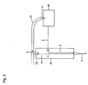
- Fig. 2 are highly schematized the fuel flow conditions in a high-pressure injector of a common rail injection system of a motor assembly, not shown.
- the supplied fuel is led up to the injection nozzle and parts of the unneeded fuel flow back. If the injection nozzle or the high-pressure injector 50 is defective or contaminated, a greatly increased amount of fuel flows back into the fuel tank 56 via a fuel return connection 52 of the high-pressure injector 50 and via a connected fuel return line 54.
- the reflux of the fuel is shown in the figures with the arrows R.
- a testing device 10 which has a flow rate measurement / display unit 12.
- the fuel return line 54 is released from the fuel return port 52.
- a connection between the fuel return connection 52 and the flow rate measurement / display unit 12 is established via a first flexible hose unit 20.
- the flow rate measurement / display unit 12 is connected to the return line 54 via a second flexible hose unit 22.
- the fuel return flow rate can now be determined and displayed via the flow rate measurement / display unit 12. Is the flow rate measurement before and after a cleaning process of the high-pressure injector 50, it can be determined on the basis of the display, whether the cleaning process was successful or whether another defect is present.
- the first hose unit 20 is released from the fuel return port 52 and the second hose unit 22 is released from the fuel return line 54. Subsequently, the fuel return line 54 is in turn connected via the fuel return port 52 to the high pressure injector 50.
- FIG Fig. 3 A structural embodiment of the flow rate measurement / display unit 12 is shown in FIG Fig. 3 shown schematically.
- This unit 12.1 is designed as a glass tube having top and bottom terminal units 33 for the first tube unit 20 and second tube unit 22, wherein within the unit 12.1 a floating body unit 14 is provided which is longitudinally displaceable within the unit 12 and depending on the flow rate different positions occupies. Furthermore, the unit 12.1 has a readable scale 16 by means of which the magnitude of the flow rate can be specified.
- This embodiment provides a commercially viable test device available that can be easily used and ensures a durable reliable function even under tough workshop conditions.
- Fig. 4 are shown in highly schematic form the four high-pressure injectors 50 of a 4-cylinder unit, which is supplied via an injection line E from the fuel tank 56 from fuel and the over the fuel return line 54 in the direction R superfluous fuel back to the fuel tank 56.
- Fig. 4a shows highly schematic without detailed representation of the necessary for the operation of the engine unit control, regulating and delivery units the normal operating condition.
- Fig. 4b the state is shown in which the left high pressure injector 50 is checked.
- the first flexible hose unit 20 is connected via the fuel return port 52 of the high-pressure injector 50, which in turn is connected to the flow rate measuring / display unit 12.
- the flow rate measuring / display unit 12 is in turn connected via a second flexible hose unit 22 to the return line 54, so that in total results in connection with the supply of the fuel in the injection direction E in turn a fuel circuit.
- the corresponding high-pressure injector 50 malfunctions, an increased amount of fuel compared with the normal operating state flows back, which is measured or indicated via the flow rate measuring / indicating unit 12.
- Fig. 2 illustrates the state that all four high pressure injectors 50 are tested by means of the flow rate measurement / display unit 12, each high pressure injector 50 being located in communication with the flow rate measurement / display unit 12 within a fuel flow loop.
Landscapes
- Engineering & Computer Science (AREA)
- Chemical & Material Sciences (AREA)
- Combustion & Propulsion (AREA)
- Mechanical Engineering (AREA)
- General Engineering & Computer Science (AREA)
- Accounting & Taxation (AREA)
- Business, Economics & Management (AREA)
- Finance (AREA)
- Physics & Mathematics (AREA)
- General Physics & Mathematics (AREA)
- Fuel-Injection Apparatus (AREA)
- Measuring Volume Flow (AREA)
- Examining Or Testing Airtightness (AREA)
Priority Applications (1)
| Application Number | Priority Date | Filing Date | Title |
|---|---|---|---|
| PL06705771T PL1907690T3 (pl) | 2005-07-28 | 2006-01-12 | Urządzenie kontrolne dla wtryskiwaczy wysokociśnieniowych układu wtrysku typu common rail i sposób kontroli wtryskiwaczy wysokociśnieniowych |
Applications Claiming Priority (2)
| Application Number | Priority Date | Filing Date | Title |
|---|---|---|---|
| DE202005011855U DE202005011855U1 (de) | 2005-07-28 | 2005-07-28 | Prüfeinrichtung für Hochdruck-Injektoren eines Common-Rail-Einspritzsystems |
| PCT/DE2006/000032 WO2007012298A1 (de) | 2005-07-28 | 2006-01-12 | Prüfeinrichtung für hochdruck-injektoren eines common-rail-einspritzsystems und verfahren zum prüfen von hochdruck-injektoren |
Publications (3)
| Publication Number | Publication Date |
|---|---|
| EP1907690A1 EP1907690A1 (de) | 2008-04-09 |
| EP1907690B1 EP1907690B1 (de) | 2011-03-30 |
| EP1907690B9 true EP1907690B9 (de) | 2011-09-07 |
Family
ID=35220353
Family Applications (1)
| Application Number | Title | Priority Date | Filing Date |
|---|---|---|---|
| EP06705771A Expired - Lifetime EP1907690B9 (de) | 2005-07-28 | 2006-01-12 | Prüfeinrichtung für hochdruck-injektoren eines common-rail-einspritzsystems und verfahren zum prüfen von hochdruck-injektoren |
Country Status (9)
| Country | Link |
|---|---|
| US (1) | US8047062B2 (pl) |
| EP (1) | EP1907690B9 (pl) |
| JP (1) | JP5094718B2 (pl) |
| AT (1) | ATE503925T1 (pl) |
| DE (3) | DE202005011855U1 (pl) |
| DK (1) | DK1907690T3 (pl) |
| ES (1) | ES2363790T3 (pl) |
| PL (1) | PL1907690T3 (pl) |
| WO (1) | WO2007012298A1 (pl) |
Families Citing this family (15)
| Publication number | Priority date | Publication date | Assignee | Title |
|---|---|---|---|---|
| US7878050B2 (en) * | 2008-05-09 | 2011-02-01 | Omar Cueto | Method and system for testing a fuel injector |
| US7975535B2 (en) * | 2008-05-09 | 2011-07-12 | Omar Cueto | Method and system for testing a fuel injector |
| US8641266B2 (en) * | 2008-06-27 | 2014-02-04 | William Ray McIntire | Horizontal-flow hydration apparatus |
| US8554454B2 (en) | 2010-05-20 | 2013-10-08 | Cummins Inc. | Service bay high pressure common rail injector performance test |
| CN101982737B (zh) * | 2010-10-09 | 2012-02-22 | 浙江大学 | 高压清洗机的综合检测装置 |
| CN102426108B (zh) * | 2011-08-25 | 2013-11-27 | 浙江大学 | 汽车散热器全闭环自动检测系统 |
| US20140224223A1 (en) * | 2013-02-08 | 2014-08-14 | Cummins Inc. | System and method for determining injected fuel quantity based on drain fuel flow |
| DE102014201671B3 (de) * | 2014-01-30 | 2015-05-13 | Continental Automotive Gmbh | Testen eines Kraftstoffinjektors |
| GB2533464A (en) * | 2015-10-20 | 2016-06-22 | Gm Global Tech Operations Llc | Method of operating a fuel injector of an internal combustion engine |
| CN105863920B (zh) * | 2016-03-31 | 2018-06-26 | 江苏大学 | 一种高压天然气喷射器标定装置及其方法 |
| RU2672992C1 (ru) * | 2017-06-07 | 2018-11-21 | федеральное государственное бюджетное образовательное учреждение высшего образования "Иркутский национальный исследовательский технический университет" (ФГБОУ ВО "ИРНИТУ") | Способ испытания приборов высокого давления топливной системы дизеля на работающем двигателе и устройство для его осуществления |
| DE102020113092A1 (de) | 2020-05-14 | 2021-11-18 | Bayerische Motoren Werke Aktiengesellschaft | Verfahren zum Überprüfen eines in einem Kraftfahrzeug angeordneten Einspritzsystems |
| CN111946520A (zh) * | 2020-08-25 | 2020-11-17 | 上海星融汽车科技有限公司 | 一种发动机共轨系统回油检测方法 |
| WO2022051563A1 (en) * | 2020-09-03 | 2022-03-10 | Arseneau Paul | Fuel injector testing machine |
| CN119844259B (zh) * | 2024-12-23 | 2025-11-14 | 中国船舶集团有限公司第七一一研究所 | 一种燃料喷射器油量测量方法及结构 |
Family Cites Families (16)
| Publication number | Priority date | Publication date | Assignee | Title |
|---|---|---|---|---|
| JPS5141558A (ja) * | 1974-10-04 | 1976-04-07 | Tokyo Keiso Kk | Shitsuryoryuryokei |
| JPS59159782U (ja) * | 1983-04-09 | 1984-10-26 | 株式会社明電舎 | 燃料噴射ポンプの噴射量計測装置 |
| US4788858A (en) * | 1987-08-04 | 1988-12-06 | Tif Instruments, Inc. | Fuel injector testing device and method |
| GB8823693D0 (en) * | 1988-10-08 | 1988-11-16 | Hartopp R | Injector cleaning apparatus |
| US4977873A (en) * | 1989-06-08 | 1990-12-18 | Clifford L. Elmore | Timing chamber ignition method and apparatus |
| US5117683A (en) * | 1990-02-06 | 1992-06-02 | Uis, Inc. | Method of measuring leakage in fuel injector system |
| US5020362A (en) * | 1990-06-15 | 1991-06-04 | Hickok Electrical Instrument Company | Fuel injection system tester |
| US5187974A (en) | 1991-08-29 | 1993-02-23 | Snap-On Tools Corporation | Vehicular pressure-testing apparatus |
| US5357792A (en) * | 1993-01-08 | 1994-10-25 | Getenby Alan D | Adaptor for testing fuel pressure in an operating engine |
| JPH07259688A (ja) * | 1994-03-24 | 1995-10-09 | Hino Motors Ltd | 直接噴射式ディーゼルエンジン用燃料噴射装置 |
| US5616837A (en) * | 1994-06-06 | 1997-04-01 | Ford Motor Company | Fuel line pressure test |
| US6234002B1 (en) * | 1997-09-05 | 2001-05-22 | David W. Sisney | Apparatus and methods for cleaning and testing fuel injectors |
| JP4022879B2 (ja) * | 2003-03-14 | 2007-12-19 | 株式会社デンソー | 内燃機関用燃料噴射システム |
| DE202004000922U1 (de) * | 2004-01-21 | 2004-03-18 | Lehnert, Friedrich | Prüfeinrichtung für Hochdruck-Injektoren eines Common-Rail-Einspritzsystems |
| US7228729B1 (en) * | 2006-07-26 | 2007-06-12 | Lincoln Industrial Corporation | Apparatus and method for testing fuel flow |
| US7587931B2 (en) * | 2008-01-29 | 2009-09-15 | Lincoln Industrial Corporation | Apparatus and method for testing fuel flow |
-
2005
- 2005-07-28 DE DE202005011855U patent/DE202005011855U1/de not_active Expired - Lifetime
-
2006
- 2006-01-12 WO PCT/DE2006/000032 patent/WO2007012298A1/de not_active Ceased
- 2006-01-12 DE DE112006002615T patent/DE112006002615A5/de not_active Withdrawn
- 2006-01-12 ES ES06705771T patent/ES2363790T3/es not_active Expired - Lifetime
- 2006-01-12 DK DK06705771.1T patent/DK1907690T3/da active
- 2006-01-12 AT AT06705771T patent/ATE503925T1/de active
- 2006-01-12 EP EP06705771A patent/EP1907690B9/de not_active Expired - Lifetime
- 2006-01-12 JP JP2008523110A patent/JP5094718B2/ja not_active Expired - Fee Related
- 2006-01-12 PL PL06705771T patent/PL1907690T3/pl unknown
- 2006-01-12 US US11/989,741 patent/US8047062B2/en not_active Expired - Lifetime
- 2006-01-12 DE DE502006009213T patent/DE502006009213D1/de not_active Expired - Lifetime
Also Published As
| Publication number | Publication date |
|---|---|
| EP1907690B1 (de) | 2011-03-30 |
| DK1907690T3 (da) | 2011-07-11 |
| US8047062B2 (en) | 2011-11-01 |
| US20090114035A1 (en) | 2009-05-07 |
| DE502006009213D1 (de) | 2011-05-12 |
| DE112006002615A5 (de) | 2008-06-26 |
| ES2363790T3 (es) | 2011-08-16 |
| ATE503925T1 (de) | 2011-04-15 |
| PL1907690T3 (pl) | 2011-09-30 |
| EP1907690A1 (de) | 2008-04-09 |
| DE202005011855U1 (de) | 2005-10-20 |
| JP5094718B2 (ja) | 2012-12-12 |
| JP2009503319A (ja) | 2009-01-29 |
| WO2007012298A1 (de) | 2007-02-01 |
Similar Documents
| Publication | Publication Date | Title |
|---|---|---|
| EP1907690B1 (de) | Prüfeinrichtung für hochdruck-injektoren eines common-rail-einspritzsystems und verfahren zum prüfen von hochdruck-injektoren | |
| DE68907549T2 (de) | Einspritzventilreinigungs-/-prüfvorrichtung. | |
| DE3309316A1 (de) | Reinigungsgeraet fuer eine kraftstoffeinspritzanlage | |
| DE102011075870B4 (de) | Verfahren zum Bewerten der Funktionsfähigkeit eines Kraftstoffeinspritzsystems einer Brennkraftmaschine | |
| DE10259797A1 (de) | Vorrichtung und Verfahren zum Erkennen von Fehlern in einem Kraftstoffeinspritzsystem | |
| DE10232356A1 (de) | Verfahren zur Steuerung von Injektoren eines Kraftstoffzumesssystems einer Brennkraftmaschine | |
| DE102012106020A1 (de) | Verfahren und System zum Bestimmen eines Ölstandes für ein Fahrzeug | |
| DE102011100029B4 (de) | Vorrichtung zum Messen eines Kraftstoffflusses und Kalibriervorrichtung dafür | |
| EP2126336A1 (de) | Testvorrichtung und verfahren zur überprüfung von einspritzkomponenten | |
| EP1645853A2 (de) | Verfahren zur Funktionsprüfung eines Füllstandssensors | |
| EP3234328B1 (de) | Verfahren und vorrichtung zur diagnose eines kraftstofffördersystems | |
| DE102007030003A1 (de) | Prüfverfahren zur Beurteilung von Kraftstoffinjektoren | |
| DE102019214754A1 (de) | Bestimmen der Einspritzmenge eines Kraftstoffinjektors | |
| DE102011108007A1 (de) | Verfahren zum Steuern des Systemdrucks in einem Kühlmittelkreislauf für eine Brennkraftmaschine | |
| DE102011101825A1 (de) | Kraftfahrzeugmotorsteuervorrichtung | |
| DE102010027677B4 (de) | Verfahren zur Erkennung eines Fehlverhaltens im Niederdrucksystem eines elektronisch geregelten Kraftstoffeinspritzsystems eines Verbrennungsmotors durch Evaluierung eines stimulierten Druckverhaltens | |
| DE102005028137A1 (de) | Verfahren zum Messen der Steuermenge eines Einspritzventils und ein Computerprogramm zur Durchführung eines solchen Verfahrens | |
| DE4301968A1 (de) | Fehlerdiagnoseverfahren und -vorrichtung bei Stereolambdaregelung | |
| DE102004037536A1 (de) | Prüfgerät und Prüfverfahren | |
| DE102008043411A1 (de) | Verfahren zum Injektormengenabgleich | |
| DE19711338B4 (de) | Verfahren zum Signalisieren einer Service-Maßnahme | |
| DE102008004278A1 (de) | Testgerät für Einspritzdüsen und Verfahren zum Testen von Einspritzdüsen | |
| DE102023118376A1 (de) | Kraftfahrzeug mit einem Verbrennungsmotor sowie Verfahren zum Ermitteln einer in einem Kraftfahrzeug verwendeten Kraftstoffart | |
| DE102004001692B4 (de) | Prüfverfahren und Prüfeinrichtung für einen Piezoaktor | |
| DE102015207452A1 (de) | Verfahren zur Prüfung einer Kraftstofffördereinrichtung, sowie ein Steuergerät und ein Werkstatt-Tester |
Legal Events
| Date | Code | Title | Description |
|---|---|---|---|
| PUAI | Public reference made under article 153(3) epc to a published international application that has entered the european phase |
Free format text: ORIGINAL CODE: 0009012 |
|
| 17P | Request for examination filed |
Effective date: 20080119 |
|
| AK | Designated contracting states |
Kind code of ref document: A1 Designated state(s): AT BE BG CH CY CZ DE DK EE ES FI FR GB GR HU IE IS IT LI LT LU LV MC NL PL PT RO SE SI SK TR |
|
| 17Q | First examination report despatched |
Effective date: 20091127 |
|
| GRAP | Despatch of communication of intention to grant a patent |
Free format text: ORIGINAL CODE: EPIDOSNIGR1 |
|
| GRAS | Grant fee paid |
Free format text: ORIGINAL CODE: EPIDOSNIGR3 |
|
| GRAA | (expected) grant |
Free format text: ORIGINAL CODE: 0009210 |
|
| AK | Designated contracting states |
Kind code of ref document: B1 Designated state(s): AT BE BG CH CY CZ DE DK EE ES FI FR GB GR HU IE IS IT LI LT LU LV MC NL PL PT RO SE SI SK TR |
|
| REG | Reference to a national code |
Ref country code: GB Ref legal event code: FG4D Free format text: NOT ENGLISH |
|
| REG | Reference to a national code |
Ref country code: CH Ref legal event code: EP |
|
| REG | Reference to a national code |
Ref country code: IE Ref legal event code: FG4D |
|
| REF | Corresponds to: |
Ref document number: 502006009213 Country of ref document: DE Date of ref document: 20110512 Kind code of ref document: P |
|
| REG | Reference to a national code |
Ref country code: DE Ref legal event code: R096 Ref document number: 502006009213 Country of ref document: DE Effective date: 20110512 |
|
| REG | Reference to a national code |
Ref country code: CH Ref legal event code: NV Representative=s name: ISLER & PEDRAZZINI AG |
|
| REG | Reference to a national code |
Ref country code: NL Ref legal event code: T3 |
|
| REG | Reference to a national code |
Ref country code: DK Ref legal event code: T3 |
|
| REG | Reference to a national code |
Ref country code: SE Ref legal event code: TRGR |
|
| PG25 | Lapsed in a contracting state [announced via postgrant information from national office to epo] |
Ref country code: LV Free format text: LAPSE BECAUSE OF FAILURE TO SUBMIT A TRANSLATION OF THE DESCRIPTION OR TO PAY THE FEE WITHIN THE PRESCRIBED TIME-LIMIT Effective date: 20110330 Ref country code: GR Free format text: LAPSE BECAUSE OF FAILURE TO SUBMIT A TRANSLATION OF THE DESCRIPTION OR TO PAY THE FEE WITHIN THE PRESCRIBED TIME-LIMIT Effective date: 20110701 Ref country code: LT Free format text: LAPSE BECAUSE OF FAILURE TO SUBMIT A TRANSLATION OF THE DESCRIPTION OR TO PAY THE FEE WITHIN THE PRESCRIBED TIME-LIMIT Effective date: 20110330 |
|
| REG | Reference to a national code |
Ref country code: ES Ref legal event code: FG2A Ref document number: 2363790 Country of ref document: ES Kind code of ref document: T3 Effective date: 20110816 |
|
| LTIE | Lt: invalidation of european patent or patent extension |
Effective date: 20110330 |
|
| PG25 | Lapsed in a contracting state [announced via postgrant information from national office to epo] |
Ref country code: SI Free format text: LAPSE BECAUSE OF FAILURE TO SUBMIT A TRANSLATION OF THE DESCRIPTION OR TO PAY THE FEE WITHIN THE PRESCRIBED TIME-LIMIT Effective date: 20110330 Ref country code: CY Free format text: LAPSE BECAUSE OF FAILURE TO SUBMIT A TRANSLATION OF THE DESCRIPTION OR TO PAY THE FEE WITHIN THE PRESCRIBED TIME-LIMIT Effective date: 20110330 Ref country code: FI Free format text: LAPSE BECAUSE OF FAILURE TO SUBMIT A TRANSLATION OF THE DESCRIPTION OR TO PAY THE FEE WITHIN THE PRESCRIBED TIME-LIMIT Effective date: 20110330 |
|
| REG | Reference to a national code |
Ref country code: PL Ref legal event code: T3 |
|
| REG | Reference to a national code |
Ref country code: IE Ref legal event code: FD4D |
|
| PG25 | Lapsed in a contracting state [announced via postgrant information from national office to epo] |
Ref country code: EE Free format text: LAPSE BECAUSE OF FAILURE TO SUBMIT A TRANSLATION OF THE DESCRIPTION OR TO PAY THE FEE WITHIN THE PRESCRIBED TIME-LIMIT Effective date: 20110330 Ref country code: PT Free format text: LAPSE BECAUSE OF FAILURE TO SUBMIT A TRANSLATION OF THE DESCRIPTION OR TO PAY THE FEE WITHIN THE PRESCRIBED TIME-LIMIT Effective date: 20110801 |
|
| PG25 | Lapsed in a contracting state [announced via postgrant information from national office to epo] |
Ref country code: RO Free format text: LAPSE BECAUSE OF FAILURE TO SUBMIT A TRANSLATION OF THE DESCRIPTION OR TO PAY THE FEE WITHIN THE PRESCRIBED TIME-LIMIT Effective date: 20110330 Ref country code: IS Free format text: LAPSE BECAUSE OF FAILURE TO SUBMIT A TRANSLATION OF THE DESCRIPTION OR TO PAY THE FEE WITHIN THE PRESCRIBED TIME-LIMIT Effective date: 20110730 Ref country code: SK Free format text: LAPSE BECAUSE OF FAILURE TO SUBMIT A TRANSLATION OF THE DESCRIPTION OR TO PAY THE FEE WITHIN THE PRESCRIBED TIME-LIMIT Effective date: 20110330 |
|
| PLBI | Opposition filed |
Free format text: ORIGINAL CODE: 0009260 |
|
| PG25 | Lapsed in a contracting state [announced via postgrant information from national office to epo] |
Ref country code: IE Free format text: LAPSE BECAUSE OF FAILURE TO SUBMIT A TRANSLATION OF THE DESCRIPTION OR TO PAY THE FEE WITHIN THE PRESCRIBED TIME-LIMIT Effective date: 20110330 |
|
| 26 | Opposition filed |
Opponent name: AUTOTESTGERAETE LEITENBERGER GMBH Effective date: 20111228 |
|
| PLAX | Notice of opposition and request to file observation + time limit sent |
Free format text: ORIGINAL CODE: EPIDOSNOBS2 |
|
| PLBP | Opposition withdrawn |
Free format text: ORIGINAL CODE: 0009264 |
|
| PLBB | Reply of patent proprietor to notice(s) of opposition received |
Free format text: ORIGINAL CODE: EPIDOSNOBS3 |
|
| REG | Reference to a national code |
Ref country code: DE Ref legal event code: R026 Ref document number: 502006009213 Country of ref document: DE Effective date: 20111228 |
|
| PG25 | Lapsed in a contracting state [announced via postgrant information from national office to epo] |
Ref country code: MC Free format text: LAPSE BECAUSE OF NON-PAYMENT OF DUE FEES Effective date: 20120131 |
|
| PLBD | Termination of opposition procedure: decision despatched |
Free format text: ORIGINAL CODE: EPIDOSNOPC1 |
|
| PLBM | Termination of opposition procedure: date of legal effect published |
Free format text: ORIGINAL CODE: 0009276 |
|
| STAA | Information on the status of an ep patent application or granted ep patent |
Free format text: STATUS: OPPOSITION PROCEDURE CLOSED |
|
| 27C | Opposition proceedings terminated |
Effective date: 20121213 |
|
| PG25 | Lapsed in a contracting state [announced via postgrant information from national office to epo] |
Ref country code: BG Free format text: LAPSE BECAUSE OF FAILURE TO SUBMIT A TRANSLATION OF THE DESCRIPTION OR TO PAY THE FEE WITHIN THE PRESCRIBED TIME-LIMIT Effective date: 20110630 |
|
| PG25 | Lapsed in a contracting state [announced via postgrant information from national office to epo] |
Ref country code: TR Free format text: LAPSE BECAUSE OF FAILURE TO SUBMIT A TRANSLATION OF THE DESCRIPTION OR TO PAY THE FEE WITHIN THE PRESCRIBED TIME-LIMIT Effective date: 20110330 |
|
| PG25 | Lapsed in a contracting state [announced via postgrant information from national office to epo] |
Ref country code: LU Free format text: LAPSE BECAUSE OF NON-PAYMENT OF DUE FEES Effective date: 20120112 |
|
| PG25 | Lapsed in a contracting state [announced via postgrant information from national office to epo] |
Ref country code: HU Free format text: LAPSE BECAUSE OF FAILURE TO SUBMIT A TRANSLATION OF THE DESCRIPTION OR TO PAY THE FEE WITHIN THE PRESCRIBED TIME-LIMIT Effective date: 20060112 |
|
| REG | Reference to a national code |
Ref country code: FR Ref legal event code: PLFP Year of fee payment: 11 |
|
| REG | Reference to a national code |
Ref country code: FR Ref legal event code: PLFP Year of fee payment: 12 |
|
| REG | Reference to a national code |
Ref country code: FR Ref legal event code: PLFP Year of fee payment: 13 |
|
| REG | Reference to a national code |
Ref country code: DE Ref legal event code: R082 Ref document number: 502006009213 Country of ref document: DE Representative=s name: MUELLER, CLEMENS & HACH, DE Ref country code: DE Ref legal event code: R081 Ref document number: 502006009213 Country of ref document: DE Owner name: LEHNERT, TOBIAS, DE Free format text: FORMER OWNER: LEHNERT, FRIEDRICH, 74196 NEUENSTADT, DE |
|
| P01 | Opt-out of the competence of the unified patent court (upc) registered |
Effective date: 20230516 |
|
| REG | Reference to a national code |
Ref country code: DE Ref legal event code: R082 Ref document number: 502006009213 Country of ref document: DE Representative=s name: GLEIM PETRI PATENT- UND RECHTSANWALTSPARTNERSC, DE |
|
| PGFP | Annual fee paid to national office [announced via postgrant information from national office to epo] |
Ref country code: NL Payment date: 20240123 Year of fee payment: 19 |
|
| PGFP | Annual fee paid to national office [announced via postgrant information from national office to epo] |
Ref country code: ES Payment date: 20240216 Year of fee payment: 19 |
|
| PGFP | Annual fee paid to national office [announced via postgrant information from national office to epo] |
Ref country code: AT Payment date: 20240118 Year of fee payment: 19 |
|
| PGFP | Annual fee paid to national office [announced via postgrant information from national office to epo] |
Ref country code: CZ Payment date: 20231229 Year of fee payment: 19 Ref country code: GB Payment date: 20240124 Year of fee payment: 19 Ref country code: CH Payment date: 20240202 Year of fee payment: 19 |
|
| PGFP | Annual fee paid to national office [announced via postgrant information from national office to epo] |
Ref country code: SE Payment date: 20240123 Year of fee payment: 19 Ref country code: PL Payment date: 20240102 Year of fee payment: 19 Ref country code: IT Payment date: 20240131 Year of fee payment: 19 Ref country code: FR Payment date: 20240123 Year of fee payment: 19 Ref country code: DK Payment date: 20240123 Year of fee payment: 19 Ref country code: BE Payment date: 20240122 Year of fee payment: 19 |
|
| PGFP | Annual fee paid to national office [announced via postgrant information from national office to epo] |
Ref country code: DE Payment date: 20241218 Year of fee payment: 20 |
|
| REG | Reference to a national code |
Ref country code: DK Ref legal event code: EBP Effective date: 20250131 |
|
| REG | Reference to a national code |
Ref country code: CH Ref legal event code: PL |
|
| REG | Reference to a national code |
Ref country code: SE Ref legal event code: EUG |
|
| REG | Reference to a national code |
Ref country code: NL Ref legal event code: MM Effective date: 20250201 |
|
| REG | Reference to a national code |
Ref country code: AT Ref legal event code: MM01 Ref document number: 503925 Country of ref document: AT Kind code of ref document: T Effective date: 20250112 |
|
| GBPC | Gb: european patent ceased through non-payment of renewal fee |
Effective date: 20250112 |
|
| PG25 | Lapsed in a contracting state [announced via postgrant information from national office to epo] |
Ref country code: NL Free format text: LAPSE BECAUSE OF NON-PAYMENT OF DUE FEES Effective date: 20250201 |
|
| PG25 | Lapsed in a contracting state [announced via postgrant information from national office to epo] |
Ref country code: BE Free format text: LAPSE BECAUSE OF NON-PAYMENT OF DUE FEES Effective date: 20250131 Ref country code: GB Free format text: LAPSE BECAUSE OF NON-PAYMENT OF DUE FEES Effective date: 20250112 |
|
| PG25 | Lapsed in a contracting state [announced via postgrant information from national office to epo] |
Ref country code: AT Free format text: LAPSE BECAUSE OF NON-PAYMENT OF DUE FEES Effective date: 20250112 Ref country code: FR Free format text: LAPSE BECAUSE OF NON-PAYMENT OF DUE FEES Effective date: 20250131 |
|
| PG25 | Lapsed in a contracting state [announced via postgrant information from national office to epo] |
Ref country code: CH Free format text: LAPSE BECAUSE OF NON-PAYMENT OF DUE FEES Effective date: 20250131 |
|
| PG25 | Lapsed in a contracting state [announced via postgrant information from national office to epo] |
Ref country code: CZ Free format text: LAPSE BECAUSE OF NON-PAYMENT OF DUE FEES Effective date: 20250112 |
|
| REG | Reference to a national code |
Ref country code: BE Ref legal event code: MM Effective date: 20250131 |
|
| REG | Reference to a national code |
Ref country code: DE Ref legal event code: R071 Ref document number: 502006009213 Country of ref document: DE |
|
| PG25 | Lapsed in a contracting state [announced via postgrant information from national office to epo] |
Ref country code: DK Free format text: LAPSE BECAUSE OF NON-PAYMENT OF DUE FEES Effective date: 20250131 |
|
| PG25 | Lapsed in a contracting state [announced via postgrant information from national office to epo] |
Ref country code: IT Free format text: LAPSE BECAUSE OF NON-PAYMENT OF DUE FEES Effective date: 20250112 |
|
| REG | Reference to a national code |
Ref country code: ES Ref legal event code: FD2A Effective date: 20260227 |
|
| PG25 | Lapsed in a contracting state [announced via postgrant information from national office to epo] |
Ref country code: ES Free format text: LAPSE BECAUSE OF NON-PAYMENT OF DUE FEES Effective date: 20250113 |