EP1904666B1 - Bauteil für das einsatzgiessen, zylinderblock und verfahren zur herstellung von zylinderlaufbuchse - Google Patents
Bauteil für das einsatzgiessen, zylinderblock und verfahren zur herstellung von zylinderlaufbuchse Download PDFInfo
- Publication number
- EP1904666B1 EP1904666B1 EP06781033A EP06781033A EP1904666B1 EP 1904666 B1 EP1904666 B1 EP 1904666B1 EP 06781033 A EP06781033 A EP 06781033A EP 06781033 A EP06781033 A EP 06781033A EP 1904666 B1 EP1904666 B1 EP 1904666B1
- Authority
- EP
- European Patent Office
- Prior art keywords
- cylinder liner
- circumferential surface
- outer circumferential
- projections
- coating layer
- Prior art date
- Legal status (The legal status is an assumption and is not a legal conclusion. Google has not performed a legal analysis and makes no representation as to the accuracy of the status listed.)
- Active
Links
- 238000005266 casting Methods 0.000 title claims description 57
- 238000000034 method Methods 0.000 title claims description 26
- 238000004519 manufacturing process Methods 0.000 title claims description 11
- 229910052751 metal Inorganic materials 0.000 claims description 111
- 239000002184 metal Substances 0.000 claims description 111
- 239000011247 coating layer Substances 0.000 claims description 71
- 238000010586 diagram Methods 0.000 claims description 61
- 239000000463 material Substances 0.000 claims description 26
- 239000007769 metal material Substances 0.000 claims description 20
- 238000010288 cold spraying Methods 0.000 claims description 16
- 229910000838 Al alloy Inorganic materials 0.000 claims description 13
- 229910052782 aluminium Inorganic materials 0.000 claims description 11
- XAGFODPZIPBFFR-UHFFFAOYSA-N aluminium Chemical compound [Al] XAGFODPZIPBFFR-UHFFFAOYSA-N 0.000 claims description 11
- 238000002844 melting Methods 0.000 claims description 11
- 230000008018 melting Effects 0.000 claims description 11
- 238000002485 combustion reaction Methods 0.000 claims description 7
- 239000010949 copper Substances 0.000 claims description 5
- RYGMFSIKBFXOCR-UHFFFAOYSA-N Copper Chemical compound [Cu] RYGMFSIKBFXOCR-UHFFFAOYSA-N 0.000 claims description 4
- 229910000881 Cu alloy Inorganic materials 0.000 claims description 4
- 229910052802 copper Inorganic materials 0.000 claims description 4
- 229910000978 Pb alloy Inorganic materials 0.000 claims description 3
- 229910001245 Sb alloy Inorganic materials 0.000 claims description 3
- 229910001128 Sn alloy Inorganic materials 0.000 claims description 3
- ATJFFYVFTNAWJD-UHFFFAOYSA-N Tin Chemical compound [Sn] ATJFFYVFTNAWJD-UHFFFAOYSA-N 0.000 claims description 3
- HCHKCACWOHOZIP-UHFFFAOYSA-N Zinc Chemical compound [Zn] HCHKCACWOHOZIP-UHFFFAOYSA-N 0.000 claims description 3
- 229910001297 Zn alloy Inorganic materials 0.000 claims description 3
- 229910052787 antimony Inorganic materials 0.000 claims description 3
- 239000002140 antimony alloy Substances 0.000 claims description 3
- WATWJIUSRGPENY-UHFFFAOYSA-N antimony atom Chemical compound [Sb] WATWJIUSRGPENY-UHFFFAOYSA-N 0.000 claims description 3
- 239000011701 zinc Substances 0.000 claims description 3
- 229910052725 zinc Inorganic materials 0.000 claims description 3
- 239000010410 layer Substances 0.000 description 29
- 238000005259 measurement Methods 0.000 description 18
- 230000008901 benefit Effects 0.000 description 10
- 238000011068 loading method Methods 0.000 description 7
- 230000008569 process Effects 0.000 description 6
- XLYOFNOQVPJJNP-UHFFFAOYSA-N water Substances O XLYOFNOQVPJJNP-UHFFFAOYSA-N 0.000 description 6
- 238000001816 cooling Methods 0.000 description 5
- 239000011819 refractory material Substances 0.000 description 5
- 238000005422 blasting Methods 0.000 description 4
- 238000012545 processing Methods 0.000 description 4
- 239000004094 surface-active agent Substances 0.000 description 4
- 229910001018 Cast iron Inorganic materials 0.000 description 3
- QVGXLLKOCUKJST-UHFFFAOYSA-N atomic oxygen Chemical compound [O] QVGXLLKOCUKJST-UHFFFAOYSA-N 0.000 description 3
- 239000011230 binding agent Substances 0.000 description 3
- 230000015572 biosynthetic process Effects 0.000 description 3
- 238000009826 distribution Methods 0.000 description 3
- 239000000203 mixture Substances 0.000 description 3
- 239000001301 oxygen Substances 0.000 description 3
- 229910052760 oxygen Inorganic materials 0.000 description 3
- 239000002245 particle Substances 0.000 description 3
- 238000005480 shot peening Methods 0.000 description 3
- 239000007921 spray Substances 0.000 description 3
- 238000005507 spraying Methods 0.000 description 3
- 239000002344 surface layer Substances 0.000 description 3
- XEEYBQQBJWHFJM-UHFFFAOYSA-N Iron Chemical group [Fe] XEEYBQQBJWHFJM-UHFFFAOYSA-N 0.000 description 2
- 230000004913 activation Effects 0.000 description 2
- 229910045601 alloy Inorganic materials 0.000 description 2
- 239000000956 alloy Substances 0.000 description 2
- 230000000694 effects Effects 0.000 description 2
- 229910001234 light alloy Inorganic materials 0.000 description 2
- 239000000843 powder Substances 0.000 description 2
- 230000009467 reduction Effects 0.000 description 2
- 238000007788 roughening Methods 0.000 description 2
- 239000000725 suspension Substances 0.000 description 2
- 238000012360 testing method Methods 0.000 description 2
- 238000013329 compounding Methods 0.000 description 1
- 230000002349 favourable effect Effects 0.000 description 1
- 230000004927 fusion Effects 0.000 description 1
- 239000011261 inert gas Substances 0.000 description 1
- 229910052742 iron Inorganic materials 0.000 description 1
- 230000001678 irradiating effect Effects 0.000 description 1
- 230000007246 mechanism Effects 0.000 description 1
- 239000000155 melt Substances 0.000 description 1
- 239000002923 metal particle Substances 0.000 description 1
- 238000007750 plasma spraying Methods 0.000 description 1
- 239000007787 solid Substances 0.000 description 1
- 238000000859 sublimation Methods 0.000 description 1
- 230000008022 sublimation Effects 0.000 description 1
- 239000000126 substance Substances 0.000 description 1
- 238000004381 surface treatment Methods 0.000 description 1
Images


Classifications
-
- B—PERFORMING OPERATIONS; TRANSPORTING
- B22—CASTING; POWDER METALLURGY
- B22D—CASTING OF METALS; CASTING OF OTHER SUBSTANCES BY THE SAME PROCESSES OR DEVICES
- B22D19/00—Casting in, on, or around objects which form part of the product
-
- C—CHEMISTRY; METALLURGY
- C23—COATING METALLIC MATERIAL; COATING MATERIAL WITH METALLIC MATERIAL; CHEMICAL SURFACE TREATMENT; DIFFUSION TREATMENT OF METALLIC MATERIAL; COATING BY VACUUM EVAPORATION, BY SPUTTERING, BY ION IMPLANTATION OR BY CHEMICAL VAPOUR DEPOSITION, IN GENERAL; INHIBITING CORROSION OF METALLIC MATERIAL OR INCRUSTATION IN GENERAL
- C23C—COATING METALLIC MATERIAL; COATING MATERIAL WITH METALLIC MATERIAL; SURFACE TREATMENT OF METALLIC MATERIAL BY DIFFUSION INTO THE SURFACE, BY CHEMICAL CONVERSION OR SUBSTITUTION; COATING BY VACUUM EVAPORATION, BY SPUTTERING, BY ION IMPLANTATION OR BY CHEMICAL VAPOUR DEPOSITION, IN GENERAL
- C23C24/00—Coating starting from inorganic powder
- C23C24/02—Coating starting from inorganic powder by application of pressure only
- C23C24/04—Impact or kinetic deposition of particles
-
- B—PERFORMING OPERATIONS; TRANSPORTING
- B22—CASTING; POWDER METALLURGY
- B22D—CASTING OF METALS; CASTING OF OTHER SUBSTANCES BY THE SAME PROCESSES OR DEVICES
- B22D19/00—Casting in, on, or around objects which form part of the product
- B22D19/0009—Cylinders, pistons
-
- B—PERFORMING OPERATIONS; TRANSPORTING
- B22—CASTING; POWDER METALLURGY
- B22D—CASTING OF METALS; CASTING OF OTHER SUBSTANCES BY THE SAME PROCESSES OR DEVICES
- B22D19/00—Casting in, on, or around objects which form part of the product
- B22D19/0081—Casting in, on, or around objects which form part of the product pretreatment of the insert, e.g. for enhancing the bonding between insert and surrounding cast metal
-
- C—CHEMISTRY; METALLURGY
- C23—COATING METALLIC MATERIAL; COATING MATERIAL WITH METALLIC MATERIAL; CHEMICAL SURFACE TREATMENT; DIFFUSION TREATMENT OF METALLIC MATERIAL; COATING BY VACUUM EVAPORATION, BY SPUTTERING, BY ION IMPLANTATION OR BY CHEMICAL VAPOUR DEPOSITION, IN GENERAL; INHIBITING CORROSION OF METALLIC MATERIAL OR INCRUSTATION IN GENERAL
- C23C—COATING METALLIC MATERIAL; COATING MATERIAL WITH METALLIC MATERIAL; SURFACE TREATMENT OF METALLIC MATERIAL BY DIFFUSION INTO THE SURFACE, BY CHEMICAL CONVERSION OR SUBSTITUTION; COATING BY VACUUM EVAPORATION, BY SPUTTERING, BY ION IMPLANTATION OR BY CHEMICAL VAPOUR DEPOSITION, IN GENERAL
- C23C28/00—Coating for obtaining at least two superposed coatings either by methods not provided for in a single one of groups C23C2/00 - C23C26/00 or by combinations of methods provided for in subclasses C23C and C25C or C25D
- C23C28/02—Coating for obtaining at least two superposed coatings either by methods not provided for in a single one of groups C23C2/00 - C23C26/00 or by combinations of methods provided for in subclasses C23C and C25C or C25D only coatings only including layers of metallic material
- C23C28/021—Coating for obtaining at least two superposed coatings either by methods not provided for in a single one of groups C23C2/00 - C23C26/00 or by combinations of methods provided for in subclasses C23C and C25C or C25D only coatings only including layers of metallic material including at least one metal alloy layer
-
- F—MECHANICAL ENGINEERING; LIGHTING; HEATING; WEAPONS; BLASTING
- F02—COMBUSTION ENGINES; HOT-GAS OR COMBUSTION-PRODUCT ENGINE PLANTS
- F02F—CYLINDERS, PISTONS OR CASINGS, FOR COMBUSTION ENGINES; ARRANGEMENTS OF SEALINGS IN COMBUSTION ENGINES
- F02F1/00—Cylinders; Cylinder heads
-
- F—MECHANICAL ENGINEERING; LIGHTING; HEATING; WEAPONS; BLASTING
- F02—COMBUSTION ENGINES; HOT-GAS OR COMBUSTION-PRODUCT ENGINE PLANTS
- F02F—CYLINDERS, PISTONS OR CASINGS, FOR COMBUSTION ENGINES; ARRANGEMENTS OF SEALINGS IN COMBUSTION ENGINES
- F02F1/00—Cylinders; Cylinder heads
- F02F1/004—Cylinder liners
-
- Y—GENERAL TAGGING OF NEW TECHNOLOGICAL DEVELOPMENTS; GENERAL TAGGING OF CROSS-SECTIONAL TECHNOLOGIES SPANNING OVER SEVERAL SECTIONS OF THE IPC; TECHNICAL SUBJECTS COVERED BY FORMER USPC CROSS-REFERENCE ART COLLECTIONS [XRACs] AND DIGESTS
- Y10—TECHNICAL SUBJECTS COVERED BY FORMER USPC
- Y10T—TECHNICAL SUBJECTS COVERED BY FORMER US CLASSIFICATION
- Y10T29/00—Metal working
- Y10T29/49—Method of mechanical manufacture
- Y10T29/49229—Prime mover or fluid pump making
- Y10T29/4927—Cylinder, cylinder head or engine valve sleeve making
- Y10T29/49272—Cylinder, cylinder head or engine valve sleeve making with liner, coating, or sleeve
Definitions
- the present invention relates to a component for insert casting, which is enveloped in a casting metal through insert casting, and a cylinder block having such an insert casting component as a cylinder liner.
- Components for insert casting include, for example, cylinder liners, which are integrated with a cylinder block through insert casting to form cylinder bores.
- cylinder liners which are integrated with a cylinder block through insert casting to form cylinder bores.
- the outer circumferential surface of such a component which contacts the casting material used in insert casting, needs to have a great bond strength with the cylinder block.
- Japanese Laid-Open Utility Model Publication No. 53-163405 discloses a surface layer on a cylinder liner outer circumferential surface onto which granulated metal is sprayed such that the granulated metal irregularly collects on the surface and forms asperities. During casting, molten metal flows into the recesses of the asperities to produce anchor effect, and a great bond strength is produced.
- an activation layer made of an aluminum alloy is formed as a surface layer in a top dead center region and a bottom dead center region of a cylinder liner outer circumferential surface, so that the activation layer establishes metallic bonding with a crankcase (for example, Japanese Laid Open Patent Publication No. 2003-120414 ).
- the sprayed layer on the cylinder liner outer circumferential surface is formed by causing metal particles, which have been melted at a high temperature, to collide with the cylinder liner. Therefore, an oxide film is formed on the surface of the sprayed layer, and oxides exist in the sprayed layer. As a result, the thermal conductivity of the metal after the spraying process becomes less than that of the same metal before the process. This configuration does not improve the cooling performance to a satisfactory level.
- Japanese Laid-Open Patent Publication No. 2003-53508 a film of a low melting point material is formed on a cylinder liner outer circumferential surface.
- thermal effect causes fusion, so that a favorable metallic bonding is produced.
- the film is formed in a high temperature molten state such as spraying.
- this configuration does not guarantee a satisfactory level of cooling performance.
- shot peening is used.
- shot peening is a surface treatment method and cannot form a complete film.
- a component for insert casting having an outer circumferential surface that is enveloped in a casting metal through insert casting is provided.
- a metal coating layer is formed on the outer circumferential surface through a cold spraying method.
- a cylinder liner bonded to a cylinder block of an internal combustion engine includes a cylinder liner body and a metal coating layer.
- the cylinder liner body has an outer circumferential surface that is enveloped, through insert casting, in a casting metal for forming the cylinder block.
- the metal coating layer is formed on the outer circumferential surface through a cold spraying method.
- a cylinder block of an internal combustion engine is provided.
- the cylinder block is formed by casting a metal.
- a cylinder liner is enveloped in the metal through insert casting so that the cylinder liner is bonded to the cylinder block.
- An outer circumferential surface of the cylinder liner, which is bonded to the cylinder block, has a metal coating layer formed through a cold spraying method.
- a method for manufacturing a cylinder liner that is, through insert casting, enveloped in a block material forming a cylinder block of an internal combustion engine is provided.
- the method includes: preparing a cylindrical cylinder liner body; and forming a metal coating layer on an outer circumferential surface of the cylinder liner body through a cold spraying method.
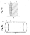
- FIG. 1A is a perspective view.a cylinder liner 2 according to the present invention.
- Fig. 1B is a partially enlarged cross-sectional view of the cylinder liner 2.
- Fig. 2A is a partially perspective view of a cylinder block 4 in which the cylinder liner 2 is enveloped through insert casting.
- Fig. 2B is a partially enlarged cross-sectional view of the cylinder block 4.
- a water jacket 4a is formed about the cylinder liner 2, which is enveloped in the cylinder block 4.
- a body 2a of the cylinder liner 2 shown in Figs. 1A and 1B is a cylindrical body made of cast iron.
- the cylinder liner 2 is formed by forming a metal coating layer 8 on an outer circumferential surface 6 of the cylinder liner body 2a (hereafter referred to as outer circumferential surface).
- the metal coating layer 8 metallurgically bonds the cylinder liner 2 with the cylinder block 4 during casting.
- the composition of the iron cast is preferably set as follows.
- T.C 2.9 to 3.7% by mass Si: 1.6 to 2.8% by mass
- Mn 0.5 to 1.0% by mass
- P 0.05 to 0.4% by mass
- a highly thermal conductive metal material is used as the metal material for forming the metal coating layer 8.
- metal material for forming the metal coating layer 8 aluminum, an aluminum alloy, copper, or a copper alloy may be used.
- the outer circumferential surface 6 is roughened in advance by a roughening device (in this embodiment, a blasting device or a water jet device).
- a roughening device in this embodiment, a blasting device or a water jet device.
- the same material as the block material may be pulverized and used for the cold spraying.
- the cylinder block 4 is formed by enveloping the cylinder liner 2 through insert casting. Specifically, an outer circumferential surface 2c of the cylinder liner 2, on which the metal coating layer 8 is formed, is enveloped by the block material.
- a light alloy is used as the casting material used as the block material. Taking reduction of weight and costs into consideration, aluminum or an aluminum alloy is used as the block material.
- the aluminum alloy for example, an alloy specified in Japanese Industrial Standard (JIS) ADC10 (related United States standard, ASTM A380.0) or an alloy specified in JIS ADC12 (related United States standard, ASTM A383.0) may be used.
- the cylinder liner 2 shown in Fig. 1A is placed in a mold. Then, molten aluminum or aluminum alloy is poured into the mold. The cylinder block 4 is produced in which the entire outer circumference of the metal coating layer 8 is enveloped in aluminum or an aluminum alloy.
- molten metal 10 contacts and heats the metal coating layer 8 on the outer circumferential surface 6. Since the metal coating layer 8 is formed through cold spraying as described above, few oxide layers exist on the surface of the metal coating layer 8, that is., on the outer circumferential surface 2c of the cylinder liner 2, and the molten metal 10 is solidified while sufficiently adhering to the metal coating layer 8. The casting of the cylinder block 4 is thus completed.
- the first embodiment described above has the following advantages.
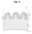
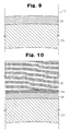
- Fig. 4 is a partially cross-sectional view of a cylinder liner according to a second embodiment.
- a body 12a of the cylinder liner 12 is made of cast iron having the same composition as that of the first embodiment, a plurality of projections 17 each having a constricted shape are integrally formed on an outer circumferential surface 16.
- Each projection 17 is formed in the following manner.
- a metal coating layer 18 is formed on the outer circumferential surface 16.
- the metal coating layer 18 metallurgically bonds with a block material.
- the metal coating layer 18 is the same as the metal coating layer of the first embodiment. That is, a highly thermal conductive metal material is used as the metal material for forming the metal coating layer 18.
- a highly thermal conductive metal material is used as the metal material for forming the metal coating layer 18.
- aluminum, an aluminum alloy, copper, or a copper alloy may be used.
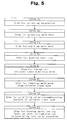
- the production of the cylinder liner 12 is executed according to the procedure of [step A] to [step H] shown in Fig. 5 .
- Suspension C4 is prepared by compounding refractory material C1, binder C2, and water C3 in predetermined ratios.
- possible ranges for the loadings of the refractory material C1, the binder C2, and water C3 and possible ranges for the average particle size of the refractory material C1 are set as follows. Loading of the refractory material C1: 8 to 30% by mass Loading of the binder C2: 2 to 10% by mass Loading of water C3: 60 to 90% by mass Average particle size of the refractory material C1: 0.02 to 0.1 mm
- a predetermined amount of surfactant C5 is added to the suspension C4 to obtain mold wash C6.
- a possible range of the loading of the surfactant C5 is set as follows. Loading of the surfactant C5: 0.005% by mass ⁇ X ⁇ 0.1% by mass (X represents the loading)
- the mold wash C6 is applied through spraying on an inner circumferential surface Pi of a mold P, which has been heated to a prescribed temperature and is being rotated. At this time, the mold wash C6 is applied such that a layer of the mold wash C6 (mold wash layer C7) of a uniform thickness is formed on the entire inner circumferential surface Pi.
- a possible range for the thickness of the mold wash layer C7 is set as follows.
- Thickness of the mold wash layer C7 0.5 to 1.5 mm
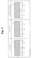
- Fig. 7 shows one example of the order of steps for forming a hole with a constriction in the mold wash layer C7.
- the surfactant C5 acts on a bubble D1 in the mold wash layer C7, so that a recess D2 is formed to extend toward the inner circumference of the mold wash layer C7.
- the recess D2 reaches the inner circumferential surface Pi of the mold P, so that a hole D3 having a constricted shape is formed in the mold wash layer C7.
- the cylinder liner body 12a is taken out of the mold P with the mold wash layer C7.
- the mold wash C7 is removed from the outer circumferential surface 16.
- a roughening device a blasting device such as the blasting device Ma or a waterjet device
- the outer circumferential surface 16 is roughened.
- the outer circumferential surface 16 is coated with powder of a high thermal conductive metal material as in the first embodiment. This forms the metal coating layer 18 on the outer circumferential surface 16 to cover the projections 17.
- possible ranges for a first area ratio S1 and a second area ratio S2 of the projections 17 on the cylinder liner body 12a are set as follows.
- the first area ratio S1 corresponds to the cross-sectional area of the projections 17 per unit area in a plane the height of which is 0:4 mm from the base surface 17e (the distance in the height direction with reference to the base surface 17e).
- the second area ratio S2 corresponds to the cross-sectional area of the projections 17 per unit area in a plane the height of which is 0.2 mm from the base surface 17e (the distance in the height direction with reference to the base surface 17e).
- the area ratios S1, S2 are obtained based on a contour diagrams ( Figs. 11 and 12 , discussed below) of the projection 17 obtained by using a three-dimensional laser measuring device.
- the height and the distribution density of the projection 17 are determined by the depth and the distribution density of the holes D3 of the mold wash layer C7 formed in step C. Specifically, the mold wash layer C7 is formed such that the height of the projections 17 is 0.5 mm to 1.5 mm, and the distribution density of the projections 17, or the number of the projections 17 per cm 2 of the outer circumferential surface, is five to sixty.
- the cylinder block is produced by placing the cylinder liner 12 shown in Fig. 4 in a mold, and pouring molten metal 20 of a block material into the mold so that the outer circumferential surface 16 is enveloped in the molten metal 20.
- the block material is the same as that described in the first embodiment 1, and the same light alloy is used.
- the molten metal 20 is solidified while sufficiently adhering to the metal coating layer 18 through the mechanism explained in the first embodiment.
- the second embodiment has the following advantages.
- the projections 17 having a constricted shape further increase the thermal conductivity from the cylinder liner body 12a to the cylinder block, which improves the cooling performance of the cylinder bore 12b.
- a cylinder liner body 22a which is the same as the cylinder liner body of the first embodiment is used.
- a metal coating layer 28 is formed on the cylinder liner body 22a with a low melting point metal powder material by using a cold spraying apparatus, thereby producing a cylinder liner 22.
- the low melting point metal material may be zinc, a zinc alloy, tin, a tin alloy, lead, a lead alloy, antimony, or an antimony alloy.
- the metal coating layer 28 formed by cold spraying contains few oxide films and oxide layers on the surface and in the interior.
- the cylinder liner 22 is enveloped in a molten metal 30 of a block material as in the first embodiment, thereby casting a cylinder block.
- the metal coating layer 28 has a melting point lower than that of the block material (aluminum or an aluminum alloy) forming the molten metal 30, the molten metal 30 melts and is fused with the surface of the metal coating layer 28, so that a fused metal layer 28a is formed as shown in the drawings.
- the casting of the cylinder block is completed when the molten metal 30 and the molten metal layer 28a are solidified. At this time, the molten metal layer 28a is strongly bonded and adheres to the cylinder block and the metal coating layer 28.
- the third embodiment has the following advantages.
- a cylinder liner according to a fourth embodiment has the same cylinder liner body 12a according to the second embodiment, which has the projections 17 formed on the outer circumferential surface 16.
- a metal coating layer according to the fourth embodiment is formed of a low melting point metal material like the metal coating layer 28 of the third embodiment.
- the cylinder liner which is formed by combining the cylinder liner body 12a of the second embodiment and the metal coating layer 28 of the third embodiment, is enveloped in a block material (aluminum or an aluminum alloy) through insert casting. The casting of the cylinder block is thus completed.
- the fourth embodiment described above has the following advantages.
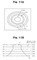
- a test piece for measuring contour lines is placed on a test bench such that the base surface 17e faces a noncontact three-dimensional laser measuring device. Measurement is executed by irradiating the base surface 17e with laser beam at an angle substantially perpendicular to the base surface 17e. The measurement results are sent to an image processing device to obtain a contour diagram of the projection 17 as shown in Fig. 11A .
- Fig. 11B shows the relationship between the base surface 17e and contour lines h (h0 to h10). As illustrated, the contour lines h are displayed at a predetermined interval from the base surface 17e along the height of the projection 17 (direction of arrow Y). Hereinafter, the distance along arrow Y with reference to the base surface 17e will be referred to as measurement height.
- FIGs. 11A and 11B show a diagram in which the contour lines h are shown at a 0.2 mm interval, the distance between the contour lines h may be changed as necessary.
- Fig. 12A is a contour diagram in which contour lines h less than 0.4 mm of measurement height are not displayed (first contour diagram).
- the area of the contour diagram as shown (W1 ⁇ W2) is a unit area for measuring the first area ratio S1.
- the area of a region R4 surrounded by the contour line h4 corresponds to the cross-sectional area of a projection that lies in the plane of a measurement height of 0.4 mm (the first cross-sectional area of the projection 17).
- the number of the regions R4 in the first contour diagram corresponds to the number of the projections 17 in the first contour diagram.
- the first area ratio S1 is calculated as the ratio of the total area of the regions R4 (SR4 ⁇ N4) to the area of the contour diagram (W1 ⁇ W2). That is, the first area ratio S1 corresponds to the total area of the first cross-sectional area in the unit area in the plane of the measurement height of 0.4 mm. In a contour diagram of the projections, that is, in a contour diagram of the outer circumferential surface of the cylinder liner body, the first area ratio S1 is equal to the ratio of the total area of the first cross-sectional areas to the area of the entire contour diagram.
- the first area ratio S1 is computed by the following equation.
- S ⁇ 1 SR ⁇ 4 ⁇ N ⁇ 4 / W ⁇ 1 ⁇ W ⁇ 2 ⁇ 100 %
- Fig. 12B is a contour diagram in which contour lines h less than 0.2 mm of measurement height are not displayed (second contour diagram).
- the area of the contour diagram (W1 ⁇ W2) is a unit area for measuring the second area ratio S2.
- the area of a region R2 surrounded by the contour line h2 corresponds to the cross-sectional area of a projection that lies in the plane of a measurement height of 0.2 mm (the second cross-sectional area of the projection 17).
- the number of the regions R2 in the second contour diagram corresponds to the number of the projections 17 in the second contour diagram. Since the area of the second contour diagram is equal to the area of the first contour diagram, the number of the projections 17 is equal to the number of projections N1.
- the second area ratio S2 is calculated as the ratio of the total area of the regions R2 (SR2 ⁇ N2) to the area of the contour diagram (W1 ⁇ W2). That is, the second area ratio S2 corresponds to the total area of the second cross-sectional area in the unit area in the plane of the measurement height of 0.2 mm. In a contour diagram of the projections, that is, in a contour diagram of the outer circumferential surface of the cylinder liner body, the second area ratio S2 is equal to the ratio of the total area of the second cross-sectional areas to the area of the entire contour diagram.
- the second area ratio S2 is computed by the following equation.
- S ⁇ 2 SR ⁇ 2 ⁇ N ⁇ 2 / W ⁇ 1 ⁇ W ⁇ 2 ⁇ 100 %
- the first cross-sectional area of the projection 17 is calculated as a cross-sectional area of one projection that lies in a plane of the measurement height of 0.4 mm based on the contour diagrams.
- the second cross-sectional area of the projection 17 is calculated as a cross-sectional area of one projection that lies in a plane of the measurement height of 0.2 mm based on the contour diagrams.
- the first cross-sectional area of the projections 17 is obtained by calculating the area of the region R4 in the first contour diagram [ Fig. 12A ].
- the second cross-sectional area of the projections 17 is obtained by calculating the area of the region R2 in the second contour diagram [ Fig. 12B ].
- the number of projections N1 is calculated as the number of the projections 17 formed per unit area (1 cm 2 ) on the outer circumferential surface 16 of the cylinder liner based on the contour diagrams. For example, through image processing of the contour diagrams, the number of projections N1 is obtained by calculating the number of the regions R4 in the first contour diagram [ Fig. 12A ].
- a cylinder liner of which the first area ratio S1 was no less than 10% and a cylinder liner of which the first area ratio S1 was less than 10% were applied to cylinder blocks, and deformation amount of these cylinder bore were compared. The deformation amount of the latter was confirmed to be more than three times that of the former.
- the voidage refers to a ratio of the area of voidage formed in the boundary between the cylinder liner and the cylinder block to the boundary cross-section.
- the second area ratio S2 is set to no more than 55%.
- the first area ratio S1 is set no less than 10%.
- each projection 17 is set to 0.2 mm 2 to 3.0 mm 2 , breakage and reduction in bond strength of the projections 17 are suppressed during the production process.
Claims (16)
- Komponente zum Insert-Gießen mit einer äußeren Umfangsoberfläche, die durch einen Insert-Gießvorgang in ein Gussmetall eingehüllt wird, wobei die Komponente zum Insert-Gießen eine Zylinderlaufbuchse ist, wobei eine Metallbeschichtungsschicht auf der äußeren Umfangsoberfläche durch ein Kaltsprühverfahren gebildet wird, dadurch gekennzeichnet, dass die äußere Umfangsoberfläche der Zylinderlaufbuchse eine Mehrzahl von Vorsprüngen aufweist, die jeweils eine verengte Form aufweisen und durch die Metallbeschichtungsschicht bedeckt sind,
wobei die Vorsprünge so ausgebildet sind, dass sie zumindest eine der nachstehenden Bedingungen (a) und (b) erfüllen:(a) Die Höhe der Vorsprünge beträgt 0,5 bis 1,5 mm; und(b) die Anzahl der Vorsprünge beträgt fünf bis sechzig pro cm2 der äußeren Umfangsoberfläche beträgt. - Komponente zum Insert-Gießen nach Anspruch 1, wobei die Metallbeschichtungsschicht aus einem Metallmaterial mit einer hohen thermischen Leitfähigkeit gebildet ist.
- Komponente zum Insert-Gießen nach Anspruch 2, wobei es sich bei dem Metallmaterial um ein beliebiges Material aus entweder Aluminium, einer Aluminiumlegierung, Kupfer oder einer Kupferlegierung handelt.
- Komponente zum Insert-Gießen nach Anspruch 1, wobei die Metallbeschichtungsschicht aus einem Metallmaterial mit einem Schmelzpunkt gebildet ist, der niedriger ist als der des Gussmetalls.
- Komponente zum Insert-Gießen nach Anspruch 4, wobei es sich bei dem Metallmaterial um ein beliebiges Material aus entweder Zink, einer Zinklegierung, Zinn, einer Zinnlegierung, Blei, einer Bleilegierung, Antimon oder einer Antimonlegierung handelt.
- Zylinderlaufbuchse, die mit einem Zylinderblock eines Verbrennungsmotors verbunden ist, wobei die Zylinderlaufbuchse aufweist:einen Zylinderlaufbuchsenkörper mit einer äußeren Umfangsoberfläche, der durch Insert-Gießen in ein Gussmetall zum Ausbilden des Zylinderblocks eingehüllt wird;eine Metallbeschichtungsschicht, die auf der äußeren Umfangsoberfläche durch ein Kaltsprühverfahren gebildet wird; undwobei die äußere Umfangsoberfläche der Zylinderlaufbuchse eine Mehrzahl von Vorsprüngen aufweist, die jeweils eine verengte Form aufweisen und durch die Metallbeschichtungsschicht bedeckt sind, wobei die Vorsprünge so ausgebildet sind, dass sie zumindest eine der nachstehenden Bedingungen (a) und (b) erfüllen:(a) Die Höhe der Vorsprünge beträgt 0,5 bis 1,5 mm; und(b) die Anzahl der Vorsprünge beträgt fünf bis sechzig pro cm2 der äußeren Umfangsoberfläche beträgt.
- Zylinderlaufbuchse nach Anspruch 6, wobei die Vorsprünge ausgebildet sind, um die nachstehenden Bedingungen (c) und (d) zu erfüllen:(c) In einem Konturdiagramm der äußeren Umfangsoberfläche des Zylinderlaufbuchsenkörpers, das durch eine dreidimensionale Lasermessvorrichtung erhalten wird, ist das Verhältnis der Gesamtfläche von Bereichen, die jeweils durch eine Konturlinie von einer Hohe von 0,4 mm umgeben sind, zur Fläche des gesamten Konturdiagramms größer oder gleich 10%; und(d) ist das Verhältnis der Gesamtfläche von Bereichen, die jeweils durch eine Konturlinie von einer Höhe von 0,2 mm umgeben sind, zur Fläche des gesamten Konturdiagramms kleiner oder gleich 55 %.
- Zylinderlaufbuchse nach Anspruch 6, wobei die Vorsprünge ausgebildet sind, um die nachstehenden Bedingungen (c') und (d') zu erfüllen:(c') In einem Konturdiagramm der äußeren Umfangsoberfläche des Zylinderlaufbüchsenkörpers, das durch eine dreidimensionale Lasermessvorrichtung erhalten wird, ist das Verhältnis der Gesamtfläche von Bereichen, die jeweils durch eine Konturlinie von einer Höhe von 0,4 mm umgeben sind, zur Fläche des gesamten Konturdiagramms 10 bis 50 %;(d') ist das Verhältnis der Gesamtfläche von Bereichen, die jeweils durch eine Konturlinie von einer Höhe von 0,2 mm umgeben sind, zur Fläche des gesamten Konturdiagramms 20 bis 55 %.
- Zylinderlaufbuchse nach Anspruch 6, wobei die Vorsprünge so ausgebildet sind, dass sie die nachstehenden Bedingungen (e) und (f) erfüllen:(e) In einem Konturdiagramm der äußeren Umfangsoberfläche der Zylinderlaufbuchse, das durch eine dreidimensionale Lasermessvorrichtung erhalten wird, sind Bereiche, die jeweils durch eine Konturlinie von einer Höhe von 0,4 mm umgeben sind, voneinander unabhängig; und(f) beträgt die Gesamtfläche von Bereichen, die jeweils durch eine Konturlinie von einer Höhe von 0,4 mm umgeben sind, 0,2 mm2 bis 3,0 mm2.
- Zylinderblock für einen Verbrennungsmotor, wobei der Zylinderblock durch Vergießen eines Metalls gebildet wird, wobei eine Zylinderlaufbuchse durch Insert-Gießen in das Metall eingehüllt wird, so dass die Zylinderlaufbuchse mit dem Zylinderblock verbunden ist, und eine äußere Umfangsoberfläche der Zylinderlaufbuchse, die mit dem Zylinderblock verbunden ist, eine Metallbeschichtungsschicht aufweist, die durch ein Kaltsprühverfahren gebildet wird; und
wobei die äußere Umfangsoberfläche der Zylinderlaufbuchse eine Mehrzahl von Vorsprüngen aufweist, die jeweils eine verengte Form aufweisen und die durch die Metallbeschichtungsschicht bedeckt sind, wobei die Vorsprünge so ausgebildet sind, dass sie zumindest eine der nachstehenden Bedingungen (a) und (b) erfüllen:(a) Die Höhe der Vorsprünge beträgt 0,5 mm bis 1,5 mm; und(b) die Anzahl der Vorsprünge beträgt fünf bis sechzig pro cm2 der äußeren Umfangsoberfläche. - Zylinderblock nach Anspruch 10, wobei es sich bei dem Metall um Aluminium oder eine Aluminiumlegierung handelt.
- Verfahren zur Herstellung einer Zylinderlaufbuchse, d. h. durch Insert-Gießen, die in ein Blockmaterial eingehüllt ist, das einen Zylinderblock eines Verbrennungsmotors ausbildet, wobei das Verfahren aufweist:Erstellen eines Zylinderlaufbuchsenkörpers;wobei die äußere Umfangsoberfläche der Zylinderlaufbuchse eine Mehrzahl von Vorsprüngen aufweist, die jeweils eine verengte Form aufweisen und die durch die Metallbeschichtungsschicht bedeckt sind, wobei die Vorsprünge ausgebildet sind, um zumindest eine der nachstehenden Bedingungen (a) und (b) zu erfüllen:(a) Die Höhe der Vorsprünge beträgt 0,5 bis 1,5 mm;(b) die Anzahl der Vorsprünge beträgt fünf bis sechzig pro cm2 auf der äußeren Umfangsoberfläche; undAusbilden einer Metallbeschichtungsschicht auf einer äußeren Umfangsoberfläche der Zylinderlaufbuchse durch ein Kaltsprühverfahren.
- Herstellungsverfahren nach Anspruch 12, wobei das Bilden der Metallbeschichtungsschicht ein Bilden, auf der äußeren Umfangsoberfläche des Zylinderlaufbuchsenkörpers, einer Metallbeschichtungsschicht beinhaltet, die aus einem Metallmaterial mit einer hohen thermischen Leitfähigkeit besteht.
- Herstellungsverfahren nach Anspruch 13, wobei das Bilden der Metallbeschichtungsschicht ein Bilden, auf der äußeren Umfangsoberfläche des Zylinderlaufbuchsenkörpers, einer Metallbeschichtungsschicht beinhaltet, die aus einem Metallmaterial besteht, bei dem es sich um ein beliebiges Material aus Aluminium, einer Aluminiumlegierung, Kupfer oder einer Kupferlegierung handelt.
- Herstellungsverfahren nach Anspruch 12, wobei das Bilden der Metallbeschichtungsschicht ein Bilden, auf der äußeren Umfangsoberfläche des Zylinderlaufbuchsenkörpers, einer Metallbeschichtungsschicht beinhaltet, die aus einem Metallmaterial mit einem Schmelzpunkt besteht, der niedriger als der des Blockmaterials ist.
- Herstellungsverfahren nach Anspruch 15, wobei das Bilden der Metallbeschichtungsschicht ein Bilden, auf der äußeren Umfangsoberfläche des Zylinderlaufbuchsenkörpers, einer Metallbeschichtungsschicht beinhaltet, die aus einem Metallmaterial besteht, bei dem es sich um ein beliebiges Material aus Zink, einer Zinklegierung, Zinn, einer Zinnlegierung, Blei, einer Bleilegierung, Antimon oder einer Antimonlegierung handelt.
Applications Claiming Priority (2)
| Application Number | Priority Date | Filing Date | Title |
|---|---|---|---|
| JP2005201004A JP4491385B2 (ja) | 2005-07-08 | 2005-07-08 | 鋳ぐるみ用部品、シリンダブロック及びシリンダライナ製造方法 |
| PCT/JP2006/313913 WO2007007814A1 (en) | 2005-07-08 | 2006-07-06 | Component for insert casting, cylinder block, and method for manufacturing cylinder liner |
Publications (2)
| Publication Number | Publication Date |
|---|---|
| EP1904666A1 EP1904666A1 (de) | 2008-04-02 |
| EP1904666B1 true EP1904666B1 (de) | 2008-12-10 |
Family
ID=37076026
Family Applications (1)
| Application Number | Title | Priority Date | Filing Date |
|---|---|---|---|
| EP06781033A Active EP1904666B1 (de) | 2005-07-08 | 2006-07-06 | Bauteil für das einsatzgiessen, zylinderblock und verfahren zur herstellung von zylinderlaufbuchse |
Country Status (9)
| Country | Link |
|---|---|
| US (1) | US7757652B2 (de) |
| EP (1) | EP1904666B1 (de) |
| JP (1) | JP4491385B2 (de) |
| KR (1) | KR101051899B1 (de) |
| CN (1) | CN100552088C (de) |
| BR (1) | BRPI0612788B1 (de) |
| DE (1) | DE602006004217D1 (de) |
| RU (1) | RU2376107C2 (de) |
| WO (1) | WO2007007814A1 (de) |
Cited By (3)
| Publication number | Priority date | Publication date | Assignee | Title |
|---|---|---|---|---|
| US11662300B2 (en) | 2019-09-19 | 2023-05-30 | Westinghouse Electric Company Llc | Apparatus for performing in-situ adhesion test of cold spray deposits and method of employing |
| US11898986B2 (en) | 2012-10-10 | 2024-02-13 | Westinghouse Electric Company Llc | Systems and methods for steam generator tube analysis for detection of tube degradation |
| US11935662B2 (en) | 2019-07-02 | 2024-03-19 | Westinghouse Electric Company Llc | Elongate SiC fuel elements |
Families Citing this family (34)
| Publication number | Priority date | Publication date | Assignee | Title |
|---|---|---|---|---|
| JP4429025B2 (ja) * | 2004-01-09 | 2010-03-10 | トヨタ自動車株式会社 | 鋳包み用シリンダライナ |
| JP2006155694A (ja) * | 2004-11-25 | 2006-06-15 | Sony Corp | ディスク信号評価装置およびディスク信号評価方法 |
| JP2007016733A (ja) * | 2005-07-08 | 2007-01-25 | Toyota Motor Corp | シリンダライナ及びエンジン |
| JP4512001B2 (ja) * | 2005-07-08 | 2010-07-28 | トヨタ自動車株式会社 | シリンダライナ、シリンダブロック及びシリンダライナ製造方法 |
| JP5388475B2 (ja) * | 2008-04-30 | 2014-01-15 | Tpr株式会社 | 鋳包構造体 |
| JP5107837B2 (ja) * | 2008-09-05 | 2012-12-26 | 富士重工業株式会社 | シリンダライナ、シリンダブロック及びシリンダライナの製造方法 |
| JP2011202576A (ja) * | 2010-03-25 | 2011-10-13 | Teikoku Piston Ring Co Ltd | シリンダライナ |
| JP2012067740A (ja) * | 2010-08-25 | 2012-04-05 | Tpr Co Ltd | 鋳包用シリンダライナ |
| FR2968358B1 (fr) * | 2010-12-02 | 2015-08-28 | Peugeot Citroen Automobiles Sa | Chemise pour bloc moteur |
| DE102010055724A1 (de) * | 2010-12-22 | 2012-06-28 | Neue Halberg-Guss Gmbh | Gussteil, insbesondere Zylinderkurbelgehäuse oder Zylinderkopf mit Kühleinrichtungen für die Abfuhr der Verbrennungswärme |
| CN103109116B (zh) * | 2011-01-12 | 2016-06-08 | 福特全球技术公司 | 用于糙化和涂敷表面的方法及一种机动车辆工件 |
| US20130032120A1 (en) * | 2011-08-04 | 2013-02-07 | Caterpillar, Inc. | Piston For Internal Combustion Engine And Method |
| US8968855B2 (en) * | 2011-10-25 | 2015-03-03 | GM Global Technology Operations LLC | Method of forming a component having an insert |
| FR2990727B1 (fr) * | 2012-05-21 | 2014-05-16 | Peugeot Citroen Automobiles Sa | Chemise de cylindre et bloc cylindres associe |
| DE102012011992A1 (de) * | 2012-06-16 | 2013-12-19 | Volkswagen Aktiengesellschaft | Metallisches Gussbauteil und Verfahren zur Herstellung eines metallischen Gussbauteils |
| BR102012025551A2 (pt) | 2012-10-05 | 2014-10-14 | Mahle Metal Leve Sa | Camisa de cilindro para engastamento em um bloco de motor e bloco de motor |
| BR102013005326A2 (pt) | 2013-03-05 | 2014-12-02 | Mahle Metal Leve Sa | Camisa de cilindro para engastamento em um bloco de motor e bloco de motor |
| WO2015009777A1 (en) | 2013-07-16 | 2015-01-22 | Federal-Mogul Corporation | Cylinder liner with bonding layer |
| US10094325B2 (en) * | 2014-01-28 | 2018-10-09 | ZYNP International Corp. | Cylinder liner |
| US20170274449A1 (en) * | 2014-11-24 | 2017-09-28 | Sikorsky Aircraft Corporation | Cast component and methods of manufacturing with cold spraying |
| US20160252042A1 (en) * | 2015-02-27 | 2016-09-01 | Avl Powertrain Engineering, Inc. | Cylinder Liner |
| KR101702222B1 (ko) | 2015-06-22 | 2017-02-03 | 주식회사 금아하이드파워 | 전차용 실린더 블록의 제조방법 |
| KR20170127903A (ko) * | 2016-05-13 | 2017-11-22 | 현대자동차주식회사 | 인서트 주조용 실린더 라이너 및 그 제조 방법 |
| CN106150740A (zh) * | 2016-06-30 | 2016-11-23 | 中原内配集团安徽有限责任公司 | 一种复合缸套及其生产方法 |
| CN109642306A (zh) * | 2016-07-13 | 2019-04-16 | 欧瑞康美科股份公司,沃伦 | 在没有预先活化表面的情况下涂覆气缸穿孔 |
| JP6572851B2 (ja) * | 2016-08-29 | 2019-09-11 | トヨタ自動車株式会社 | 内燃機関のシリンダブロックおよびその製造方法 |
| CN106438078A (zh) * | 2016-08-30 | 2017-02-22 | 中原内配集团安徽有限责任公司 | 一种铝包容气缸套的生产方法 |
| CN108085674B (zh) * | 2016-11-23 | 2020-01-03 | 中国科学院金属研究所 | 一种发动机汽缸用铝合金材料的制备方法 |
| US10253721B2 (en) * | 2017-04-12 | 2019-04-09 | GM Global Technology Operations LLC | Cylinder liner for internal combustion engine |
| KR102037582B1 (ko) * | 2017-12-18 | 2019-10-28 | 임락복 | 인서트 주조로 철계 금속 주물에 철계 금속판을 매개한 동계합금 판재 접합법. |
| KR20210037051A (ko) | 2019-09-26 | 2021-04-06 | 현대자동차주식회사 | 실린더라이너 및 그 실린더라이너가 결합된 실린더블록 |
| CN111550323A (zh) * | 2020-05-14 | 2020-08-18 | 扬州大学 | 一种具有涂层的耐穴蚀气缸套及其制备方法 |
| JP6780156B1 (ja) * | 2020-06-24 | 2020-11-04 | Tpr株式会社 | 鋳包み用シリンダライナ |
| CN113210586B (zh) * | 2021-04-29 | 2022-12-06 | 共享装备股份有限公司 | 一种汽轮机低压内缸的铸造方法 |
Family Cites Families (24)
| Publication number | Priority date | Publication date | Assignee | Title |
|---|---|---|---|---|
| JPS53163405U (de) | 1977-05-30 | 1978-12-21 | ||
| JPS61169153A (ja) * | 1985-01-23 | 1986-07-30 | Sumitomo Metal Ind Ltd | 金属−セラミツクス複合材およびその製造方法 |
| JPH01287236A (ja) * | 1988-05-13 | 1989-11-17 | Toyota Motor Corp | 金属部材の鋳ぐるみ方法 |
| JP2832032B2 (ja) * | 1989-04-28 | 1998-12-02 | 日本ピストンリング株式会社 | 鋳包み用中空筒体の製造方法 |
| DE59604435D1 (de) * | 1995-10-31 | 2000-03-16 | Volkswagen Ag | Verfahren zum herstellen einer gleitfläche auf einer leichtmetallegierung |
| DE19605946C1 (de) * | 1996-02-17 | 1997-07-24 | Ae Goetze Gmbh | Zylinderlaufbuchse für Verbrennungskraftmaschinen und ihr Herstellungsverfahren |
| DE19729017C2 (de) * | 1997-07-08 | 2001-10-31 | Federal Mogul Burscheid Gmbh | Zylinderlaufbuchse |
| DE19937934A1 (de) * | 1999-08-11 | 2001-02-15 | Bayerische Motoren Werke Ag | Zylinderkurbelgehäuse, Verfahren zur Herstellung der Zylinderlaufbuchsen dafür und Verfahren zur Herstellung des Zylinderkurbelgehäuses mit diesen Zylinderlaufbuchsen |
| DE10002440A1 (de) * | 2000-01-21 | 2001-08-02 | Daimler Chrysler Ag | Zylinderlaufbuchse zum Eingießen in einen als Leichtmetall-Gußteil ausgebildeten Motorblock, Verbundgußteil daraus und Verfahren zu seiner Herstellung |
| IT1319899B1 (it) * | 2000-02-10 | 2003-11-12 | Fiat Ricerche | Procedimento per la produzione di un blocco cilindri per un motore acombustione interna. |
| DE10019793C1 (de) * | 2000-04-20 | 2001-08-30 | Federal Mogul Friedberg Gmbh | Zylinderlaufbuchse für Verbrennungskraftmaschinen und Herstellungsverfahren |
| JP2003053508A (ja) | 2001-08-14 | 2003-02-26 | Nissan Motor Co Ltd | 熱伝導円筒部材およびその製造方法ならびに熱伝導円筒部材を用いたアルミニウム合金製エンジン |
| DE10147219B4 (de) | 2001-09-24 | 2004-02-26 | Daimlerchrysler Ag | Zylinderlaufbuchse einer Brennkraftmaschine |
| JP4210468B2 (ja) * | 2002-05-13 | 2009-01-21 | 本田技研工業株式会社 | 鋳鉄製鋳ぐるみ部材 |
| JP4210469B2 (ja) * | 2002-05-13 | 2009-01-21 | 本田技研工業株式会社 | 鋳鉄製鋳ぐるみ部材の製造方法 |
| DE60305691T2 (de) * | 2002-05-13 | 2007-05-31 | Honda Giken Kogyo K.K. | Gusseisernes inneres Glied und Herstrellungsverfahren dafür |
| DE10347510B3 (de) * | 2003-10-13 | 2005-04-28 | Federal Mogul Burscheid Gmbh | Zylinderlaufbuchse mit einer zwei Schichten umfassenden Außenbeschichtung und Verfahren zu deren Ein- oder Umgießen zu einem Verbundkörper |
| JP4429025B2 (ja) * | 2004-01-09 | 2010-03-10 | トヨタ自動車株式会社 | 鋳包み用シリンダライナ |
| JP4512002B2 (ja) * | 2005-07-08 | 2010-07-28 | トヨタ自動車株式会社 | シリンダライナ |
| JP4512001B2 (ja) * | 2005-07-08 | 2010-07-28 | トヨタ自動車株式会社 | シリンダライナ、シリンダブロック及びシリンダライナ製造方法 |
| JP4452661B2 (ja) * | 2005-07-08 | 2010-04-21 | トヨタ自動車株式会社 | 鋳ぐるみ用部品、シリンダブロック、鋳ぐるみ用部品被膜形成方法及びシリンダブロック製造方法 |
| JP4474338B2 (ja) * | 2005-07-08 | 2010-06-02 | トヨタ自動車株式会社 | シリンダライナ及びエンジン |
| JP4584058B2 (ja) * | 2005-07-08 | 2010-11-17 | トヨタ自動車株式会社 | シリンダライナ及びその製造方法 |
| JP2007016733A (ja) * | 2005-07-08 | 2007-01-25 | Toyota Motor Corp | シリンダライナ及びエンジン |
-
2005
- 2005-07-08 JP JP2005201004A patent/JP4491385B2/ja active Active
-
2006
- 2006-07-06 WO PCT/JP2006/313913 patent/WO2007007814A1/en active Application Filing
- 2006-07-06 EP EP06781033A patent/EP1904666B1/de active Active
- 2006-07-06 CN CNB2006800250072A patent/CN100552088C/zh active Active
- 2006-07-06 DE DE602006004217T patent/DE602006004217D1/de active Active
- 2006-07-06 US US11/481,084 patent/US7757652B2/en active Active
- 2006-07-06 BR BRPI0612788-6A patent/BRPI0612788B1/pt active IP Right Grant
- 2006-07-06 KR KR1020087003180A patent/KR101051899B1/ko active IP Right Grant
- 2006-07-06 RU RU2008104701/02A patent/RU2376107C2/ru active
Cited By (3)
| Publication number | Priority date | Publication date | Assignee | Title |
|---|---|---|---|---|
| US11898986B2 (en) | 2012-10-10 | 2024-02-13 | Westinghouse Electric Company Llc | Systems and methods for steam generator tube analysis for detection of tube degradation |
| US11935662B2 (en) | 2019-07-02 | 2024-03-19 | Westinghouse Electric Company Llc | Elongate SiC fuel elements |
| US11662300B2 (en) | 2019-09-19 | 2023-05-30 | Westinghouse Electric Company Llc | Apparatus for performing in-situ adhesion test of cold spray deposits and method of employing |
Also Published As
| Publication number | Publication date |
|---|---|
| JP4491385B2 (ja) | 2010-06-30 |
| DE602006004217D1 (de) | 2009-01-22 |
| US20070012180A1 (en) | 2007-01-18 |
| KR101051899B1 (ko) | 2011-07-28 |
| WO2007007814A1 (en) | 2007-01-18 |
| BRPI0612788A2 (pt) | 2012-01-03 |
| US7757652B2 (en) | 2010-07-20 |
| CN100552088C (zh) | 2009-10-21 |
| JP2007016738A (ja) | 2007-01-25 |
| EP1904666A1 (de) | 2008-04-02 |
| BRPI0612788B1 (pt) | 2018-03-27 |
| KR20080027928A (ko) | 2008-03-28 |
| CN101218374A (zh) | 2008-07-09 |
| RU2376107C2 (ru) | 2009-12-20 |
| RU2008104701A (ru) | 2009-08-20 |
Similar Documents
| Publication | Publication Date | Title |
|---|---|---|
| EP1904666B1 (de) | Bauteil für das einsatzgiessen, zylinderblock und verfahren zur herstellung von zylinderlaufbuchse | |
| EP1902210B1 (de) | Umspritzgiessteil, zylinderblock, verfahren zur formung einer beschichtung auf einem umspritzgiessteil sowie verfahren zur herstellung eines zylinderblocks | |
| US8037860B2 (en) | Cylinder liner and engine | |
| EP1904250B1 (de) | Zylinderlaufbuchse, zylinderblock und verfahren zur herstellung der zylinderlaufbuchse | |
| US7882818B2 (en) | Cylinder liner and engine | |
| EP1711291B1 (de) | Zylinderbuchse für Verbundguss | |
| EP2151568B1 (de) | Zylinderblock mit einer Zylinderlaufbüchse und Herstellungsverfahren dafür | |
| EP2422902B1 (de) | Zylinderlaufbuchse zum Eingießen | |
| JP2002541322A (ja) | 軽金属シリンダーブロック、その製造方法、およびその製造方法を実施するための装置 | |
| JP5388298B2 (ja) | 鋳包み用の溶射皮膜付鋳鉄部材並びにその製造方法及び鋳包み用の溶射皮膜付シリンダライナ |
Legal Events
| Date | Code | Title | Description |
|---|---|---|---|
| PUAI | Public reference made under article 153(3) epc to a published international application that has entered the european phase |
Free format text: ORIGINAL CODE: 0009012 |
|
| 17P | Request for examination filed |
Effective date: 20080109 |
|
| AK | Designated contracting states |
Kind code of ref document: A1 Designated state(s): DE FR GB IT TR |
|
| DAX | Request for extension of the european patent (deleted) | ||
| RIN1 | Information on inventor provided before grant (corrected) |
Inventor name: HORIGOME, MASAMI Inventor name: SAITO, GIICHIRO Inventor name: MIHARA, TOSHIHIRO Inventor name: SHIBATA, KOUHEI Inventor name: TAKAMI, TOSHIHIRO Inventor name: SATO, TAKASHI Inventor name: MIYAMOTO, NORITAKA Inventor name: YAMASHITA, NOBUYUKI Inventor name: HIRANO, MASAKI |
|
| GRAP | Despatch of communication of intention to grant a patent |
Free format text: ORIGINAL CODE: EPIDOSNIGR1 |
|
| DAX | Request for extension of the european patent (deleted) | ||
| RBV | Designated contracting states (corrected) |
Designated state(s): DE FR GB IT TR |
|
| GRAS | Grant fee paid |
Free format text: ORIGINAL CODE: EPIDOSNIGR3 |
|
| GRAA | (expected) grant |
Free format text: ORIGINAL CODE: 0009210 |
|
| AK | Designated contracting states |
Kind code of ref document: B1 Designated state(s): DE FR GB IT TR |
|
| REG | Reference to a national code |
Ref country code: GB Ref legal event code: FG4D |
|
| REF | Corresponds to: |
Ref document number: 602006004217 Country of ref document: DE Date of ref document: 20090122 Kind code of ref document: P |
|
| PLBE | No opposition filed within time limit |
Free format text: ORIGINAL CODE: 0009261 |
|
| STAA | Information on the status of an ep patent application or granted ep patent |
Free format text: STATUS: NO OPPOSITION FILED WITHIN TIME LIMIT |
|
| 26N | No opposition filed |
Effective date: 20090911 |
|
| REG | Reference to a national code |
Ref country code: GB Ref legal event code: 746 Effective date: 20130412 |
|
| REG | Reference to a national code |
Ref country code: DE Ref legal event code: R084 Ref document number: 602006004217 Country of ref document: DE Effective date: 20130410 |
|
| REG | Reference to a national code |
Ref country code: FR Ref legal event code: PLFP Year of fee payment: 11 |
|
| REG | Reference to a national code |
Ref country code: FR Ref legal event code: PLFP Year of fee payment: 12 |
|
| REG | Reference to a national code |
Ref country code: FR Ref legal event code: PLFP Year of fee payment: 13 |
|
| P01 | Opt-out of the competence of the unified patent court (upc) registered |
Effective date: 20230427 |
|
| PGFP | Annual fee paid to national office [announced via postgrant information from national office to epo] |
Ref country code: IT Payment date: 20230612 Year of fee payment: 18 Ref country code: FR Payment date: 20230510 Year of fee payment: 18 |
|
| PGFP | Annual fee paid to national office [announced via postgrant information from national office to epo] |
Ref country code: TR Payment date: 20230705 Year of fee payment: 18 Ref country code: GB Payment date: 20230518 Year of fee payment: 18 |
|
| PGFP | Annual fee paid to national office [announced via postgrant information from national office to epo] |
Ref country code: DE Payment date: 20230510 Year of fee payment: 18 |