EP1904158B1 - Faltbares Pflaster mit Mikronadelnanordnung - Google Patents
Faltbares Pflaster mit Mikronadelnanordnung Download PDFInfo
- Publication number
- EP1904158B1 EP1904158B1 EP06785523.9A EP06785523A EP1904158B1 EP 1904158 B1 EP1904158 B1 EP 1904158B1 EP 06785523 A EP06785523 A EP 06785523A EP 1904158 B1 EP1904158 B1 EP 1904158B1
- Authority
- EP
- European Patent Office
- Prior art keywords
- patch
- microneedle
- base
- microneedle array
- carrier
- Prior art date
- Legal status (The legal status is an assumption and is not a legal conclusion. Google has not performed a legal analysis and makes no representation as to the accuracy of the status listed.)
- Not-in-force
Links
Images


Classifications
-
- A—HUMAN NECESSITIES
- A61—MEDICAL OR VETERINARY SCIENCE; HYGIENE
- A61M—DEVICES FOR INTRODUCING MEDIA INTO, OR ONTO, THE BODY; DEVICES FOR TRANSDUCING BODY MEDIA OR FOR TAKING MEDIA FROM THE BODY; DEVICES FOR PRODUCING OR ENDING SLEEP OR STUPOR
- A61M37/00—Other apparatus for introducing media into the body; Percutany, i.e. introducing medicines into the body by diffusion through the skin
- A61M37/0015—Other apparatus for introducing media into the body; Percutany, i.e. introducing medicines into the body by diffusion through the skin by using microneedles
-
- A—HUMAN NECESSITIES
- A61—MEDICAL OR VETERINARY SCIENCE; HYGIENE
- A61K—PREPARATIONS FOR MEDICAL, DENTAL OR TOILETRY PURPOSES
- A61K9/00—Medicinal preparations characterised by special physical form
- A61K9/0012—Galenical forms characterised by the site of application
- A61K9/0019—Injectable compositions; Intramuscular, intravenous, arterial, subcutaneous administration; Compositions to be administered through the skin in an invasive manner
- A61K9/0021—Intradermal administration, e.g. through microneedle arrays, needleless injectors
-
- A—HUMAN NECESSITIES
- A61—MEDICAL OR VETERINARY SCIENCE; HYGIENE
- A61M—DEVICES FOR INTRODUCING MEDIA INTO, OR ONTO, THE BODY; DEVICES FOR TRANSDUCING BODY MEDIA OR FOR TAKING MEDIA FROM THE BODY; DEVICES FOR PRODUCING OR ENDING SLEEP OR STUPOR
- A61M37/00—Other apparatus for introducing media into the body; Percutany, i.e. introducing medicines into the body by diffusion through the skin
- A61M37/0015—Other apparatus for introducing media into the body; Percutany, i.e. introducing medicines into the body by diffusion through the skin by using microneedles
- A61M2037/0023—Drug applicators using microneedles
Definitions
- the present invention relates to microneedle patches and patch assemblies, and more particularly to collapsible microneedle patches and patch assemblies for carrying and delivering microneedle arrays.
- stratum corneum the outermost layer of the skin.
- microneedles Devices including arrays of relatively small structures, sometimes referred to as microneedles or micro-pins, have been disclosed for use in connection with the delivery of therapeutic agents, vaccines and other substances through the skin and other surfaces.
- the devices are typically pressed against the skin to deliver molecules to a particular location.
- Microneedles of these devices pierce the stratum corneum upon contact, making a plurality of microscopic slits which serve as passageways through which molecules of active components can be delivered into the body.
- the microneedle device can be provided with a reservoir for temporarily retaining an active component in liquid form prior to delivering the active component through the stratum corneum.
- the microneedles can be hollow to provide a liquid flow path directly from the reservoir and through the microneedles to enable delivery of the therapeutic substance through the skin.
- active component(s) may be coated on the microneedle array and delivered directly through the skin after the stratum corneum has been punctured.
- Microneedle arrays can be used in conjunction with an applicator device capable of being used a number of different times.
- the microneedle arrays are generally used once and then discarded.
- Microneedles can be delivered using a patch that carries the microneedles.
- the patches are typically manufactured in a flat sheet-like configuration, carrying the microneedles.
- Patches may be temporarily attached to a disposable collar for an applicator device using, for example, an adhesive.
- the disposable collar may then be temporarily attached to the applicator using, for example, a mechanical snap-fit.
- Patches with or without a microneedles, can have fragile and sanitary characteristics. It is generally desired that the patch and array not be touched before application to a target site. This presents difficulties in storing and transporting patches to desired locations for eventual application.
- the patches may be stored along with the collars. However, the collars are large, and storage of disposable collars takes up excessive space and generates excessive waste.
- a microneedle patch according to the preamble of claim 1 is known from WO 01/93931 .
- the microneedle patches describes in WO 2006/055 795 A1 from state of the art under Article 54(3) EPC.
- a microneedle patch in a first aspect of the present invention, includes a base having an upper face and a lower face, at least one side wall extending from the base, and a lip disposed outwardly along the at least one sidewall and opposite the base.
- An adhesive is disposed along the lower face of the base, and a microneedle array is affixed to the lower face of the base, wherein the thickness of the side wall is less than the thickness of the base such that the side wall is foldable upon itself.
- a microneedle patch system in another aspect useful for the present invention, includes a collapsible patch element having a base and at least one side wall extending from the base.
- the base of the collapsible patch element has an upper face and an opposite bottom face, and the at least one side wall generally extends from the bottom face of the base.
- a microneedle array is affixed to the bottom face of the base of the collapsible patch element, and a first carrier is disposed adjacent to the collapsible patch element and relative to the bottom face of the base. The first carrier covers the microneedle array, and is separable from the collapsible patch element.
- a microneedle patch assembly in another aspect useful for the present invention, includes a web of material having an upper face and a lower face, an adhesive disposed along the lower face of the web of material, and a microneedle array affixed to the lower face of the web of material.
- the patch has a first state where the web of material defines a first volume relative to its lower face and the microneedle array is spaced from a target site.
- the patch also has a second state where the web of material defines a second volume that is less than the first volume and the microneedle array contacts the target site.
- a method of microneedle array deployment includes positioning a patch carrying a microneedle array relative to a target site and collapsing at least a portion of the patch while moving the microneedle array toward the target site.
- a method of microneedle array deployment includes positioning a patch carrying a microneedle array near a target site.
- the patch is initially in an expanded state and the microneedle array is spaced from the target site.
- the microneedle array is moved toward the target site by placing the patch in a collapsed state, where at least a portion of the patch is collapsed and the microneedle array contacts the target site.
- the patch is also adhered to the target site with an adhesive disposed on the patch.
- a microneedle patch assembly in another aspect useful for the present invention, includes a patch element having, in an initial expanded state, a first skin contacting surface and a second surface spaced from the first surface. A microneedle array is affixed to the second surface of the patch element.
- a microneedle patch system in another aspect useful for the present invention, includes a plurality of collapsible patch elements nested together to form a package.
- Each collapsible patch element includes a base having an upper face and an opposite bottom face, at least one side wall extending from the base, and a microneedle array affixed to the bottom face of the base.
- the at least one side wall generally extends from the bottom face of the base.
- Patches can be used for transdermal delivery of molecules, and can carry microneedle arrays, which have utility for the delivery of large molecules that are ordinarily difficult to deliver by passive transdermal delivery.
- array refers to the medical devices described herein that include one or more structures capable of piercing the stratum corneum to facilitate the transdermal delivery of therapeutic agents or the sampling of fluids through or to the skin.
- Microstructure “microneedle” or “microarray” refers to the specific microscopic structures associated with the array that are capable of piercing the stratum corneum to facilitate the transdermal delivery of therapeutic agents or the sampling of fluids through the skin.
- microstructures can include needle or needle-like structures as well as other structures capable of piercing the stratum corneum.
- the microneedles are typically less than 500 microns in height, and sometimes less than 300 microns in height.
- the microneedles are typically more than 20 microns in height, often more than 50 microns in height, and sometimes more than 125 microns in height.
- FIGS. 1-2B and 3A-3B show a first embodiment of a collapsible microneedle patch 30 according to the present invention that has a first, expanded state and a second, collapsed state.
- FIG. 1 is a perspective view of the microneedle patch 30 in the expanded state.
- FIG. 2A is a side view of the microneedle patch 30 in the expanded state.
- FIG. 2B is a cross-sectional view of the microneedle patch 30 in the expanded state.
- the microneedle patch 30 has a collapsible patch element comprising a generally circular base portion 32, at least one side wall 34 extending from the base portion 32, and a perimeter lip 36 extending from the side wall 34 opposite the base portion 32.
- the base portion 32, the side wall 34 and the perimeter lip 36 can be formed integrally.
- An adhesive 38 is disposed on the base portion 32, and a microneedle array 40 is supported by the base portion 32 (individual microneedles of the array 40 are not visible in the figures). As seen in FIG.
- the side wall 34 is disposed at an angle between the perimeter of the base portion 32 and the inner diameter of the perimeter lip 36, such that the inner diameter of the perimeter lip 36 is larger than the perimeter (i.e., the outer diameter) of the base portion 32 (measured with respect to an axis 42 defined at a center of the patch 30).
- the side wall may be generally perpendicular to the base and the lip, such that the inner diameter of the perimeter lip 36 would be about the same size as the perimeter of the base portion 32.
- the side wall may be angled such that the inner diameter of the perimeter lip 36 would be smaller than the perimeter of the base portion 32, although the inner diameter of the perimeter lip should be large enough to allow the microneedle array 40 to contact a target surface.
- the side wall 34 also generally has a smaller thickness T SW than thicknesses T B and T L of the base portion 32 and the perimeter lip 36, respectively.
- the patch may further comprise an adhesive (not shown in FIGS. 1-2B ) disposed along the surface of the lip opposed to the base.
- the side wall thickness T SW is about 0.0001 inches (0.00254 mm) to about 0.010 inches (0.254 mm), and is preferably about 0.0005 inches (0.0127 mm) to about 0.005 inches (0.127 mm).
- the outer diameter of the perimeter lip 36 is typically about 1 inch (2.54 cm) to about 3 inches (7.62 cm)
- the outer diameter of the base portion 32 is typically about 0.5 inches (1.27 cm) to about 2.5 inches (6.35 cm).
- An overall height H E of the patch 30 (in the expanded state) is typically about 0.1 inches (0.254 cm) to about 1 inch (2.54 cm).
- the base thickness T B is about 0.005 inches (0.127 mm) to about 0.050 inches (1.27 mm).
- the lip thickness T L is about 0.005 inches (0.127 mm) to about 0.050 inches (1.27 mm).
- the base portion 32 and the perimeter lip 36 are each generally planar. When the patch 30 is in the expanded state, the base portion 32 and the perimeter lip 36 are spaced from one another (i.e., are not coplanar). The base portion 32, the perimeter lip 36 and the side wall 34 define a volume V E relative to a bottom face of the patch 30.
- the patch 30 has enough rigidity to remain in the expanded state without undesired collapse prior to application, due to external factors such as gravity and slight inadvertent contact.
- FIGS. 1-2B the microneedle array 40 is affixed to the base portion 32 by the adhesive 38. Furthermore, the adhesive 38 extends along the base portion 32 beyond the microneedle array 40 and surrounds the microneedle array 40.
- the microneedle array 40 can also be connected to the base portion 32 in other ways.
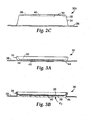
- FIG. 2C is a side view of another embodiment of a microneedle patch 30C in the expanded state. As shown in FIG. 2C , the microneedle array 40 is connected to the base portion 32, without adhesive disposed therebetween. Such a connection can be made by processes such as welding and directly forming the microneedle array 40 on the base portion 32. As shown in FIG. 2C , the adhesive 38 is disposed on the base portion 32 around the microneedle array 40.
- FIG. 3A is a side view of the microneedle patch 30 in the collapsed state.
- FIG. 3B is a cross-sectional view of the microneedle patch 30 in the collapsed state.
- the base portion 32 and the perimeter lip 36 are closer together than in the expanded state.
- the microneedle array 40 extends at least as far, and preferably beyond, a skin-contacting face 44 of the perimeter lip 36 of the patch 30.
- the base portion 32, the perimeter lip 36 and the side wall 34 define a volume V C , which is less than a volume V E defined in the expanded state.
- Collapsing of the patch 30 involves deformation of a portion of the patch 30, for example, deforming the side wall 34.
- the relatively thin wall thickness T SW of the side wall 34 facilitates collapse of the patch 30, and allows increased predictability in the deformation pattern (i.e., the characterization of deformation of the patch 30 resulting from collapse) for increasing reliability of microneedle array 40 deployment.
- This deformation may take many forms, and FIGS. 3A and 3B are merely exemplary of this result. It should be recognized that other deformation patterns are possible.
- At least the circular base portion 32, the side wall 34, and the perimeter lip 36 of the patch 30 are preferably formed of a thermoplastic material, such as polypropylene, polybutylene terephthalate, polystyrene, polyethylene, polythermide, polyethylene terephthalate, polystyrene, polyvinyl chloride, polymethylmethacrylate, acrylonitrile-butadiene styrene, polycarbonate, and blends thereof.
- Other possible materials include metal foils, such as aluminum, steel, and stainless steel.
- the base 32, side wall 34, and perimeter lip 36 may be made of a single material or they may be formed using separate materials.
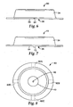
- FIG. 4 is a perspective view of another embodiment of a microneedle patch 50 having a plurality of slots 52A-52D defined therethrough to form venting features.
- the microneedle patch 50 is generally similar to those shown and described with respect to FIGS. 1-3B .
- the slots 52A-52D are each generally elongated in shape, and extend from the base portion 32, along the side wall 34 and into the perimeter lip 36.
- FIG. 5 is a top view of the microneedle patch 50.
- the slots 52A-52D may be spaced equally about axis 42. As shown in FIGS. 4 and 5 , there are four slots 52A-52D and they are positioned 90° from each other with respect to axis 42.
- the slots 52A-52D extend through the patch 50 to create openings or passageways, which permit air to pass through the side wall 34. Openings defined by the slots 52A-52D allow air to escape from the interior volume of the patch 50 as it collapses. This helps promote predictable movement of the microneedle array 40 during deployment, and helps reduce sound (e.g., a "popping" sound) generated during patch collapse.
- the sizes of each of the slots 52A-52D can be selected according to the amount of airflow desired during collapse of the patch 50.
- the slots 52A-52D can be pre-formed in the patch 50, or formed or cut into the patch 50 as part of a patch application process.
- a vented system will have at least one air outlet defined in the collapsible patch element, so that it allows venting when the patch is placed against a continuous target surface and the patch volume is compressed.
- FIG. 6 is a side view of a portion of another embodiment of a microneedle patch 60 having a channel 62 defined therethrough.
- the channel 62 is substantially an inverted U-shape and disposed in a perimeter lip 36, along a bottom, skin contacting face 64 of the perimeter lip 36.
- the channel 62 creates a generally radially extending opening or passageway that permits air to escape from the interior volume of the patch 60 as it collapses.
- the size of the channel can be selected according to the amount of airflow desired during collapse of the patch 60.
- One or more channels can be included, as desired.
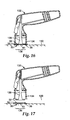
- FIG. 7 is a side view of a portion of another embodiment of a microneedle patch 70 having a rib 72 disposed thereon.
- the rib 72 can be a protrusion extending from a bottom, skin-contacting face 64 of a perimeter lip 36 of the patch 70.
- the rib 72 is elongate, and extends generally radially along the perimeter lip 36.
- the rib 72 can have nearly any shape, and nearly any number of ribs can be included.
- the skin-contacting face 64 of the perimeter lip 36 is positioned against a surface (e.g., against the skin of a patient or test subject), the rib 72 spaces at least a portion of the surface from the skin-contacting face 64 of the perimeter lip 36. This creates a passageway adjacent the rib 72 that permits air to escape from the interior volume of the patch 70 as it collapses.
- the height of the rib 72 can be selected according to the amount of airflow desired during collapse of the patch 70.
- FIG. 8 is a bottom view of a microneedle patch 80 showing possible feature locations 82A-82D.
- Airflow features such as those shown and described with respect to FIGS. 6 and 7 can be disposed at any or all of the locations 82A-82D.
- the airflow features (at locations 82A-82D) can extend generally radially along the perimeter lip 36, relative to axis 42.
- Other feature locations are possible, as those shown in FIG. 8 are merely exemplary.
- FIG. 19 is a cross-sectional view of another embodiment of a microneedle patch in an expanded state.
- the microneedle patch 230 has a collapsible patch element comprising a generally circular base portion 232, at least one side wall 234 extending from the base portion 232, and a perimeter lip 236 extending from the side wall 234 opposite the base portion 232.
- the base portion 232, the side wall 234 and the perimeter lip 236 can be formed integrally.
- An adhesive 238 is disposed on the base portion 232, and a microneedle array 240 is supported by the base portion 232 (individual microneedles of the array 240 are not visible in the figures).
- the side wall 234 is generally perpendicular to the base 232 and the lip 236, such that the inner diameter of the perimeter lip 236 is about the same size as the perimeter of the base portion 232. As seen in FIG. 19 , the side wall 234 is pleated, such that it can fold in a manner similar to an accordion.
- FIG. 20 is a cross-sectional view of the microneedle patch 230 in the collapsed state where the pleats have been pressed against one another.
- packages according to the present invention can be provided. These packages offer protection to microneedle arrays that are often fragile and contamination-sensitive. In addition, these packages permit storage of the collapsible microneedle patches while reducing the risk of undesired patch collapse, due to inadvertent contact or other factors.
- FIG. 9 is a cross-sectional view of a microneedle patch assembly 90 that includes a microneedle patch 30 and a carrier 92 that together form a closed package.
- the carrier 92 includes a base portion 94, a raised portion 96, and a recess 98 disposed in the raised portion 96.
- the patch 30 is positioned on the carrier 92, such that the raised portion 96 of the carrier 92 extends at least partially into the volume defined between the base 32 and the side wall 34 of the patch 30.
- the recess 98 extends toward the base portion 94 of the carrier 92, creating a volume into which the microneedle array 40 can extend.
- the carrier can be shaped in other ways. For instance, the raised portion 96 need not come into contact with the base 32 (or adhesive 38 disposed on the base 32) of the patch 30.
- a number of discrete raised portions 96 can extend from a single base portion 94 of the carrier 92. This permits a plurality of individual patches 30 to be carried on a single carrier 92.
- the carrier 92 can be optionally adhered to the patch 30, for example, by the adhesive 38.
- the carrier 92 can be adhered to the patch 30 with adhesive disposed on the perimeter lip 36.
- the portion 94 of the carrier 92 that contacts the perimeter lip 36 of the patch 30 may be a release or non-stick surface, such that the adhesive of the patch may be easily removed from it. This may be achieved by suitable selection of adhesive and carrier material or it may be desirable to provide a release coating, such as a low surface energy silicone, fluoropolymer, or fluoro-silicone release coating on the carrier 92.
- the carrier 92 is separable from the patch 30.
- the patch 30 can be positioned on the carrier 92 for storage and transportation.
- the carrier 92 is then removed from the patch 30 prior to application of the patch 30 to a patient. Because the carrier 92 is only disposed relative to one side of the patch 30, an operator can pick up the patch 30 and separate it from the carrier 92 either manually or with a tool such as a patch applicator device.
- the carrier 92 is typically formed so as to be relatively rigid.
- Suitable materials include polymers, such as polypropylene, polybutylene terephthalate, polystyrene, polyethylene, polythermide, polyethylene terephthalate, polystyrene, polyvinyl chloride, polymethylmethacrylate, acrylonitrile-butadiene styrene, polycarbonate, and blends thereof.
- the carrier may be formed from the same material as the collapsible patch element, but the carrier thickness will typically be greater than the thickness of part or all of the patch element. Rigidity of the carrier 92 offers protection to the patch 30 from undesired collapse, and from damage and contamination.
- FIG. 10 is a cross-sectional view of another embodiment of a microneedle patch assembly 100.
- the assembly 100 includes a patch 30, a (first) carrier 92, and a second carrier 102 that together form a package.
- the patch 30 and the carrier 92 are similar to those shown and described with respect to FIG. 9 .
- the second carrier 102 includes a base portion 104 and a raised portion 106 extending from the base portion 104.
- the patch 30 is disposed on the (first) carrier 92, and the second carrier 102 is disposed on or over the patch 30, opposite the (first) carrier 92.
- the raised portion 106 of the second carrier 102 defines a volume into which the patch 30 can extend.
- the raised portion 96 of the (first) carrier 92 can also extend into the volume defined by the raised portion 106 of the second carrier 102.
- the (first) carrier 92 and the second carrier 102 can be sealed or adhered together about their respective peripheries (such as at location 105 in FIG. 10 ) in order to better protect the patch 30 for contamination and other damage, as well as to better preserve any substances (e.g., pharmaceuticals) carried by the microneedle array 40. Sealing may be by any suitable means, such as by use of an adhesive or a heat seal. In one embodiment a hermetic seal is provided to protect the patch from environmental influences so that the patch may be stored, for example, while maintaining sterility.
- Both carriers may be separable from the patch and one or both may be removed by hand or with the aid of an applicator device. They may be removed in any order or they may be removed simultaneously.
- the second carrier is generally formed so as to be relatively rigid and in one embodiment may be formed from the same material as the first carrier.
- FIG. 11 is a cross-sectional view of another embodiment of a microneedle patch assembly 110.
- the assembly 110 is similar to that shown and described with respect to FIG. 10 .
- an opening 112 is defined through a center region of the raised portion 106 of the second carrier 102.
- the opening 112 permits access to the patch 30 near the microneedle array 40.
- the opening 112 can allow a portion of a patch applicator device to contact the base 32 of the patch 30 above the microneedle array 40 to apply a force, which can collapse the patch 30 and move the microneedle array 40 toward a target site (after the (first) carrier 92 is removed).
- the opening 112 Prior to deployment of the microneedle array 40, for storage and transportation, the opening 112 can be covered and sealed, for instance, with foil or other type of removable cover.
- the second carrier may be removed after collapse of the patch while allowing the patch to remain in contact with the target surface. Alternatively, the second carrier may stay in place on the target surface until removal of the patch.
- FIG. 12 is a cross-sectional view of a stack 120 of a plurality of nested microneedle patch assemblies 100 that forms a package.
- the raised portion 106 of the second carrier 102 of one patch assembly 100A extends into the volume defined by the raised portion 96 of the (first) carrier 92 of an adjacent patch assembly 100B.
- Almost any number of patch assemblies 100 can be nested together.
- different types of patch assemblies can be stacked together.
- the stack 120 facilitates storage and transportation of patch assemblies.
- a patch 30 according to the present invention can be applied to a target location using an applicator device.
- suitable microneedle application devices are disclosed in International Patent Publication WO 05/123173 and U.S. Patent Application Publication No. 2002-0087182 .
- patch applicators can be used to apply the patch 30.
- a first method of applying a patch includes adhering the patch to a surface and then bringing an applicator device to the patch for activation.
- FIG. 13 is a cross-sectional view of a microneedle patch 30 in an expanded state adhered to an application surface 130, and a microneedle patch applicator 132 spaced from the patch 30.
- the patch 30 can be adhered to the application surface 130, for example, by adhesive disposed on the perimeter lip 36 of the patch 30.
- the microneedle patch applicator 132 can be placed over the patch 30.
- a collar portion 134 can then engage the patch 30, and, in one embodiment, may include one or more vent cutters thereon for cutting through a portion or portions of the patch 30 to form vent openings therethrough.
- the patch applicator 132 is activated, as explained below, to engage the microneedle array 40 with the application surface 130. It should be understood that after the patch is adhered to the target surface it may simply be pressed manually to engage the microneedle array with the application surface. Manual application, however, may not be as reproducible as that obtained with an appropriately configured applicator device.
- FIG. 14 is a cross-sectional view of a microneedle patch 30 in an expanded state held on a microneedle patch applicator 132.
- the patch applicator 132 has an outer collar portion 134, which can be cylindrical in shape or have another shape that corresponds to a shape of the patch 30.
- the perimeter lip 36 of the patch 30 can rest against a bottom portion of the collar 134 of the applicator device 132, and the side wall 34 and base 32 of the patch 30 can extend into an interior portion of the collar 134.
- the microneedle array 40 of the patch 30 is generally disposed in the interior portion of the collar 134 of the applicator device 132.
- FIG. 15 is a cross-sectional view of a microneedle patch 30 in an expanded state held on a microneedle patch applicator 132, with both the patch 30 and the applicator 132 positioned relative to an application surface 130 prior to microneedle array 40 deployment to a target site 136.
- a patch accelerator 138 of the applicator device 132 is spaced from the patch 30 and has not yet contacted or moved the patch 30.
- FIG. 16 is a cross-sectional view of the microneedle patch 30 in a collapsed state after deployment of the microneedle array 40 to the target site 136 on the application surface 130 by the microneedle patch applicator 132.
- the microneedle array 40 has been moved into contact with the application surface 130 by the patch accelerator 138.
- the patch 30 can be adhered to the application surface 130 with an adhesive 38 disposed on the base 32 of the patch 30, as desired.
- FIG. 17 is a cross-sectional view of the microneedle patch 30 adhered to the application surface 130 after microneedle array 40 deployment, with the microneedle patch applicator 132 spaced from the patch 30 (i.e., the collar 134 of the applicator device 132 does not contact the patch 30).
- an applicator will accelerate the microneedle array 40 to a desired velocity that is effective to pierce the microneedles into the skin.
- the desired velocity is preferably controlled to limit or prevent stimulation of the underlying nerve tissue.
- the maximum velocity achieved by the microneedle array upon impact with the skin is often 20 meters per second (m/s) or less, potentially 15 m/s or less, and possibly 10 m/s or less. In some instances, the maximum velocity may be 8 m/s or less. In other instances, the minimum velocity achieved by the microneedle array upon impact with the skin is often 2 m/s or more, potentially 4 m/s or more, and possibly 6 m/s or more.
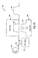
- FIG. 18 is a schematic representation of a manufacturing system 180 for producing microneedle patches according to the present invention.
- the system 180 includes a film heater 182 and a die tool 184 having at least one cavity 186. Additional cavities can be provided in the die tool 184.
- the system 180 further includes a movable plug 188 having an engagement portion 190 for cooperatively engaging the cavity 186 of the die tool 184.
- the die tool 184 can utilize a vacuum forming assembly either in addition to or in place of plug assist from the plug 188.
- a web of material 192 is provided.
- the web of material 192 can be in the form of a film from a roll 194 of film stock.
- the web of material 192 is unrolled, and is heated by the film heater 182. This heating helps prepare the web of material 192 for being formed into a three-dimensional shape by making it more readily deformable.
- a portion of the heated web of material 192 is positioned at the cavity 186 of the die tool 184, between the die tool 184 and the plug 188.
- the plug 188 moves toward the die tool 184 such that the engagement portion 190 of the plug and the cavity 186 of the die tool 184 cooperatively deform the web of material 192 to form at least one collapsible patch (e.g., collapsible patch 30 shown and described with respect to FIGS. 1-2B and 3A-3B ). Then the plug 188 is moved away from the die tool 184. A formed patch element 196 of the web of material 192, formed with the die tool 184 and plug 188, is then moved away from the die tool 184.
- collapsible patch e.g., collapsible patch 30 shown and described with respect to FIGS. 1-2B and 3A-3B
- Additional patch elements can be formed on the web of material 192 in a similar fashion as that described above.
- the individual patch elements can be separated from each other after they have been formed, or the patch elements can remain connected for transportation and further processing (e.g., for connecting microneedles arrays and or for affixing adhesive to a portion of the lower face of the web material).
- a microneedle array may be formed directly on the web of material 192 during a forming step that can take place before, after, or concurrent wit the plug forming step. Additional details regarding molding processes suitable for forming a microneedle array as part of a web may be found in United States.Patent Application Serial No. 60/753,808, filed December 23, 2005 .
- microneedle arrays useful in the various embodiments of the invention may comprise any of a variety of configurations, such as those described in the following patents and patent applications, the disclosures of which are herein incorporated by reference.
- One embodiment for the microneedle arrays comprises the structures disclosed in United States Patent Application Publication No. 2003/0045837 .
- the disclosed microstructures in the aforementioned patent application are in the form of microneedles having tapered structures that include at least one channel formed in the outside surface of each microneedle.
- the microneedles may have bases that are elongated in one direction.
- the channels in microneedles with elongated bases may extend from one of the ends of the elongated bases towards the tips of the microneedles.
- the channels formed along the sides of the microneedles may optionally be terminated short of the tips of the microneedles.
- the microneedle arrays may also include conduit structures formed on the surface of the substrate on which the microneedle array is located. The channels in the microneedles may be in fluid communication with the conduit structures.
- Another embodiment for the microneedle arrays comprises the structures disclosed in U. S. Patent Application Publication No. 2005/0261631 , which describes microneedles having a truncated tapered shape and a controlled aspect ratio.
- Still another embodiment for the microneedle arrays comprises the structures disclosed in United States Patent No. 6,091,975 (Daddona, et al. ) which describes blade-like microprotrusions for piercing the skin.
- Still another embodiment for the microneedle devices comprises the structures disclosed in United States Patent No. 6,313,612 (Sherman, et al. ) which describes tapered structures having a hollow central channel. Still another embodiment for the micro arrays comprises the structures disclosed in U. S. Patent No. 6,379,324 (Gartstein, et al. ) which describes hollow microneedles having at least one longitudinal blade at the top surface of tip of the microneedle.
- Microneedle patches of the present invention may be used to deliver drugs (including any pharmacological agent or agents) through the skin in a variation on transdermal delivery, or to the skin for intradermal or topical treatment, such as vaccination.
- drugs that are of a large molecular weight may be delivered transdermally. Increasing molecular weight of a drug typically causes a decrease in unassisted transdermal delivery.
- Microneedle patches of the present invention have utility for the delivery of large molecules that are ordinarily difficult to deliver by passive transdermal delivery. Examples of such large molecules include proteins, peptides, nucleotide sequences, monoclonal antibodies, DNA vaccines, polysaccharides, such as heparin, and antibiotics, such as ceftriaxone.
- microneedle patches of the present invention may have utility for enhancing or allowing transdermal delivery of small molecules that are otherwise difficult or impossible to deliver by passive transdermal delivery.
- molecules include salt forms; ionic molecules, such as bisphosphonates, preferably sodium alendronate orpamedronate; and molecules with physicochemical properties that are not conducive to passive transdermal delivery.
- microneedle patches of the present invention may have utility for enhancing delivery of molecules to the skin, such as in dermatological treatments, vaccine delivery, or in enhancing immune response of vaccine adjuvants.
- Microneedle patches may be used for immediate delivery, that is where they are applied and immediately removed from the application site, or they may be left in place for an extended time, which may range from a few minutes to as long as 1 week.
- an extended time of delivery may be from 1 to 30 minutes to allow for more complete delivery of a drug than can be obtained upon application and immediate removal.
- an extended time of delivery may be from 4 hours to 1 week to provide for a sustained release of drug.
Claims (3)
- Mikronadelpflaster (30), das Folgendes umfasst:eine Basis (32) mit einer oberen Fläche und einer unteren Fläche; undwenigstens eine Seitenwand (34), die sich von der Basis (32) erstreckt; undgekennzeichnet durcheine Lippe (36), die längs der wenigstens einen Seitenwand und gegenüber der Basis nach außen verlaufend angeordnet ist;einen Klebstoff, der längs der unteren Fläche der Basis angeordnet ist; undeine Mikronadelanordnung (40), die an der unteren Fläche der Basis (32) befestigt ist;wobei die Dicke (TSW) der Seitenwand (34) geringer ist als die Dicke (TB) der Basis (32), so dass die Seitenwand (34) auf sich selbst gefaltet wird.
- Mikronadelpflaster (30) nach Anspruch 1, wobei der Klebstoff (38), der auf der Basis (32) angeordnet ist, die Mikronadelanordnung (40) umgibt.
- Mikronadelpflaster (30) nach Anspruch 1, wobei das Pflaster (30) einen ersten Zustand besitzt, in dem die Basis (32) ein erstes Volumen relativ zu seiner unteren Fläche definiert und die Mikronadelanordnung (40) von einem Zielort beabstandet ist,
dadurch gekennzeichnet, dass das Pflaster (30) einen zweiten Zustand besitzt, in dem die Basis (32) ein zweites Volumen definiert, das kleiner als das erste Volumen ist, und die Mikronadelanordnung (40) mit dem Zielort in Kontakt ist.
Applications Claiming Priority (2)
| Application Number | Priority Date | Filing Date | Title |
|---|---|---|---|
| US69390105P | 2005-06-24 | 2005-06-24 | |
| PCT/US2006/024673 WO2007002523A2 (en) | 2005-06-24 | 2006-06-23 | Collapsible patch with microneedle array |
Publications (2)
| Publication Number | Publication Date |
|---|---|
| EP1904158A2 EP1904158A2 (de) | 2008-04-02 |
| EP1904158B1 true EP1904158B1 (de) | 2013-07-24 |
Family
ID=37314073
Family Applications (1)
| Application Number | Title | Priority Date | Filing Date |
|---|---|---|---|
| EP06785523.9A Not-in-force EP1904158B1 (de) | 2005-06-24 | 2006-06-23 | Faltbares Pflaster mit Mikronadelnanordnung |
Country Status (3)
| Country | Link |
|---|---|
| US (2) | US20080195035A1 (de) |
| EP (1) | EP1904158B1 (de) |
| WO (1) | WO2007002523A2 (de) |
Cited By (2)
| Publication number | Priority date | Publication date | Assignee | Title |
|---|---|---|---|---|
| US11931040B2 (en) | 2016-03-01 | 2024-03-19 | Kitotech Medical, Inc. | Microstructure-based systems, apparatus, and methods for wound closure |
| US11957346B2 (en) | 2023-02-17 | 2024-04-16 | Kitotech Medical, Inc. | Force modulating deep skin staples and instruments |
Families Citing this family (80)
| Publication number | Priority date | Publication date | Assignee | Title |
|---|---|---|---|---|
| US7828827B2 (en) | 2002-05-24 | 2010-11-09 | Corium International, Inc. | Method of exfoliation of skin using closely-packed microstructures |
| WO2005094526A2 (en) | 2004-03-24 | 2005-10-13 | Corium International, Inc. | Transdermal delivery device |
| EP1727577A1 (de) | 2004-03-26 | 2006-12-06 | Unomedical A/S | Injektionsvorrichtung für infusionssatz |
| US8062250B2 (en) | 2004-08-10 | 2011-11-22 | Unomedical A/S | Cannula device |
| KR20130026511A (ko) | 2004-11-18 | 2013-03-13 | 쓰리엠 이노베이티브 프로퍼티즈 컴파니 | 로우-프로파일 미세 바늘 어레이 인가 장치 |
| US7985199B2 (en) | 2005-03-17 | 2011-07-26 | Unomedical A/S | Gateway system |
| EP1928537B1 (de) * | 2005-09-02 | 2015-01-21 | Intercell USA, Inc. | Vorrichtungen für die transkutane Abgabe von Vakzine und transdermale Abgabe von Arzneimittel |
| DE602005023458D1 (de) | 2005-09-12 | 2010-10-21 | Unomedical As | Einfürungssystem für ein Infusionsset mit einem ersten und zweiten Federeinheit |
| RU2419459C2 (ru) | 2005-12-23 | 2011-05-27 | Уномедикал А/С | Устройство для введения лечебного вещества |
| KR20080104342A (ko) | 2006-02-28 | 2008-12-02 | 우노메디컬 에이/에스 | 바늘 보호구를 구비하는 주입부와 주입부용 인서터 |
| WO2007124411A1 (en) * | 2006-04-20 | 2007-11-01 | 3M Innovative Properties Company | Device for applying a microneedle array |
| US8439838B2 (en) | 2006-06-07 | 2013-05-14 | Unomedical A/S | Inserter for transcutaneous sensor |
| CA2653764A1 (en) | 2006-06-09 | 2007-12-13 | Unomedical A/S | Mounting pad |
| KR20090037492A (ko) | 2006-08-02 | 2009-04-15 | 우노메디컬 에이/에스 | 캐뉼라와 약물공급장치 |
| EP1917990A1 (de) | 2006-10-31 | 2008-05-07 | Unomedical A/S | Infusionsset |
| WO2008091602A2 (en) * | 2007-01-22 | 2008-07-31 | Corium International, Inc. | Applicators for microneedle arrays |
| US9114238B2 (en) * | 2007-04-16 | 2015-08-25 | Corium International, Inc. | Solvent-cast microprotrusion arrays containing active ingredient |
| DK2155311T3 (da) | 2007-06-20 | 2013-02-04 | Unomedical As | Fremgangsmåde og apparat til fremstilling af et kateter |
| EP2185224A1 (de) | 2007-07-03 | 2010-05-19 | Unomedical A/S | Einführungsinstrument mit bistabilen gleichgewichtszuständen |
| DE602008005153D1 (de) | 2007-07-10 | 2011-04-07 | Unomedical As | Inserter mit zwei federn |
| AU2008283929B2 (en) | 2007-08-06 | 2013-10-10 | Serenity Pharmaceuticals, Llc | Methods and devices for desmopressin drug delivery |
| JP5222512B2 (ja) * | 2007-09-19 | 2013-06-26 | 凸版印刷株式会社 | マイクロニードルチップ |
| WO2009048607A1 (en) | 2007-10-10 | 2009-04-16 | Corium International, Inc. | Vaccine delivery via microneedle arrays |
| CA2713485A1 (en) | 2008-02-13 | 2009-08-20 | Unomedical A/S | Sealing between a cannula part and a fluid path |
| CA2715667A1 (en) | 2008-02-20 | 2009-08-27 | Unomedical A/S | Insertion device with horizontally moving part |
| LT3225249T (lt) | 2008-05-21 | 2019-01-10 | Ferring B.V. | Burnoje disperguojamas desmopresinas, skirtas pirminio miego periodo, nepertraukiamo nikturija, pailginimui |
| US20100286045A1 (en) | 2008-05-21 | 2010-11-11 | Bjarke Mirner Klein | Methods comprising desmopressin |
| CN102089021A (zh) * | 2008-07-07 | 2011-06-08 | 优诺医疗有限公司 | 用于经皮部件的插入器 |
| US20110213335A1 (en) | 2008-11-18 | 2011-09-01 | Burton Scott A | Hollow microneedle array and method |
| MX2011005735A (es) | 2008-12-22 | 2011-06-21 | Unomedical As | Dispositivo medico que comprende una almohadilla de adhesivo. |
| EP2459252B1 (de) | 2009-07-30 | 2013-08-21 | Unomedical A/S | Inserter mit horizontalem beweglichem teil |
| CA2769102C (en) * | 2009-07-31 | 2017-09-19 | 3M Innovative Properties Company | Hollow microneedle arrays |
| WO2011016230A1 (ja) * | 2009-08-07 | 2011-02-10 | 株式会社メドレックス | 剣山型マイクロニードルのアプリケータデバイス |
| BR112012002804A2 (pt) | 2009-08-07 | 2016-05-31 | Unomedical As | dispositivo com sensor e uma ou mais cânulas |
| CA2792138A1 (en) | 2010-03-30 | 2011-10-06 | Unomedical A/S | Medical device |
| RU2585138C2 (ru) | 2010-04-28 | 2016-05-27 | Кимберли-Кларк Ворлдвайд, Инк. | Медицинские устройства для доставки кирнк |
| MX2012012567A (es) | 2010-04-28 | 2012-11-21 | Kimberly Clark Co | Metodo para aumentar la permeabilidad de una barrera epitelial. |
| JP5871907B2 (ja) | 2010-04-28 | 2016-03-01 | キンバリー クラーク ワールドワイド インコーポレイテッド | 細胞間相互作用を強化させたナノパターンド医療デバイス |
| EP2563450B1 (de) | 2010-04-28 | 2017-07-26 | Kimberly-Clark Worldwide, Inc. | Vorrichtung zur verabreichung eines medikaments gegen rheumatoide arthritis |
| CA2801247C (en) | 2010-05-04 | 2018-09-04 | Corium International, Inc. | Applicators for microneedles |
| WO2011140274A2 (en) | 2010-05-04 | 2011-11-10 | Corium International, Inc. | Method and device for transdermal delivery of parathyroid hormone using a microprojection array |
| JP5424998B2 (ja) * | 2010-06-30 | 2014-02-26 | 株式会社吉野工業所 | 投薬デバイス |
| EP2433663A1 (de) | 2010-09-27 | 2012-03-28 | Unomedical A/S | Einführsystem |
| EP2436412A1 (de) | 2010-10-04 | 2012-04-04 | Unomedical A/S | Sprinklerkanüle |
| US8696637B2 (en) | 2011-02-28 | 2014-04-15 | Kimberly-Clark Worldwide | Transdermal patch containing microneedles |
| US11197689B2 (en) | 2011-10-05 | 2021-12-14 | Unomedical A/S | Inserter for simultaneous insertion of multiple transcutaneous parts |
| KR102022574B1 (ko) * | 2011-10-12 | 2019-09-18 | 쓰리엠 이노베이티브 프로퍼티즈 컴파니 | 통합된 마이크로니들 어레이 전달 시스템 |
| EP2583715A1 (de) | 2011-10-19 | 2013-04-24 | Unomedical A/S | Infusionsschlauchsystem und Herstellungsverfahren |
| US9440051B2 (en) | 2011-10-27 | 2016-09-13 | Unomedical A/S | Inserter for a multiplicity of subcutaneous parts |
| BR112014009713A2 (pt) | 2011-10-27 | 2017-04-18 | Kimberly Clark Co | administração transdérmica de agentes bioativos de alta viscosidade |
| US20170246439A9 (en) | 2011-10-27 | 2017-08-31 | Kimberly-Clark Worldwide, Inc. | Increased Bioavailability of Transdermally Delivered Agents |
| JP6535464B2 (ja) | 2011-10-27 | 2019-06-26 | ソレント・セラピューティクス・インコーポレイテッド | 生理活性薬剤の送達のための移植可能な装置 |
| WO2013096026A1 (en) * | 2011-12-21 | 2013-06-27 | 3M Innovative Properties Company | Transdermal adhesive patch assembly with removable microneedle array and method of using same |
| US20140100530A1 (en) * | 2012-10-05 | 2014-04-10 | Miguel A. Linares | Attachable uterine device with integrated and time release medicinal administering component and insertion tool for implanting such a device |
| WO2014059104A1 (en) | 2012-10-10 | 2014-04-17 | 3M Innovative Properties Company | Applicator and method for applying a microneedle device to skin |
| US9782574B2 (en) | 2012-10-10 | 2017-10-10 | 3M Innovative Properties Company | Force-controlled applicator for applying a microneedle device to skin |
| EP2919849B1 (de) | 2012-11-16 | 2021-01-06 | Kindeva Drug Delivery L.P. | Kraftgesteuerter applikator zum auftragen einer mikronadelvorrichtung auf der haut |
| ES2743404T3 (es) | 2012-12-21 | 2020-02-19 | Corium Inc | Matriz para suministro de agente terapéutico y método de fabricación |
| EP2968887B1 (de) * | 2013-03-12 | 2022-05-04 | Corium, Inc. | Mikroprojektionsapplikatoren |
| EP2968118B1 (de) | 2013-03-15 | 2022-02-09 | Corium, Inc. | Mikroarray zur freisetzung therapeutischer wirkstoffe und verfahren zur verwendung |
| AU2014237279B2 (en) | 2013-03-15 | 2018-11-22 | Corium Pharma Solutions, Inc. | Microarray with polymer-free microstructures, methods of making, and methods of use |
| EP2968119B1 (de) | 2013-03-15 | 2019-09-18 | Corium International, Inc. | Mikroarray zur freisetzung therapeutischer wirkstoffe, verfahren zur verwendung und verfahren zur herstellung |
| CA2903459C (en) | 2013-03-15 | 2024-02-20 | Corium International, Inc. | Multiple impact microprojection applicators and methods of use |
| EP3003458B1 (de) | 2013-05-31 | 2019-12-04 | 3M Innovative Properties Company | Mikronadelinjektionsvorrichtung mit doppelabdeckung |
| GB201314902D0 (en) * | 2013-08-20 | 2013-10-02 | Chowdhury Dewan F H | Microneedle device and method of preparation |
| EP3097942A4 (de) * | 2014-01-24 | 2017-09-13 | Toppan Printing Co., Ltd. | Mikronadeleinheit und mikronadelanordnung |
| EP3111986B1 (de) * | 2014-02-27 | 2024-03-27 | Toppan Printing Co., Ltd. | Mikronadeleinheit und mikronadelaufnahme |
| EP3116585A1 (de) * | 2014-03-10 | 2017-01-18 | 3M Innovative Properties Company | Mikronadelvorrichtung |
| JP6565917B2 (ja) * | 2014-07-30 | 2019-08-28 | 凸版印刷株式会社 | マイクロニードルユニット |
| EP3188714A1 (de) | 2014-09-04 | 2017-07-12 | Corium International, Inc. | Mikrostrukturanordnung, verfahren zur herstellung und verfahren zur verwendung |
| CN106456954A (zh) * | 2015-02-13 | 2017-02-22 | 美德阿利克斯株式会社 | 微针的穿刺装置及微针贴片的敷贴装置 |
| US10857093B2 (en) | 2015-06-29 | 2020-12-08 | Corium, Inc. | Microarray for delivery of therapeutic agent, methods of use, and methods of making |
| CN112089961B (zh) * | 2015-12-21 | 2022-08-09 | 美德阿利克斯株式会社 | 微针贴片施用器及其壳体 |
| JP6848182B2 (ja) * | 2016-02-16 | 2021-03-24 | 凸版印刷株式会社 | 経皮投与デバイス収容体 |
| JP2018191783A (ja) * | 2017-05-15 | 2018-12-06 | 富士フイルム株式会社 | マイクロニードルアレイユニット、および容器 |
| WO2020084380A1 (en) | 2018-10-23 | 2020-04-30 | 3M Innovative Properties Company | Tamper evident transdermal patch |
| JP1632957S (de) | 2018-10-30 | 2019-06-03 | ||
| WO2020144574A1 (en) | 2019-01-07 | 2020-07-16 | 3M Innovative Properties Company | Packaging for microarrays |
| JP7225396B2 (ja) * | 2019-06-11 | 2023-02-20 | 富士フイルム株式会社 | マイクロニードルアレイユニット及び容器 |
| US11877848B2 (en) | 2021-11-08 | 2024-01-23 | Satio, Inc. | Dermal patch for collecting a physiological sample |
Family Cites Families (129)
| Publication number | Priority date | Publication date | Assignee | Title |
|---|---|---|---|---|
| US312322A (en) * | 1885-02-17 | Manufacture of reed-plates and reeds | ||
| USRE25637E (en) * | 1964-09-08 | Means for vaccinating | ||
| US3123212A (en) | 1964-03-03 | Multiple disposable intracutaneous injector package | ||
| US2619962A (en) | 1948-02-19 | 1952-12-02 | Res Foundation | Vaccination appliance |
| US3072122A (en) * | 1959-01-15 | 1963-01-08 | Rosenthal Sol Roy | Package for transcutaneous injection |
| US3034507A (en) * | 1960-05-10 | 1962-05-15 | American Cyanamid Co | Intracutaneous injection device |
| US3136314A (en) * | 1960-08-01 | 1964-06-09 | Kravitz Harvey | Vaccinating devices |
| US3246647A (en) * | 1962-07-23 | 1966-04-19 | American Cyanamid Co | Disposable intracutaneous injector |
| US3221740A (en) | 1962-08-31 | 1965-12-07 | Rosenthal Sol Roy | Injection device |
| GB1080986A (en) | 1964-09-02 | 1967-08-31 | Allen And Hanburys Surgical En | Multiple puncture apparatus |
| US3322121A (en) * | 1965-11-26 | 1967-05-30 | Oscar H Banker | Skin-puncturing unit with a collapsible protective cover |
| US3510933A (en) * | 1967-05-26 | 1970-05-12 | American Cyanamid Co | Apparatus and method for continuously forming intracutaneous injectors |
| US3466131A (en) * | 1967-09-07 | 1969-09-09 | Becton Dickinson Co | Dispensing applicator package |
| US3512520A (en) * | 1967-11-01 | 1970-05-19 | Michael N Cowan | Antigenic test applicator |
| US3596660A (en) * | 1969-05-12 | 1971-08-03 | Illinois Tool Works | Injection device |
| US3675766A (en) * | 1970-02-04 | 1972-07-11 | Sol Roy Rosenthal | Multiple puncture injector device |
| US3688764A (en) * | 1970-08-20 | 1972-09-05 | Bard Hamilton Co Inc | Intracutaneous injection system |
| US3964482A (en) * | 1971-05-17 | 1976-06-22 | Alza Corporation | Drug delivery device |
| US3678150A (en) * | 1971-07-27 | 1972-07-18 | American Cyanamid Co | Process for improving the stability of ppd, qt and histoplasmin on tine applicators |
| DE2250293A1 (de) * | 1972-10-13 | 1974-04-25 | Bayern Freistaat | Impfstempel zur cutanen pockenimpfung mittels trockenimpfstoff |
| OA05448A (fr) * | 1975-10-16 | 1981-03-31 | Manufrance Manufacture Francai | Dispositif vaccinateur multipénétrant. |
| US4304241A (en) | 1978-09-05 | 1981-12-08 | Aller-Screen, Inc. | Skin testing device |
| US4237906A (en) | 1978-12-06 | 1980-12-09 | Havstad Harold R | Antigen injection assembly |
| GB2064329B (en) | 1979-11-01 | 1983-06-22 | Matburn Holdings Ltd | Multiple puncture apparatus |
| FR2474856A1 (fr) * | 1980-01-31 | 1981-08-07 | Merieux Inst | Dispositif scarificateur |
| US4360016A (en) * | 1980-07-01 | 1982-11-23 | Transidyne General Corp. | Blood collecting device |
| US4503856A (en) * | 1981-06-29 | 1985-03-12 | Sherwood Medical Company | Lancet injector |
| US4473083A (en) * | 1981-12-14 | 1984-09-25 | Maganias Nicholas H | Device and method for allergy testing |
| US4517978A (en) * | 1983-01-13 | 1985-05-21 | Levin Paul D | Blood sampling instrument |
| US4921475A (en) * | 1983-08-18 | 1990-05-01 | Drug Delivery Systems Inc. | Transdermal drug patch with microtubes |
| US4627445A (en) * | 1985-04-08 | 1986-12-09 | Garid, Inc. | Glucose medical monitoring system |
| GB8710470D0 (en) * | 1987-05-01 | 1987-06-03 | Mumford Ltd Owen | Blood sampling devices |
| US4735618A (en) * | 1987-07-20 | 1988-04-05 | Henry E. Szachowicz, Jr. | Protective enclosure for hypodermic syringe |
| US4850973A (en) * | 1987-10-16 | 1989-07-25 | Pavel Jordon & Associates | Plastic device for injection and obtaining blood samples |
| GB2221394B (en) | 1988-08-05 | 1992-03-04 | Eilert Eilertsen | An injection device |
| US4924879A (en) * | 1988-10-07 | 1990-05-15 | Brien Walter J O | Blood lancet device |
| US4920977A (en) * | 1988-10-25 | 1990-05-01 | Becton, Dickinson And Company | Blood collection assembly with lancet and microcollection tube |
| CA2016900A1 (en) | 1989-07-06 | 1991-01-06 | Ronald J. Filipski | Tines structure in clinical applicator |
| EP0429842B1 (de) * | 1989-10-27 | 1996-08-28 | Korea Research Institute Of Chemical Technology | Vorrichtung zur transdermalen Applikation von Protein- oder Peptid-Medikamenten |
| US5015240A (en) * | 1990-05-01 | 1991-05-14 | Ian Campbell Cree | Hypodermic needle shield |
| US5402798A (en) * | 1991-07-18 | 1995-04-04 | Swierczek; Remi | Disposable skin perforator and blood testing device |
| DE4212315A1 (de) * | 1992-04-13 | 1993-10-14 | Boehringer Mannheim Gmbh | Blutlanzettenvorrichtung zur Entnahme von Blut für Diagnosezwecke |
| JP2630197B2 (ja) * | 1993-04-28 | 1997-07-16 | 株式会社ニッショー | 血液吸出器具 |
| CA2149943C (en) * | 1994-05-23 | 1999-07-13 | Kwang Kyun Jang | Skin perforating device for transdermal medication |
| US5487726A (en) * | 1994-06-16 | 1996-01-30 | Ryder International Corporation | Vaccine applicator system |
| EP0782614A1 (de) | 1994-09-30 | 1997-07-09 | Rutgers, The State University Of New Jersey | Direktes einbringen von fremden materialien in zellen |
| AU5740496A (en) * | 1995-05-22 | 1996-12-11 | General Hospital Corporation, The | Micromechanical device and method for enhancing delivery of compounds through the skin |
| WO1996037256A1 (en) * | 1995-05-22 | 1996-11-28 | Silicon Microdevices, Inc. | Micromechanical patch for enhancing the delivery of compounds through the skin |
| DE19525607A1 (de) * | 1995-07-14 | 1997-01-16 | Boehringer Ingelheim Kg | Transcorneales Arzneimittelfreigabesystem |
| ATE231015T1 (de) | 1996-09-17 | 2003-02-15 | Deka Products Lp | System zur medikamentenabgabe durch transport |
| US6797276B1 (en) * | 1996-11-14 | 2004-09-28 | The United States Of America As Represented By The Secretary Of The Army | Use of penetration enhancers and barrier disruption agents to enhance the transcutaneous immune response |
| WO1999029298A2 (en) | 1997-12-11 | 1999-06-17 | Alza Corporation | Device for enhancing transdermal agent flux |
| WO1999029364A1 (en) * | 1997-12-11 | 1999-06-17 | Alza Corporation | Device for enhancing transdermal agent flux |
| CA2484271C (en) * | 1997-12-31 | 2007-04-24 | Medtronic Minimed, Inc. | Insertion device for an insertion set and method of using the same |
| US6091975A (en) * | 1998-04-01 | 2000-07-18 | Alza Corporation | Minimally invasive detecting device |
| US6126637A (en) * | 1998-04-15 | 2000-10-03 | Science Incorporated | Fluid delivery device with collapsible needle cover |
| AU767122B2 (en) * | 1998-06-10 | 2003-10-30 | Georgia Tech Research Corporation | Microneedle devices and methods of manufacture and use thereof |
| US6503231B1 (en) * | 1998-06-10 | 2003-01-07 | Georgia Tech Research Corporation | Microneedle device for transport of molecules across tissue |
| GB9817662D0 (en) * | 1998-08-13 | 1998-10-07 | Crocker Peter J | Substance delivery |
| US6532386B2 (en) * | 1998-08-31 | 2003-03-11 | Johnson & Johnson Consumer Companies, Inc. | Electrotransort device comprising blades |
| DE60007290T2 (de) * | 1999-01-28 | 2004-09-23 | Cyto Pulse Sciences, Inc. | Einbringen von makromolekülen in zellen |
| US6713291B2 (en) * | 1999-01-28 | 2004-03-30 | Alan D. King | Electrodes coated with treating agent and uses thereof |
| US6689103B1 (en) * | 1999-05-07 | 2004-02-10 | Scimed Life System, Inc. | Injection array apparatus and method |
| US6611707B1 (en) | 1999-06-04 | 2003-08-26 | Georgia Tech Research Corporation | Microneedle drug delivery device |
| US6743211B1 (en) * | 1999-11-23 | 2004-06-01 | Georgia Tech Research Corporation | Devices and methods for enhanced microneedle penetration of biological barriers |
| US6256533B1 (en) * | 1999-06-09 | 2001-07-03 | The Procter & Gamble Company | Apparatus and method for using an intracutaneous microneedle array |
| US6312612B1 (en) | 1999-06-09 | 2001-11-06 | The Procter & Gamble Company | Apparatus and method for manufacturing an intracutaneous microneedle array |
| US6379324B1 (en) * | 1999-06-09 | 2002-04-30 | The Procter & Gamble Company | Intracutaneous microneedle array apparatus |
| US6623457B1 (en) * | 1999-09-22 | 2003-09-23 | Becton, Dickinson And Company | Method and apparatus for the transdermal administration of a substance |
| US20020095134A1 (en) * | 1999-10-14 | 2002-07-18 | Pettis Ronald J. | Method for altering drug pharmacokinetics based on medical delivery platform |
| US20020198509A1 (en) | 1999-10-14 | 2002-12-26 | Mikszta John A. | Intradermal delivery of vaccines and gene therapeutic agents via microcannula |
| EP1235611B1 (de) | 1999-11-15 | 2005-09-07 | Velcro Industries B.V. | Befestigungselement für die haut |
| DE60024312T2 (de) * | 1999-12-10 | 2006-08-17 | Alza Corp., Mountain View | Transdermale Wirkstoffabgabe von makromolekularen Wirkstoffen und Vorrichtung hierfür |
| DE60020159T2 (de) * | 1999-12-10 | 2005-10-06 | Alza Corp., Mountain View | Hautbehandlungsvorrichtung zur verlängerten transdermalen verabreichung von medikamenten |
| US6595947B1 (en) * | 2000-05-22 | 2003-07-22 | Becton, Dickinson And Company | Topical delivery of vaccines |
| AU2001275138A1 (en) * | 2000-06-02 | 2001-12-17 | The University Of Utah Research Foundation | Active needle devices with integrated functionality |
| US6537242B1 (en) * | 2000-06-06 | 2003-03-25 | Becton, Dickinson And Company | Method and apparatus for enhancing penetration of a member for the intradermal sampling or administration of a substance |
| US6589202B1 (en) * | 2000-06-29 | 2003-07-08 | Becton Dickinson And Company | Method and apparatus for transdermally sampling or administering a substance to a patient |
| US6440096B1 (en) * | 2000-07-14 | 2002-08-27 | Becton, Dickinson And Co. | Microdevice and method of manufacturing a microdevice |
| US6656147B1 (en) | 2000-07-17 | 2003-12-02 | Becton, Dickinson And Company | Method and delivery device for the transdermal administration of a substance |
| GB0017999D0 (en) * | 2000-07-21 | 2000-09-13 | Smithkline Beecham Biolog | Novel device |
| US6749575B2 (en) * | 2001-08-20 | 2004-06-15 | Alza Corporation | Method for transdermal nucleic acid sampling |
| DE10044383C2 (de) * | 2000-09-08 | 2003-02-06 | Disetronic Licensing Ag | Nadelschutzvorrichtung |
| CA2422200A1 (en) * | 2000-09-08 | 2002-03-14 | Alza Corporation | Methods for inhibiting decrease in transdermal drug flux by inhibition of pathway closure |
| BR0114628A (pt) * | 2000-10-13 | 2004-01-20 | Alza Corp | Membro de retenção em microprojeção para aplicador de impacto |
| PT1341442E (pt) * | 2000-10-13 | 2005-09-30 | Alza Corp | Aplicador de impacto com um conjunto de microlaminas |
| HUP0303558A2 (en) * | 2000-10-13 | 2004-01-28 | Alza Corp | Apparatus and method for piercing skin with microprotrusions |
| US7131987B2 (en) | 2000-10-16 | 2006-11-07 | Corium International, Inc. | Microstructures and method for treating and conditioning skin which cause less irritation during exfoliation |
| EP2085109A3 (de) * | 2000-10-26 | 2009-09-02 | Alza Corporation | Transdermale Arzneimittelverabreichungsvorrichtungen mit beschichteten Mikrovorsprüngen |
| AU2002237703A1 (en) * | 2000-11-09 | 2002-06-18 | Biovalve Technologies, Inc. | Microneedle adapter |
| EP2554196B1 (de) | 2000-11-30 | 2018-10-17 | Valeritas, Inc. | Flüssigkeitsabgabe- und -messsysteme |
| EP1345646A2 (de) * | 2000-12-14 | 2003-09-24 | Georgia Tech Research Corporation | Mikronadel-vorrichtungen und deren herstellung |
| WO2002085447A2 (en) | 2001-04-20 | 2002-10-31 | Alza Corporation | Microprojection array having a beneficial agent containing coating |
| US20020193729A1 (en) | 2001-04-20 | 2002-12-19 | Cormier Michel J.N. | Microprojection array immunization patch and method |
| US6591124B2 (en) * | 2001-05-11 | 2003-07-08 | The Procter & Gamble Company | Portable interstitial fluid monitoring system |
| US7186235B2 (en) | 2001-06-08 | 2007-03-06 | Becton, Dickinson And Company | Device for manipulating a needle or abrader array and method of use |
| US6881203B2 (en) * | 2001-09-05 | 2005-04-19 | 3M Innovative Properties Company | Microneedle arrays and methods of manufacturing the same |
| WO2003022330A2 (en) * | 2001-09-12 | 2003-03-20 | Becton, Dickinson And Company | Microneedle-based pen device for drug delivery and method for using same |
| EP1471953B1 (de) * | 2001-09-21 | 2011-02-16 | Valeritas, Inc. | Durch gasdruck betätigte mikronadel-anordnungen und damit zusammenhängende systeme und verfahren |
| US6689100B2 (en) * | 2001-10-05 | 2004-02-10 | Becton, Dickinson And Company | Microdevice and method of delivering or withdrawing a substance through the skin of an animal |
| US7429258B2 (en) * | 2001-10-26 | 2008-09-30 | Massachusetts Institute Of Technology | Microneedle transport device |
| US6908453B2 (en) * | 2002-01-15 | 2005-06-21 | 3M Innovative Properties Company | Microneedle devices and methods of manufacture |
| DE10204836A1 (de) * | 2002-02-06 | 2003-08-14 | Disetronic Licensing Ag | Nadelabdeckung und Kanülenträger mit Nadelabdeckung |
| CA2478822C (en) * | 2002-03-11 | 2016-07-12 | Altea Therapeutics Corporation | Transdermal drug delivery patch system, method of making same and method of using same |
| US7115108B2 (en) * | 2002-04-02 | 2006-10-03 | Becton, Dickinson And Company | Method and device for intradermally delivering a substance |
| US6780171B2 (en) * | 2002-04-02 | 2004-08-24 | Becton, Dickinson And Company | Intradermal delivery device |
| US6734640B2 (en) * | 2002-07-11 | 2004-05-11 | International Rectifier Corporation | System and method for electronic ballast design |
| CA2492867C (en) | 2002-07-19 | 2011-07-05 | 3M Innovative Properties Company | Microneedle devices and microneedle delivery apparatus |
| CA2493728C (en) * | 2002-07-22 | 2013-10-29 | Becton, Dickinson And Company | Patch-like infusion device |
| JP4460451B2 (ja) | 2002-08-29 | 2010-05-12 | ベクトン・ディキンソン・アンド・カンパニー | 回転マイクロ剥離面による物質送達 |
| US7014625B2 (en) * | 2002-10-07 | 2006-03-21 | Novo Nordick A/S | Needle insertion device |
| WO2004033021A1 (en) * | 2002-10-07 | 2004-04-22 | Biovalve Technologies, Inc. | Microneedle array patch |
| AU2004251699A1 (en) * | 2003-06-04 | 2005-01-06 | Georgia Tech Research Corporation | Drilling microneedle device |
| PE20050288A1 (es) * | 2003-07-02 | 2005-04-29 | Alza Corp | Metodo y parche de inmunizacion por disposicion de microproyeccion |
| EP1502613A1 (de) * | 2003-08-01 | 2005-02-02 | Novo Nordisk A/S | Gerät mit Rückziehvorrichting für eine Nadel |
| CA2534823A1 (en) * | 2003-08-04 | 2005-02-24 | Alza Corporation | Method and device for enhancing transdermal agent flux |
| WO2005018705A2 (en) * | 2003-08-12 | 2005-03-03 | Becton, Dickinson And Company | Patch-like infusion device |
| US8353861B2 (en) * | 2003-09-18 | 2013-01-15 | Texmac, Inc. | Applicator for applying functional substances into human skin |
| AU2004285484A1 (en) * | 2003-10-24 | 2005-05-12 | Alza Corporation | Pretreatment method and system for enhancing transdermal drug delivery |
| WO2005041871A2 (en) * | 2003-10-24 | 2005-05-12 | Alza Corporation | Apparatus and method for enhancing transdermal drug delivery |
| JP2007535337A (ja) * | 2003-10-28 | 2007-12-06 | アルザ・コーポレーシヨン | 被覆された微小突起による治療用ペプチドおよびタンパクのポリマー接合体の送達 |
| WO2005044333A2 (en) * | 2003-10-31 | 2005-05-19 | Alza Corporation | Self-actuating applicator for microprojection array |
| CN1905842A (zh) | 2003-11-21 | 2007-01-31 | 阿尔扎公司 | 超声促进疫苗透皮释放的方法和系统 |
| EP1694400A1 (de) | 2003-11-28 | 2006-08-30 | Acrux DDS Pty Ltd | Verfahren und system für die schnelle transdermale verabreichung |
| EP1706171A1 (de) | 2003-12-29 | 2006-10-04 | 3M Innovative Properties Company | Medizinprodukte und diese enthaltende sets |
| ES2650188T3 (es) | 2004-06-10 | 2018-01-17 | 3M Innovative Properties Company | Dispositivo y kit de aplicación de parches |
| US7316665B2 (en) * | 2004-08-25 | 2008-01-08 | Becton, Dickinson And Company | Method and device for the delivery of a substance including a covering |
| KR20130026511A (ko) * | 2004-11-18 | 2013-03-13 | 쓰리엠 이노베이티브 프로퍼티즈 컴파니 | 로우-프로파일 미세 바늘 어레이 인가 장치 |
| EP1968777B1 (de) | 2005-12-23 | 2013-11-06 | 3M Innovative Properties Company | Herstellung von mikronadelanordnungen |
-
2006
- 2006-06-23 EP EP06785523.9A patent/EP1904158B1/de not_active Not-in-force
- 2006-06-23 WO PCT/US2006/024673 patent/WO2007002523A2/en active Application Filing
- 2006-06-23 US US11/917,300 patent/US20080195035A1/en not_active Abandoned
-
2017
- 2017-05-30 US US15/608,620 patent/US10315021B2/en active Active
Cited By (2)
| Publication number | Priority date | Publication date | Assignee | Title |
|---|---|---|---|---|
| US11931040B2 (en) | 2016-03-01 | 2024-03-19 | Kitotech Medical, Inc. | Microstructure-based systems, apparatus, and methods for wound closure |
| US11957346B2 (en) | 2023-02-17 | 2024-04-16 | Kitotech Medical, Inc. | Force modulating deep skin staples and instruments |
Also Published As
| Publication number | Publication date |
|---|---|
| US20170258713A1 (en) | 2017-09-14 |
| US10315021B2 (en) | 2019-06-11 |
| EP1904158A2 (de) | 2008-04-02 |
| US20080195035A1 (en) | 2008-08-14 |
| WO2007002523A2 (en) | 2007-01-04 |
| WO2007002523A3 (en) | 2007-06-21 |
Similar Documents
| Publication | Publication Date | Title |
|---|---|---|
| US10315021B2 (en) | Collapsible patch and method of application | |
| US10307578B2 (en) | Microneedle cartridge assembly and method of applying | |
| EP2906284B1 (de) | Kraftgesteuerter applikator zum auftragen einer mikronadelvorrichtung auf der haut | |
| KR101712413B1 (ko) | 카운터 조립체를 포함하는 마이크로니들 어플리케이터 | |
| CN105916543B (zh) | 微针单元以及微针组件 | |
| EP1819393B1 (de) | Medizinische vorrichtung | |
| US20120316503A1 (en) | Transdermal Device Containing Microneedles | |
| US20230125992A1 (en) | Microneedle array unit | |
| JP2019504687A (ja) | 経皮透過物投与装置 | |
| US20150174386A1 (en) | Transdermal device containing microneedles | |
| US10596040B2 (en) | Transdermal administration device | |
| JP7394576B2 (ja) | 微細突起具 | |
| AU2012211391A1 (en) | Microneedle cartridge assembly and method of applying |
Legal Events
| Date | Code | Title | Description |
|---|---|---|---|
| PUAI | Public reference made under article 153(3) epc to a published international application that has entered the european phase |
Free format text: ORIGINAL CODE: 0009012 |
|
| 17P | Request for examination filed |
Effective date: 20080108 |
|
| AK | Designated contracting states |
Kind code of ref document: A2 Designated state(s): AT BE BG CH CY CZ DE DK EE ES FI FR GB GR HU IE IS IT LI LT LU LV MC NL PL PT RO SE SI SK TR |
|
| DAX | Request for extension of the european patent (deleted) | ||
| DAX | Request for extension of the european patent (deleted) | ||
| 17Q | First examination report despatched |
Effective date: 20110426 |
|
| GRAP | Despatch of communication of intention to grant a patent |
Free format text: ORIGINAL CODE: EPIDOSNIGR1 |
|
| GRAP | Despatch of communication of intention to grant a patent |
Free format text: ORIGINAL CODE: EPIDOSNIGR1 |
|
| GRAS | Grant fee paid |
Free format text: ORIGINAL CODE: EPIDOSNIGR3 |
|
| GRAA | (expected) grant |
Free format text: ORIGINAL CODE: 0009210 |
|
| AK | Designated contracting states |
Kind code of ref document: B1 Designated state(s): AT BE BG CH CY CZ DE DK EE ES FI FR GB GR HU IE IS IT LI LT LU LV MC NL PL PT RO SE SI SK TR |
|
| REG | Reference to a national code |
Ref country code: GB Ref legal event code: FG4D |
|
| REG | Reference to a national code |
Ref country code: CH Ref legal event code: EP |
|
| REG | Reference to a national code |
Ref country code: AT Ref legal event code: REF Ref document number: 623043 Country of ref document: AT Kind code of ref document: T Effective date: 20130815 |
|
| REG | Reference to a national code |
Ref country code: IE Ref legal event code: FG4D |
|
| REG | Reference to a national code |
Ref country code: DE Ref legal event code: R096 Ref document number: 602006037529 Country of ref document: DE Effective date: 20130919 |
|
| REG | Reference to a national code |
Ref country code: AT Ref legal event code: MK05 Ref document number: 623043 Country of ref document: AT Kind code of ref document: T Effective date: 20130724 |
|
| REG | Reference to a national code |
Ref country code: NL Ref legal event code: VDEP Effective date: 20130724 |
|
| REG | Reference to a national code |
Ref country code: LT Ref legal event code: MG4D |
|
| PG25 | Lapsed in a contracting state [announced via postgrant information from national office to epo] |
Ref country code: SE Free format text: LAPSE BECAUSE OF FAILURE TO SUBMIT A TRANSLATION OF THE DESCRIPTION OR TO PAY THE FEE WITHIN THE PRESCRIBED TIME-LIMIT Effective date: 20130724 Ref country code: IS Free format text: LAPSE BECAUSE OF FAILURE TO SUBMIT A TRANSLATION OF THE DESCRIPTION OR TO PAY THE FEE WITHIN THE PRESCRIBED TIME-LIMIT Effective date: 20131124 Ref country code: BE Free format text: LAPSE BECAUSE OF FAILURE TO SUBMIT A TRANSLATION OF THE DESCRIPTION OR TO PAY THE FEE WITHIN THE PRESCRIBED TIME-LIMIT Effective date: 20130724 Ref country code: LT Free format text: LAPSE BECAUSE OF FAILURE TO SUBMIT A TRANSLATION OF THE DESCRIPTION OR TO PAY THE FEE WITHIN THE PRESCRIBED TIME-LIMIT Effective date: 20130724 Ref country code: PT Free format text: LAPSE BECAUSE OF FAILURE TO SUBMIT A TRANSLATION OF THE DESCRIPTION OR TO PAY THE FEE WITHIN THE PRESCRIBED TIME-LIMIT Effective date: 20131125 Ref country code: CY Free format text: LAPSE BECAUSE OF FAILURE TO SUBMIT A TRANSLATION OF THE DESCRIPTION OR TO PAY THE FEE WITHIN THE PRESCRIBED TIME-LIMIT Effective date: 20130703 Ref country code: AT Free format text: LAPSE BECAUSE OF FAILURE TO SUBMIT A TRANSLATION OF THE DESCRIPTION OR TO PAY THE FEE WITHIN THE PRESCRIBED TIME-LIMIT Effective date: 20130724 |
|
| PG25 | Lapsed in a contracting state [announced via postgrant information from national office to epo] |
Ref country code: SI Free format text: LAPSE BECAUSE OF FAILURE TO SUBMIT A TRANSLATION OF THE DESCRIPTION OR TO PAY THE FEE WITHIN THE PRESCRIBED TIME-LIMIT Effective date: 20130724 Ref country code: ES Free format text: LAPSE BECAUSE OF FAILURE TO SUBMIT A TRANSLATION OF THE DESCRIPTION OR TO PAY THE FEE WITHIN THE PRESCRIBED TIME-LIMIT Effective date: 20130724 Ref country code: LV Free format text: LAPSE BECAUSE OF FAILURE TO SUBMIT A TRANSLATION OF THE DESCRIPTION OR TO PAY THE FEE WITHIN THE PRESCRIBED TIME-LIMIT Effective date: 20130724 Ref country code: FI Free format text: LAPSE BECAUSE OF FAILURE TO SUBMIT A TRANSLATION OF THE DESCRIPTION OR TO PAY THE FEE WITHIN THE PRESCRIBED TIME-LIMIT Effective date: 20130724 Ref country code: NL Free format text: LAPSE BECAUSE OF FAILURE TO SUBMIT A TRANSLATION OF THE DESCRIPTION OR TO PAY THE FEE WITHIN THE PRESCRIBED TIME-LIMIT Effective date: 20130724 Ref country code: PL Free format text: LAPSE BECAUSE OF FAILURE TO SUBMIT A TRANSLATION OF THE DESCRIPTION OR TO PAY THE FEE WITHIN THE PRESCRIBED TIME-LIMIT Effective date: 20130724 Ref country code: GR Free format text: LAPSE BECAUSE OF FAILURE TO SUBMIT A TRANSLATION OF THE DESCRIPTION OR TO PAY THE FEE WITHIN THE PRESCRIBED TIME-LIMIT Effective date: 20131025 |
|
| PG25 | Lapsed in a contracting state [announced via postgrant information from national office to epo] |
Ref country code: CY Free format text: LAPSE BECAUSE OF FAILURE TO SUBMIT A TRANSLATION OF THE DESCRIPTION OR TO PAY THE FEE WITHIN THE PRESCRIBED TIME-LIMIT Effective date: 20130724 |
|
| PG25 | Lapsed in a contracting state [announced via postgrant information from national office to epo] |
Ref country code: SK Free format text: LAPSE BECAUSE OF FAILURE TO SUBMIT A TRANSLATION OF THE DESCRIPTION OR TO PAY THE FEE WITHIN THE PRESCRIBED TIME-LIMIT Effective date: 20130724 Ref country code: CZ Free format text: LAPSE BECAUSE OF FAILURE TO SUBMIT A TRANSLATION OF THE DESCRIPTION OR TO PAY THE FEE WITHIN THE PRESCRIBED TIME-LIMIT Effective date: 20130724 Ref country code: DK Free format text: LAPSE BECAUSE OF FAILURE TO SUBMIT A TRANSLATION OF THE DESCRIPTION OR TO PAY THE FEE WITHIN THE PRESCRIBED TIME-LIMIT Effective date: 20130724 Ref country code: EE Free format text: LAPSE BECAUSE OF FAILURE TO SUBMIT A TRANSLATION OF THE DESCRIPTION OR TO PAY THE FEE WITHIN THE PRESCRIBED TIME-LIMIT Effective date: 20130724 Ref country code: RO Free format text: LAPSE BECAUSE OF FAILURE TO SUBMIT A TRANSLATION OF THE DESCRIPTION OR TO PAY THE FEE WITHIN THE PRESCRIBED TIME-LIMIT Effective date: 20130724 |
|
| PG25 | Lapsed in a contracting state [announced via postgrant information from national office to epo] |
Ref country code: IT Free format text: LAPSE BECAUSE OF FAILURE TO SUBMIT A TRANSLATION OF THE DESCRIPTION OR TO PAY THE FEE WITHIN THE PRESCRIBED TIME-LIMIT Effective date: 20130724 |
|
| PLBE | No opposition filed within time limit |
Free format text: ORIGINAL CODE: 0009261 |
|
| STAA | Information on the status of an ep patent application or granted ep patent |
Free format text: STATUS: NO OPPOSITION FILED WITHIN TIME LIMIT |
|
| 26N | No opposition filed |
Effective date: 20140425 |
|
| REG | Reference to a national code |
Ref country code: DE Ref legal event code: R097 Ref document number: 602006037529 Country of ref document: DE Effective date: 20140425 |
|
| PG25 | Lapsed in a contracting state [announced via postgrant information from national office to epo] |
Ref country code: LU Free format text: LAPSE BECAUSE OF FAILURE TO SUBMIT A TRANSLATION OF THE DESCRIPTION OR TO PAY THE FEE WITHIN THE PRESCRIBED TIME-LIMIT Effective date: 20140623 Ref country code: MC Free format text: LAPSE BECAUSE OF FAILURE TO SUBMIT A TRANSLATION OF THE DESCRIPTION OR TO PAY THE FEE WITHIN THE PRESCRIBED TIME-LIMIT Effective date: 20130724 |
|
| REG | Reference to a national code |
Ref country code: CH Ref legal event code: PL |
|
| REG | Reference to a national code |
Ref country code: IE Ref legal event code: MM4A |
|
| PG25 | Lapsed in a contracting state [announced via postgrant information from national office to epo] |
Ref country code: LI Free format text: LAPSE BECAUSE OF NON-PAYMENT OF DUE FEES Effective date: 20140630 Ref country code: CH Free format text: LAPSE BECAUSE OF NON-PAYMENT OF DUE FEES Effective date: 20140630 Ref country code: IE Free format text: LAPSE BECAUSE OF NON-PAYMENT OF DUE FEES Effective date: 20140623 |
|
| REG | Reference to a national code |
Ref country code: FR Ref legal event code: PLFP Year of fee payment: 11 |
|
| PG25 | Lapsed in a contracting state [announced via postgrant information from national office to epo] |
Ref country code: BG Free format text: LAPSE BECAUSE OF FAILURE TO SUBMIT A TRANSLATION OF THE DESCRIPTION OR TO PAY THE FEE WITHIN THE PRESCRIBED TIME-LIMIT Effective date: 20130724 |
|
| PG25 | Lapsed in a contracting state [announced via postgrant information from national office to epo] |
Ref country code: HU Free format text: LAPSE BECAUSE OF FAILURE TO SUBMIT A TRANSLATION OF THE DESCRIPTION OR TO PAY THE FEE WITHIN THE PRESCRIBED TIME-LIMIT; INVALID AB INITIO Effective date: 20060623 Ref country code: TR Free format text: LAPSE BECAUSE OF FAILURE TO SUBMIT A TRANSLATION OF THE DESCRIPTION OR TO PAY THE FEE WITHIN THE PRESCRIBED TIME-LIMIT Effective date: 20130724 |
|
| REG | Reference to a national code |
Ref country code: FR Ref legal event code: PLFP Year of fee payment: 12 |
|
| REG | Reference to a national code |
Ref country code: FR Ref legal event code: PLFP Year of fee payment: 13 |
|
| PGFP | Annual fee paid to national office [announced via postgrant information from national office to epo] |
Ref country code: FR Payment date: 20180511 Year of fee payment: 13 |
|
| PGFP | Annual fee paid to national office [announced via postgrant information from national office to epo] |
Ref country code: GB Payment date: 20180403 Year of fee payment: 13 |
|
| GBPC | Gb: european patent ceased through non-payment of renewal fee |
Effective date: 20190623 |
|
| PG25 | Lapsed in a contracting state [announced via postgrant information from national office to epo] |
Ref country code: GB Free format text: LAPSE BECAUSE OF NON-PAYMENT OF DUE FEES Effective date: 20190623 |
|
| PG25 | Lapsed in a contracting state [announced via postgrant information from national office to epo] |
Ref country code: FR Free format text: LAPSE BECAUSE OF NON-PAYMENT OF DUE FEES Effective date: 20190630 |
|
| PGFP | Annual fee paid to national office [announced via postgrant information from national office to epo] |
Ref country code: DE Payment date: 20200629 Year of fee payment: 15 |
|
| REG | Reference to a national code |
Ref country code: DE Ref legal event code: R119 Ref document number: 602006037529 Country of ref document: DE |
|
| PG25 | Lapsed in a contracting state [announced via postgrant information from national office to epo] |
Ref country code: DE Free format text: LAPSE BECAUSE OF NON-PAYMENT OF DUE FEES Effective date: 20220101 |