EP1902814B1 - Bausatz mit mindestens einer Platte - Google Patents
Bausatz mit mindestens einer Platte Download PDFInfo
- Publication number
- EP1902814B1 EP1902814B1 EP06405396A EP06405396A EP1902814B1 EP 1902814 B1 EP1902814 B1 EP 1902814B1 EP 06405396 A EP06405396 A EP 06405396A EP 06405396 A EP06405396 A EP 06405396A EP 1902814 B1 EP1902814 B1 EP 1902814B1
- Authority
- EP
- European Patent Office
- Prior art keywords
- counterbores
- plate
- connecting element
- construction set
- set according
- Prior art date
- Legal status (The legal status is an assumption and is not a legal conclusion. Google has not performed a legal analysis and makes no representation as to the accuracy of the status listed.)
- Active
Links
- 238000010276 construction Methods 0.000 title claims abstract description 14
- 238000007789 sealing Methods 0.000 claims description 5
- 230000009467 reduction Effects 0.000 description 4
- 239000012530 fluid Substances 0.000 description 3
- 229910052751 metal Inorganic materials 0.000 description 3
- 239000002184 metal Substances 0.000 description 3
- 238000004026 adhesive bonding Methods 0.000 description 2
- 239000000463 material Substances 0.000 description 2
- 238000003466 welding Methods 0.000 description 2
- 229910000831 Steel Inorganic materials 0.000 description 1
- 229910052782 aluminium Inorganic materials 0.000 description 1
- XAGFODPZIPBFFR-UHFFFAOYSA-N aluminium Chemical compound [Al] XAGFODPZIPBFFR-UHFFFAOYSA-N 0.000 description 1
- 230000015572 biosynthetic process Effects 0.000 description 1
- 230000000295 complement effect Effects 0.000 description 1
- 238000005516 engineering process Methods 0.000 description 1
- 239000007788 liquid Substances 0.000 description 1
- 238000003801 milling Methods 0.000 description 1
- 238000005192 partition Methods 0.000 description 1
- 239000010959 steel Substances 0.000 description 1
- 238000003756 stirring Methods 0.000 description 1
Images


Classifications
-
- F—MECHANICAL ENGINEERING; LIGHTING; HEATING; WEAPONS; BLASTING
- F16—ENGINEERING ELEMENTS AND UNITS; GENERAL MEASURES FOR PRODUCING AND MAINTAINING EFFECTIVE FUNCTIONING OF MACHINES OR INSTALLATIONS; THERMAL INSULATION IN GENERAL
- F16B—DEVICES FOR FASTENING OR SECURING CONSTRUCTIONAL ELEMENTS OR MACHINE PARTS TOGETHER, e.g. NAILS, BOLTS, CIRCLIPS, CLAMPS, CLIPS OR WEDGES; JOINTS OR JOINTING
- F16B33/00—Features common to bolt and nut
- F16B33/002—Means for preventing rotation of screw-threaded elements
-
- F—MECHANICAL ENGINEERING; LIGHTING; HEATING; WEAPONS; BLASTING
- F16—ENGINEERING ELEMENTS AND UNITS; GENERAL MEASURES FOR PRODUCING AND MAINTAINING EFFECTIVE FUNCTIONING OF MACHINES OR INSTALLATIONS; THERMAL INSULATION IN GENERAL
- F16B—DEVICES FOR FASTENING OR SECURING CONSTRUCTIONAL ELEMENTS OR MACHINE PARTS TOGETHER, e.g. NAILS, BOLTS, CIRCLIPS, CLAMPS, CLIPS OR WEDGES; JOINTS OR JOINTING
- F16B37/00—Nuts or like thread-engaging members
-
- F—MECHANICAL ENGINEERING; LIGHTING; HEATING; WEAPONS; BLASTING
- F16—ENGINEERING ELEMENTS AND UNITS; GENERAL MEASURES FOR PRODUCING AND MAINTAINING EFFECTIVE FUNCTIONING OF MACHINES OR INSTALLATIONS; THERMAL INSULATION IN GENERAL
- F16B—DEVICES FOR FASTENING OR SECURING CONSTRUCTIONAL ELEMENTS OR MACHINE PARTS TOGETHER, e.g. NAILS, BOLTS, CIRCLIPS, CLAMPS, CLIPS OR WEDGES; JOINTS OR JOINTING
- F16B5/00—Joining sheets or plates, e.g. panels, to one another or to strips or bars parallel to them
- F16B5/02—Joining sheets or plates, e.g. panels, to one another or to strips or bars parallel to them by means of fastening members using screw-thread
Definitions
- the present invention relates to a kit with at least one plate according to the preamble of claim 1.
- an assembly of plates can be formed, which has precise angles and distances and which can be taken apart again if necessary.
- Such arrangements are variously applicable, e.g. as clamping device for workpieces, as mounting device, testing device, etc.
- an object of the present invention is to develop the known kit such that the structure of an arrangement is simplified.
- the kit according to the invention comprises at least one plate, in which on both sides of the through-bores counterbores are arranged with a non-circular cross-section.
- FIG. 1 a plan view of a plate of a kit according to the invention
- Fig. 2 a side view of the plate according to Fig. 1
- Fig. 3 a sectional view of the plate according to the line III-III in Fig. 1
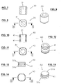
- Fig. 4 a view of a first connecting element in a section along the line IV-IV in Fig. 5
- Fig. 5 a plan view of the connecting element according to Fig. 4
- Fig. 6 a perspective view of the connecting element according to Fig. 4
- Fig. 7 a view of a second connecting element in a section along the line VII-VII in Fig. 8
- FIG. 8 a plan view of the connecting element according to Fig. 7 ;
- Fig. 9 a perspective view of the connecting element according to Fig. 7 ;
- Fig. 10 a view of a third connecting element in a section along the line XX in Fig. 11 ;
- Fig. 11 a plan view of the connecting element according to Fig. 10 ;
- Fig. 12 a perspective view of the connecting element according to Fig. 10 ;
- Fig. 13 a view of a fourth connecting element in a section along the line XIII-XIII in Fig. 14 ;
- Fig. 14 a plan view of the connecting element according to Fig. 13 ;
- Fig. 15 a perspective view of the connecting element according to Fig. 13 ;
- Fig. 15 a perspective view of the connecting element according to Fig. 13 ;
- FIG. 16 a perspective, partially sectioned view of a first arrangement with two interconnected plates
- Fig. 17 a perspective, partially sectioned view of a second arrangement with two interconnected plates
- Fig. 18 a perspective, partially sectioned view of a third arrangement with three interconnected plates
- Fig. 19 a perspective, partially sectioned view of a fourth arrangement with a plurality of interconnected plates
- Fig. 20 a perspective, partially sectioned view of another embodiment of the plate of a kit according to the invention.
- Fig. 1-3 show by way of example a plate 10 of a kit according to the invention.
- the plate 10 is formed substantially parallelepiped-shaped and is provided with through holes 11 which lead from the top of the plate 10 to the underside thereof and which are arranged on a grid.
- the grid is chosen so that the respective center of the through holes 11 are located on the grid points of a square network.
- the grid size, ie the distance D between any two adjacent through-holes 11 is thus constant.
- the in the Fig. 1-3 shown plate 10 has the following dimensions: the length and width correspond to 3D, the height corresponds to D. Of course, these dimensions may be chosen so that they are arbitrary multiples of D. Accordingly, the total number of through holes 11 is different. Through holes 11, which are located at the edge of the plate 10 are removed by a distance of D / 2 of this. If a further plate 10 is now arranged on the top or bottom of the plate 10 or on one of its side surfaces, the distance between any two adjacent through-holes 11 still corresponds to the value D.
- another grid is conceivable instead of a square grid, e.g. a rectangular mesh in which the distance between two through holes 11 which are adjacent to each other in the vertical direction is different from the distance having two horizontally adjacent through holes 11.
- a grid and a polar arrangement is conceivable in which the through holes 11 are each arranged offset by a certain angle on circular lines.
- a through hole 11 does not necessarily have to be arranged on all grid points, but any through holes 11 can be omitted. It is also conceivable to provide further through holes 11, which are not on the grid.
- the through holes 11 are stepped. They comprise a smooth, cylindrical central part and have at the respective ends of countersinks 12a and 12b, which are not cylindrical.
- the cross section of the counterbores 12a, 12b is thus different from a circular shape, whereby a connection element received in the counterbore 12a, 12b can be secured against rotation.
- the cross section of the depressions 12a, 12b has a shape that is substantially square, with the corners being rounded.
- Its cross-section may have, for example, one of the following shapes: essentially a polygon with three, four or more corners, an oval shape, a slot shape, any other shape composed of straight and / or round sections, etc.
- FIGS. 2 and 3 show, 10 holes 13 are mounted on the side surfaces of the plate, which lie on the grid of the through holes 11 and thus have a distance from each other, which corresponds to the grid dimension D.
- the bores 13 are each offset from the outer surfaces of the plate 10 by a counterbore 14 and provided with a thread, which extends into the through hole 11.
- the cross section of the counterbores 14 is the same as that of the counterbores 12a, 12b. However, the depth t of the counterbores 14 need not match the depth T of the counterbores 12a, 12b.
- the through holes 11 are connected by transverse bores 15, which are arranged in the extension of the threaded bores 13, which are located on the front and rear side surface of the plate 10.
- the transverse bores 15 serve for passing a fluid and can also be omitted depending on the intended use of the plate 10.
- Fig. 4-6 show a connecting element 20 which serves as a nut for a fastening screw and is designed in the form of a sleeve with an internal thread 21.
- the shape of the outer surface of the nut 20 is complementary to the shape of the countersink 12a, 12b, 14 chosen.
- the connecting element 20 can be positively and accurately connected to the plate 10 by being inserted into a countersink 12a, 12b, 14. Due to the non-circular shape of the countersink 12a, 12b, 14 and the connecting element 20 this is secured against rotation, for example, when tightened into the internal thread 21 mounting screw is tightened.
- Fig. 7 - 9 show a connecting element 30, which serves as a centering element for positioning two plates and is provided with a smooth through hole 31.
- the outer surfaces of the centering element 30 have the same shape as the nut 20.
- Two plates 10 can be precisely arranged by means of the connecting member 30 in relation to each other by this in two opposing counterbores 12a, 12b, 14 of the two plates 10 is inserted.
- connecting elements can be provided with sealing means.
- Fig. 10 - 12 show a connecting element 40, which serves as a passage element and similar to the connecting element 30 is configured, but is provided with two grooves, in which O-rings 41 are embedded.
- the connecting element 40 can be produced between two plates - except for the passage opening 31 - a sealing connection.
- Fig. 13 - 15 show a connecting element 50, which serves as a closure element and with which a bore 11, 13 of the plate 10 can be sealed.
- the lower part 51b of the connecting element 50 corresponds to the shape of the countersink 12a, 12b, 14.
- the upper part 51a has a groove with an O-ring 41 and is formed in particular closed at the top.
- sealing means there are other types of fasteners with sealing means conceivable, for example, may be provided at the connecting element 20, a sealing ring 41.
- the connecting elements 20, 30, 40, 50 are manufactured at different heights. This ensures that, depending on the reduction 12a, 12b, 14, in which a connecting element 20, 30, 40, 50 is to be inserted, two plates 10 can be seamlessly connected. There are also plates 10 provided in different dimensions.
- connecting elements which are of the type of connecting elements 20, 30, 40, 50, but not on all its outer sides positively against the inner walls of the cuts 12a, 12b, 14, but have a game.
- the outer surfaces may be slightly set back in one direction, so that the connecting element, when inserted into one of the depressions 12a, 12b, 14, has a play in this direction, while in the direction perpendicular thereto exactly in the countersink 12a, 12b, 14 is positioned.
- Such connecting elements with play can e.g. serve to connect two plates so that they are positioned only in one direction exactly to each other, while they are displaced in the other direction relative to each other. It is also conceivable to compensate by means of connecting elements with game deviations, which may have the arrangement of the through holes 11 from the given grid. Such deviations may e.g. Therefore stir that change due to temperature changes, the dimensions of the plate 10. Despite these deviations, two plates can be connected by e.g. in the subsidence 12a, 12b, 14, a connection element without play and one is used with game.
- a connecting element which has a cylindrical cross-section.
- a connecting element is a plate 10th rotated by any angle with a second plate 10 connectable.
- FIGS. 16 and 17 each show an example of an arrangement with two plates 10 of different dimensions.
- the two plates 10 are fixed with fastening screws 60 and nuts 20, wherein in each case in the adjacent depressions 12a and 12b, a centering element 30 is inserted.
- a nut 20 is inserted into which the end of a fastening screw 60 engages on both sides.
- the fastening screws 60 are of known type and formed in different lengths to connect plates 10 seamless.
- the head of a fixing screw 60 is cylindrical and provided with a recess 61, in which a tool for tightening or loosening the fixing screw 60 can engage.
- the recess 61 is e.g. designed as a hexagon socket.
- a plate 10 can also be connected at one of its side surfaces with another plate 10, as in the example according to Fig. 18 is shown.
- centering elements 30 are inserted into the adjacent depressions 12 b and 14 and screwed fastening screws 60 in the threaded holes 13.
- connecting elements 40, 50 makes it possible to seal the bores 11, 13 in the plates 10 in the desired manner and thus to form channels through which a gaseous or liquid fluid can be passed.
- Fig. 19 shows an example in which two plates 10 are connected via a connecting element 40, wherein the lateral depressions of the upper plate 10 are closed with closure elements 50. This results in a fluidic connection of the through hole 11 of the lower plate 10 with the adjacent through hole 11 'of the upper plate 10. This is also fluidly connected via the transverse bore 15 with the opposite through hole 11 ".
- the reductions serve 12a, 12b, 14 for receiving a connecting element 20, 30, 40, 50 and prevent twisting thereof.
- the countersinks 12a and 12b on the top and bottom of the plate 10 also form a recess in which the head of a fastening screw 60 can be accommodated.
- the plates 10 and the connecting elements 20, 30, 40, 50, 60 are made of a material which allows an accurate connection, so that the plates 10 are connectable in a precise relation to each other.
- the material is suitable e.g. Metal like aluminum or steel.
- the depressions 12a, 12b, 14 are e.g. produced by milling.
- the plates 10 need not necessarily be formed in one piece, but can also be made of several parts.
- Fig. 20 The core plate 71 comprises through holes 72 and at the sides threads 73 for forming the threaded holes 13 according to the plate 10.
- the side plates 74 comprise holes 75th , which are adjacent to the threads 73 and part of the threaded holes 13.
- the outer plates 76 are with the reductions 12a, 12b and 14 provided.
- the top and bottom of the core plate 71 is spaced from the outer plates 76, so that the holes 72 and the space between the depressions 12 a and 12 b and the holes 72, the through holes 11 according to the plate 10 form.
- the provision of a material-free gap ensures a particularly lightweight construction of the plate.
- the side plates 74 are made of sheet metal and fixedly connected to the core plate 71, e.g. by gluing or welding.
- the outer plates 76 are made in the form of a development of a cuboid made of sheet metal, and bent so that they embrace the edges of the side plates 74. The edges of the outer plates 76 are finally joined, e.g. by gluing or welding.
- the inventive kit has u.a. the advantage that the provision of countersinks with a non-circular cross section in a simple manner, a recorded connection element can be secured against rotation.
- kits By means of the kit according to the invention arrangements can be constructed in a modular manner, which have precise angles and distances and which can be used for different applications, e.g. for clamping of workpieces in processing and / or measuring machines, as a mounting device, as a jig, etc. It is also conceivable to build a partition with the kit, as used for example in exhibition stands.
Description
- Die vorliegende Erfindung bezieht sich auf einen Bausatz mit mindestens einer Platte gemäss Oberbegriff des Anspruchs 1.
- Mittels eines derartigen Bausatzes kann eine Anordnung aus Platten gebildet werden, welche präzise Winkel und Distanzen aufweist und welche bei Bedarf wieder auseinandergenommen werden kann. Derartige Anordnungen sind verschieden einsetzbar, z.B. als Aufspannvorrichtung für Werkstücke, als Montagevorrichtung, Prüfvorrichtung, etc.
- Aus der
EP 338 460 A2 - Ausgehend von diesem Stand der Technik liegt eine Aufgabe der vorliegenden Erfindung darin, den bekannten Bausatz derart weiterzubilden, dass der Aufbau einer Anordnung vereinfacht wird.
- Ein Bausatz, der diese Aufgabe löst, ist im Anspruch 1 angegeben. Die weiteren Ansprüche geben bevorzugte Ausführungen des Bausatzes an.
- Der erfindungsgemässe Bausatz umfasst mindestens eine Platte, bei welcher beidseitig der Durchgangsbohrungen Senkungen mit einem nicht-kreisförmigen Querschnitt angeordnet sind. Diese Formgebung hat den Vorteil, dass auf einfache Weise Mittel bereitgestellt sind, um ein in der Senkung aufgenommenes Verbindungselement gegen ein Verdrehen zu sichern. Die Handhabung beim Aufbau einer Anordnung ist dadurch vereinfacht. Insbesondere können durch Handhabung eines einzigen Werkzeugs mehrere Platten miteinander verbunden werden.
- Die Erfindung wird im Folgenden anhand eines Ausführungsbeispiels unter Bezugnahme auf Figuren erläutert.
Es zeigen
Fig. 1 eine Draufsicht einer Platte eines erfindungsgemässen Bausatzes;
Fig. 2 eine Seitenansicht der Platte gemässFig. 1 ;
Fig. 3 eine Schnittansicht der Platte gemäss der Linie III-III inFig. 1 ;
Fig. 4 eine Ansicht eines ersten Verbindungselements in einem Schnitt gemäss der Linie IV-IV inFig. 5 ;
Fig. 5 eine Draufsicht des Verbindungselements gemässFig. 4 ;
Fig. 6 eine perspektivische Ansicht des Verbindungselements gemässFig. 4 ;
Fig. 7 eine Ansicht eines zweiten Verbindungselements in einem Schnitt gemäss der Linie VII-VII inFig. 8 ;
Fig. 8 eine Draufsicht des Verbindungselements gemässFig. 7 ;
Fig. 9 eine perspektivische Ansicht des Verbindungselements gemässFig. 7 ;
Fig. 10 eine Ansicht eines dritten Verbindungselements in einem Schnitt gemäss der Linie X-X inFig. 11 ;
Fig. 11 eine Draufsicht des Verbindungselements gemässFig. 10 ;
Fig. 12 eine perspektivische Ansicht des Verbindungselements gemässFig. 10 ;
Fig. 13 eine Ansicht eines vierten Verbindungselements in einem Schnitt gemäss der Linie XIII-XIII inFig. 14 ;
Fig. 14 eine Draufsicht des Verbindungselements gemässFig. 13 ;
Fig. 15 eine perspektivische Ansicht des Verbindungselements gemässFig. 13 ;
Fig. 16 eine perspektivische, teilweise geschnittene Ansicht einer ersten Anordnung mit zwei miteinander verbundenen Platten;
Fig. 17 eine perspektivische, teilweise geschnittene Ansicht einer zweiten Anordnung mit zwei miteinander verbundenen Platten;
Fig. 18 eine perspektivische, teilweise geschnittene Ansicht einer dritten Anordnung mit drei miteinander verbundenen Platten;
Fig. 19 eine perspektivische, teilweise geschnittene Ansicht einer vierten Anordnung mit mehreren miteinander verbundenen Platten; und
Fig. 20 eine perspektivische, teilweise geschnittene Ansicht einer weiteren Ausführungsform der Platte eines erfindungsgemässen Bausatzes. -
Fig. 1 - 3 zeigen beispielhaft eine Platte 10 eines erfindungsgemässen Bausatzes. Die Platte 10 ist im Wesentlichen quaderförmig ausgebildet und ist mit Durchgangsbohrungen 11 versehen, welche von der Oberseite der Platte 10 zu deren Unterseite führen und welche auf einem Raster angeordnet sind. Der Raster ist so gewählt, dass die jeweilige Mitte der Durchgangsbohrungen 11 auf den Gitterpunkten eines quadratischen Netzes liegen. Das Rastermass, d.h. der Abstand D zwischen zwei beliebigen benachbarten Durchgangsbohrungen 11 ist somit konstant. - Die in den
Fig. 1 - 3 dargestellte Platte 10 weist folgende Abmessungen auf: die Länge und Breite entsprechen 3D, die Höhe entspricht D. Natürlich können diese Abmessungen so gewählt sein, dass sie beliebige Vielfache von D sind. Entsprechend ist auch die Gesamtzahl der Durchgangsbohrungen 11 anders. Durchgangsbohrungen 11, welche sich am Rand der Platte 10 befinden, sind um einen Abstand von D/2 von diesem entfernt. Wird nun an der Ober- oder Unterseite der Platte 10 oder an einer ihrer Seitenflächen eine weitere Platte 10 angeordnet, entspricht der Abstand zwischen zwei beliebigen benachbarten Durchgangsbohrungen 11 nach wie vor dem Wert D. - Je nach Anwendungszweck ist anstelle eines quadratischen Netzes auch ein anderer Raster denkbar, z.B. ein rechteckiges Netz, bei welchem der Abstand zwischen zwei Durchgangsbohrungen 11, die in senkrechter Richtung benachbart zueinander sind, verschieden vom Abstand ist, der zwei in waagrechter Richtung benachbarte Durchgangsbohrungen 11 haben. Als Raster ist auch eine polare Anordnung denkbar, bei welcher die Durchgangsbohrungen 11 jeweils um einen bestimmten Winkel versetzt auf Kreislinien angeordnet sind.
- Im Weiteren muss nicht unbedingt auf allen Rasterpunkten eine Durchgangsbohrung 11 angeordnet sein, sondern es können beliebige Durchgangsbohrungen 11 weggelassen werden. Es ist auch denkbar, weitere Durchgangsbohrungen 11 vorzusehen, die nicht auf dem Raster liegen.
- Wie insbesondere
Fig. 3 zeigt, sind die Durchgangsbohrungen 11 abgestuft ausgebildet. Sie umfassen einen glatten, zylindrischen Mittelteil und weisen an den jeweiligen Enden Senkungen 12a und 12b auf, die nicht zylindrisch sind. Der Querschnitt der Senkungen 12a, 12b ist somit von einer kreisrunden Form verschieden, wodurch ein in der Senkung 12a, 12b aufgenommenes Verbindungselement gegen ein Verdrehen gesichert werden kann. - Im hier gezeigten Ausführungsbeispiel hat der Querschnitt der Senkungen 12a, 12b eine Form, die im Wesentlichen quadratisch ist, wobei die Ecken abgerundet sind. Es sind mannigfache nicht-kreisförmige Formen denkbar zur Bildung der Senkung 12a, 12b. Ihr Querschnitt kann z.B. eine der folgenden Formen haben: im Wesentlichen ein Polygon mit drei, vier oder mehr Ecken, ovale Form, Form eines Langlochs, eine beliebig andere Form, die sich aus geraden und/oder runden Abschnitten zusammensetzt, etc.
- Wie insbesondere
Fig. 2 und 3 zeigen, sind an den Seitenflächen der Platte 10 Bohrungen 13 angebracht, die auf dem Raster der Durchgangsbohrungen 11 liegen und somit einen Abstand voneinander haben, der dem Rastermass D entspricht. Die Bohrungen 13 sind gegenüber den Aussenflächen der Platte 10 jeweils durch eine Senkung 14 abgesetzt und mit einem Gewinde versehen, welches bis in die Durchgangsbohrung 11 hineinreicht. Der Querschnitt der Senkungen 14 ist gleich wie derjenige der Senkungen 12a, 12b. Die Tiefe t der Senkungen 14 braucht jedoch nicht mit der Tiefe T der Senkungen 12a, 12b übereinzustimmen. - Wie in
Fig. 1 durch die gestrichelten Linien angedeutet, sind die Durchgangsbohrungen 11 durch Querbohrungen 15 verbunden, welche in der Verlängerung der Gewindebohrungen 13 angeordnet sind, die sich an der vorderen und hinteren Seitenfläche der Platte 10 befinden. Die Querbohrungen 15 dienen zum Durchleiten eines Fluids und können je nach Anwendungszweck der Platte 10 auch weggelassen werden. - Um die Platte 10 mit einer anderen Platte derselben Art zu verbinden, sind verschiedene Verbindungselemente vorgesehen.
-
Fig. 4 - 6 zeigen ein Verbindungselement 20, welches als Mutter für eine Befestigungsschraube dient und in Form einer Hülse mit einem Innengewinde 21 ausgebildet ist. Die Form der Aussenfläche der Mutter 20 ist komplementär zur Form der Senkung 12a, 12b, 14 gewählt. Dadurch ist das Verbindungselement 20 formschlüssig und passgenau mit der Platte 10 verbindbar, indem es in eine Senkung 12a, 12b, 14 eingefügt wird. Aufgrund der nicht-kreisförmigen Gestalt der Senkung 12a, 12b, 14 und des Verbindungselements 20 ist dieses gegen ein Verdrehen gesichert, z.B. dann, wenn eine in das Innengewinde 21 greifende Befestigungsschraube festgezogen wird. -
Fig. 7 - 9 zeigen ein Verbindungselement 30, welches als Zentrierelement zur Positionierung zweier Platten dient und mit einer glatten Durchgangsbohrung 31 versehen ist. Die Aussenflächen des Zentrierelements 30 haben dieselbe Form wie die Mutter 20. Zwei Platten 10 können mittels des Verbindungselements 30 präzise in Relation zueinander angeordnet werden, indem dieses in zwei gegenüberliegenden Senkungen 12a, 12b, 14 der beiden Platten 10 eingefügt wird. - Zur Bildung einer Anordnung, welche auch im Gebiet der Fluidtechnik einsetzbar ist, können Verbindungselemente mit Dichtmitteln vorgesehen sein.
-
Fig. 10 - 12 zeigen ein Verbindungselement 40, welches als Durchgangselement dient und ähnlich wie das Verbindungselement 30 ausgestaltet ist, jedoch mit zwei Nuten versehen ist, in welche O-Ringe 41 eingelassen sind. Mittels des Verbindungselements 40 kann zwischen zwei Platten - bis auf die Durchgangsöffnung 31 - eine dichtende Verbindung erzeugt werden. -
Fig. 13 - 15 zeigen ein Verbindungselement 50, welches als Verschlusselement dient und mit welchem eine Bohrung 11, 13 der Platte 10 dicht verschlossen werden kann. Der untere Teil 51b des Verbindungselements 50 entspricht der Form der Senkung 12a, 12b, 14. Der obere Teil 51a weist eine Nut mit einem O-Ring 41 auf und ist insbesondere an der Oberseite geschlossen ausgebildet. - Es sind weitere Arten von Verbindungselementen mit Dichtmitteln denkbar, beispielsweise kann beim Verbindungselement 20 ein Dichtring 41 vorgesehen sein.
- Zur Bildung eines Bausatzes sind die Verbindungselemente 20, 30, 40, 50 in verschiedenen Höhen gefertigt. Dadurch ist gewährleistet, dass je nach Senkung 12a, 12b, 14, in welche ein Verbindungselement 20, 30, 40, 50 eingefügt werden soll, zwei Platten 10 fugenlos verbunden werden können. Es sind auch Platten 10 in unterschiedlichen Abmessungen vorgesehen.
- Es können auch Verbindungselemente vorgesehen sein, welche von der Art der Verbindungselemente 20, 30, 40, 50 sind, jedoch nicht an allen ihren Aussenseiten formschlüssig an den Innenwänden der Senkungen 12a, 12b, 14 anliegen, sondern ein Spiel aufweisen. Beispielsweise können die Aussenflächen in einer Richtung etwas zurückversetzt gestaltet sein, sodass das Verbindungselement, wenn es in eine der Senkungen 12a, 12b, 14 eingesetzt ist, in dieser Richtung ein Spiel aufweist, währenddessen es in der Richtung senkrecht dazu genau in der Senkung 12a, 12b, 14 positioniert ist.
- Derartige Verbindungselemente mit Spiel können z.B. dazu dienen, zwei Platten so zu verbinden, dass sie nur in einer Richtung genau zueinander positioniert sind, währenddessen sie in der anderen Richtung relativ zueinander verschiebbar sind. Es ist auch denkbar, mittels Verbindungselementen mit Spiel Abweichungen auszugleichen, welche die Anordnung der Durchgangsbohrungen 11 vom vorgegebenen Raster aufweisen kann. Derartige Abweichungen können z.B. daher rühren, dass aufgrund von Temperaturveränderungen die Abmessungen der Platte 10 ändern. Trotz diesen Abweichungen können zwei Platten verbunden werden, indem z.B. in die Senkungen 12a, 12b, 14 ein Verbindungselement ohne Spiel und eines mit Spiel eingesetzt wird.
- Als weitere Ausführungsform ist ein Verbindungselement denkbar, welches einen zylindrischen Querschnitt aufweist. Mit einem derartigen Verbindungselement ist eine Platte 10 um einen beliebigen Winkel gedreht mit einer zweiten Platte 10 verbindbar.
-
Fig. 16 und 17 zeigen jeweils ein Beispiel einer Anordnung mit zwei Platten 10 unterschiedlicher Abmessungen. Bei der Anordnung gemässFig. 16 sind die beiden Platten 10 mit Befestigungsschrauben 60 und Muttern 20 befestigt, wobei jeweils in den anliegenden Senkungen 12a und 12b jeweils ein Zentrierelement 30 eingefügt ist. Bei der Anordnung gemässFig. 17 ist in den anliegenden Senkungen 12a und 12b eine Mutter 20 eingefügt, in welche beidseitig jeweils das Ende einer Befestigungsschraube 60 greift. - Die Befestigungsschrauben 60 sind bekannter Art und in unterschiedlicher Länge ausgebildet, um Platten 10 fugenlos verbinden zu können. Der Kopf einer Befestigungsschraube 60 ist zylindrisch ausgestaltet und mit einer Vertiefung 61 versehen, in welche ein Werkzeug zum Festziehen oder Lösen der Befestigungsschraube 60 greifen kann. Die Vertiefung 61 ist z.B. als Innensechskant ausgebildet.
- Mittels der Gewindebohrungen 13 kann eine Platte 10 auch an einer ihrer Seitenflächen mit einer anderen Platte 10 verbunden werden, wie dies im Beispiel gemäss
Fig. 18 gezeigt ist. Zum Verbinden werden Zentrierelemente 30 in die anliegenden Senkungen 12b und 14 eingefügt und Befestigungsschrauben 60 in den Gewindebohrungen 13 festgeschraubt. - Die Verwendung der Verbindungselemente 40, 50 erlaubt es, die Bohrungen 11, 13 in den Platten 10 in gewünschter Weise abzudichten und somit als Kanäle auszubilden, durch welche ein gasförmiges oder flüssiges Fluid geleitetet werden kann.
-
Fig. 19 zeigt ein Beispiel, bei welchem zwei Platten 10 über ein Verbindungselement 40 verbunden sind, wobei die seitlichen Senkungen der oberen Platte 10 mit Verschlusselementen 50 verschlossen sind. Es ergibt sich somit ein fluidische Verbindung der Durchgangsbohrung 11 der unteren Platte 10 mit der anliegenden Durchgangsbohrung 11' der oberen Platte 10. Diese ist über die Querbohrung 15 ebenfalls fluidisch mit der gegenüberliegenden Durchgangsbohrung 11" verbunden. - Wie aus den Beispielen gemäss
Fig. 16 - 19 ersichtlich, dienen die Senkungen 12a, 12b, 14 zur Aufnahme eines Verbindungselements 20, 30, 40, 50 und verhindern ein Verdrehen derselben. Die Senkungen 12a und 12b an der Ober- und Unterseite der Platte 10 bilden ebenfalls eine Aussparung, in welcher der Kopf einer Befestigungsschraube 60 aufnehmbar ist. - Die Platten 10 und die Verbindungselemente 20, 30, 40, 50, 60 sind aus einem Material gefertigt, welche ein genaue Verbindung erlauben, sodass die Platten 10 in einer präzisen Relation zueinander verbindbar sind. Als Material eignet sich z.B. Metall wie Aluminium oder Stahl. Die Senkungen 12a, 12b, 14 sind z.B. durch Fräsen herstellbar.
- Die Platten 10 brauchen nicht unbedingt einteilig ausgebildet sein, sondern können auch aus mehreren Teilen gefertigt werden.
Fig. 20 zeigt eine Variante einer mehrteiligen Platte 70. Diese umfasst eine Kernplatte 71, vier Seitenplatten 74 sowie Aussenplatten 76. Die Kernplatte 71 umfasst durchgehende Löcher 72 sowie an den Seiten Gewinde 73 zur Bildung der Gewindebohrungen 13 gemäss der Platte 10. Die Seitenplatten 74 umfassen Löcher 75, welche an die Gewinde 73 angrenzen und Teil der Gewindebohrungen 13 sind. Die Aussenplatten 76 sind mit den Senkungen 12a, 12b und 14 versehen. Die Ober- und Unterseite der Kernplatte 71 ist beabstandet zu den Aussenplatten 76 angeordnet, sodass die Löcher 72 und der Zwischenraum zwischen den Senkungen 12a bzw. 12b und den Löchern 72 die Durchgangsbohrungen 11 gemäss der Platte 10 bilden. Das Vorsehen eines materialfreien Zwischenraums gewährleistet einen besonders leichten Aufbau der Platte. - Zur Herstellung der Platte 70 werden die Seitenplatten 74 aus Blech gefertigt und mit der Kernplatte 71 fest verbunden, z.B. durch Kleben oder Schweissen. Die Aussenplatten 76 werden in Form einer Abwicklung eines Quaders aus Blech hergestellt, und derart gebogen, dass sie die Ränder der Seitenplatten 74 umgreifen. Die Ränder der Aussenplatten 76 werden schliesslich zusammengefügt, z.B. durch Kleben oder Schweissen.
- Der erfindungsgemässe Bausatz hat u.a. den Vorteil, dass das Vorsehen von Senkungen mit einem nicht-kreisförmigen Querschnitt auf einfache Weise, ein aufgenommenes Verbindungselement gegen ein Verdrehen gesichert werden kann.
- Mittels des erfindungsgemässen Bausatz können Anordnungen modulartig aufgebaut, die präzise Winkel und Distanzen aufweisen und die für verschiedene Anwendungen verwendbar sind, z.B. zum Aufspannen von Werkstücken in Bearbeitungs- und/oder Messmaschinen, als Montagevorrichtung, als Aufspannvorrichtung, etc. Es ist auch denkbar, mit dem Bausatz eine Trennwand aufzubauen, wie sie beispielsweise in Messeständen verwendet wird.
Claims (10)
- Bausatz mit mindestens einer Platte (10; 70), welche auf einem Raster angeordnete Durchgangsbohrungen (11; 72) und
beidseitig der Durchgangsbohrungen angeordnete Senkungen (12a, 12b) zur Aufnahme eines Verbindungselements umfasst, dadurch gekennzeichnet, dass
der Querschnitt der Senkungen (12a, 12b) von einer kreisrunden Form abweicht, um ein in einer Senkung aufgenommenes Verbindungselement (20, 30, 40, 50) gegen ein Verdrehen zu sichern. - Bausatz nach Anspruch 1, wobei der Querschnitt der Senkungen (12a, 12b) eine Form aufweist, die gerade Abschnitte umfasst.
- Bausatz nach einem der vorangehenden Ansprüche, wobei die Seitenflächen der Platte (10; 70) mit Gewindebohrungen (13; 73, 75) versehen sind.
- Bausatz nach Anspruch 3, wobei an dem einen Ende der Gewindebohrungen (13; 73, 75) Senkungen (14) angeordnet sind, deren Form mit der Form der Senkungen (12a, 12b) der Durchgangsbohrungen (11) übereinstimmt.
- Bausatz nach einem der vorangehenden Ansprüche, wobei der Raster quadratisch mit einem Rastermass D ist und wobei die Länge, Breite und/oder Höhe der Platte (10; 70) ein Vielfaches von D beträgt.
- Bausatz nach einem der vorangehenden Ansprüche, mit mindestens einem Verbindungselement (20, 30, 40, 50), welches formschlüssig in die Senkungen (12a, 12b, 14) einfügbar ist.
- Bausatz nach Anspruch 6, wobei das Verbindungselement (20, 30, 40) als Hülse ausgebildet ist.
- Bausatz nach Anspruch 6 oder 7, wobei das Verbindungselement (20) ein Innengewinde (21) aufweist.
- Bausatz nach einem der Ansprüche 6 bis 8, wobei das Verbindungselement (40, 50) ein Dichtmittel (41) umfasst.
- Bausatz nach einem der vorangehenden Ansprüche, wobei die Platte (70) eine Kernplatte (71) mit Löchern (72) zur Bildung der Durchgangsbohrungen und Aussenplatten (76) umfasst, in welchen die Senkungen (12a, 12b) geformt sind, wobei die Senkungen beabstandet zur Kernplatte angeordnet sind.
Priority Applications (7)
| Application Number | Priority Date | Filing Date | Title |
|---|---|---|---|
| DE502006002600T DE502006002600D1 (de) | 2006-09-20 | 2006-09-20 | Bausatz mit mindestens einer Platte |
| DK06405396T DK1902814T3 (da) | 2006-09-20 | 2006-09-20 | Byggesæt med mindst en plade |
| PT06405396T PT1902814E (pt) | 2006-09-20 | 2006-09-20 | Conjunto de elementos construtivos com, pelo menos, uma placa |
| EP06405396A EP1902814B1 (de) | 2006-09-20 | 2006-09-20 | Bausatz mit mindestens einer Platte |
| AT06405396T ATE419955T1 (de) | 2006-09-20 | 2006-09-20 | Bausatz mit mindestens einer platte |
| ES06405396T ES2318710T3 (es) | 2006-09-20 | 2006-09-20 | Kit de construccion comprendiendo al menos una placa. |
| US11/843,831 US8033537B2 (en) | 2006-09-20 | 2007-08-23 | Construction set comprising at least one plate |
Applications Claiming Priority (1)
| Application Number | Priority Date | Filing Date | Title |
|---|---|---|---|
| EP06405396A EP1902814B1 (de) | 2006-09-20 | 2006-09-20 | Bausatz mit mindestens einer Platte |
Publications (2)
| Publication Number | Publication Date |
|---|---|
| EP1902814A1 EP1902814A1 (de) | 2008-03-26 |
| EP1902814B1 true EP1902814B1 (de) | 2009-01-07 |
Family
ID=37575119
Family Applications (1)
| Application Number | Title | Priority Date | Filing Date |
|---|---|---|---|
| EP06405396A Active EP1902814B1 (de) | 2006-09-20 | 2006-09-20 | Bausatz mit mindestens einer Platte |
Country Status (7)
| Country | Link |
|---|---|
| US (1) | US8033537B2 (de) |
| EP (1) | EP1902814B1 (de) |
| AT (1) | ATE419955T1 (de) |
| DE (1) | DE502006002600D1 (de) |
| DK (1) | DK1902814T3 (de) |
| ES (1) | ES2318710T3 (de) |
| PT (1) | PT1902814E (de) |
Families Citing this family (16)
| Publication number | Priority date | Publication date | Assignee | Title |
|---|---|---|---|---|
| ES2318710T3 (es) * | 2006-09-20 | 2009-05-01 | Konstruktionsburo Wuthrich | Kit de construccion comprendiendo al menos una placa. |
| SE532109C2 (sv) * | 2008-01-17 | 2009-10-27 | Flexprop Ab | Hållare för positionering och lägesfixering av arbetsstycke och förfarande för dess tillverkning |
| CN101791766B (zh) * | 2010-01-07 | 2012-04-18 | 沈阳飞机工业(集团)有限公司 | 孔系通用基础支承连接板 |
| WO2012112789A1 (en) * | 2011-02-16 | 2012-08-23 | Robert Graham | Modular building system |
| CN102335870B (zh) * | 2011-10-20 | 2015-11-18 | 无锡海特精密模具有限公司 | 磨床装夹治具 |
| US20130108355A1 (en) * | 2011-10-28 | 2013-05-02 | John T.S. Lee | Joint device for rods and panels |
| CN102990351B (zh) * | 2012-11-30 | 2016-04-06 | 江苏大学 | 一种螺栓垫片装配装置 |
| US20140178143A1 (en) * | 2012-12-21 | 2014-06-26 | Rajalampi Oy | Workpiece abutment structure for a milling machine |
| US10197216B2 (en) * | 2013-03-11 | 2019-02-05 | University Of North Carolina At Charlotte | Modular kit for construction of apparatus including positioning mechanisms |
| KR20150100165A (ko) * | 2014-02-24 | 2015-09-02 | 주식회사 로보빌더 | 모듈러 액츄에이터 결합장치 |
| US9441654B2 (en) * | 2014-06-03 | 2016-09-13 | Modern Industries, Inc. | Precision positioning and fastening system |
| CN204277526U (zh) * | 2014-10-15 | 2015-04-22 | 富鼎电子科技(嘉善)有限公司 | 夹持装置 |
| US9220993B1 (en) * | 2015-09-01 | 2015-12-29 | Ahmad A. A. A. Alsaleh | Set of construction panels |
| WO2017175138A1 (en) * | 2016-04-04 | 2017-10-12 | Verus Precision Limited | A universal modular fixture system |
| USD853455S1 (en) * | 2016-11-09 | 2019-07-09 | Octofrost Ab | Freezer, part of |
| CN107982937B (zh) * | 2018-01-02 | 2019-05-31 | 东莞市微石塑胶金属科技有限公司 | 拼接结构件 |
Family Cites Families (39)
| Publication number | Priority date | Publication date | Assignee | Title |
|---|---|---|---|---|
| US683184A (en) * | 1901-06-27 | 1901-09-24 | James P Rockwell | Clamp. |
| US724116A (en) * | 1902-11-20 | 1903-03-31 | Henry A Maley | Plate-holder for printing-presses. |
| US2076207A (en) * | 1936-01-28 | 1937-04-06 | Laurence C Powell | Distortion check for welding apparatus |
| US2621807A (en) * | 1948-01-29 | 1952-12-16 | Edmund H Rendich | Display positioning device |
| GB1239218A (de) * | 1967-08-22 | 1971-07-14 | ||
| CH587099A5 (de) * | 1974-02-21 | 1977-04-29 | Mauser Schaerer Gmbh | |
| DE2903706A1 (de) * | 1979-01-31 | 1980-08-14 | Kraftwerk Union Ag | Verdrehsicherung fuer in ein bauteil eingeschraubte kopfschrauben |
| US4310963A (en) * | 1980-04-23 | 1982-01-19 | Rudi Blumle | Method for the fabrication of an apparatus for the close fitting positioning of workpieces to be machined |
| US4598453A (en) * | 1984-12-21 | 1986-07-08 | E. I. Du Pont De Nemours And Company | Apparatus for centering and aligning a workpiece |
| US4828240A (en) * | 1986-09-02 | 1989-05-09 | Te-Co. | Workpiece securing apparatus for a machine tool |
| DE3812942A1 (de) * | 1988-04-19 | 1989-11-09 | Heckler & Koch Gmbh | Verbindungselement zum verbinden von elementen eines bauelementesatzes, bauelement und bausatz fuer werkstueckhalterungen |
| DE4311965A1 (de) * | 1993-04-10 | 1994-10-13 | Klaus Dr Ing Thormeier | Werkbank, insbesondere als Lehrmittel in der Form einer ergonomisch gestalteten Mehrzweck-Werkbank |
| JP3178978B2 (ja) * | 1994-10-24 | 2001-06-25 | 株式会社イマオコーポレーション | 取付補助部材 |
| US5887733A (en) * | 1996-04-19 | 1999-03-30 | Omni Structures International, Inc. | Modular tower tooling system |
| US6022009A (en) * | 1997-05-09 | 2000-02-08 | Northrop Grumman Corporation | Top load threaded bolt assembly |
| DE29821418U1 (de) * | 1998-12-01 | 2000-04-20 | Witte Horst Entwicklung | Grundplatte zum Aufbau von Vorrichtungen zum Aufbau von Werkstücken |
| US6279888B1 (en) * | 1999-04-26 | 2001-08-28 | Wal, Iii H. James Vander | Modular tooling system with radial base platform |
| US6047958A (en) * | 1999-06-30 | 2000-04-11 | Active Automation, Inc. | Adjustable pallet |
| US6158104A (en) * | 1999-08-11 | 2000-12-12 | General Electric Co. | Assembly jig for use with integrally covered bucket blades |
| AU2001268032A1 (en) * | 2000-03-08 | 2001-09-17 | University Of Maryland | Modular platform assembly |
| US6293534B1 (en) * | 2000-04-12 | 2001-09-25 | David F. Leban | Support device with floating pins |
| DE20119047U1 (de) * | 2001-11-22 | 2002-02-21 | Kahl Helmut | Hohlkammerprofilsystem für Präzisionsaufbauten |
| US7036810B2 (en) * | 2002-02-01 | 2006-05-02 | Wal Iii H James Vander | Modular tooling apparatus with tapered locater system |
| DE20202108U1 (de) * | 2002-02-13 | 2003-06-26 | Witte Horst Entwicklung | Sandwichplatte zum Aufbau von Werkstück-Aufspannvorrichtungen |
| US7517269B2 (en) * | 2003-08-12 | 2009-04-14 | Parvia Corp. | Building element for constructing a modular substructure |
| US7083166B1 (en) * | 2003-10-01 | 2006-08-01 | Durfee David L | Light-weight, modular work-holding chassis |
| JP4326982B2 (ja) * | 2004-02-18 | 2009-09-09 | ヤマザキマザック株式会社 | 加工治具 |
| US7686553B2 (en) * | 2004-08-27 | 2010-03-30 | Durfee Jr David L | Precision positioning and fastening system |
| DE202004014974U1 (de) * | 2004-09-23 | 2006-02-02 | Horst Witte Entwicklungs- Und Vertriebs-Kg | Strebe oder Aufnahmeteil mit rechtwinkligem Querschnitt für ein System zum Aufbau von Vorrichtungen zum Aufspannen von Werkstücken |
| USD563768S1 (en) * | 2005-01-04 | 2008-03-11 | Marino Paul W | Grid bar for modular fixturing |
| ITTO20050183A1 (it) * | 2005-03-18 | 2006-09-19 | Giochi Puliti Srl | Elemento modulare di forma quadrata di sporgenze che consentono il collegamento ad incastro con altri elementi modulari al fine di realizzare un gioco di costruzione |
| US20080160875A1 (en) * | 2005-08-15 | 2008-07-03 | Boaz Leicht | Interconnectible Building Elements For Intellectual Challenge Games |
| DE102006022264B4 (de) * | 2006-05-11 | 2008-04-03 | Uhlmann Pac-Systeme Gmbh & Co. Kg | Siegelwerkzeug zum Siegeln von Folien in einer Siegelstation |
| US8408962B2 (en) * | 2006-06-05 | 2013-04-02 | Melissa C. Sambenedetto | Toy construction system having a variable angle joint |
| ES2318710T3 (es) * | 2006-09-20 | 2009-05-01 | Konstruktionsburo Wuthrich | Kit de construccion comprendiendo al menos una placa. |
| US7637488B2 (en) * | 2007-02-07 | 2009-12-29 | Lingdong Zeng | Multiple purposes cutting board |
| US7722059B1 (en) * | 2007-09-28 | 2010-05-25 | Marino Paul W | Complete wheel bracket assembly for a modular base assembly for vehicle model making |
| US20090140111A1 (en) * | 2007-11-30 | 2009-06-04 | Marino Paul W | Actuator bracket for a modular base assembly for vehicle model making |
| US7735816B2 (en) * | 2007-12-10 | 2010-06-15 | Hashim Paul R | Carve smart |
-
2006
- 2006-09-20 ES ES06405396T patent/ES2318710T3/es active Active
- 2006-09-20 AT AT06405396T patent/ATE419955T1/de active
- 2006-09-20 PT PT06405396T patent/PT1902814E/pt unknown
- 2006-09-20 EP EP06405396A patent/EP1902814B1/de active Active
- 2006-09-20 DK DK06405396T patent/DK1902814T3/da active
- 2006-09-20 DE DE502006002600T patent/DE502006002600D1/de active Active
-
2007
- 2007-08-23 US US11/843,831 patent/US8033537B2/en not_active Expired - Fee Related
Also Published As
| Publication number | Publication date |
|---|---|
| DK1902814T3 (da) | 2009-04-14 |
| PT1902814E (pt) | 2009-03-25 |
| ATE419955T1 (de) | 2009-01-15 |
| DE502006002600D1 (de) | 2009-02-26 |
| ES2318710T3 (es) | 2009-05-01 |
| US20080070469A1 (en) | 2008-03-20 |
| US8033537B2 (en) | 2011-10-11 |
| EP1902814A1 (de) | 2008-03-26 |
Similar Documents
| Publication | Publication Date | Title |
|---|---|---|
| EP1902814B1 (de) | Bausatz mit mindestens einer Platte | |
| DE10326928A1 (de) | Schnittstelle zwischen zwei Teilelementen eines Werkzeugsystems | |
| DE202017107404U1 (de) | Knotenverbinder für Profilsysteme oder dergleichen | |
| EP1729018B1 (de) | Profilverbindungssystem | |
| EP1141562B1 (de) | Verbindungseinrichtung zum anschluss eines ersten werkstückes an ein zweites werkstück | |
| EP2852768B1 (de) | Befestigungsvorrichtung | |
| DE19825426B4 (de) | In eine T-Nut einsetzbarer Näherungsschalter bzw. Befestigungselement dafür | |
| DE4126991C2 (de) | Stab mit einer Verbindungsanordnung | |
| DE3422222A1 (de) | Gestell aus einem profilstab und daran mit einem verbinder angebrachter platte o. dgl. gestellteil | |
| DE3231114A1 (de) | Verbindungssystem | |
| EP4240979A1 (de) | Profilkopplungsanordnung | |
| EP0545078B1 (de) | Aufspannvorrichtung für Werkzeugmaschinen | |
| EP1621283B1 (de) | System zum Aufbau von Vorrichtungen zum Aufspannen von Werkstücken | |
| CH633621A5 (en) | Structural element set for connecting in each case two profiles which abut against one another at any angle | |
| DE10119548A1 (de) | Strebeneinrichtung | |
| DE19713236C2 (de) | Verbindungsteil zur Vormontage einer Schraube | |
| DE202007008969U1 (de) | Profilverbinder sowie Profilverbund | |
| DE3822622C2 (de) | ||
| EP0987450B1 (de) | Verbindungseinrichtung zum Verbinden von Profilstäben | |
| DE202008015601U1 (de) | System zum Aufbauen einer Vorrichtung zum Aufspannen von Werkstücken | |
| EP3636841A1 (de) | Montagevorrichtung für ein einbauelement | |
| DE102012014686A1 (de) | Bauteilesystem zur Herstellung einer lösbaren Verbindung von Bauelementen | |
| DE3728324A1 (de) | Klemmelement und daraus zusammengesetzte beschlaege zum loesbaren verbinden von plattenfoermigen gebilden fuer freie und vorwaehlbare winkelstellungen | |
| EP1227253B1 (de) | Vorrichtung für die Verbindung zweier Werkstücke | |
| DE19842896A1 (de) | Verbindungseinrichtung zum Verbinden von Profilstäben |
Legal Events
| Date | Code | Title | Description |
|---|---|---|---|
| PUAI | Public reference made under article 153(3) epc to a published international application that has entered the european phase |
Free format text: ORIGINAL CODE: 0009012 |
|
| AK | Designated contracting states |
Kind code of ref document: A1 Designated state(s): AT BE BG CH CY CZ DE DK EE ES FI FR GB GR HU IE IS IT LI LT LU LV MC NL PL PT RO SE SI SK TR |
|
| AX | Request for extension of the european patent |
Extension state: AL BA HR MK YU |
|
| 17P | Request for examination filed |
Effective date: 20080714 |
|
| GRAP | Despatch of communication of intention to grant a patent |
Free format text: ORIGINAL CODE: EPIDOSNIGR1 |
|
| AKX | Designation fees paid |
Designated state(s): AT BE BG CH CY CZ DE DK EE ES FI FR GB GR HU IE IS IT LI LT LU LV MC NL PL PT RO SE SI SK TR |
|
| GRAS | Grant fee paid |
Free format text: ORIGINAL CODE: EPIDOSNIGR3 |
|
| GRAA | (expected) grant |
Free format text: ORIGINAL CODE: 0009210 |
|
| AK | Designated contracting states |
Kind code of ref document: B1 Designated state(s): AT BE BG CH CY CZ DE DK EE ES FI FR GB GR HU IE IS IT LI LT LU LV MC NL PL PT RO SE SI SK TR |
|
| REG | Reference to a national code |
Ref country code: GB Ref legal event code: FG4D Free format text: NOT ENGLISH |
|
| REG | Reference to a national code |
Ref country code: CH Ref legal event code: EP |
|
| REG | Reference to a national code |
Ref country code: CH Ref legal event code: NV Representative=s name: AMMANN PATENTANWAELTE AG BERN |
|
| REG | Reference to a national code |
Ref country code: IE Ref legal event code: FG4D Free format text: LANGUAGE OF EP DOCUMENT: GERMAN |
|
| REF | Corresponds to: |
Ref document number: 502006002600 Country of ref document: DE Date of ref document: 20090226 Kind code of ref document: P |
|
| REG | Reference to a national code |
Ref country code: PT Ref legal event code: SC4A Free format text: AVAILABILITY OF NATIONAL TRANSLATION Effective date: 20090317 |
|
| REG | Reference to a national code |
Ref country code: DK Ref legal event code: T3 |
|
| REG | Reference to a national code |
Ref country code: SE Ref legal event code: TRGR |
|
| REG | Reference to a national code |
Ref country code: ES Ref legal event code: FG2A Ref document number: 2318710 Country of ref document: ES Kind code of ref document: T3 |
|
| PG25 | Lapsed in a contracting state [announced via postgrant information from national office to epo] |
Ref country code: SI Free format text: LAPSE BECAUSE OF FAILURE TO SUBMIT A TRANSLATION OF THE DESCRIPTION OR TO PAY THE FEE WITHIN THE PRESCRIBED TIME-LIMIT Effective date: 20090107 |
|
| PG25 | Lapsed in a contracting state [announced via postgrant information from national office to epo] |
Ref country code: LT Free format text: LAPSE BECAUSE OF FAILURE TO SUBMIT A TRANSLATION OF THE DESCRIPTION OR TO PAY THE FEE WITHIN THE PRESCRIBED TIME-LIMIT Effective date: 20090107 Ref country code: FI Free format text: LAPSE BECAUSE OF FAILURE TO SUBMIT A TRANSLATION OF THE DESCRIPTION OR TO PAY THE FEE WITHIN THE PRESCRIBED TIME-LIMIT Effective date: 20090107 |
|
| REG | Reference to a national code |
Ref country code: IE Ref legal event code: FD4D |
|
| PG25 | Lapsed in a contracting state [announced via postgrant information from national office to epo] |
Ref country code: IS Free format text: LAPSE BECAUSE OF FAILURE TO SUBMIT A TRANSLATION OF THE DESCRIPTION OR TO PAY THE FEE WITHIN THE PRESCRIBED TIME-LIMIT Effective date: 20090507 Ref country code: LV Free format text: LAPSE BECAUSE OF FAILURE TO SUBMIT A TRANSLATION OF THE DESCRIPTION OR TO PAY THE FEE WITHIN THE PRESCRIBED TIME-LIMIT Effective date: 20090107 Ref country code: PL Free format text: LAPSE BECAUSE OF FAILURE TO SUBMIT A TRANSLATION OF THE DESCRIPTION OR TO PAY THE FEE WITHIN THE PRESCRIBED TIME-LIMIT Effective date: 20090107 |
|
| PG25 | Lapsed in a contracting state [announced via postgrant information from national office to epo] |
Ref country code: IE Free format text: LAPSE BECAUSE OF FAILURE TO SUBMIT A TRANSLATION OF THE DESCRIPTION OR TO PAY THE FEE WITHIN THE PRESCRIBED TIME-LIMIT Effective date: 20090107 Ref country code: CZ Free format text: LAPSE BECAUSE OF FAILURE TO SUBMIT A TRANSLATION OF THE DESCRIPTION OR TO PAY THE FEE WITHIN THE PRESCRIBED TIME-LIMIT Effective date: 20090107 Ref country code: EE Free format text: LAPSE BECAUSE OF FAILURE TO SUBMIT A TRANSLATION OF THE DESCRIPTION OR TO PAY THE FEE WITHIN THE PRESCRIBED TIME-LIMIT Effective date: 20090107 |
|
| PLBE | No opposition filed within time limit |
Free format text: ORIGINAL CODE: 0009261 |
|
| STAA | Information on the status of an ep patent application or granted ep patent |
Free format text: STATUS: NO OPPOSITION FILED WITHIN TIME LIMIT |
|
| PG25 | Lapsed in a contracting state [announced via postgrant information from national office to epo] |
Ref country code: RO Free format text: LAPSE BECAUSE OF FAILURE TO SUBMIT A TRANSLATION OF THE DESCRIPTION OR TO PAY THE FEE WITHIN THE PRESCRIBED TIME-LIMIT Effective date: 20090107 Ref country code: SK Free format text: LAPSE BECAUSE OF FAILURE TO SUBMIT A TRANSLATION OF THE DESCRIPTION OR TO PAY THE FEE WITHIN THE PRESCRIBED TIME-LIMIT Effective date: 20090107 |
|
| 26N | No opposition filed |
Effective date: 20091008 |
|
| PG25 | Lapsed in a contracting state [announced via postgrant information from national office to epo] |
Ref country code: BG Free format text: LAPSE BECAUSE OF FAILURE TO SUBMIT A TRANSLATION OF THE DESCRIPTION OR TO PAY THE FEE WITHIN THE PRESCRIBED TIME-LIMIT Effective date: 20090407 |
|
| PG25 | Lapsed in a contracting state [announced via postgrant information from national office to epo] |
Ref country code: MC Free format text: LAPSE BECAUSE OF NON-PAYMENT OF DUE FEES Effective date: 20090930 |
|
| PG25 | Lapsed in a contracting state [announced via postgrant information from national office to epo] |
Ref country code: GR Free format text: LAPSE BECAUSE OF FAILURE TO SUBMIT A TRANSLATION OF THE DESCRIPTION OR TO PAY THE FEE WITHIN THE PRESCRIBED TIME-LIMIT Effective date: 20090408 |
|
| PG25 | Lapsed in a contracting state [announced via postgrant information from national office to epo] |
Ref country code: LU Free format text: LAPSE BECAUSE OF NON-PAYMENT OF DUE FEES Effective date: 20090920 |
|
| PG25 | Lapsed in a contracting state [announced via postgrant information from national office to epo] |
Ref country code: HU Free format text: LAPSE BECAUSE OF FAILURE TO SUBMIT A TRANSLATION OF THE DESCRIPTION OR TO PAY THE FEE WITHIN THE PRESCRIBED TIME-LIMIT Effective date: 20090708 |
|
| PG25 | Lapsed in a contracting state [announced via postgrant information from national office to epo] |
Ref country code: TR Free format text: LAPSE BECAUSE OF FAILURE TO SUBMIT A TRANSLATION OF THE DESCRIPTION OR TO PAY THE FEE WITHIN THE PRESCRIBED TIME-LIMIT Effective date: 20090107 |
|
| PG25 | Lapsed in a contracting state [announced via postgrant information from national office to epo] |
Ref country code: CY Free format text: LAPSE BECAUSE OF FAILURE TO SUBMIT A TRANSLATION OF THE DESCRIPTION OR TO PAY THE FEE WITHIN THE PRESCRIBED TIME-LIMIT Effective date: 20090107 |
|
| PGFP | Annual fee paid to national office [announced via postgrant information from national office to epo] |
Ref country code: DK Payment date: 20140919 Year of fee payment: 9 |
|
| PGFP | Annual fee paid to national office [announced via postgrant information from national office to epo] |
Ref country code: AT Payment date: 20140911 Year of fee payment: 9 Ref country code: FR Payment date: 20140919 Year of fee payment: 9 Ref country code: GB Payment date: 20140919 Year of fee payment: 9 Ref country code: SE Payment date: 20140918 Year of fee payment: 9 Ref country code: ES Payment date: 20140926 Year of fee payment: 9 |
|
| PGFP | Annual fee paid to national office [announced via postgrant information from national office to epo] |
Ref country code: IT Payment date: 20140926 Year of fee payment: 9 Ref country code: PT Payment date: 20140320 Year of fee payment: 9 |
|
| PGFP | Annual fee paid to national office [announced via postgrant information from national office to epo] |
Ref country code: NL Payment date: 20140918 Year of fee payment: 9 |
|
| PGFP | Annual fee paid to national office [announced via postgrant information from national office to epo] |
Ref country code: BE Payment date: 20140919 Year of fee payment: 9 |
|
| REG | Reference to a national code |
Ref country code: PT Ref legal event code: MM4A Free format text: LAPSE DUE TO NON-PAYMENT OF FEES Effective date: 20160321 |
|
| REG | Reference to a national code |
Ref country code: DK Ref legal event code: EBP Effective date: 20150930 |
|
| PG25 | Lapsed in a contracting state [announced via postgrant information from national office to epo] |
Ref country code: IT Free format text: LAPSE BECAUSE OF NON-PAYMENT OF DUE FEES Effective date: 20150920 |
|
| REG | Reference to a national code |
Ref country code: SE Ref legal event code: EUG |
|
| REG | Reference to a national code |
Ref country code: AT Ref legal event code: MM01 Ref document number: 419955 Country of ref document: AT Kind code of ref document: T Effective date: 20150920 |
|
| GBPC | Gb: european patent ceased through non-payment of renewal fee |
Effective date: 20150920 |
|
| PG25 | Lapsed in a contracting state [announced via postgrant information from national office to epo] |
Ref country code: PT Free format text: LAPSE BECAUSE OF NON-PAYMENT OF DUE FEES Effective date: 20160321 Ref country code: SE Free format text: LAPSE BECAUSE OF NON-PAYMENT OF DUE FEES Effective date: 20150921 |
|
| REG | Reference to a national code |
Ref country code: NL Ref legal event code: MM Effective date: 20151001 |
|
| REG | Reference to a national code |
Ref country code: FR Ref legal event code: ST Effective date: 20160531 |
|
| PG25 | Lapsed in a contracting state [announced via postgrant information from national office to epo] |
Ref country code: GB Free format text: LAPSE BECAUSE OF NON-PAYMENT OF DUE FEES Effective date: 20150920 |
|
| PG25 | Lapsed in a contracting state [announced via postgrant information from national office to epo] |
Ref country code: AT Free format text: LAPSE BECAUSE OF NON-PAYMENT OF DUE FEES Effective date: 20150920 Ref country code: FR Free format text: LAPSE BECAUSE OF NON-PAYMENT OF DUE FEES Effective date: 20150930 Ref country code: NL Free format text: LAPSE BECAUSE OF NON-PAYMENT OF DUE FEES Effective date: 20151001 |
|
| PG25 | Lapsed in a contracting state [announced via postgrant information from national office to epo] |
Ref country code: DK Free format text: LAPSE BECAUSE OF NON-PAYMENT OF DUE FEES Effective date: 20150930 |
|
| PG25 | Lapsed in a contracting state [announced via postgrant information from national office to epo] |
Ref country code: ES Free format text: LAPSE BECAUSE OF NON-PAYMENT OF DUE FEES Effective date: 20150921 |
|
| PG25 | Lapsed in a contracting state [announced via postgrant information from national office to epo] |
Ref country code: BE Free format text: LAPSE BECAUSE OF NON-PAYMENT OF DUE FEES Effective date: 20150930 |
|
| REG | Reference to a national code |
Ref country code: ES Ref legal event code: FD2A Effective date: 20180706 |
|
| PGFP | Annual fee paid to national office [announced via postgrant information from national office to epo] |
Ref country code: DE Payment date: 20230920 Year of fee payment: 18 |
|
| PGFP | Annual fee paid to national office [announced via postgrant information from national office to epo] |
Ref country code: CH Payment date: 20231001 Year of fee payment: 18 |