EP1901201B1 - Lesegerät für RF-Etiketten - Google Patents
Lesegerät für RF-Etiketten Download PDFInfo
- Publication number
- EP1901201B1 EP1901201B1 EP07113200A EP07113200A EP1901201B1 EP 1901201 B1 EP1901201 B1 EP 1901201B1 EP 07113200 A EP07113200 A EP 07113200A EP 07113200 A EP07113200 A EP 07113200A EP 1901201 B1 EP1901201 B1 EP 1901201B1
- Authority
- EP
- European Patent Office
- Prior art keywords
- information
- identification information
- tag
- replaced
- error
- Prior art date
- Legal status (The legal status is an assumption and is not a legal conclusion. Google has not performed a legal analysis and makes no representation as to the accuracy of the status listed.)
- Expired - Fee Related
Links
Images


Classifications
-
- G—PHYSICS
- G06—COMPUTING; CALCULATING OR COUNTING
- G06K—GRAPHICAL DATA READING; PRESENTATION OF DATA; RECORD CARRIERS; HANDLING RECORD CARRIERS
- G06K17/00—Methods or arrangements for effecting co-operative working between equipments covered by two or more of main groups G06K1/00 - G06K15/00, e.g. automatic card files incorporating conveying and reading operations
-
- H—ELECTRICITY
- H04—ELECTRIC COMMUNICATION TECHNIQUE
- H04L—TRANSMISSION OF DIGITAL INFORMATION, e.g. TELEGRAPHIC COMMUNICATION
- H04L1/00—Arrangements for detecting or preventing errors in the information received
- H04L1/12—Arrangements for detecting or preventing errors in the information received by using return channel
- H04L1/16—Arrangements for detecting or preventing errors in the information received by using return channel in which the return channel carries supervisory signals, e.g. repetition request signals
- H04L1/18—Automatic repetition systems, e.g. Van Duuren systems
- H04L1/1829—Arrangements specially adapted for the receiver end
- H04L1/1835—Buffer management
- H04L1/1838—Buffer management for semi-reliable protocols, e.g. for less sensitive applications such as streaming video
-
- G—PHYSICS
- G06—COMPUTING; CALCULATING OR COUNTING
- G06K—GRAPHICAL DATA READING; PRESENTATION OF DATA; RECORD CARRIERS; HANDLING RECORD CARRIERS
- G06K7/00—Methods or arrangements for sensing record carriers, e.g. for reading patterns
- G06K7/0008—General problems related to the reading of electronic memory record carriers, independent of its reading method, e.g. power transfer
-
- H—ELECTRICITY
- H04—ELECTRIC COMMUNICATION TECHNIQUE
- H04B—TRANSMISSION
- H04B5/00—Near-field transmission systems, e.g. inductive loop type
Definitions
- the present invention relates to wireless communications performed between RF tags and RF tag readers, and more particularly to an RF tag reader and a method performed by the RF tag reader.
- RF tags radio frequency tags
- readers or reader/writers
- a reader/writer can read information from an RF tag and write information into an RF tag.
- a reader/writer is also referred to as an interrogator.
- An RF tag is also referred to as a wireless tag, an RFID, an RFID tag, an IC tag, an electronic tag, etc.
- RF tags are generally categorized into active types and passive types.
- An active type RF tag is capable of generating power by itself, and therefore, the configuration of the RF tag reader can be simplified.
- a passive type RF tag cannot generate power by itself, and therefore, it receives energy from the outside to perform operations such as sending ID information.
- the passive type RF tag is preferable in terms of reducing cost, and holds great potential for the future.
- the electromagnetic coupling type uses frequency bandwidths of a few KHz or around 13.5 MHz.
- the electromagnetic wave type uses a UHF band (e.g., 950 MHz) or a high frequency bandwidth of around 2.45 GHz. In terms of increasing the communication range, signals of high frequencies are preferably used.
- RF tags In a system employing RF tags, some kind of data such as identification information (UID) is read from and written into RF tags to manage products, cargo, etc.
- RF tags can be appropriately used for various purposes other than managing products. For example, information indicating some kind of value such as a ticket or points can be read from and written into an RF tag.
- RF tags can also be used as electronic tickets or railway tickets in next-generation transportation systems, or as electronic money, etc.
- communications between an RF tag and an RF tag reader are performed in a one-on-one manner, and communications with multiple RF tags are performed by a time division multiplex (TDM) method (one-on-one communication is performed in each time slot).
- TDM time division multiplex
- the RF tag reader In communications with an individual RF tag, the RF tag reader first sends a response request signal the RF tag, and then the RF tag responds by returning a packet including a UID. The RF tag reader determines whether there is an error in the packet. If there is no error, the RF tag reader processes the information received, and starts communicating with the next RF tag. If an error is detected in the received packet, the RF tag reader sends a resend request signal to the RF tag to resend the packet.
- TDM time division multiplex
- the RF tag resends the packet including the UID in response to the resend request signal. In this manner, appropriate information is collected from each and every one of the RF tags.
- the operations of detecting errors and resending information performed in communications between RF tag and the RF tag reader are described, for example, in standard ISO/IEC FDIS 18000-6: 2004 (E).
- Identification information (UID) stored and sent by each RF tag accompanying a management object includes, for example, an ISO header, an IC manufacturer code, a company code, a product code, and a product serial number.
- each UID is unique to an individual management object; however, part of the UID can be common to particular management objects.
- one or more of the ISO header, the IC manufacturer code, the company code, and the product code may be common to multiple management objects.
- information for example, the company code
- the company code is common to multiple management objects, and thus cannot be used for the purpose of distinguishing one product from another. In the event that a company code is necessary for some particular signal process, the company code can be easily acquired according to need because it is already known.
- a packet is resent regardless of which part of the UID includes the error.
- the RF tag reader may request the RF tag to resend the packet in the event that an error is detected in the company code.
- the RF tag resends the entire packet including the UID. That is, if information necessary for distinguishing the product from others is properly received but an error is found in the information unnecessary for distinguishing the product, the entire packet is resent.
- the RF tag indiscriminately resends parts of the packet that do not really need to be resent. This increases the time required for reading information of each RF tag, which leads to degraded throughput.
- the present invention provides an RF tag reader and method in which one or more of the above-described disadvantages are eliminated, and reduces the number of times that an RF tag reader requests an RF tag to resend a packet.
- An RF tag reader determines whether an error can be detected in identification information (UID) received from an RF tag, after the identification information is partially replaced with predetermined data.
- UID identification information
- An error is never detected in the predetermined information, and therefore, a resend request would never be made due to an error in the predetermined information. Accordingly, the number of times that the RF tag reader requests the RF tag to resend the identification information can be reduced compared to the conventional technology.
- the identification information includes individual information that is unique to a specific management object accompanied by the RF tag and individual classification information that is common to unspecified management objects.
- the individual information is essential for identifying a management object.
- the individual classification information other than the individual information is known to the RF tag reader, and does not affect the process of identifying the management object.
- the individual classification information can include appropriate items according to the purpose or the user.
- the number of bits to be replaced in the individual classification information can be varied. All or part of the identification classification information received from the RF tag can be replaced with the predetermined information. A continuous series of bits or intermittent series of bits in the identification information received from the RF tag can be replaced with predetermined information.
- the technique according to an embodiment of the present invention can be realized with hardware or both software and hardware.
- FIG. 1 is a functional block diagram of a reader/writer (or RF tag reader) according to an embodiment of the present invention.
- FIG. 1 illustrates an antenna 102, a frequency sharing unit 104, an amplifier 106, a demodulator 108, a local oscillator 110, a decoder 112, a replacing unit 114, a replacement data generating/saving unit 116, a reception data replacing unit 118, a CRC determining unit 120, a control circuit 122, a CRC addition unit 124, an encoder 126, a modulator 128, and an amplifier 130.
- the frequency sharing unit 104 separates transmission signals and reception signals communicated via the antenna 102.
- the amplifier 106 appropriately adjusts power of reception signals received by the reader/writer.
- the demodulator 108 performs frequency conversion, demodulation, filtering, etc., on reception signals.
- the local oscillator 110 supplies a local oscillator frequency to the demodulator 108 and the modulator 128.
- the decoder 112 decodes the encoded reception signals.
- the replacing unit 114 includes the replacement data generating/saving unit 116 and the reception data replacing unit 118.
- the replacement data generating/saving unit 116 holds or generates predetermined replacement data.
- the predetermined replacement data is appropriately specified according to the purpose for which the reader/writer is to be used. For example, one or more of an ISO header, an IC manufacturer code, a company code, and a product code can be used as the replacement data.
- the reception data replacing unit 118 replaces part of the data in a reception signal with the replacement data. Details of operations of the replacing unit 114 are described below.
- the CRC determining unit 120 determines whether there is an error in a reception signal including replacement data.
- the CRC determining unit 120 determines whether there is an error by a cyclic redundancy check (CRC) method in the present embodiment; however, any appropriate error check method can be employed.
- CRC cyclic redundancy check
- the control circuit 122 controls the operations of the elements in the reader/writer.
- One or more of the elements in the reader/writer are software; the control circuit 122 can be realized with hardware or both software and hardware.
- the CRC addition unit 124 adds a CRC check bit to the transmission signal.
- appropriate information for the employed method is added to the transmission signal for the purpose of error checking.
- the encoder 126 encodes transmission signals.
- the modulator 128 performs frequency conversion, modulation, filtering, etc., on transmission signals.
- the amplifier 130 appropriately adjusts the power of transmission signals.
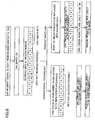
- FIG. 2 is a flowchart of the operation of the reader/writer according to the embodiment of the present invention.
- step S1 the reader/writer sends a response request signal to a nearby RF tag. Communications between an RF tag and the reader/writer are performed in a one-on-one manner. Communications with multiple RF tags are performed by the TDM method, where one-on-one communication is performed in each time slot.
- step S2 signals (data) transmitted by the RF tag in response to the response request signal are received by the reader/writer.
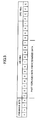
- FIG. 3 illustrates an example of a signal transmitted by the RF tag.
- the signal includes preamble bits, identification information (UID), and CRC bits. In the example shown in FIG. 3 , these are represented by hexadecimal digits except for the preamble bits.
- the preamble bits include information pertaining to overhead, which is determined by the employed communication protocol.
- the identification information includes an ISO header, an IC manufacturer code, a company code, a product code, and a serial number. These are merely examples of identification information; any other appropriate signal format can be employed in the present invention.
- the IC manufacture code indicates the manufacture of the integrated circuit (LSI) included in the RF tag.
- the company code indicates the entity that manages the products using the RF tags.
- the product code distinguishes the type of the management object accompanied by the RF tag.
- the management object can be, for example, a television set, a personal computer, or any other object that is to be managed.
- the serial number indicates information unique to each management object, such as a production number of the product.
- the CRC bits are added to be used for error checking. In the present embodiment, a particular calculation is performed on all of the 64 bits representing the identification information (UID), and the calculation result is added as the CRC bits. That is, the entire identification information (UID) is the object of error checking.
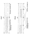
- FIG. 4 illustrates an example of a signal received by the reader/writer.
- the serial number in the identification information UID
- the IC manufacturer code, the company code, and the product code were not received properly due to a disturbance in the wireless environment.
- the management object accompanied by the RF tag is a particular product of a particular company (for example, a television set sold by company A).
- the ISO header, the IC manufacturer code, the company code, and the product code are common to all management objects; only the serial number is different for each management object.
- information unique to a specific management object accompanied by an RF tag is referred to as "individual information” and information common to unspecified management objects is referred to as "individual classification information”.
- the ISO header, the IC manufacturer code, the company code, and the product code are individual classification information
- the serial number is individual information.
- the individual classification information can include information such as an International Standard Book Number (ISBN), and the individual number can include a number uniquely given to a book at the discretion of the book store managing the inventory.
- the individual classification information is already known to the reader/writer, which is assumed to be saved in the replacement data generating/saving unit 116 shown in FIG. 1 as known data.
- the individual classification information can be stored beforehand as known data or can be generated separately by some method.
- FIG. 5 illustrates the reception data after the individual classification information in the reception data is replaced with the replacement data available in the reader/writer.
- the reception data after replacement corresponds to the output signal from the reception data replacing unit 118 shown in FIG. 1 .
- step S4 shown in FIG. 2 an error check is performed to check all of the identification information (UID) in the reception data after correction (after replacement). More specifically, a particular known calculation is performed in the reader/writer to check all 64 bits representing the corrected identification information (UID) ( FIG. 5 ). The error check is performed by determining whether the calculation result coincides with the received CRC bits.
- the flow proceeds to step S5.
- an error in the individual classification information which is information other than the serial number in the identification information (UID)
- step S5 the reader/writer transmits a resend request signal, requesting the RF tag to resend the identification information (UID).
- the RF tag resends the identification information (UID), and the flow returns to step S2. The above-described steps are repeated.
- step S6 it is confirmed whether identification information is obtained from all RF tags. If there is an unprocessed RF tag, the flow returns to step S1, and the above-described steps are repeated for the unprocessed RF tag. If there are no unprocessed RF tags remaining, the flow ends.
- FIG. 6 is a diagram for describing the difference between the embodiment of the present invention and a conventional example.
- the parts relevant to the present embodiment are substantially the same as the procedure shown in FIG. 2 .
- the reader/writer transmits a signal requesting UID to the tag.
- the tag transmits the UID.
- the CRC check is immediately performed on the reception data. No matter which part of the UID includes an error, the CRC check result indicates an error (NG). Thus, CRC errors occur frequently, and resend requests are made frequently.
- part of the reception data is replaced by known data (individual classification information), and the CRC check is performed on the data after the replacement.
- the replaced parts would never cause an error, and therefore, the CRC check results would often indicate OK. If the CRC check result indicates NG, it is because there is an error in the individual information. In this case, it is really necessary to resend the information.
- the number of times of resending the information is reduced, and the information is resent only when it is really necessary.
- the ISO header, the IC manufacturer code, the company code, and the product code are common to all management objects, and correspond to the individual classification information. Meanwhile, only the serial number is different for each management object, and corresponds to the individual information.
- the compositions of the individual classification information and the individual information are not limited thereto.
- the ISO header, the IC manufacturer code, and the company code can correspond to the individual classification information
- the product code and the serial number can correspond to the individual information.
- contents of the individual classification information and the individual information do not have to be fixed; they can be appropriately changed according to the circumstances or the user.
- the number of bits in the individual classification information to be replaced can be changed according to the purpose for which the reader/writer is used, the time period during which the reader/writer is used, the user of the reader/writer, or for any other reason.
- the number of bits of the individual classification information is preferably small (zero bits in the extreme case), although the number of times of resending the identification information would be increased.
- the number of bits of the individual classification information is preferably large.
- information items such as "company code” and "product code” many not necessarily be replaced all at once in the present embodiment. For example, only the top two bits of the product code may be common to multiple management objects. In the serial number, some bits may common to multiple management objects. Therefore, the number of bits in the identification information to be replaced may depend not only on information items but also on units of bits.
- a continuous series of bits in the identification information received from the RF tag is replaced by predetermined information.
- an intermittent series of bits in the identification information received from the RF tag can be replaced by predetermined information.
- the present embodiment is applicable to signals of various formats.
Claims (14)
- RF-Etikettenleser mit:einer Empfangseinheit (102, 104, 106, 108, 110, 112), die konfiguriert ist, um von einem RF-Etikett Daten zu empfangen, die wenigstens Identifikationsinformationen umfassen, die einen ersten Teil und einen zweiten Teil enthalten;einer Fehlerbestimmungseinheit (120), die konfiguriert ist, um zu bestimmen, ob in den empfangenen Daten ein Fehler vorhandenen ist; undeiner Sendeeinheit (102, 104, 110, 126, 128, 130), die konfiguriert ist, um eine Aufforderung an das RF-Etikett zu senden, um die Daten noch einmal zu schicken, falls ein Fehler in den empfangenen Daten detektiert wird;dadurch gekennzeichnet, dassder Leser ferner umfasst:eine Austauscheinheit (114), die konfiguriert ist, um den ersten Teil der Identifikationsinformationen gegen vorbestimmte Informationen auszutauschen, wodurch die Identifikationsinformationen in teilweise ausgetauschte Identifikationsinformationen verwandelt werden,welche vorbestimmten Informationen Informationen umfassen, die im RF-Etikettenleser gespeichert sind oder erzeugt werden;bei dem die Fehlerbestimmungseinheit (120) konfiguriert ist, um einen Fehlerbestimmungsprozess an den teilweise ausgetauschten Identifikationsinformationen auszuführen; undbei dem die vorbestimmten Informationen so sind, dass dann, wenn der zweite Teil der Identifikationsinformationen korrekt empfangen wird, die Fehlerbestimmungseinheit in den teilweise ausgetauschten Identifikationsinformationen keinen Fehler detektiert,bei dem die teilweise ausgetauschten Identifikationsinformationen die vorbestimmten Informationen enthalten, die gegen den ersten Teil ausgetauscht wurden, sowie den korrekt empfangenen zweiten Teil.
- RF-Etikettenleser nach Anspruch 1, bei dem:der erste Teil der Identifikationsinformationen individuelle Klassifizierungsinformationen umfasst, die unspezifizierten Verwaltungsobjekten gemeinsam sind, und der zweite Teil der Identifikationsinformationen wenigstens individuelle Informationen umfasst, die für ein spezifisches Verwaltungsobjekt, das durch das RF-Etikett begleitet wird, einzigartig sind.
- RF-Etikettenleser nach Anspruch 2, bei dem:alle oder ein Teil der individuellen Klassifizierungsinformationen, die von dem RF-Etikett empfangen werden, gegen die vorbestimmten Informationen ausgetauscht werden.
- RF-Etikettenleser nach Anspruch 3, bei dem:eine Anzahl von Bits in den individuellen Klassifizierungsinformationen, welche Bits gegen die vorbestimmten Informationen ausgetauscht werden, variabel ist.
- RF-Etikettenleser nach Anspruch 1, bei dem:der erste Teil der Identifikationsinformationen eine Bitfolge umfasst.
- RF-Etikettenleser nach Anspruch 1, bei dem:der erste Teil der Identifikationsinformationen eine unterbrochene Bitfolge umfasst.
- RF-Etikettenleser nach Anspruch 1, bei dem:die vorbestimmten Informationen bekannte Informationen umfassen, die in einem Speicher gespeichert sind.
- RF-Etikettenleser nach Anspruch 1, bei dem:die vorbestimmten Informationen Informationen umfassen, die durch den RF-Etikettenleser erzeugt werden.
- RF-Etikettenleser nach Anspruch 1, bei dem:die Fehlerbestimmungseinheit (120) konfiguriert ist, um durch ein zyklisches Blocksicherungsverfahren zu bestimmen, ob ein Fehler detektiert werden kann.
- RF-Etikettenleser nach Anspruch 1, bei dem:die Identifikationsinformationen wenigstens eine laufende Nummer eines Verwaltungsobjektes, einen Typ des Verwaltungsobjektes und einen Firmencode umfassen.
- Verfahren, das durch einen RF-Etikettenleser angewendet wird, welches Verfahren die Schritte umfasst:Empfangen, von einem RF-Etikett, von Daten, die wenigstens Identifikationsinformationen umfassen (S2), die einen ersten Teil und einen zweiten Teil enthalten:Ausführen eines Fehlerbestimmungsschrittes (S4), um zu bestimmen, ob in den empfangenen Daten ein Fehler vorhanden ist; undSenden einer Aufforderung an das RF-Etikett, um die Daten noch einmal zu schicken, falls ein Fehler in den empfangenen Daten detektiert wird (S5),gekennzeichnet durch den Schritt:Austauschen des ersten Teils der Identifikationsinformationen gegen vorbestimmte Informationen (S3), wodurch die Identifikationsinformationen in teilweise ausgetauschte Identifikationsinformationen verwandelt werden, welche vorbestimmten Informationen Informationen umfassen, die im RF-Etikettenleser gespeichert sind oder erzeugt werden;bei, dem der Fehlerbestimmungsschritt an den teilweise ausgetauschten Identifikationsinformationen ausgeführt wird; undbei dem die vorbestimmten Informationen so sind, dass dann, wenn der zweite Teil der Identifikationsinformationen korrekt empfangen wird, der Fehlerbestimmungsschritt in den teilweise ausgetauschten Identifikationsinformationen keinen Fehler detektiert,bei dem die teilweise ausgetauschten Identifikationsinformationen die vorbestimmten Informationen enthalten, die gegen den ersten Teil ausgetauscht wurden, sowie den korrekt empfangenen zweiten Teil.
- Verfahren nach Anspruch 11, bei dem:der erste Teil der Identifikationsinformationen individuelle Klassifizierungsinformationen umfasst, die unspezifizierten Verwaltungsobjekten gemeinsam sind, und der zweite Teil der Identifikationsinformationen individuelle Informationen umfasst, die für ein spezifisches Verwaltungsobjekt, das durch das RF-Etikett begleitet wird, einzigartig sind.
- Verfahren nach Anspruch 12, bei dem:alle oder ein Teil der individuellen Klassifizierungsinformationen, die von dem RF-Etikett empfangen werden, gegen die vorbestimmten Informationen ausgetauscht werden.
- Verfahren nach Anspruch 13, bei dem:eine Anzahl von Bits in den individuellen Klassifizierungsinformationen, welche Bits gegen die vorbestimmten Informationen ausgetauscht werden, gemäß einer Umgebung, in der die Daten empfangen werden, variabel ist.
Applications Claiming Priority (1)
| Application Number | Priority Date | Filing Date | Title |
|---|---|---|---|
| JP2006251448A JP4984774B2 (ja) | 2006-09-15 | 2006-09-15 | Rfタグリーダ及び再送制御方法 |
Publications (2)
| Publication Number | Publication Date |
|---|---|
| EP1901201A1 EP1901201A1 (de) | 2008-03-19 |
| EP1901201B1 true EP1901201B1 (de) | 2010-11-17 |
Family
ID=38626501
Family Applications (1)
| Application Number | Title | Priority Date | Filing Date |
|---|---|---|---|
| EP07113200A Expired - Fee Related EP1901201B1 (de) | 2006-09-15 | 2007-07-26 | Lesegerät für RF-Etiketten |
Country Status (7)
| Country | Link |
|---|---|
| US (1) | US20080068134A1 (de) |
| EP (1) | EP1901201B1 (de) |
| JP (1) | JP4984774B2 (de) |
| KR (1) | KR100901621B1 (de) |
| CN (1) | CN101159025B (de) |
| DE (1) | DE602007010560D1 (de) |
| TW (1) | TWI383323B (de) |
Families Citing this family (9)
| Publication number | Priority date | Publication date | Assignee | Title |
|---|---|---|---|---|
| EP1988469B1 (de) * | 2006-02-24 | 2012-07-04 | Fujitsu Ltd. | Fehlersteuereinrichtung |
| US7963443B2 (en) * | 2007-12-31 | 2011-06-21 | Vivotech, Inc. | Systems, methods, and computer program products for mitigating signal noise at a wireless smart device reader |
| TWI410874B (zh) * | 2009-01-07 | 2013-10-01 | Mstar Semiconductor Inc | 搜尋射頻識別標籤之方法及射頻識別讀取器 |
| JP5172752B2 (ja) * | 2009-03-23 | 2013-03-27 | 株式会社日立製作所 | Rfタグリーダ回路 |
| WO2010114526A1 (en) * | 2009-03-31 | 2010-10-07 | Hewlett-Packard Development Company, L.P. | System for recovering data from an unreadable tag |
| EP2495690B1 (de) * | 2011-03-01 | 2015-05-13 | Nxp B.V. | Transponder und Verfahren zur Überwachung des Zugriffs auf Anwendungsdaten im Transponder |
| CN102509200B (zh) * | 2011-09-26 | 2014-07-30 | 四川省宜宾惠美线业有限责任公司 | 仓储物资条码标识解析容错纠错方法 |
| EP2958056B1 (de) | 2014-06-20 | 2019-02-20 | Nxp B.V. | Funkfrequenztransponderschaltung |
| JP6615625B2 (ja) * | 2016-01-22 | 2019-12-04 | 東芝テック株式会社 | 無線タグ通信装置 |
Family Cites Families (17)
| Publication number | Priority date | Publication date | Assignee | Title |
|---|---|---|---|---|
| JPH0620108A (ja) * | 1992-07-01 | 1994-01-28 | Tokimec Inc | 非接触データキャリアを用いたデータ処理装置 |
| KR100593474B1 (ko) * | 1998-12-17 | 2006-07-03 | 에스케이 텔레콤주식회사 | 이동통신망에서의 메시지 중복 전송 방법 및 그를 이용한단말기에서의 중복 메시지 처리 방법 |
| JP3297668B2 (ja) * | 2000-04-26 | 2002-07-02 | 松下電器産業株式会社 | 符号/復号化装置及び符号/復号化方法 |
| US7103096B2 (en) * | 2000-10-12 | 2006-09-05 | 3Com Corporation | Performance evaluation of multicarrier channels with forward error correction and automatic retransmission request |
| US6975206B2 (en) * | 2002-08-30 | 2005-12-13 | Intellectual Property, Llc | Method for communication between central terminal and multiple transponders |
| US7272778B2 (en) * | 2002-09-27 | 2007-09-18 | International Business Machines Corporation | Method and systems for improving test of data transmission in multi-channel systems |
| US20040081119A1 (en) * | 2002-10-28 | 2004-04-29 | Zhun Zhong | Reducing packet drop in IEEE 802.11 handoff by packet forwarding using driver image queue |
| US7333479B2 (en) * | 2003-06-30 | 2008-02-19 | Nokia Corporation | RFID system with packetized data storage in a mobile environment: methods, systems and program products |
| JP4453077B2 (ja) * | 2004-04-06 | 2010-04-21 | ブラザー工業株式会社 | 無線タグ通信システムの質問器 |
| US7405660B2 (en) * | 2005-03-24 | 2008-07-29 | Impinj, Inc. | Error recovery in RFID reader systems |
| US7336175B2 (en) * | 2004-05-13 | 2008-02-26 | Cisco Technology, Inc. | Methods and devices for locating and uniquely provisioning RFID devices |
| JP2006023963A (ja) * | 2004-07-07 | 2006-01-26 | Fujitsu Ltd | 無線icタグリーダライタ、無線icタグシステムおよび無線icタグデータ書込方法 |
| JP2006067160A (ja) * | 2004-08-26 | 2006-03-09 | Fujitsu Ltd | 無線タグシステム、無線タグアクセス制御装置、無線タグアクセス制御方法、無線タグアクセス制御プログラム、及び無線タグ |
| JP2007094773A (ja) | 2005-09-29 | 2007-04-12 | Nec Electronics Corp | Icタグ、icタグシステム及びそのデータ通信方法 |
| EP3379352A1 (de) * | 2005-10-28 | 2018-09-26 | Mojix, Inc. | Erkennung einer datenfolge aus einer folge von symbolen |
| US20070126585A1 (en) * | 2005-12-06 | 2007-06-07 | Symbol Technologies, Inc. | System integration of RFID and MIMO technologies |
| US7667574B2 (en) * | 2006-12-14 | 2010-02-23 | Corning Cable Systems, Llc | Signal-processing systems and methods for RFID-tag signals |
-
2006
- 2006-09-15 JP JP2006251448A patent/JP4984774B2/ja not_active Expired - Fee Related
-
2007
- 2007-07-26 DE DE602007010560T patent/DE602007010560D1/de active Active
- 2007-07-26 EP EP07113200A patent/EP1901201B1/de not_active Expired - Fee Related
- 2007-07-27 TW TW096127520A patent/TWI383323B/zh not_active IP Right Cessation
- 2007-07-30 US US11/882,034 patent/US20080068134A1/en not_active Abandoned
- 2007-08-20 CN CN2007101465379A patent/CN101159025B/zh not_active Expired - Fee Related
- 2007-08-22 KR KR1020070084424A patent/KR100901621B1/ko not_active IP Right Cessation
Also Published As
| Publication number | Publication date |
|---|---|
| EP1901201A1 (de) | 2008-03-19 |
| TWI383323B (zh) | 2013-01-21 |
| KR100901621B1 (ko) | 2009-06-08 |
| KR20080025296A (ko) | 2008-03-20 |
| JP2008071281A (ja) | 2008-03-27 |
| US20080068134A1 (en) | 2008-03-20 |
| DE602007010560D1 (de) | 2010-12-30 |
| CN101159025A (zh) | 2008-04-09 |
| JP4984774B2 (ja) | 2012-07-25 |
| CN101159025B (zh) | 2010-06-09 |
| TW200813857A (en) | 2008-03-16 |
Similar Documents
| Publication | Publication Date | Title |
|---|---|---|
| EP1901201B1 (de) | Lesegerät für RF-Etiketten | |
| US9165170B1 (en) | RFID tag dynamically adjusting clock frequency | |
| US8222997B2 (en) | Method of preventing collisions between RFID readers in RFID system | |
| US8543056B2 (en) | Communication device, communication method, and program | |
| EP2417753B1 (de) | Verfahren zur detektion einer nfc-vorrichtung durch emulierung mehrerer kontaktloser karten, die eine vielzahl von protokollen verwenden können | |
| US8577295B2 (en) | Method and apparatus for data communication between a base station and a transponder | |
| US8193912B1 (en) | RFID tag dynamically adjusting clock frequency | |
| US20070236335A1 (en) | Ahead-of-time scheduling of commands in RFID reader systems | |
| CN101796528A (zh) | 回射有限标签 | |
| KR101545477B1 (ko) | Rfid 시스템의 구동 프로그램 업그레이드 방법 | |
| JP2008536439A (ja) | 多重プロトコルによるデータ通信のための非接触式icカード及びその通信方法 | |
| US20070069865A1 (en) | IC tag, IC tag system, and data communicating method for the IC tag | |
| US8321743B2 (en) | Information storage medium and information storage medium processing apparatus | |
| US10931331B2 (en) | Communication device and method | |
| US20100102925A1 (en) | Passive Tag And Radio Frequency Identification System Utilizing The Same | |
| JP4572894B2 (ja) | 無線タグリーダ | |
| US20100164687A1 (en) | Rfid reader and identification method for identifying the same | |
| KR101112535B1 (ko) | 태그 내 플래그를 이용한 단말기 인증 방법 | |
| WO2021103115A1 (zh) | 一种rfid标签数据输出的方法、装置、设备和存储介质 | |
| US20040178274A1 (en) | Contactless radio frequency magnetic field data transmission card and its application system | |
| CN113285925A (zh) | 一种基于低成本柔性印刷标签的通信协议 | |
| CN117597977A (zh) | 传输速率确定方法及通信装置 | |
| Elrharbi et al. | RFID Communication Modes | |
| KR20110053779A (ko) | 스마트 카드에서의 rf통신 처리용 데이터 관리 방법 및 그 스마트 카드 |
Legal Events
| Date | Code | Title | Description |
|---|---|---|---|
| PUAI | Public reference made under article 153(3) epc to a published international application that has entered the european phase |
Free format text: ORIGINAL CODE: 0009012 |
|
| AK | Designated contracting states |
Kind code of ref document: A1 Designated state(s): AT BE BG CH CY CZ DE DK EE ES FI FR GB GR HU IE IS IT LI LT LU LV MC MT NL PL PT RO SE SI SK TR |
|
| AX | Request for extension of the european patent |
Extension state: AL BA HR MK YU |
|
| 17P | Request for examination filed |
Effective date: 20080328 |
|
| 17Q | First examination report despatched |
Effective date: 20080725 |
|
| AKX | Designation fees paid |
Designated state(s): DE FR GB |
|
| GRAP | Despatch of communication of intention to grant a patent |
Free format text: ORIGINAL CODE: EPIDOSNIGR1 |
|
| GRAS | Grant fee paid |
Free format text: ORIGINAL CODE: EPIDOSNIGR3 |
|
| GRAA | (expected) grant |
Free format text: ORIGINAL CODE: 0009210 |
|
| AK | Designated contracting states |
Kind code of ref document: B1 Designated state(s): DE FR GB |
|
| REG | Reference to a national code |
Ref country code: GB Ref legal event code: FG4D |
|
| REF | Corresponds to: |
Ref document number: 602007010560 Country of ref document: DE Date of ref document: 20101230 Kind code of ref document: P |
|
| PLBE | No opposition filed within time limit |
Free format text: ORIGINAL CODE: 0009261 |
|
| STAA | Information on the status of an ep patent application or granted ep patent |
Free format text: STATUS: NO OPPOSITION FILED WITHIN TIME LIMIT |
|
| 26N | No opposition filed |
Effective date: 20110818 |
|
| REG | Reference to a national code |
Ref country code: DE Ref legal event code: R097 Ref document number: 602007010560 Country of ref document: DE Effective date: 20110818 |
|
| PGFP | Annual fee paid to national office [announced via postgrant information from national office to epo] |
Ref country code: DE Payment date: 20130724 Year of fee payment: 7 |
|
| PGFP | Annual fee paid to national office [announced via postgrant information from national office to epo] |
Ref country code: FR Payment date: 20130724 Year of fee payment: 7 Ref country code: GB Payment date: 20130724 Year of fee payment: 7 |
|
| REG | Reference to a national code |
Ref country code: DE Ref legal event code: R119 Ref document number: 602007010560 Country of ref document: DE |
|
| GBPC | Gb: european patent ceased through non-payment of renewal fee |
Effective date: 20140726 |
|
| REG | Reference to a national code |
Ref country code: FR Ref legal event code: ST Effective date: 20150331 |
|
| PG25 | Lapsed in a contracting state [announced via postgrant information from national office to epo] |
Ref country code: DE Free format text: LAPSE BECAUSE OF NON-PAYMENT OF DUE FEES Effective date: 20150203 |
|
| REG | Reference to a national code |
Ref country code: DE Ref legal event code: R119 Ref document number: 602007010560 Country of ref document: DE Effective date: 20150203 |
|
| PG25 | Lapsed in a contracting state [announced via postgrant information from national office to epo] |
Ref country code: GB Free format text: LAPSE BECAUSE OF NON-PAYMENT OF DUE FEES Effective date: 20140726 Ref country code: FR Free format text: LAPSE BECAUSE OF NON-PAYMENT OF DUE FEES Effective date: 20140731 |