EP1898390A1 - Plasmaanzeige und Spannungsgenerator dafür - Google Patents
Plasmaanzeige und Spannungsgenerator dafür Download PDFInfo
- Publication number
- EP1898390A1 EP1898390A1 EP07115874A EP07115874A EP1898390A1 EP 1898390 A1 EP1898390 A1 EP 1898390A1 EP 07115874 A EP07115874 A EP 07115874A EP 07115874 A EP07115874 A EP 07115874A EP 1898390 A1 EP1898390 A1 EP 1898390A1
- Authority
- EP
- European Patent Office
- Prior art keywords
- voltage
- transistor
- electrode
- voltage generator
- resistor
- Prior art date
- Legal status (The legal status is an assumption and is not a legal conclusion. Google has not performed a legal analysis and makes no representation as to the accuracy of the status listed.)
- Withdrawn
Links
Images


Classifications
-
- G—PHYSICS
- G09—EDUCATION; CRYPTOGRAPHY; DISPLAY; ADVERTISING; SEALS
- G09G—ARRANGEMENTS OR CIRCUITS FOR CONTROL OF INDICATING DEVICES USING STATIC MEANS TO PRESENT VARIABLE INFORMATION
- G09G3/00—Control arrangements or circuits, of interest only in connection with visual indicators other than cathode-ray tubes
- G09G3/20—Control arrangements or circuits, of interest only in connection with visual indicators other than cathode-ray tubes for presentation of an assembly of a number of characters, e.g. a page, by composing the assembly by combination of individual elements arranged in a matrix no fixed position being assigned to or needed to be assigned to the individual characters or partial characters
- G09G3/22—Control arrangements or circuits, of interest only in connection with visual indicators other than cathode-ray tubes for presentation of an assembly of a number of characters, e.g. a page, by composing the assembly by combination of individual elements arranged in a matrix no fixed position being assigned to or needed to be assigned to the individual characters or partial characters using controlled light sources
- G09G3/28—Control arrangements or circuits, of interest only in connection with visual indicators other than cathode-ray tubes for presentation of an assembly of a number of characters, e.g. a page, by composing the assembly by combination of individual elements arranged in a matrix no fixed position being assigned to or needed to be assigned to the individual characters or partial characters using controlled light sources using luminous gas-discharge panels, e.g. plasma panels
- G09G3/288—Control arrangements or circuits, of interest only in connection with visual indicators other than cathode-ray tubes for presentation of an assembly of a number of characters, e.g. a page, by composing the assembly by combination of individual elements arranged in a matrix no fixed position being assigned to or needed to be assigned to the individual characters or partial characters using controlled light sources using luminous gas-discharge panels, e.g. plasma panels using AC panels
- G09G3/296—Driving circuits for producing the waveforms applied to the driving electrodes
-
- H—ELECTRICITY
- H02—GENERATION; CONVERSION OR DISTRIBUTION OF ELECTRIC POWER
- H02M—APPARATUS FOR CONVERSION BETWEEN AC AND AC, BETWEEN AC AND DC, OR BETWEEN DC AND DC, AND FOR USE WITH MAINS OR SIMILAR POWER SUPPLY SYSTEMS; CONVERSION OF DC OR AC INPUT POWER INTO SURGE OUTPUT POWER; CONTROL OR REGULATION THEREOF
- H02M3/00—Conversion of dc power input into dc power output
- H02M3/02—Conversion of dc power input into dc power output without intermediate conversion into ac
- H02M3/04—Conversion of dc power input into dc power output without intermediate conversion into ac by static converters
- H02M3/10—Conversion of dc power input into dc power output without intermediate conversion into ac by static converters using discharge tubes with control electrode or semiconductor devices with control electrode
-
- G—PHYSICS
- G09—EDUCATION; CRYPTOGRAPHY; DISPLAY; ADVERTISING; SEALS
- G09G—ARRANGEMENTS OR CIRCUITS FOR CONTROL OF INDICATING DEVICES USING STATIC MEANS TO PRESENT VARIABLE INFORMATION
- G09G2310/00—Command of the display device
- G09G2310/02—Addressing, scanning or driving the display screen or processing steps related thereto
- G09G2310/0264—Details of driving circuits
- G09G2310/0289—Details of voltage level shifters arranged for use in a driving circuit
-
- G—PHYSICS
- G09—EDUCATION; CRYPTOGRAPHY; DISPLAY; ADVERTISING; SEALS
- G09G—ARRANGEMENTS OR CIRCUITS FOR CONTROL OF INDICATING DEVICES USING STATIC MEANS TO PRESENT VARIABLE INFORMATION
- G09G2330/00—Aspects of power supply; Aspects of display protection and defect management
- G09G2330/02—Details of power systems and of start or stop of display operation
- G09G2330/028—Generation of voltages supplied to electrode drivers in a matrix display other than LCD
-
- G—PHYSICS
- G09—EDUCATION; CRYPTOGRAPHY; DISPLAY; ADVERTISING; SEALS
- G09G—ARRANGEMENTS OR CIRCUITS FOR CONTROL OF INDICATING DEVICES USING STATIC MEANS TO PRESENT VARIABLE INFORMATION
- G09G3/00—Control arrangements or circuits, of interest only in connection with visual indicators other than cathode-ray tubes
- G09G3/20—Control arrangements or circuits, of interest only in connection with visual indicators other than cathode-ray tubes for presentation of an assembly of a number of characters, e.g. a page, by composing the assembly by combination of individual elements arranged in a matrix no fixed position being assigned to or needed to be assigned to the individual characters or partial characters
- G09G3/22—Control arrangements or circuits, of interest only in connection with visual indicators other than cathode-ray tubes for presentation of an assembly of a number of characters, e.g. a page, by composing the assembly by combination of individual elements arranged in a matrix no fixed position being assigned to or needed to be assigned to the individual characters or partial characters using controlled light sources
- G09G3/28—Control arrangements or circuits, of interest only in connection with visual indicators other than cathode-ray tubes for presentation of an assembly of a number of characters, e.g. a page, by composing the assembly by combination of individual elements arranged in a matrix no fixed position being assigned to or needed to be assigned to the individual characters or partial characters using controlled light sources using luminous gas-discharge panels, e.g. plasma panels
- G09G3/288—Control arrangements or circuits, of interest only in connection with visual indicators other than cathode-ray tubes for presentation of an assembly of a number of characters, e.g. a page, by composing the assembly by combination of individual elements arranged in a matrix no fixed position being assigned to or needed to be assigned to the individual characters or partial characters using controlled light sources using luminous gas-discharge panels, e.g. plasma panels using AC panels
- G09G3/291—Control arrangements or circuits, of interest only in connection with visual indicators other than cathode-ray tubes for presentation of an assembly of a number of characters, e.g. a page, by composing the assembly by combination of individual elements arranged in a matrix no fixed position being assigned to or needed to be assigned to the individual characters or partial characters using controlled light sources using luminous gas-discharge panels, e.g. plasma panels using AC panels controlling the gas discharge to control a cell condition, e.g. by means of specific pulse shapes
- G09G3/292—Control arrangements or circuits, of interest only in connection with visual indicators other than cathode-ray tubes for presentation of an assembly of a number of characters, e.g. a page, by composing the assembly by combination of individual elements arranged in a matrix no fixed position being assigned to or needed to be assigned to the individual characters or partial characters using controlled light sources using luminous gas-discharge panels, e.g. plasma panels using AC panels controlling the gas discharge to control a cell condition, e.g. by means of specific pulse shapes for reset discharge, priming discharge or erase discharge occurring in a phase other than addressing
-
- G—PHYSICS
- G09—EDUCATION; CRYPTOGRAPHY; DISPLAY; ADVERTISING; SEALS
- G09G—ARRANGEMENTS OR CIRCUITS FOR CONTROL OF INDICATING DEVICES USING STATIC MEANS TO PRESENT VARIABLE INFORMATION
- G09G3/00—Control arrangements or circuits, of interest only in connection with visual indicators other than cathode-ray tubes
- G09G3/20—Control arrangements or circuits, of interest only in connection with visual indicators other than cathode-ray tubes for presentation of an assembly of a number of characters, e.g. a page, by composing the assembly by combination of individual elements arranged in a matrix no fixed position being assigned to or needed to be assigned to the individual characters or partial characters
- G09G3/22—Control arrangements or circuits, of interest only in connection with visual indicators other than cathode-ray tubes for presentation of an assembly of a number of characters, e.g. a page, by composing the assembly by combination of individual elements arranged in a matrix no fixed position being assigned to or needed to be assigned to the individual characters or partial characters using controlled light sources
- G09G3/28—Control arrangements or circuits, of interest only in connection with visual indicators other than cathode-ray tubes for presentation of an assembly of a number of characters, e.g. a page, by composing the assembly by combination of individual elements arranged in a matrix no fixed position being assigned to or needed to be assigned to the individual characters or partial characters using controlled light sources using luminous gas-discharge panels, e.g. plasma panels
- G09G3/288—Control arrangements or circuits, of interest only in connection with visual indicators other than cathode-ray tubes for presentation of an assembly of a number of characters, e.g. a page, by composing the assembly by combination of individual elements arranged in a matrix no fixed position being assigned to or needed to be assigned to the individual characters or partial characters using controlled light sources using luminous gas-discharge panels, e.g. plasma panels using AC panels
- G09G3/291—Control arrangements or circuits, of interest only in connection with visual indicators other than cathode-ray tubes for presentation of an assembly of a number of characters, e.g. a page, by composing the assembly by combination of individual elements arranged in a matrix no fixed position being assigned to or needed to be assigned to the individual characters or partial characters using controlled light sources using luminous gas-discharge panels, e.g. plasma panels using AC panels controlling the gas discharge to control a cell condition, e.g. by means of specific pulse shapes
- G09G3/293—Control arrangements or circuits, of interest only in connection with visual indicators other than cathode-ray tubes for presentation of an assembly of a number of characters, e.g. a page, by composing the assembly by combination of individual elements arranged in a matrix no fixed position being assigned to or needed to be assigned to the individual characters or partial characters using controlled light sources using luminous gas-discharge panels, e.g. plasma panels using AC panels controlling the gas discharge to control a cell condition, e.g. by means of specific pulse shapes for address discharge
Definitions
- the present invention relates to a plasma display, and a voltage generator thereof.
- a plasma display includes a plasma display panel (PDP) that uses plasma generated by a gas discharge process to display characters or images.
- PDP includes, depending on its size, more than several scores to millions of pixels arranged in a matrix pattern.
- One frame of such a plasma display may be divided into a plurality of subfields having weight values.
- Each subfield may include a reset period, an address period, and a sustain period.
- the reset period may initialize each discharge cell to facilitate an addressing operation on the discharge cell.
- the address period may select turn-on/turn-off cells (i.e., cells to be turned on or off).
- the sustain period may cause the cells to either continue discharge for displaying an image on the addressed cells or remain inactive.
- a voltage at the scan electrode may be gradually increased to a Vset voltage, and may be gradually decreased to a Vnf voltage.
- a scan pulse having a scan voltage VscL and an address pulse having a Va voltage may be respectively applied to the scan and address electrodes of the turn-on discharge cell.
- the VscL voltage and the Vnf voltage may be equal. Accordingly, since an address discharge may not be appropriately generated when the Vnf voltage is equal to the VscL voltage, a low discharge may be generated. In addition, when an address voltage level is increased to prevent the low discharge, the address discharge may be generated in the turn-off discharge cell, resulting in misfiring.
- a first aspect of the present invention therefore provides a voltage generator for a plasma display panel and for generating an output voltage that is higher than a supply voltage received at a first terminal of the voltage generator.
- the voltage generator comprises a first transistor, a first resistor, and a second resistor.
- the first transistor has a first electrode connected to the first terminal and a second electrode connected to a second terminal.
- the first resistor has a first end connected to the second terminal and a second end connected to a control electrode of the first transistor.
- the second resistor has a first end connected to the first terminal and a second end connected to the control electrode of the transistor. At least one of the first and second resistors may be a variable resistor.
- the first transistor may be a bipolar transistor, an IGBT, or a MOSFET.
- the temperature coefficients of the first and second resistors are selected such that a ratio of a resistance of the first resistor over a resistance of the second resistor increases when temperature decreases.
- the first resistor may have a negative temperature coefficient.
- the second resistor may have a positive temperature coefficient.
- the voltage generator may further comprise a second transistor and a third transistor. The second transistor is then series-connected between the first terminal and a first power supply and the third transistor has a first electrode connected to the first power supply and a second electrode connected to the second terminal.
- a second aspect of the present invention provides a plasma display panel comprising a voltage generator according to the first aspect of the invention. If the voltage generator of the plasma display panel comprises second and third transistors, the second transistor may be adapted to serve as a ramp switch and to gradually decrease the output voltage that is higher than the scan voltage during a reset period when the second transistor is turned on. [001]
- wall charges mentioned in the following description mean charges formed and accumulated on a wall (e.g., a dielectric layer) close to an electrode of a discharge cell.
- a wall charge will be described as being “formed” or “accumulated” on the electrode, although the wall charges do not actually touch the electrodes.
- a wall voltage means a potential difference formed on the wall of the discharge cell by the wall charge.
- a plasma display according to an exemplary embodiment of the present invention, and a driving method and voltage generator thereof will now be described with reference to the drawing figures.
- FIG. 1 illustrates a schematic diagram of a configuration of a plasma display according to an exemplary embodiment of the present invention.
- the plasma display may include a plasma display panel (PDP) 100, a controller 200, an address electrode driver 300, a scan electrode driver 400, and a sustain electrode driver 500.
- PDP plasma display panel
- controller 200 an address electrode driver 300, a scan electrode driver 400, and a sustain electrode driver 500.
- the PDP 100 may include a plurality of address electrodes A1 to Am extending in a column direction, and a plurality of sustain and scan electrodes X1 to Xn and Y1 to Yn in pairs extending in a row direction.
- the sustain electrodes X1 to Xn may be formed in respective correspondence to the scan electrodes Y1 to Yn, and ends of the sustain electrodes X1 to Xn are connected in common.
- the PDP 100 may include a first substrate (not shown) having the sustain and scan electrodes X1 to Xn and Y1 to Yn, and a second substrate (not shown) having the address electrodes A1 to Am.
- the two substrates may be arranged to face each other with a discharge space between them so that the scan electrodes Y1 to Yn and the sustain electrodes X1 to Xn may cross the address electrodes A1 to Am.
- discharge spaces provided at crossing regions of the address electrodes and X and Y electrodes may form discharge cells.
- the PDP 100 is merely an example, and embodiments of the present invention may be used with other configurations of a PDP.
- the controller 200 may receive external video signals, and may output an address driving control signal, a sustain electrode driving control signal, and a scan electrode driving control signal. In addition, the controller 200 may divide a frame into a plurality of subfields. Each subfield may sequentially have a reset period, an address period, and a sustain period.
- the address electrode driver 300 may apply a display data signal for selecting discharge cells to be displayed to the respective address electrodes A1 to Am.
- the sustain electrode driver 500 may receive the sustain electrode driving control signal from the controller 200, and may apply a driving voltage to the sustain electrodes X1 to Xn.
- the scan electrode driver 400 may receive the scan electrode driving control signal from the controller 200, and may apply the driving voltage to the scan electrodes Y1 to Yn.
- FIG. 2 illustrates a diagram representing driving waveforms of the plasma display according to the exemplary embodiment of the present invention.
- a driving waveform applied to the scan electrode hereinafter, referred to as a "Y electrode”
- the sustain electrode hereinafter, referred to as an "X electrode”
- the address electrode hereinafter, referred to as an "A electrode”
- a subfield may include a reset period, an address period, and a sustain period, and the reset period may include a rising period and a falling period.
- a voltage at the Y electrode may be gradually increased from a Vs voltage to a Vset voltage.
- the voltage at the Y electrode is increased in a ramp pattern.
- a weak discharge may occur between the Y and X electrodes, and between the Y and A electrodes. Accordingly, (-) wall charges may be formed on the Y electrode, and (+) wall charges may be formed on the X and A electrodes.
- a weak discharge occurring in a discharge cell may form wall charges such that a sum of an externally applied voltage and the wall charge may be maintained at a discharge firing voltage.
- Such a process of forming wall charges is disclosed in U.S. Patent No. 5,745,086 to Weber .
- the Vset voltage may be high enough to fire a discharge in cells of any condition, because every cell is to be initialized in the reset period.
- the Vs voltage may equal the voltage applied to the Y electrode during the sustain period, and may be lower than a voltage for firing a discharge between the Y and X electrodes.
- the voltage at the Y electrode may be gradually decreased from the Vs voltage to a negative voltage Vnf while the A electrode may be maintained at the reference voltage and the X electrode is biased to a Ve voltage.
- Vnf negative (-) wall charges may be formed on the Y electrode and positive (+) wall charges formed on the X and A electrodes may be eliminated.
- the Vnf voltage is usually set close to a discharge firing voltage between the Y and X electrodes.
- the wall voltage between the Y and X electrodes may approach 0V, and accordingly, a discharge cell that has not experienced an address discharge during the address period may be prevented from misfiring (the misfiring between the Y and X electrodes) during the sustain period.
- the wall voltage between the Y and A electrodes may be determined by the Vnf voltage.
- a scan pulse of a negative voltage VscL and an address pulse of a positive voltage Va may be respectively applied to Y and A electrodes to select turn-on discharge cells, while the X electrode may be maintained at the Ve voltage.
- Non-selected Y electrodes may be biased at a voltage VscH that is higher than the voltage VscL, and the reference voltage may be applied to the A electrodes of the turn-off cells (i.e., cells to be turned off).
- Selected Y electrodes may receive the VscL voltage and selected A electrodes may receive the Va voltage, resulting in an address discharge being generated in the selected discharge cell.
- (+) wall charges may be formed on the Y electrode and (-) wall charges may be formed on the A and X electrodes of the selected discharge cell.
- the scan electrode driver 400 may select a Y electrode receiving the scan pulse of the scan voltage VscL among the scan electrodes Y1 to Yn.
- the Y electrode may be selected according to an order of arrangement of the scan electrodes Y1 to Yn in the vertical direction.
- the address electrode driver 300 may select turn-on cells among cells formed on the selected Y electrode. That is, the address electrode driver 300 may select A electrodes to which the address pulse of the voltage of Va may be applied among the address electrodes A1 to Am.
- the address pulse of the Va voltage may be applied to the A electrode positioned on the turn-on discharge cell of the first row. Then, a discharge may be generated between the Y electrode of the first row and the A electrode receiving the Va voltage. Accordingly, (+) wall charges may be formed on the Y electrode, and (-) wall charges may be formed on the A and X electrodes. Thus, a wall voltage Vwxy may be formed between the Y and X electrodes such that a potential of the Y electrode is higher than the potential of the X electrode.
- the address pulse of the Va voltage may be applied to the A electrode positioned on the turn-on discharge cell of the second row. Then, an address discharge may be generated in the discharge cell formed by the A electrode receiving the Va voltage and the Y electrode of the second row, and wall charges may be formed in the discharge cell as described above.
- the address pulse of the Va voltage may be applied to the A electrode positioned on the turn-on discharge cell to form the wall charges.
- the scan voltage VscL may be lower than the Vnf voltage, which is a final voltage applied to the Y electrode during the reset period, by a ⁇ V voltage.
- Vnf voltage which is a final voltage applied to the Y electrode during the reset period
- a sum of the wall voltage between the A and Y electrodes and the externally applied Vnf voltage between the A and Y electrodes may be set to be a discharge firing voltage Vfay between the A and Y electrodes.
- a discharge may be generated when the scan voltage VscL is applied to the Y electrode and the 0V is applied to the A electrode during the address period, because a voltage that is higher than the Vfay voltage is formed between the A and Y electrode.
- discharge may not be generated since a discharge delay maybe longer than widths of the scan and address pulses.
- the discharge delay may be reduced to be shorter than the widths of the scan and address pulses, and discharge may be generated.
- the scan voltage that is equal to the Vnf voltage is applied to the Y electrode, discharge may be generated since the voltage that is higher than the Vfay voltage is formed between the A and Y electrodes.
- the VscL voltage which is lower than the Vnf voltage by the ⁇ V voltage
- the voltage between the A and Y electrodes is further increased, the discharge delay may be further reduced, and therefore, discharge may be appropriately generated. Accordingly, low address discharge may be prevented.
- sustain pulses of opposite phases e.g., a high level voltage Vs and a low level voltage 0V
- Vs and 0V may be applied to the Y electrode and the X electrode.
- a sustain discharge may be generated in the selected discharge cell during the address period.
- the number of sustain pulses corresponds to the weight value of the corresponding subfield.
- two separate power sources i.e., a power source for generating the Vnf voltage and a power source for generating the VscL voltage
- the scan electrode driver 400 for generating two voltages using a single power source will be described.
- FIG. 3 illustrates a diagram representing the scan electrode driver 400 according to an exemplary embodiment of the present invention.
- the scan electrode driver 400 may include a plurality of scan integrated circuits (ICs) 410, a ⁇ V voltage generator 420, transistors Yfr and Yscl, and other Y electrode driving circuit 430.
- the respective transistors are illustrated as n-channel field effect transistors (particularly, n-channel metal oxide semiconductor (NMOS) transistors), and a body diode is formed in the respective transistors in a direction from a source to a drain.
- NMOS metal oxide semiconductor
- Other transistors having similar functions may be used in place of the NMOS transistors.
- the transistors are respectively illustrated as a single transistor in FIG. 3, the present invention is not limited thereto, e.g., each transistor may be formed by a plurality of transistors coupled in parallel.
- the plurality of scan ICs 410 respectively may include a transistor Y H , a transistor Y L , a terminal Ta, and a terminal Tb in common.
- a drain of the transistor Y H may be coupled to the terminal Ta, and a source of the transistor Y L may be coupled to the terminal Tb.
- a source of the transistor Y H may be coupled to a drain of the transistor Y L , and a node of the transistors Y H and Y L may be coupled to one of the scan electrodes Y1 to Yn.
- a voltage VscH may be applied to the terminal Ta by a power source VscH.
- a drain of the transistor Yscl may be coupled to the terminal Tb of the scan IC 410, and a source thereof may be coupled to a power source VscL for supplying the VscL voltage.
- the ⁇ V voltage generator 420 may be coupled between the terminal Tb and a drain of the transistor Yfr, and the source of the transistor Yfr may be coupled to the power source VscL for supplying the VscL voltage.
- the transistor Yfr may serve as a ramp switch, may be turned on to supply a predetermined current to the Y electrode and may gradually decrease the voltage at the Y electrode.
- the ⁇ V voltage generator 420 may generate a voltage ⁇ V (Vnf-VscL) shown in FIG. 2 without additionally providing another power source. Various configurations of the ⁇ V voltage generator 420 will be described below with reference to FIG. 4 to FIG. 7.
- the other Y electrode driving circuit 430 may be coupled to the terminal Tb and the Y electrode, and may generate various driving waveforms (e.g., the rising waveform of the reset period, and the sustain pulse) to be applied to the Y electrode.
- the configuration of the other Y electrode driving circuit 430 is not directly related to the exemplary embodiment of the present invention, and therefore a description thereof will be omitted.
- the transistor Yfr and respective transistors Y L of the plurality of scan ICs 410 may be turned on, and the voltage at the Y electrode may be gradually decreased to the voltage Vnf, i.e., VscL+ ⁇ V, by the ⁇ V voltage generator 420.
- the voltage at the Y electrode may be gradually decreased to the VscL voltage when the transistor Yfr is turned on, but when the ⁇ V voltage generated by the ⁇ V voltage generator 420 is added, the voltage at the selected Y electrode may be decreased to the voltage Vnf (VscL+ ⁇ V).
- the transistor Yscl may be turned on.
- the transistor Y L may be turned on, and the scan voltage VscL may be applied to the corresponding selected Y electrode.
- the transistor Y H may be turned on, and the VscH voltage may be applied to the corresponding Y electrode not to be selected.
- FIG. 4 illustrates a schematic diagram of a ⁇ V voltage generator 420a according to a first exemplary embodiment of the present invention.
- the ⁇ V voltage generator 420a may include a transistor Q1 and resistors R1 and R2.
- the transistor Q1 may be a bipolar transistor.
- a collector of the transistor Q1 may be coupled to the terminal Tb of the plurality of scan ICs 410, and an emitter thereof may be coupled to the drain of the transistor Yfr.
- a terminal of the resistor R1 may be coupled to the collector of the transistor Q1 (i.e., the terminal Tb), and another terminal of the resistor R1 may be coupled to a base of the transistor Q1.
- a terminal of the resistor R2 may be coupled to the base of the transistor Q1 and another terminal of the resistor R2 may be coupled to the emitter of the transistor Q1.
- the resistors R1 and R2 may be coupled to each other, and a node thereof may be coupled to the base of the transistor Q1.
- V CE I ⁇ 1 * R ⁇ 1 + I ⁇ 2 * R ⁇ 2
- Equation 1 when a base current of the transistor Q1 is ignored, the current I1 may be given as I1 ⁇ I2.
- the collector-emitter voltage V CE of the transistor Q1 may be given as Equation 2.
- V CE 1 + R ⁇ 1 / R ⁇ 2 * V BE
- the collector-emitter voltage V CE of the transistor Q1 is the ⁇ V voltage generated by the ⁇ V voltage generator 420a.
- the voltage ⁇ V given as Equation 2 may be generated by the ⁇ V voltage generator 420a according to the first exemplary embodiment of the present invention, and a value of ⁇ V may be determined by the sizes of the resistors R1 and R2 and the base-emitter voltage V BE of the transistor Q1.
- the desired ⁇ V may be obtained by changing values of the resistors R1 and R2.
- the ⁇ V may be set to various values by changing the values of the resistors R1 and R2 by the ⁇ V voltage generator according to the first exemplary embodiment of the present invention.
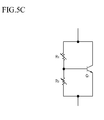
- variable resistors may be used for the resistors R1 and R2 as shown in FIG. 5A, 5B, and 5C. That is, a variable resistor may be used for the resistor R1 and/or the resistor R2.
- variable resistors When variable resistors are used for the resistors R1 and R2, the value of ⁇ V may be changed by adjusting the variable resistors after design. Accordingly, the low discharge may be further improved.
- a resistor that varies according to temperature may be used for the resistors R1 and R2. That is, the resistors R1 and R2 may be set to have a positive temperature coefficient (PTC) (i.e., a characteristic of increasing resistance as the temperature increases), or they may be set to have a negative temperature coefficient (NTC) (i.e., a characteristic of decreasing resistance as the temperature increases).
- PTC positive temperature coefficient
- NTC negative temperature coefficient
- the wall charges in the discharge cell are not actively changed, and the low address discharge deteriorates.
- the value of ⁇ V may be further increased by Equation 2 when the temperature is decreased. Accordingly, the problem in the low address discharge at the low temperature may be solved.
- a temperature coefficient of resistor R1 may be set to be negative. Additionally or alternatively, a temperature coefficient of resistor R2 may be set to be positive. In other cases, the problem caused by the temperature may be solved by appropriately setting the resistors R1 and R2 that vary according to temperature.
- the transistor Q1 is a bipolar transistor according to the first exemplary embodiment of the present invention, but the present invention is not limited thereto.
- a metal-oxide semiconductor field effect transistor (MOSFET) or an insulated gate bipolar transistor (IGBT) may be used, which will now be described.
- FIG. 6 illustrates a schematic diagram of a ⁇ V voltage generator 420b according to a second exemplary embodiment of the present invention.
- the ⁇ V voltage generator 420b according to the second exemplary embodiment of the present invention is the same as that of the first exemplary embodiment of the present invention, except that bipolar transistor Q1 is replaced with a MOSFET transistor M1, and therefore, descriptions of parts having been described will be omitted.
- the ⁇ V voltage generator 420b uses the transistor M1
- the ⁇ V voltage which is a drain-source voltage V DS of the transistor M1 is given as Equation 3.
- V DS 1 + R ⁇ 1 / R ⁇ 2 * V GS
- V GS is a gate-source voltage of the transistor M1.
- the base-emitter voltage V BE of the transistor Q1 in Equation 2 may be replaced with a gate-source voltage V GS of the transistor M1.
- the value of ⁇ V may be determined by the gate-source voltage (V GS ) of the transistor M1 and the values of the resistors R1 and R2 as shown in Equation 3.
- the resistors R1 and R2 may be variable resistors or may be resistors that vary according to temperature, as described above.
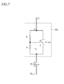
- FIG. 7 illustrates a diagram representing a ⁇ V voltage generator 420c according to a third exemplary embodiment of the present invention.
- the ⁇ V voltage generator 420c according to the third exemplary embodiment of the present invention is the same as that of the exemplary embodiment of the present invention, except that the bipolar transistor Q1 is replaced with an IGBT transistor Z1, and therefore, descriptions of parts having been described will be omitted.
- the ⁇ V voltage generator 420c uses the IGBT transistor Z1
- the ⁇ V voltage which is a collector-emitter voltage V CE of the transistor Z1
- V CE 1 + R ⁇ 1 / R ⁇ 2 * V GE
- V GE is a gate-emitter voltage of the transistor Z1.
- the base-emitter voltage V BE of the bipolar transistor Q1 in Equation 2 may be replaced with the a gate-emitter voltage V GE of the transistor Z1.
- the value of ⁇ V may be determined by the gate-emitter voltage V GE of the transistor Z1 and the values of the resistors R1 and R2.
- the resistors R1 and R2 may be variable or may be resistors that vary according to temperature, as described above.
- the Vnf voltage may be generated by using a single power source VscL. That is, the Vnf voltage and the VscL voltage having different levels may be supplied using the ⁇ V voltage generator 420a, 420b, and 420c according to the first to third exemplary embodiments of the present invention and the single power source VscL.
- the base-emitter voltage V BE of the transistor Q1, the gate-source voltage V GS of the transistor M1, and the gate-emitter voltage V GE of the transistor Z1 may exhibit NTC characteristics. That is, values of V BE , V GS and V CE may decrease as temperature increases. Referring to Equations 2, 3, and 4, the value of ⁇ V may decrease as temperature increases. At a high temperature, since the wall charges are actively moved in the discharge cell, the value of ⁇ V may need to be low to prevent low discharge. Accordingly, since the value of ⁇ V is reduced when the ⁇ V voltage generators according to the first to third exemplary embodiments of the present invention are used at increased temperatures, low discharge may be further improved at a high temperature. In addition, since the values of V BE , V GS , and V CE may further increase as the temperature decreases, the value of ⁇ V may further increase. Therefore, low discharge caused by low temperature may be prevented.
- a scan voltage and a final voltage of a reset period may be generated using one single power source.
- a value of ⁇ V may be variously realized by simply changing the resistors R1 and R2. These resistors may be variable or may change with temperature. Further, low address discharge may be efficiently prevented.
Landscapes
- Engineering & Computer Science (AREA)
- Physics & Mathematics (AREA)
- Power Engineering (AREA)
- Plasma & Fusion (AREA)
- Computer Hardware Design (AREA)
- General Physics & Mathematics (AREA)
- Theoretical Computer Science (AREA)
- Control Of Indicators Other Than Cathode Ray Tubes (AREA)
- Control Of Gas Discharge Display Tubes (AREA)
Applications Claiming Priority (1)
| Application Number | Priority Date | Filing Date | Title |
|---|---|---|---|
| KR1020060087367A KR100830977B1 (ko) | 2006-09-11 | 2006-09-11 | 플라즈마 표시 장치 및 그 전압 발생기 |
Publications (1)
| Publication Number | Publication Date |
|---|---|
| EP1898390A1 true EP1898390A1 (de) | 2008-03-12 |
Family
ID=38668764
Family Applications (1)
| Application Number | Title | Priority Date | Filing Date |
|---|---|---|---|
| EP07115874A Withdrawn EP1898390A1 (de) | 2006-09-11 | 2007-09-07 | Plasmaanzeige und Spannungsgenerator dafür |
Country Status (6)
| Country | Link |
|---|---|
| US (1) | US20080062076A1 (de) |
| EP (1) | EP1898390A1 (de) |
| JP (1) | JP2008070856A (de) |
| KR (1) | KR100830977B1 (de) |
| CN (1) | CN100583206C (de) |
| TW (1) | TW200818094A (de) |
Cited By (1)
| Publication number | Priority date | Publication date | Assignee | Title |
|---|---|---|---|---|
| EP1988532A1 (de) | 2007-05-03 | 2008-11-05 | Samsung SDI Co., Ltd. | Plasmaanzeige und Verfahren zu ihrer Ansteuerung |
Families Citing this family (2)
| Publication number | Priority date | Publication date | Assignee | Title |
|---|---|---|---|---|
| KR100879287B1 (ko) | 2007-08-02 | 2009-01-16 | 삼성에스디아이 주식회사 | 플라즈마 표시 장치 및 그 전압 생성기 |
| CN101930248B (zh) * | 2009-06-25 | 2013-06-12 | 上海华虹Nec电子有限公司 | 可调负电压基准电路 |
Citations (6)
| Publication number | Priority date | Publication date | Assignee | Title |
|---|---|---|---|---|
| US5745086A (en) | 1995-11-29 | 1998-04-28 | Plasmaco Inc. | Plasma panel exhibiting enhanced contrast |
| EP0846858A1 (de) * | 1996-12-09 | 1998-06-10 | Delco Electronics Corporation | Zündsteuerungssystem für Kraftfahrzeuge |
| US6040827A (en) | 1996-07-11 | 2000-03-21 | Hitachi, Ltd. | Driver circuit, driver integrated circuit, and display device and electronic device using the driver circuit and driver integrated circuit |
| EP1271462A2 (de) | 2001-06-29 | 2003-01-02 | Fujitsu Limited | Verfahren und Einrichtung zum Steuern einer Wechselstrom -Plasmaanzeigetafel |
| EP1564404A1 (de) * | 2004-02-17 | 2005-08-17 | Delphi Technologies, Inc. | Zündsystem für Kraftfahrzeuge mit funkloser sanfter Abschaltung als Thermisch-Überbelastungschutz |
| EP1750245A2 (de) | 2005-08-02 | 2007-02-07 | Samsung SDI Co., Ltd. | Plasmaanzeigetafel und Ansteuerschaltung für eine Plasmaanzeigetafel und Verfahren zur Ansteuerung einer Plasmaanzeigetafel |
Family Cites Families (16)
| Publication number | Priority date | Publication date | Assignee | Title |
|---|---|---|---|---|
| US5325107A (en) * | 1988-11-30 | 1994-06-28 | Sharp Kabushiki Kaisha | Method and apparatus for driving a display device |
| JPH0675650A (ja) * | 1992-04-27 | 1994-03-18 | Nec Corp | 基準電圧発生回路 |
| JPH07134558A (ja) * | 1993-11-08 | 1995-05-23 | Idemitsu Kosan Co Ltd | 有機エレクトロルミネッセンス表示装置 |
| JPH07146727A (ja) * | 1993-11-24 | 1995-06-06 | Nec Corp | 低電圧基準電圧発生回路 |
| US6144374A (en) * | 1997-05-15 | 2000-11-07 | Orion Electric Co., Ltd. | Apparatus for driving a flat panel display |
| JPH1117460A (ja) * | 1997-06-20 | 1999-01-22 | Denso Corp | 過熱保護機能付きトランジスタを備えた制御装置 |
| JP3449898B2 (ja) * | 1997-10-16 | 2003-09-22 | 富士通株式会社 | 発光素子駆動回路 |
| JP3465673B2 (ja) * | 2000-09-06 | 2003-11-10 | 株式会社村田製作所 | スイッチング電源装置 |
| US6679175B2 (en) * | 2001-07-19 | 2004-01-20 | Rocktek Limited | Cartridge and method for small charge breaking |
| KR100450189B1 (ko) * | 2001-10-15 | 2004-09-24 | 삼성에스디아이 주식회사 | 플라즈마 디스플레이 패널의 구동 회로 |
| KR100448477B1 (ko) | 2001-10-19 | 2004-09-13 | 엘지전자 주식회사 | 플라즈마 디스플레이 패널의 구동방법 및 장치 |
| KR100502895B1 (ko) * | 2003-03-18 | 2005-07-20 | 삼성에스디아이 주식회사 | 플라즈마 디스플레이 패널의 구동 회로 |
| JP2005128089A (ja) * | 2003-10-21 | 2005-05-19 | Tohoku Pioneer Corp | 発光表示装置 |
| KR100551033B1 (ko) * | 2004-04-12 | 2006-02-13 | 삼성에스디아이 주식회사 | 플라즈마 디스플레이 패널의 구동 방법, 플라즈마디스플레이 패널의 구동 장치 및 플라즈마 표시 장치 |
| KR100551008B1 (ko) * | 2004-05-20 | 2006-02-13 | 삼성에스디아이 주식회사 | 플라즈마 디스플레이 패널과 그의 구동 방법 |
| KR100823512B1 (ko) * | 2006-09-11 | 2008-04-21 | 삼성에스디아이 주식회사 | 플라즈마 표시 장치 및 그 전압 발생기 |
-
2006
- 2006-09-11 KR KR1020060087367A patent/KR100830977B1/ko not_active IP Right Cessation
-
2007
- 2007-04-13 JP JP2007106337A patent/JP2008070856A/ja active Pending
- 2007-06-29 US US11/819,848 patent/US20080062076A1/en not_active Abandoned
- 2007-07-02 TW TW096123988A patent/TW200818094A/zh unknown
- 2007-08-03 CN CN200710138287A patent/CN100583206C/zh not_active Expired - Fee Related
- 2007-09-07 EP EP07115874A patent/EP1898390A1/de not_active Withdrawn
Patent Citations (6)
| Publication number | Priority date | Publication date | Assignee | Title |
|---|---|---|---|---|
| US5745086A (en) | 1995-11-29 | 1998-04-28 | Plasmaco Inc. | Plasma panel exhibiting enhanced contrast |
| US6040827A (en) | 1996-07-11 | 2000-03-21 | Hitachi, Ltd. | Driver circuit, driver integrated circuit, and display device and electronic device using the driver circuit and driver integrated circuit |
| EP0846858A1 (de) * | 1996-12-09 | 1998-06-10 | Delco Electronics Corporation | Zündsteuerungssystem für Kraftfahrzeuge |
| EP1271462A2 (de) | 2001-06-29 | 2003-01-02 | Fujitsu Limited | Verfahren und Einrichtung zum Steuern einer Wechselstrom -Plasmaanzeigetafel |
| EP1564404A1 (de) * | 2004-02-17 | 2005-08-17 | Delphi Technologies, Inc. | Zündsystem für Kraftfahrzeuge mit funkloser sanfter Abschaltung als Thermisch-Überbelastungschutz |
| EP1750245A2 (de) | 2005-08-02 | 2007-02-07 | Samsung SDI Co., Ltd. | Plasmaanzeigetafel und Ansteuerschaltung für eine Plasmaanzeigetafel und Verfahren zur Ansteuerung einer Plasmaanzeigetafel |
Non-Patent Citations (1)
| Title |
|---|
| "Applying the superpower PA03 / Application note 6 / Power operational Amplifier", APEX MICROTECHNOLOGY APPLICATION NOTES, 28 February 1998 (1998-02-28), pages 1 - 6, XP007910451 * |
Cited By (1)
| Publication number | Priority date | Publication date | Assignee | Title |
|---|---|---|---|---|
| EP1988532A1 (de) | 2007-05-03 | 2008-11-05 | Samsung SDI Co., Ltd. | Plasmaanzeige und Verfahren zu ihrer Ansteuerung |
Also Published As
| Publication number | Publication date |
|---|---|
| TW200818094A (en) | 2008-04-16 |
| JP2008070856A (ja) | 2008-03-27 |
| CN100583206C (zh) | 2010-01-20 |
| KR100830977B1 (ko) | 2008-05-20 |
| KR20080023454A (ko) | 2008-03-14 |
| CN101145309A (zh) | 2008-03-19 |
| US20080062076A1 (en) | 2008-03-13 |
Similar Documents
| Publication | Publication Date | Title |
|---|---|---|
| US7733304B2 (en) | Plasma display and plasma display driver and method of driving plasma display | |
| US7542020B2 (en) | Power supply device and plasma display device including power supply device | |
| EP1898390A1 (de) | Plasmaanzeige und Spannungsgenerator dafür | |
| US20070085848A1 (en) | Plasma display device and a power supply thereof | |
| EP1898391A1 (de) | Plasmaanzeige und Spannungsgenerator dafür | |
| US8093818B2 (en) | Plasma display and voltage generator thereof | |
| KR100831015B1 (ko) | 플라즈마 표시 장치 및 그 구동 방법 | |
| EP2045794B1 (de) | Plasmaanzeige und Verfahren zu ihrer Ansteuerung | |
| US20090174627A1 (en) | Plasma display and driving device and method thereof | |
| US7830338B2 (en) | Plasma display and driving method thereof | |
| KR100823481B1 (ko) | 플라즈마 표시 장치 및 그 전압 생성기 | |
| US8125477B2 (en) | Plasma display and driving method thereof | |
| KR100879288B1 (ko) | 플라즈마 표시 장치 및 그 구동 방법 | |
| KR100869809B1 (ko) | 플라즈마 표시 장치 | |
| US20080136807A1 (en) | Plasma display device and driving method thereof | |
| US20130120345A1 (en) | Plasma display and driving method thereof | |
| EP1944745A2 (de) | Plasmaanzeige und Treiber dafür | |
| US8570247B2 (en) | Plasma display device, and apparatus and method for driving the same | |
| KR100823493B1 (ko) | 플라즈마 표시 장치 및 그 구동 방법 | |
| EP1840865A1 (de) | Plasmaanzeige sowie Vorrichtung und Verfahren zu ihrer Ansteuerung |
Legal Events
| Date | Code | Title | Description |
|---|---|---|---|
| PUAI | Public reference made under article 153(3) epc to a published international application that has entered the european phase |
Free format text: ORIGINAL CODE: 0009012 |
|
| 17P | Request for examination filed |
Effective date: 20070907 |
|
| AK | Designated contracting states |
Kind code of ref document: A1 Designated state(s): AT BE BG CH CY CZ DE DK EE ES FI FR GB GR HU IE IS IT LI LT LU LV MC MT NL PL PT RO SE SI SK TR |
|
| AX | Request for extension of the european patent |
Extension state: AL BA HR MK YU |
|
| RIN1 | Information on inventor provided before grant (corrected) |
Inventor name: JEON, YOUNG-JUN Inventor name: KIM, SUK-KI Inventor name: PARK, JUNG-PIL Inventor name: KIM, JEONG-HOON |
|
| AKX | Designation fees paid |
Designated state(s): AT BE BG CH CY CZ DE DK EE ES FI FR GB GR HU IE IS IT LI LT LU LV MC MT NL PL PT RO SE SI SK TR |
|
| 17Q | First examination report despatched |
Effective date: 20091117 |
|
| STAA | Information on the status of an ep patent application or granted ep patent |
Free format text: STATUS: THE APPLICATION IS DEEMED TO BE WITHDRAWN |
|
| 18D | Application deemed to be withdrawn |
Effective date: 20140401 |