EP1898231A1 - Radargerät - Google Patents
Radargerät Download PDFInfo
- Publication number
- EP1898231A1 EP1898231A1 EP07016312A EP07016312A EP1898231A1 EP 1898231 A1 EP1898231 A1 EP 1898231A1 EP 07016312 A EP07016312 A EP 07016312A EP 07016312 A EP07016312 A EP 07016312A EP 1898231 A1 EP1898231 A1 EP 1898231A1
- Authority
- EP
- European Patent Office
- Prior art keywords
- housing
- control circuit
- radar device
- antenna module
- circuit board
- Prior art date
- Legal status (The legal status is an assumption and is not a legal conclusion. Google has not performed a legal analysis and makes no representation as to the accuracy of the status listed.)
- Withdrawn
Links
Images


Classifications
-
- G—PHYSICS
- G01—MEASURING; TESTING
- G01S—RADIO DIRECTION-FINDING; RADIO NAVIGATION; DETERMINING DISTANCE OR VELOCITY BY USE OF RADIO WAVES; LOCATING OR PRESENCE-DETECTING BY USE OF THE REFLECTION OR RERADIATION OF RADIO WAVES; ANALOGOUS ARRANGEMENTS USING OTHER WAVES
- G01S7/00—Details of systems according to groups G01S13/00, G01S15/00, G01S17/00
- G01S7/02—Details of systems according to groups G01S13/00, G01S15/00, G01S17/00 of systems according to group G01S13/00
- G01S7/03—Details of HF subsystems specially adapted therefor, e.g. common to transmitter and receiver
- G01S7/032—Constructional details for solid-state radar subsystems
-
- H—ELECTRICITY
- H05—ELECTRIC TECHNIQUES NOT OTHERWISE PROVIDED FOR
- H05K—PRINTED CIRCUITS; CASINGS OR CONSTRUCTIONAL DETAILS OF ELECTRIC APPARATUS; MANUFACTURE OF ASSEMBLAGES OF ELECTRICAL COMPONENTS
- H05K7/00—Constructional details common to different types of electric apparatus
- H05K7/20—Modifications to facilitate cooling, ventilating, or heating
- H05K7/2039—Modifications to facilitate cooling, ventilating, or heating characterised by the heat transfer by conduction from the heat generating element to a dissipating body
- H05K7/20436—Inner thermal coupling elements in heat dissipating housings, e.g. protrusions or depressions integrally formed in the housing
-
- H—ELECTRICITY
- H05—ELECTRIC TECHNIQUES NOT OTHERWISE PROVIDED FOR
- H05K—PRINTED CIRCUITS; CASINGS OR CONSTRUCTIONAL DETAILS OF ELECTRIC APPARATUS; MANUFACTURE OF ASSEMBLAGES OF ELECTRICAL COMPONENTS
- H05K7/00—Constructional details common to different types of electric apparatus
- H05K7/20—Modifications to facilitate cooling, ventilating, or heating
- H05K7/20845—Modifications to facilitate cooling, ventilating, or heating for automotive electronic casings
- H05K7/20854—Heat transfer by conduction from internal heat source to heat radiating structure
-
- G—PHYSICS
- G01—MEASURING; TESTING
- G01S—RADIO DIRECTION-FINDING; RADIO NAVIGATION; DETERMINING DISTANCE OR VELOCITY BY USE OF RADIO WAVES; LOCATING OR PRESENCE-DETECTING BY USE OF THE REFLECTION OR RERADIATION OF RADIO WAVES; ANALOGOUS ARRANGEMENTS USING OTHER WAVES
- G01S13/00—Systems using the reflection or reradiation of radio waves, e.g. radar systems; Analogous systems using reflection or reradiation of waves whose nature or wavelength is irrelevant or unspecified
- G01S13/88—Radar or analogous systems specially adapted for specific applications
- G01S13/93—Radar or analogous systems specially adapted for specific applications for anti-collision purposes
- G01S13/931—Radar or analogous systems specially adapted for specific applications for anti-collision purposes of land vehicles
-
- G—PHYSICS
- G01—MEASURING; TESTING
- G01S—RADIO DIRECTION-FINDING; RADIO NAVIGATION; DETERMINING DISTANCE OR VELOCITY BY USE OF RADIO WAVES; LOCATING OR PRESENCE-DETECTING BY USE OF THE REFLECTION OR RERADIATION OF RADIO WAVES; ANALOGOUS ARRANGEMENTS USING OTHER WAVES
- G01S7/00—Details of systems according to groups G01S13/00, G01S15/00, G01S17/00
- G01S7/02—Details of systems according to groups G01S13/00, G01S15/00, G01S17/00 of systems according to group G01S13/00
- G01S7/027—Constructional details of housings, e.g. form, type, material or ruggedness
Definitions
- the present invention relates to a radar device which is mounted on a motor vehicle and is used for a safety control of the motor vehicle such as to detect an object in back and forth and right and left directions of the motor vehicle or the like.
- the radar device shown in JP-A-10-261917 is structured such that an antenna, a high-frequency circuit portion and a control circuit portion are piled up in this order so as to be accommodated in an inner portion of a casing, and are fixed to the casing by screws or the like, a ground potential metal layer is provided between the high-frequency circuit portion and the control circuit portion, and a through hole is formed in the ground potential metal layer, and is connected by a core wire coated by a glass layer, thereby forming an electric connection between the control circuit portion existing on a back surface of the ground potential metal layer and the high-frequency circuit portion existing on a front surface.
- the radar device shown in JP-A-2001-324561 is structured such that a control circuit mounting electronic parts thereon is installed in a casing made of a metal such as an aluminum die casting or the like, an antenna module mounting a transmitting antenna and a receiving antenna on an antenna base made of a metal is arranged in an opening portion of the casing, and the antenna module is covered by a radome, whereby the control circuit mounting the electronic parts thereon and the antenna module are surrounded by the housing constituted by the casing and the radome.
- the connector achieving the electric connection to an external device is structured such as to be mounted to the housing via an O-ring by a screw, and a GND which is common in the control circuit and the antenna module is electrically connected to the base and the housing, and is connected to a vehicle body GND only via a capacitive impedance.
- the antenna module is arranged within the housing constituted by the casing and the radome, and any special consideration for a heat generated in the antenna module is not taken. Accordingly, if it is intended to downsize the radar device, a contact area with an ambient air becomes small, and the heat generated from the antenna module is not sufficiently discharged to an external portion, so that the antenna module comes to a high temperature, a characteristic of the electric wave is changed, and there is a case that a send and receive is stopped at the worst.
- the electric connection between the control circuit portion existing on the back surface of the ground potential metal layer and the high-frequency circuit portion existing on the front surface is formed by forming the through hole in the ground potential metal layer, and connecting by the core wire coated by the glass layer, and the connector is attached to the housing by the O-ring and the screw, it is complicated to attach the connector to the housing, connect between the control circuit boards and connect the control circuit board and the antenna module, and it is impossible to achieve a compact and light structure and a cost increase is caused as well as it is hard to automate an assembly.
- the present invention aims at improving the points mentioned above, and an object of the present invention is to provide a radar device in which a radar device is easily assembled by making a housing of the radar device of a resin, making a front cover and a rear cover of metal, and firmly attaching an antenna module to the metal front cover, and it is possible to achieve downsizing and cost reduction.
- a radar device in accordance with the present invention is basically provided with a resin housing having opening portions on upper and lower sides, a control circuit board mounted within the housing, a metal front cover attached to the housing so as to close the upper opening portion of the housing, and/or a metal rear cover attached to the housing so as to close the lower opening portion of the housing, and/or the antenna module is attached to the front cover.
- a radar device in accordance with the present invention is provided with a resin housing having opening portions on upper and lower sides, a control circuit board provided with a control circuit and mounted within the housing, a metal front cover attached to the housing so as to close the upper opening portion of the housing, and/or a metal rear cover attached to the housing so as to close the lower opening portion of the housing, an opening portion is provided in the front cover, a peripheral edge of the antenna module is firmly attached to an opening edge of the opening portion, and/or the opening portion is coated by a radome having a good electric wave permeability.
- the peripheral edge of the antenna module is firmly attached to the opening edge of the opening portion of the metal front cover, heat generated by the antenna module is conducted to the metal front cover from the peripheral edge thereof, and the heat conducted to the front cover is discharged to an ambient air from the portion of the front cover which is in contact with the ambient air. Accordingly, even if the radar device is downsized, the antenna module is efficiently cooled and does not come to a high temperature. Therefore, it is possible to stably transmit and receive the electric wave. Further, since the rear cover covering the outer side of the control circuit board is made of metal, the heat generated from the control circuit board is discharged from the rear cover.
- the housing, the control circuit board and the rear cover can be assembled in order from one side to the front cover in which the antenna module and the radome are fixed to the opening portion, it is possible to easily assemble the radar device, and the present invention is suitable for automatically assembling the radar device.
- a connector portion is integrally formed with the resin housing in the radar device, and a relay terminal relaying the antenna module and the control circuit board, and a connector terminal are provided in accordance with an insert mold forming.
- a radar device in accordance with the present invention comprises a housing having opening portions on upper and lower sides and made of resin and metal, a circuit control board provided with a control circuit and mounted within the housing, a metal front cover attached to the housing so as to close the upper opening portion of the housing, and/or a metal rear cover attached to the housing so as to close the lower opening portion of the housing, the housing is structured by resin in a portion in which a relay terminal relaying the antenna module and the control circuit board is arranged, and a portion in which the connector portion is provided, the connector portion is integrally formed with the housing, the relay terminal and the connector terminal are provided in accordance with an insert mold forming, an opening portion is provided in the front cover, a peripheral edge of the antenna module is firmly attached to an opening edge of the opening portion, and the opening portion is coated by a radome having a good electric wave permeability.
- the peripheral edge of the antenna module is firmly attached to the opening edge of the opening portion of the metal front cover, heat generated by the antenna module is conducted to the metal front cover from the peripheral edge thereof, and the heat conducted to the front cover is discharged to an ambient air from the portion of the front cover which is in contact with the ambient air. Accordingly, even if the radar device is downsized, the antenna module is efficiently cooled and does not come to a high temperature. Therefore, it is possible to stably transmit and receive the electric wave. Further, since the rear cover covering the outside of the control circuit board is made of metal, and many of the portions of the housing are made of metal, the heat generated from the elements of the control circuit board is discharged from the rear cover and the housing.
- the present invention is suitable for automatically assembling the radar device. Further, since the present invention is structured by resin in the portion in which the relay terminal relaying the antenna module and the control circuit board is arranged, and the portion in which the connector portion is provided, the connector portion can be simply provided by being integrally formed with the housing, and the relay terminal and the connector terminal can be provided in the housing in an insulating state without any trouble in accordance with an insert mold forming.
- the front cover and the rear cover in the radar device are attached to the housing by engaging the screws from the rear cover with the front cover.
- connection portion of the antenna module and the connection portion of the relay terminal are arranged close to each other, and are connected in accordance with wire bonding, soldering of a lead wire or the like.
- connection portion of the control circuit board and the connection portion of the connector terminal are arranged close to each other, the connection portion of the control circuit board and the connection portion of the relay terminal are arranged close to each other, and they are respectively connected in accordance with wire bonding, soldering of a lead wire or the like.
- the metal rear cover in the radar device is provided with a convex block at least on an inner surface.
- the present invention since it is possible to efficiently cool the antenna module, it is possible to downsize the radar device, and it is possible to assemble the housing, the control circuit board and the rear cover in order from one side to the front cover in which the antenna module and the radome are fixed to the opening portion. Accordingly, it is possible to efficiently automate and execute the assembling work of the radar device, and it is possible to achieve cost reduction.
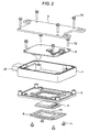
- Fig. 1 is an assembled perspective view of the radar apparatus in accordance with the present embodiment
- Fig. 2 is an exploded perspective view of the radar apparatus in accordance with the present embodiment
- Fig. 3 is a cross sectional view of the radar apparatus in accordance with the present embodiment.
- the radar device is constituted by a housing 1, a front cover 2, a rear cover 3, an antenna module 4 transmitting and receiving an electric wave, a control circuit board 5, and a radome 6.
- the antenna module 4 has a known structure, emits the electric wave and receives a reflected electric wave.
- the radome 6 is structured by a material having a good electric wave permeability, and a narrow convex groove 61 is formed in an outer periphery.
- Fig. 4 is a plan view showing details of a first embodiment of the housing 1.
- the housing 1 is formed in a rectangular shape by synthetic resin, opening portions are formed on upper and lower sides of the housing 1, and the housing 1 is constructed by front, rear, left and right side walls 11a, 11b, 11c and 11d.
- a hole 17 for inserting a screw 73 is formed in each of four corners of the side walls 11a, 11b, 11c and 11d of the housing 1, and a metal sleeve 18 is inserted to the hole 17.
- first step portion 11f which is lower than an upper surface of the side wall
- second stage portion 11g which is further lower.
- the second stage portion 11g is provided for mounting the control circuit board 5 thereon, and a hole 19 to which a screw 72 for attaching the control circuit board 5 is inserted is formed in each of four corners of the second stage portion 11g.
- a narrow protruding portion 12 is formed in a portion close to a front cover in the wall 11d on the right side, and a connector portion 13 is integrally formed with the housing in the side wall 11c on the left side.
- a relay terminal 14 is provided in the side wall 11d on the right side of the housing 1 in accordance with insert mold forming, an intermediate portion 14a of the relay terminal 14 is inserted into the housing 1, one end portion 14b is arranged in the first stage portion 11f so as to form a connection portion to the control circuit board 5, and the other end portion 14c is arranged in the protruding portion 12 so as to form a connection portion to the antenna module 4.
- a connector terminal 15 is provided in the side wall 11c on the left side of the housing 1 in accordance with the insert mold forming, an intermediate portion 15a of the connector terminal 15 is inserted into the housing 1, one end portion 15b is protruded into the connector portion 13, and the other end portion 15c is arranged in the first stage portion 11f so as to form a connection portion to the control circuit board 5.
- a narrow groove 16a is formed in a full circle, and holes (not shown) to which a first column body 22 and a second column body 23 of the front cover 2 are inserted are formed, and a narrow groove 16b is formed in a full circle on lower surfaces thereof.
- the housing is formed by resin
- the connector portion 13 can be provided simply by being integrally formed with the housing 1
- the relay terminal 14 and the connector terminal 15 can be provided in an insulated state in the housing 1 without any trouble in accordance with an insert mold forming. Further, since the connector portion 13, the relay terminal 14 and the connector terminal 15 are integrally formed with the housing 1, the number of the parts assembling the radar device is reduced.
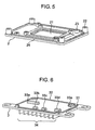
- Fig. 5 is a perspective view showing details of the front cover 2.
- the front cover 2 is attached so as to close the opening portion in the upper side of the housing 1, and is structured in a rectangular shape by metal such as aluminum or the like, and an opening portion 21 is formed in a center thereof.
- the first column body 22 having a female thread formed thereon is formed at each of four corners of the front cover 2, and the second column body 23 having a female thread formed thereon is formed at each of the four corners on an inner side thereof.
- a narrow convex groove 24 is formed around the front cover 2, is fitted into the groove 16a of the housing 1, and seals so as to prevent rain water or the like from making an intrusion into the housing 1.
- a narrow groove 25 (Fig. 3) is formed around the opening portion 21 in an outer surface of the front cover 2.
- Fig. 6 is a perspective view showing details of the rear cover 3.
- the rear cover 3 is attached so as to close the opening portion in the lower portion of the housing 1, and is formed in a rectangular shape by metal such as aluminum or the like, and a hole 31 is formed at each of four corners thereof.
- a convex ridge 32 is formed around the inner surface of the rear cover 3, is fitted into a groove 16b formed in the housing 1, and seals so as to prevent rain water or the like from making an intrusion into the housing 1.
- convex blocks such as a heat radiation fin 34 or the like are formed on an outer surface, and heat generated by the control circuit board 5 is absorbed by the thermally conductive blocks 33 (convex blocks on the inner surface) and is discharged to the outside by the heat radiation fins 34 (the convex blocks on the outer surface).
- Fig. 7 shows details of the control circuit board 5, and is a plan view showing a state in which the control circuit board 5 is attached to the housing 1.
- the control circuit board 5 is provided with a power supply circuit portion 51 and a high-frequency circuit portion 52, the power supply circuit portion 51 is arranged so as to be collected close to the connector portion 13 of the housing 1, and the high-frequency circuit portion 52 is arranged at a position which is away from the power supply circuit portion 51. This is for preventing the matter that a sensitivity of detection is deteriorated by a superimposition of noise generated from the power supply circuit portion 51 on the high-frequency circuit portion 52, and thereby, the erroneous detection is caused.
- a mounting hole 53 for attaching the control circuit board 5 is formed at each of four corners of the control circuit board 5.
- the radar device in accordance with the present invention is structured such that the antenna module 4 and the radome 6 are first installed in the metal front cover 2, and the other members can be assembled in order from one side.
- the radar device is assembled by arranging the antenna module 4 in the opening portion 21 of the metal front cover 2 from the outside, firmly attaching the peripheral edge of the antenna module 4 to the peripheral edge of the opening portion 21 by brazing material such as solder or the like or adhesive agent, further fitting a convex ridge 61 of the radome 6 for protecting the antenna in a groove 25 formed around the opening portion 21 so as to be firmly attached by adhesive agent, so as to cover the opening portion 21.
- the attachment of the radome 6 is reinforced by a screw 71
- the screw 71 is formed by synthetic resin so as to be prevented from forming an obstacle to the transmission and receiving of the electric wave.
- connection portion of the antenna module 4 is arranged close to the connection portion (the other end portion 14c) of the relay terminal 14 provided in the housing 1, the connection portion of the antenna module 4 is connected to the connection portion of the relay terminal 14 by a wire lead 81 in accordance with a wire bonding connection. It is not necessary to use a harness or the like for connecting the connection portion of the antenna module 4 and the connection portion of the relay terminal 14, it is possible to automatically connect the relay terminal 14 and the antenna module 4, and it is possible to achieve cost reduction.
- control circuit board 5 is mounted to the second stage portion 11g of the housing 1, the screws 72 are inserted to the holes 53 formed at four corners of the control circuit board 5 and the holes 19 of the housing 1, and the screws 72 are engaged with the female threads of the second column bodies 23 of the front cover 2 so as to fix the control circuit board 5.
- connection portion of the control circuit board 5 and the connection portion (one end portion 14b) of the relay terminal 14 are arranged close to each other, and the connection portion of the control circuit board 5 and the connection portion (the other end portion 15c) of the connector terminal 15 are arranged close to each other, these portions are connected by the wire leads 82 and 83 in accordance with wire bonding connection. Since it is possible to connect without using any wire harness, and it is possible to automatically connect them, it is possible to reduce cost.
- the radar device is assembled finally by applying the adhesive agent to the groove 16b or the like of the housing 1, fitting the convex ridge 32 of the rear cover 3 to the groove 16b, inserting the screws 73 to the holes 31 of the rear cover 3 and the sleeves 18 of the housing 1, engaging with the female thread of the first column body 22 of the front cover 2 so as to couple the front cover 1 and the rear cover 3 by the screws 73, and fastening the front cover 1 and the rear cover 3 to the housing 1.
- the present embodiment since after constructing by assembling the housing 1, the control circuit board 5 and the rear cover 3 to the front cover 2 in order from one side, the screws 73 from the rear cover 3 are engaged with the metal front cover 2, it is possible to firmly attach the front cover 2 and the rear cover 3 to the housing 1, it is possible to assemble the radar device in order from one side, and it is possible to automatically construct it. Further, since a screw head is not arranged in the front cover 2 at which the antenna module 4 is positioned, the transmission and receiving of the electric wave is not obstructed in the antenna module 4.
- the constructed radar device is structured such that the thermally conductive blocks 33 (the convex blocks on the inner surface) of the rear cover 3 are arranged close to the heat generating portion of the control circuit board 5, the heat generated in the circuit board 5 is absorbed by the thermally conductive blocks 33 and is radiated to the outside from the heat radiating fins 34 (the convex blocks on the outer surface).
- the structure is made such that the thermally conductive block 33 comes into contact with the control circuit board 5 at a time of attaching the rear cover 3 to the housing 1, or the structure is made such that the thermally conductive block 33 and the control circuit board 5 are adhered by thermal conductive adhesive agent applied to the thermally conductive block 33 or a thermal conductive sheet adhered to the thermally conductive block 33 or the like, the heat of the control circuit board 5 is conducted to the thermally conductive block 33 via the adhesive agent or the sheet or the like, and it is possible to more effectively absorb the heat generated in the control circuit board 5 by the rear cover 3.
- the sleeve 18 inserted to the hole 17 of the housing 1 is made of metal, a slack is not generated in the screw 73 even if the resin constituting the housing is contracted, and the potential of the antenna module 4 flows to the rear cover by the metal sleeve 18 so as to be kept at a ground level.
- the radar device in accordance with the present embodiment can be constructed from one side in all the works including the attaching work between the front cover 2 and the housing 1, the wire bonding connecting work between the antenna module and the relay terminal, the attaching work of the control circuit board to the housing 1, the wire bonding connecting work among the control circuit board, the relay terminal and the connector terminal, the attaching work of the rear cover 3 to the housing 1, and the coupling work of the rear cover 3 to the housing 1 in accordance with the insertion of the screw 73, it is possible to efficiently execute the constructing work, it is possible to automatically construct and it is possible to achieve cost reduction.
- Fig. 8 is a plan view showing the other embodiment of the housing 1, and an explanatory view in the case that the housing 1 is structured by resin and metal.
- the housing is structured by synthetic resin in a portion A and a portion B in Fig. 8, a housing 1C formed by metal is formed narrow in the portion A and the portion B, and synthetic resin housings 1A and 1B are formed so as to wrap the metal housing 1C formed narrow.
- a connector portion 13A is integrally formed with the housing 1A formed by synthetic resin, and a connector terminal 15 is provided in accordance with the insert mold forming.
- the housing 1B formed by synthetic resin is provided with a relay terminal 14 relaying the antenna module 4 and the control circuit board 5 in accordance with the insert mold forming.
- the housing 1 in accordance with the embodiment can radiate the heat generated in the control circuit board 5 and the antenna module 4 by the metal portion, and the relay terminal 14 and the connector terminal 15 can be simply provided in the housing without applying any insulating treatment, by insert molding the relay terminal 14 and the connector terminal 15 in the housings 1B and 1C formed by synthetic resin.
- the antenna module 4 is arranged in the opening portion 21 of the front cover 2 from the outside, however, the antenna module 4 may be arranged in the opening portion 21 from the inside so as to fix the peripheral edge of the antenna module 4 to the peripheral edge of the opening portion 21, or the antenna module 4 and the radome 6 may be simultaneously fixed to the front cover 2 by the adhesive agent or the like in a state in which the antenna module 4 is previously fixed to the radome 6 by the adhesive agent or the like.
Landscapes
- Engineering & Computer Science (AREA)
- Physics & Mathematics (AREA)
- Thermal Sciences (AREA)
- Microelectronics & Electronic Packaging (AREA)
- Radar, Positioning & Navigation (AREA)
- Remote Sensing (AREA)
- Computer Networks & Wireless Communication (AREA)
- General Physics & Mathematics (AREA)
- Details Of Aerials (AREA)
- Radar Systems Or Details Thereof (AREA)
- Support Of Aerials (AREA)
Applications Claiming Priority (1)
| Application Number | Priority Date | Filing Date | Title |
|---|---|---|---|
| JP2006243303A JP4286855B2 (ja) | 2006-09-07 | 2006-09-07 | レーダ装置 |
Publications (1)
| Publication Number | Publication Date |
|---|---|
| EP1898231A1 true EP1898231A1 (de) | 2008-03-12 |
Family
ID=38626505
Family Applications (1)
| Application Number | Title | Priority Date | Filing Date |
|---|---|---|---|
| EP07016312A Withdrawn EP1898231A1 (de) | 2006-09-07 | 2007-08-20 | Radargerät |
Country Status (3)
| Country | Link |
|---|---|
| US (1) | US20080062038A1 (de) |
| EP (1) | EP1898231A1 (de) |
| JP (1) | JP4286855B2 (de) |
Cited By (10)
| Publication number | Priority date | Publication date | Assignee | Title |
|---|---|---|---|---|
| WO2010018934A3 (en) * | 2008-08-13 | 2010-07-08 | Electronics And Telecommunications Research Institute | System for controlling temperature of antenna module |
| CN103207384A (zh) * | 2012-01-17 | 2013-07-17 | 万都株式会社 | 雷达装置及其装配方法 |
| WO2015050994A1 (en) * | 2013-10-01 | 2015-04-09 | Autoliv Asp, Inc. | Compact shielded automotive radar module and method |
| EP3070784A1 (de) * | 2015-03-18 | 2016-09-21 | Toyota Jidosha Kabushiki Kaisha | Fahrzeugradarvorrichtung |
| CN106507625A (zh) * | 2016-11-22 | 2017-03-15 | 中瑞丸达机电科技(北京)有限公司 | 控制器及立体车库电控箱 |
| CN107148188A (zh) * | 2017-06-16 | 2017-09-08 | 广东欧珀移动通信有限公司 | 壳体组件的制备方法、壳体组件和移动终端 |
| EP3200278A4 (de) * | 2014-09-25 | 2018-06-13 | Nec Corporation | Antennensystem |
| US10074907B2 (en) | 2015-03-12 | 2018-09-11 | Veoneer Us, Inc. | Apparatus and method for mitigating multipath effects and improving absorption of an automotive radar module |
| CN110945375A (zh) * | 2017-07-31 | 2020-03-31 | 大金工业株式会社 | 传感器单元和空调机 |
| EP3737216A1 (de) * | 2015-09-18 | 2020-11-11 | Toray Industries, Inc. | Gehäuse einer elektronischen vorrichtung |
Families Citing this family (35)
| Publication number | Priority date | Publication date | Assignee | Title |
|---|---|---|---|---|
| DE102011052363A1 (de) * | 2011-08-02 | 2013-02-07 | Hella Kgaa Hueck & Co. | Radarsensor |
| TWM423936U (en) * | 2011-09-13 | 2012-03-01 | Tyco Electronics Holdings Bermuda No 7 Ltd | Smartcard connector with RFID module |
| JP5797601B2 (ja) * | 2012-04-27 | 2015-10-21 | オートリブ ディベロップメント エービー | 車載回路基板収容筐体 |
| US20140062799A1 (en) * | 2012-08-29 | 2014-03-06 | Motorola Mobility Llc | Wireless communication device and method with an enhanced antenna farm |
| JP5628964B1 (ja) * | 2013-05-02 | 2014-11-19 | 三菱電機株式会社 | レーダ装置 |
| CN103473994B (zh) * | 2013-09-16 | 2015-06-03 | 樊书印 | 一种电子相册 |
| DE102014105271A1 (de) * | 2014-04-14 | 2015-10-15 | Hella Kgaa Hueck & Co. | Radarsensor und Verfahren zur Herstellung eines Radarsensors |
| JP6498931B2 (ja) * | 2014-12-25 | 2019-04-10 | 株式会社Soken | レーダ装置、及びカバー部材 |
| USD836505S1 (en) * | 2015-08-31 | 2018-12-25 | Cummins Inc. | Compression relief brake assembly |
| USD828249S1 (en) * | 2015-08-31 | 2018-09-11 | Cummins Inc. | Compression relief brake assembly |
| USD828250S1 (en) * | 2015-08-31 | 2018-09-11 | Cummins Inc. | Compression relief brake system |
| USD813124S1 (en) * | 2015-08-31 | 2018-03-20 | Cummins Inc. | Rocker for compression relief brake |
| USD808872S1 (en) * | 2015-09-11 | 2018-01-30 | Eaton S.R.L. | Rocker arm for engine brake |
| DE102015223243A1 (de) * | 2015-11-24 | 2017-05-24 | Innosent Gmbh | Gehäuse für einen Radarsensor und ein solcher Radarsensor |
| CN110087851B (zh) * | 2016-12-22 | 2024-04-12 | 日立安斯泰莫株式会社 | 电子控制装置 |
| USD878259S1 (en) * | 2017-10-17 | 2020-03-17 | Pintsch Bubenzer Gmbh | Braking unit |
| USD955944S1 (en) | 2017-04-20 | 2022-06-28 | Dellner Bubenzer Germany Gmbh | Braking unit column |
| US11054514B2 (en) * | 2017-11-22 | 2021-07-06 | Magna Closures Inc. | Radar beam forming shield for motor vehicle |
| JP7084181B2 (ja) * | 2018-03-30 | 2022-06-14 | 古河電気工業株式会社 | レーダ装置 |
| JP7084182B2 (ja) * | 2018-03-30 | 2022-06-14 | 古河電気工業株式会社 | レーダ装置 |
| CN108663661B (zh) * | 2018-08-31 | 2023-10-20 | 成都天箭科技股份有限公司 | 一种新型相控阵雷达阵面锁紧结构及其锁紧方法 |
| US10694637B1 (en) * | 2018-09-20 | 2020-06-23 | Rockwell Collins, Inc. | Modular antenna array system with thermal management |
| KR102660413B1 (ko) * | 2018-10-08 | 2024-04-24 | 주식회사 에이치엘클레무브 | 레이더 장치 및 이를 포함하는 레이더 센싱 장치 |
| KR102242930B1 (ko) * | 2019-08-22 | 2021-04-21 | 주식회사 만도 | 레이더 장치 마운팅 어셈블리 |
| DE102020210454A1 (de) | 2019-08-27 | 2021-05-12 | Motional AD LLC (n.d.Ges.d. Staates Delaware) | Kühllösungen für autonome Fahrzeuge |
| DE102020121532A1 (de) | 2019-08-29 | 2021-03-04 | Motional AD LLC (n.d.Ges.d. Staates Delaware) | Sensorgehäuse |
| CN110412513A (zh) * | 2019-09-05 | 2019-11-05 | 全义 | 一种水下地质雷达防水装置 |
| US11044823B2 (en) * | 2019-11-22 | 2021-06-22 | Continental Automotive Systems, Inc. | Positioning pins for foldable printed circuit board |
| CN113138368A (zh) * | 2020-01-20 | 2021-07-20 | 华为技术有限公司 | 一种雷达装置和移动平台 |
| CN111522009A (zh) * | 2020-04-03 | 2020-08-11 | 宁波锐眼电子科技有限公司 | 雷达结构 |
| KR102346358B1 (ko) * | 2020-07-08 | 2022-01-03 | 세빈기술주식회사 | 물체 감지 장치 |
| DE112020007888T5 (de) * | 2020-12-28 | 2023-10-19 | Mitsubishi Electric Corporation | Fahrzeuginterne Radarvorrichtung |
| JP2022153009A (ja) | 2021-03-29 | 2022-10-12 | 京セラ株式会社 | 電子機器 |
| CN113267782B (zh) * | 2021-05-18 | 2023-10-03 | 沈阳工程学院 | 一种可自发电加热的声雷达防护装置及其控制方法 |
| JP7364807B1 (ja) * | 2023-01-23 | 2023-10-18 | 株式会社フジクラ | 無線モジュール |
Citations (14)
| Publication number | Priority date | Publication date | Assignee | Title |
|---|---|---|---|---|
| EP0642190A1 (de) * | 1993-09-07 | 1995-03-08 | Trw Inc. | Eingebaute Strahlerstruktur für einen Millimeterwellenradarsensor |
| US5451970A (en) * | 1992-05-28 | 1995-09-19 | Cole; Carroll R. | Radar antenna unit having a plurality of heat dissipating fins forming on the exterior of a cone shaped chamber |
| EP0971436A2 (de) * | 1998-07-06 | 2000-01-12 | Murata Manufacturing Co., Ltd. | Antennenanordnung und Sende-/Empfangsgerät |
| US6067232A (en) * | 1996-12-31 | 2000-05-23 | Intel Corporation | System for connecting subsystems of dissimilar thermal properties |
| US6094161A (en) * | 1998-09-23 | 2000-07-25 | Northrop Grumman Corporation | Dual channel microwave transmit/receive module for an active aperture of a radar system |
| WO2000045462A1 (de) * | 1999-01-28 | 2000-08-03 | Robert Bosch Gmbh | Gehäuse für ein elektronisches gerät in der mikrowellentechnik |
| EP1049192A2 (de) * | 1999-04-26 | 2000-11-02 | Hitachi, Ltd. | Hochfrequenz-Kommunikationsgerät |
| US20010040524A1 (en) * | 2000-05-15 | 2001-11-15 | Hitachi, Ltd. | Vehicle-mounted radio wave radar |
| US20030164461A1 (en) * | 2002-01-24 | 2003-09-04 | Kelly Thomas Hayes | Compact integrated infrared scene projector |
| US6654399B1 (en) * | 1999-02-24 | 2003-11-25 | Denso Corporation | Semiconductor light projection apparatus and distance measurement apparatus |
| EP1411583A1 (de) * | 2002-10-16 | 2004-04-21 | Hitachi, Ltd. | Radargerät |
| EP1462817A1 (de) * | 2003-03-24 | 2004-09-29 | Hitachi, Ltd. | Millimeterwellenradargerät und dessen Herstellungsverfahren |
| WO2005043675A1 (de) * | 2003-10-27 | 2005-05-12 | Robert Bosch Gmbh | Antennenanordnung insbesondere für radaranwendungen bei kraftfahrzeugen |
| EP1677126A1 (de) * | 2004-12-28 | 2006-07-05 | Hitachi, Ltd. | Doppler-Geschwindigkeit-Sensor mit fokussiertem Strahl |
Family Cites Families (16)
| Publication number | Priority date | Publication date | Assignee | Title |
|---|---|---|---|---|
| DE3030102A1 (de) * | 1980-08-08 | 1982-02-25 | Siemens AG, 1000 Berlin und 8000 München | Geraet mit gehaeuse fuer einen funksende-empfaenger der elektrischen nachrichtentechnik |
| US4517566A (en) * | 1982-09-07 | 1985-05-14 | John H. Bryant | True ground speed sensor |
| US5030935A (en) * | 1989-05-11 | 1991-07-09 | Ball Corporation | Method and apparatus for dampening resonant modes in packaged microwave circuits |
| ES2088167T3 (es) * | 1992-01-23 | 1996-08-01 | Yokowo Seisakusho Kk | Antena plana para ondas polarizadas circularmente. |
| US5438697A (en) * | 1992-04-23 | 1995-08-01 | M/A-Com, Inc. | Microstrip circuit assembly and components therefor |
| GB2337861B (en) * | 1995-06-02 | 2000-02-23 | Dsc Communications | Integrated directional antenna |
| DE19941931A1 (de) * | 1999-09-03 | 2001-03-29 | Bosch Gmbh Robert | Gehäuse oder Gehäuseteil für einen Abstandsensor |
| SE515526C3 (sv) * | 1999-09-15 | 2001-09-04 | Ericsson Telefon Ab L M | Anordning för skydd av en antenn |
| DE19963004A1 (de) * | 1999-12-24 | 2001-06-28 | Bosch Gmbh Robert | Kraftfahrzeug-Radarsystem |
| DE10038999A1 (de) * | 2000-08-10 | 2002-03-21 | Bosch Gmbh Robert | Gehäuse für ein elektronisches Bauelement |
| WO2002063334A2 (de) * | 2001-02-03 | 2002-08-15 | Robert Bosch Gmbh | Integrierte schaltung für ein radargerät in hermetisch abgeschlossenem gehäuse mit einer aus einem blech-biegeteil geformten patch-antenne |
| JP3883847B2 (ja) * | 2001-11-19 | 2007-02-21 | 株式会社日立製作所 | 車載用信号処理装置 |
| JP3858801B2 (ja) * | 2002-10-10 | 2006-12-20 | 株式会社日立製作所 | 車載ミリ波レーダ装置,ミリ波レーダモジュールおよびその製造方法 |
| US7050765B2 (en) * | 2003-01-08 | 2006-05-23 | Xytrans, Inc. | Highly integrated microwave outdoor unit (ODU) |
| US7406298B2 (en) * | 2003-03-25 | 2008-07-29 | Silver Spring Networks, Inc. | Wireless communication system |
| TWI273737B (en) * | 2004-07-23 | 2007-02-11 | Asustek Comp Inc | Antenna device |
-
2006
- 2006-09-07 JP JP2006243303A patent/JP4286855B2/ja not_active Expired - Fee Related
-
2007
- 2007-08-17 US US11/840,680 patent/US20080062038A1/en not_active Abandoned
- 2007-08-20 EP EP07016312A patent/EP1898231A1/de not_active Withdrawn
Patent Citations (14)
| Publication number | Priority date | Publication date | Assignee | Title |
|---|---|---|---|---|
| US5451970A (en) * | 1992-05-28 | 1995-09-19 | Cole; Carroll R. | Radar antenna unit having a plurality of heat dissipating fins forming on the exterior of a cone shaped chamber |
| EP0642190A1 (de) * | 1993-09-07 | 1995-03-08 | Trw Inc. | Eingebaute Strahlerstruktur für einen Millimeterwellenradarsensor |
| US6067232A (en) * | 1996-12-31 | 2000-05-23 | Intel Corporation | System for connecting subsystems of dissimilar thermal properties |
| EP0971436A2 (de) * | 1998-07-06 | 2000-01-12 | Murata Manufacturing Co., Ltd. | Antennenanordnung und Sende-/Empfangsgerät |
| US6094161A (en) * | 1998-09-23 | 2000-07-25 | Northrop Grumman Corporation | Dual channel microwave transmit/receive module for an active aperture of a radar system |
| WO2000045462A1 (de) * | 1999-01-28 | 2000-08-03 | Robert Bosch Gmbh | Gehäuse für ein elektronisches gerät in der mikrowellentechnik |
| US6654399B1 (en) * | 1999-02-24 | 2003-11-25 | Denso Corporation | Semiconductor light projection apparatus and distance measurement apparatus |
| EP1049192A2 (de) * | 1999-04-26 | 2000-11-02 | Hitachi, Ltd. | Hochfrequenz-Kommunikationsgerät |
| US20010040524A1 (en) * | 2000-05-15 | 2001-11-15 | Hitachi, Ltd. | Vehicle-mounted radio wave radar |
| US20030164461A1 (en) * | 2002-01-24 | 2003-09-04 | Kelly Thomas Hayes | Compact integrated infrared scene projector |
| EP1411583A1 (de) * | 2002-10-16 | 2004-04-21 | Hitachi, Ltd. | Radargerät |
| EP1462817A1 (de) * | 2003-03-24 | 2004-09-29 | Hitachi, Ltd. | Millimeterwellenradargerät und dessen Herstellungsverfahren |
| WO2005043675A1 (de) * | 2003-10-27 | 2005-05-12 | Robert Bosch Gmbh | Antennenanordnung insbesondere für radaranwendungen bei kraftfahrzeugen |
| EP1677126A1 (de) * | 2004-12-28 | 2006-07-05 | Hitachi, Ltd. | Doppler-Geschwindigkeit-Sensor mit fokussiertem Strahl |
Cited By (18)
| Publication number | Priority date | Publication date | Assignee | Title |
|---|---|---|---|---|
| US8422232B2 (en) | 2008-08-13 | 2013-04-16 | Electronics And Telecommunications Research Institute | System for controlling temperature of antenna module |
| WO2010018934A3 (en) * | 2008-08-13 | 2010-07-08 | Electronics And Telecommunications Research Institute | System for controlling temperature of antenna module |
| CN103207384A (zh) * | 2012-01-17 | 2013-07-17 | 万都株式会社 | 雷达装置及其装配方法 |
| US9261588B2 (en) | 2012-01-17 | 2016-02-16 | Mando Corporation | Radar apparatus and method manufacturing the same |
| US10044099B2 (en) | 2013-10-01 | 2018-08-07 | Veoneer Us, Inc. | Compact shielded automotive radar module and method |
| WO2015050994A1 (en) * | 2013-10-01 | 2015-04-09 | Autoliv Asp, Inc. | Compact shielded automotive radar module and method |
| US10404656B2 (en) | 2014-09-25 | 2019-09-03 | Nec Corporation | Antenna system |
| EP3200278A4 (de) * | 2014-09-25 | 2018-06-13 | Nec Corporation | Antennensystem |
| US10074907B2 (en) | 2015-03-12 | 2018-09-11 | Veoneer Us, Inc. | Apparatus and method for mitigating multipath effects and improving absorption of an automotive radar module |
| CN105990273A (zh) * | 2015-03-18 | 2016-10-05 | 丰田自动车株式会社 | 车载雷达装置 |
| EP3070784A1 (de) * | 2015-03-18 | 2016-09-21 | Toyota Jidosha Kabushiki Kaisha | Fahrzeugradarvorrichtung |
| EP3737216A1 (de) * | 2015-09-18 | 2020-11-11 | Toray Industries, Inc. | Gehäuse einer elektronischen vorrichtung |
| US10908651B2 (en) | 2015-09-18 | 2021-02-02 | Toray Industries, Inc. | Electronic device housing |
| TWI747840B (zh) * | 2015-09-18 | 2021-12-01 | 日商東麗股份有限公司 | 電子機器框體 |
| CN106507625A (zh) * | 2016-11-22 | 2017-03-15 | 中瑞丸达机电科技(北京)有限公司 | 控制器及立体车库电控箱 |
| CN107148188A (zh) * | 2017-06-16 | 2017-09-08 | 广东欧珀移动通信有限公司 | 壳体组件的制备方法、壳体组件和移动终端 |
| CN110945375A (zh) * | 2017-07-31 | 2020-03-31 | 大金工业株式会社 | 传感器单元和空调机 |
| CN110945375B (zh) * | 2017-07-31 | 2023-06-27 | 大金工业株式会社 | 传感器单元和空调机 |
Also Published As
| Publication number | Publication date |
|---|---|
| JP2008064632A (ja) | 2008-03-21 |
| JP4286855B2 (ja) | 2009-07-01 |
| US20080062038A1 (en) | 2008-03-13 |
Similar Documents
| Publication | Publication Date | Title |
|---|---|---|
| EP1898231A1 (de) | Radargerät | |
| US11768270B2 (en) | Radar system and radar sensing system having the same | |
| US10821921B2 (en) | Electronic control device | |
| JP6472462B2 (ja) | 電子制御装置 | |
| US10109552B2 (en) | High frequency module | |
| WO2019163267A1 (ja) | 車両用アンテナ装置 | |
| JP6937383B2 (ja) | 熱特性を向上させた遠隔チューナモジュール | |
| JP4851154B2 (ja) | 回路基板内蔵筐体 | |
| JP2006033699A (ja) | 無線機一体型アンテナ及び無線機一体型アンテナの製造方法 | |
| JP2007013857A (ja) | 平面アンテナ装置 | |
| US20010053677A1 (en) | Method and apparatus for integrating an intentional radiator in a system | |
| JP4115428B2 (ja) | 車載用アンテナ装置 | |
| JP2009272499A (ja) | 電子制御ユニット | |
| CN114624654B (zh) | 雷达结构及车载雷达设备 | |
| WO2018163729A1 (ja) | 無線受信機能付電気接続箱 | |
| TWI723725B (zh) | 雷達感測器殼體封裝 | |
| JP3807430B2 (ja) | 赤外線データ通信モジュールの製造方法 | |
| CN213069159U (zh) | 一种新型雷达外壳及车载雷达 | |
| JP5013846B2 (ja) | リレーモジュール | |
| WO2020153344A1 (ja) | 車両用通信装置 | |
| US10969441B2 (en) | Illumination apparatus and headlamp | |
| CN113874752A (zh) | 雷达装置及可移动设备 | |
| CN113589303B (zh) | 激光雷达 | |
| CN212485549U (zh) | 一种鳍片状天线装置 | |
| WO2020261655A1 (ja) | 車載用電子装置 |
Legal Events
| Date | Code | Title | Description |
|---|---|---|---|
| PUAI | Public reference made under article 153(3) epc to a published international application that has entered the european phase |
Free format text: ORIGINAL CODE: 0009012 |
|
| AK | Designated contracting states |
Kind code of ref document: A1 Designated state(s): AT BE BG CH CY CZ DE DK EE ES FI FR GB GR HU IE IS IT LI LT LU LV MC MT NL PL PT RO SE SI SK TR |
|
| AX | Request for extension of the european patent |
Extension state: AL BA HR MK YU |
|
| AKX | Designation fees paid | ||
| STAA | Information on the status of an ep patent application or granted ep patent |
Free format text: STATUS: THE APPLICATION IS DEEMED TO BE WITHDRAWN |
|
| 18D | Application deemed to be withdrawn |
Effective date: 20080913 |
|
| REG | Reference to a national code |
Ref country code: DE Ref legal event code: 8566 |