EP1898020A2 - Device for removing smoke and heat from an area - Google Patents
Device for removing smoke and heat from an area Download PDFInfo
- Publication number
- EP1898020A2 EP1898020A2 EP07015865A EP07015865A EP1898020A2 EP 1898020 A2 EP1898020 A2 EP 1898020A2 EP 07015865 A EP07015865 A EP 07015865A EP 07015865 A EP07015865 A EP 07015865A EP 1898020 A2 EP1898020 A2 EP 1898020A2
- Authority
- EP
- European Patent Office
- Prior art keywords
- flap
- frame
- smoke
- opening
- room
- Prior art date
- Legal status (The legal status is an assumption and is not a legal conclusion. Google has not performed a legal analysis and makes no representation as to the accuracy of the status listed.)
- Granted
Links
- 239000000779 smoke Substances 0.000 title claims description 49
- 238000009423 ventilation Methods 0.000 claims description 13
- 238000000605 extraction Methods 0.000 claims description 7
- 238000013022 venting Methods 0.000 claims description 2
- 230000000903 blocking effect Effects 0.000 abstract 1
- 230000006378 damage Effects 0.000 description 5
- 208000027418 Wounds and injury Diseases 0.000 description 3
- 208000014674 injury Diseases 0.000 description 3
- 238000009413 insulation Methods 0.000 description 3
- 230000007246 mechanism Effects 0.000 description 3
- 238000000034 method Methods 0.000 description 3
- 230000002411 adverse Effects 0.000 description 1
- 230000015572 biosynthetic process Effects 0.000 description 1
- 230000001419 dependent effect Effects 0.000 description 1
- 230000000694 effects Effects 0.000 description 1
- 239000003546 flue gas Substances 0.000 description 1
- 239000007789 gas Substances 0.000 description 1
- 230000017525 heat dissipation Effects 0.000 description 1
- 238000009434 installation Methods 0.000 description 1
- 238000012423 maintenance Methods 0.000 description 1
- 238000004519 manufacturing process Methods 0.000 description 1
- 230000002265 prevention Effects 0.000 description 1
- 230000000284 resting effect Effects 0.000 description 1
- 238000007789 sealing Methods 0.000 description 1
- 230000003068 static effect Effects 0.000 description 1
- 230000007704 transition Effects 0.000 description 1
Images


Classifications
-
- E—FIXED CONSTRUCTIONS
- E04—BUILDING
- E04D—ROOF COVERINGS; SKY-LIGHTS; GUTTERS; ROOF-WORKING TOOLS
- E04D13/00—Special arrangements or devices in connection with roof coverings; Protection against birds; Roof drainage ; Sky-lights
- E04D13/03—Sky-lights; Domes; Ventilating sky-lights
- E04D13/035—Sky-lights; Domes; Ventilating sky-lights characterised by having movable parts
- E04D13/0351—Sky-lights; Domes; Ventilating sky-lights characterised by having movable parts the parts pivoting about a fixed axis
- E04D13/0354—Sky-lights; Domes; Ventilating sky-lights characterised by having movable parts the parts pivoting about a fixed axis the parts being flat
-
- E—FIXED CONSTRUCTIONS
- E04—BUILDING
- E04D—ROOF COVERINGS; SKY-LIGHTS; GUTTERS; ROOF-WORKING TOOLS
- E04D13/00—Special arrangements or devices in connection with roof coverings; Protection against birds; Roof drainage ; Sky-lights
- E04D13/03—Sky-lights; Domes; Ventilating sky-lights
- E04D13/0305—Supports or connecting means for sky-lights of flat or domed shape
- E04D13/0315—Supports or connecting means for sky-lights of flat or domed shape characterised by a curb frame
-
- F—MECHANICAL ENGINEERING; LIGHTING; HEATING; WEAPONS; BLASTING
- F24—HEATING; RANGES; VENTILATING
- F24F—AIR-CONDITIONING; AIR-HUMIDIFICATION; VENTILATION; USE OF AIR CURRENTS FOR SCREENING
- F24F7/00—Ventilation
- F24F7/02—Roof ventilation
-
- E—FIXED CONSTRUCTIONS
- E05—LOCKS; KEYS; WINDOW OR DOOR FITTINGS; SAFES
- E05D—HINGES OR SUSPENSION DEVICES FOR DOORS, WINDOWS OR WINGS
- E05D3/00—Hinges with pins
- E05D3/06—Hinges with pins with two or more pins
- E05D3/12—Hinges with pins with two or more pins with two parallel pins and one arm
-
- E—FIXED CONSTRUCTIONS
- E05—LOCKS; KEYS; WINDOW OR DOOR FITTINGS; SAFES
- E05Y—INDEXING SCHEME ASSOCIATED WITH SUBCLASSES E05D AND E05F, RELATING TO CONSTRUCTION ELEMENTS, ELECTRIC CONTROL, POWER SUPPLY, POWER SIGNAL OR TRANSMISSION, USER INTERFACES, MOUNTING OR COUPLING, DETAILS, ACCESSORIES, AUXILIARY OPERATIONS NOT OTHERWISE PROVIDED FOR, APPLICATION THEREOF
- E05Y2900/00—Application of doors, windows, wings or fittings thereof
- E05Y2900/10—Application of doors, windows, wings or fittings thereof for buildings or parts thereof
- E05Y2900/13—Type of wing
- E05Y2900/148—Windows
- E05Y2900/152—Roof windows
Definitions
- the present invention relates to a device for smoke and heat exhaust ventilation and for ventilation of rooms.
- Such devices are also known, for example, as light elements with a frame surrounding a roof opening on which a hinge is pivotally mounted by means of a hinge and is arranged lockable on the opposite side of the frame.
- the opening of the flap by means of lifting element to the outside.
- Such light elements may e.g. Skylight domes or roof skylight integrated light flaps, which are installed in openings of flat or slightly inclined roofs.
- Such flaps generally serve the required and mandatory smoke and heat extraction, especially in case of disaster, in which they are opened by remote release either with an automatic thermal release or manually by means of a lifting element.
- U1 From the DE 297 06 030 U1 is a smoke and heat exhaust system is known, which has a ventilation opening at the top of a staircase.
- the ventilation opening is closed by means of a hinged flap.
- opening means serves a rack motor whose rack opens the flap to the outside. Smoke or warm air can escape from the stairwell into the environment via the open flap.
- the cited smoke and heat exhaust systems called RWA can lose their functionality in certain weather conditions. If, as in the winter of 2005/2006, the snow masses on the roofs of buildings are unusually high, the RWAs are covered by the snow. The mechanical opening devices are no longer able to move the upwardly and outwardly opening flaps against the snow load. In the event of a fire, this means that the RWA can no longer discharge the smoke and heat to the outside due to the lack of opening possibilities. A smoke of the rooms, or the building is the result and a rescue or a controlled fire attack are no longer possible. In addition, due to the lack of heat dissipation, the temperature in the burning building increases faster than was considered in the design of the building, so that adverse effects on the static of the structures are unavoidable and can lead to failure of the structures.
- the known RWA can therefore no longer ensure their function in certain weather conditions, so that In these cases, high personal injury and property damage may result.
- the present invention is therefore based on the object to provide a device for ventilation of rooms, which does not have the disadvantages of the prior art, and ensures the withdrawal of smoke and heat even at high snow loads on their installation locations ,
- the advantages of the device according to the invention are in the high reliability and in the prevention or at least reduce high personal injury and property damage in case of fire.
- a device for smoke and heat exhaust ventilation and ventilation of rooms in which a flap, is mounted on a roof opening bounding a frame such that the roof opening with the help of the flap to open and close, the frame and the flap are formed so that at least one opening of the flap is possible inwardly towards the room, wherein it is particularly advantageous if the flap is parallel to the frame inwardly to open towards the room.
- an apparatus for smoke and heat extraction and for ventilation of rooms is advantageous if a flap is pivotally mounted on a roof opening bounding a frame by means of at least one hinge and lockable on the hinge opposite side, and if the hinge is designed so that it at least opening the flap inward towards the room.
- the flap is surrounded by an at least two-part frame in such a manner, wherein a main frame and an auxiliary frame is formed, so that the flap can be opened by means of the auxiliary frame inwardly toward the room.
- the flap is framed by an at least two-part frame such that a main frame and an auxiliary frame is formed, and when the flap by means of the main frame to the outside and / or by means of the auxiliary Frame opens inward towards the room.
- auxiliary frame is an integral part of the flap.
- a device of the type mentioned is particularly advantageous when the locking and unlocking of the flap takes place by means of temperature-sensitive element.
- a flap if it has a translucent disc or a translucent dome.
- a device is also advantageous if the flap is an integral part of a light band.
- the flap can also be an integrated component of a multi-flap smoke extraction device or an integrated component of a light and / or smoke dome.
- a device is particularly advantageous when the auxiliary frame is an integral part of a light and / or smoke dome.
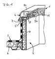
- a smoke and heat exhaust system 1 shown schematically in Figure 1 is located in an opening 2 of a roof 3.
- the roof 3 is provided with an insulation 4, which is also in the interior of the opening 2 of the roof 3.
- the opening 2 in the roof 3 is bounded by a frame 5.
- a flap 6 of the smoke and heat suit 1 is attached to a not shown and therefore not designated hinge hinged.
- the flap 6 of the smoke and heat exhaust system 1 is located on the frame 5.
- sealing elements 7 and 8 are provided, which are located between the frame 5 and a frame 9 which surrounds the flap 6 and corresponds to the frame 5.
- the frame 9 is formed in two parts and consists of a main frame 9a and an auxiliary frame 9b.
- the auxiliary frame 9b receives a disk 10, through which light into the opening 2 of the roof 3 passes.
- the main frame 9a receives the auxiliary frame 9b together with the disk 10.
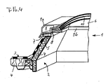
- FIG. 3 shows the special situation in the special emergency.
- a snow load S is stored on the smoke and heat exhaust system 1 and in its environment and prevents it from opening to the outside.
- the conventional solutions do not allow an opening to the outside, since the movement space of the smoke and heat exhaust system 1 is blocked by snow and ice masses S.
- the flap 6 is already opened in accordance with the invention inside and the snow load S is already slid inward in the region of the released opening, so that the area is shown above the opening 2 without snow load.
- the function of the conventional smoke and heat exhaust systems 1 based on the fact that correspondingly large opening areas in the described type of skylights or other mechanically outwardly opening smoke and heat exhaust flaps by means of control and movement elements moves up and be opened to the outside. The warm or hot smoke and fire gases are thereby discharged into the open air.
- the flaps In the case of larger amounts of snow S on the roof 3 of the building, the flaps must raise and displace overlapping snow masses during the opening process. A small portion of the snow masses will slip off the smoke and heat extraction system through the opening process and fall through the resulting opening into the interior of the room. The larger proportion is compressed at corresponding snow masses during the unfolding process and block the further opening of the smoke and heat exhaust system. It should also be taken into account that the forces to be applied for opening rise sharply, since the transition edges around the opening have ice layers which additionally have to be broken up. The function of the smoke and heat exhaust system is therefore no longer guaranteed when resting large amounts of snow.
- the snow and ice masses support by their own weight, the tendency of the flap 6, to open down.
- various locking and unlocking mechanisms offer.
- a known per se thermal locking and unlocking can be provided.
- additional opening energy may not be required.
- pneumatic, hydraulic, mechanical and / or electromechanical devices Such a solution always ensures a reliable opening to the inside when a predetermined temperature is reached in the room.
- the triggering of the opening can also be done via a known per se smoke detectors or other triggering elements.
- retaining elements ensures that the flap 6 when opening can not fall down into the room. This measure prevents additional injury hazards.
- retaining elements are not the subject of the invention, they may be formed as chains, telescopic rods or the like.
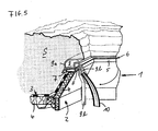
- FIG. 4 shows a further exemplary embodiment in the form of a dome light.
- a smoke and heat exhaust system 1 covers an opening 2 in a roof 3, which is provided with an insulation 4.
- a frame 5 encloses the opening 2 at its upper periphery.
- On the frame 5 is a frame 9 a flap 6, which is open and serves as a smoke and heat exhaust.
- the frame 9 carries a translucent dome 10, which allows an exposure of the room.
- the dome 10 is open by means of the frame 9. It consists of the frame 9 - as in the previous embodiment - consists of two parts, the main frame 9a and the auxiliary frame 9b.
- the flap 6 is moved with the dome 10 by means of the entire frame 9 upwards.
- Serve opening mechanisms as they are well known from the prior art. This is not shown here for this reason and need not be explained in detail.
- the frame 9 is formed in two parts and consists essentially of a main frame 9a and a subframe 9b. With the help of the main frame 9a, the flap 6 can be opened to the outside and with the help of the subframe 9b, the flap 6 can be opened inwards towards the room, which is advantageous in the event of a disaster. Due to a high snow load S, the flap 6 with the dome 10 can not be opened to the outside in case of disaster. However, the two-part frame 9 still allows the maintenance of the smoke and heat dissipating function of the smoke and heat exhaust system by the flap 6 with the dome 10 by means of the subframe 9b can be opened inwardly towards the room.
- FIG. 6 shows a smoke and heat exhaust system 1, in which the auxiliary frame 9b is an integral part of the flap 6 in a particularly advantageous manner.
- This embodiment can provide manufacturing advantages.
- the other components correspond mutatis mutandis to the examples described above and are shown as highly schematic in all drawings.
Landscapes
- Engineering & Computer Science (AREA)
- Architecture (AREA)
- Civil Engineering (AREA)
- Structural Engineering (AREA)
- Mechanical Engineering (AREA)
- Combustion & Propulsion (AREA)
- Chemical & Material Sciences (AREA)
- General Engineering & Computer Science (AREA)
- Building Environments (AREA)
- Power-Operated Mechanisms For Wings (AREA)
- Door And Window Frames Mounted To Openings (AREA)
- Roof Covering Using Slabs Or Stiff Sheets (AREA)
- Specific Sealing Or Ventilating Devices For Doors And Windows (AREA)
Abstract
Description
Die vorliegende Erfindung bezieht sich auf eine Vorrichtung zum Rauch- und Wärmeabzug sowie zum Be-und Entlüften von Räumen.The present invention relates to a device for smoke and heat exhaust ventilation and for ventilation of rooms.
Aus der Praxis sind Vorrichtungen bekannt, bei denen große und schwere Klappen z.B. mittels Zahnstangenantrieben, parallel zur jeweiligen Dachöffnung angehoben werden können.In practice, devices are known in which large and heavy valves, e.g. By means of rack drives, can be raised parallel to the respective roof opening.
Bekannt sind derartige Vorrichtungen beispielsweise auch als Lichtelemente mit einer eine Dachöffnung umgrenzenden Zarge an welcher mittels Scharnier eine Klappe schwenkbar gelagert und an der gegenüber liegenden Zargenseite verriegelbar angeordnet ist. Die Öffnung der Klappe erfolgt mittels Hubelement nach außen.Such devices are also known, for example, as light elements with a frame surrounding a roof opening on which a hinge is pivotally mounted by means of a hinge and is arranged lockable on the opposite side of the frame. The opening of the flap by means of lifting element to the outside.
Solche Lichtelemente können z.B. Lichtkuppeln oder in Dachoberlichtbändern integrierte Lichtklappen sein, die in Öffnungen von flachen oder leicht geneigten Dächern eingebaut sind. Derartige Klappen dienen allgemein dem erforderlichen und vorgeschriebenen Rauch- und Wärmeabzug, vor allem im Katastrophenfall, bei dem sie durch Fernauslösung entweder mit einem selbsttätigen Thermo-Auslöser oder von Hand mit Hilfe eines Hubelements aufgeklappt werden.Such light elements may e.g. Skylight domes or roof skylight integrated light flaps, which are installed in openings of flat or slightly inclined roofs. Such flaps generally serve the required and mandatory smoke and heat extraction, especially in case of disaster, in which they are opened by remote release either with an automatic thermal release or manually by means of a lifting element.
In der
Aus der
Eine weitere Vorrichtung zum Rauch- und Wärmeabzug ist aus der
Die aufgeführten Beispiele sollen die Vielfalt der Möglichkeiten darstellen, dabei ließe sich die Liste der technischen Lösungen ohne weiteres verlängern.The examples given are intended to illustrate the variety of possibilities and the list of technical solutions could easily be extended.
Die zitierten Rauch- und Wärmeabzugsanlagen kurz RWA genannt können jedoch bei bestimmten Wetter-Verhältnissen ihre Funktionsfähigkeit verlieren. Wenn - wie im Winter 2005/2006 - die Schneemassen auf den Dächern von Gebäuden ungewöhnlich hoch sind, werden die RWA vom Schnee überdeckt. Die mechanischen Öffnungseinrichtungen sind nicht mehr in der Lage, die nach oben und außen öffnenden Klappen gegenüber der Schneelast zu bewegen. Im Brandfall hat dies zur Folge, dass die RWA wegen der fehlenden Öffnungsmöglichkeit den Rauch und die Wärme nicht mehr ins Freie ableiten können. Eine Verrauchung der Räume, bzw. der Gebäude ist die Folge und eine Rettung oder ein kontrollierter Löschangriff sind nicht mehr möglich. Darüber hinaus steigt wegen der fehlenden Wärmeableitung die Temperatur im brennenden Gebäude schneller an, als bei der Konzeption des Baus berücksichtigt wurde, so dass negative Auswirkungen auf die Statik der Tragwerke unvermeidbar sind und zum Versagen der Tragwerke führen können.However, the cited smoke and heat exhaust systems called RWA can lose their functionality in certain weather conditions. If, as in the winter of 2005/2006, the snow masses on the roofs of buildings are unusually high, the RWAs are covered by the snow. The mechanical opening devices are no longer able to move the upwardly and outwardly opening flaps against the snow load. In the event of a fire, this means that the RWA can no longer discharge the smoke and heat to the outside due to the lack of opening possibilities. A smoke of the rooms, or the building is the result and a rescue or a controlled fire attack are no longer possible. In addition, due to the lack of heat dissipation, the temperature in the burning building increases faster than was considered in the design of the building, so that adverse effects on the static of the structures are unavoidable and can lead to failure of the structures.
Die bekannten RWA können demnach bei gewissen Wetter-Verhältnissen ihre Funktion nicht mehr gewährleisten, so dass in diesen Fällen hohe Personen- und Sachschäden die Folge sein können.The known RWA can therefore no longer ensure their function in certain weather conditions, so that In these cases, high personal injury and property damage may result.
Der vorliegenden Erfindung liegt daher die Aufgabe zu Grunde, eine Vorrichtung zum Be- und Entlüften von Räumen zu schaffen, die die Nachteile des Standes der Technik nicht aufweist, und die auch bei großen Schneelasten auf ihren Einbauorten den Abzug von Rauch und Wärme gewährleistet beziehungsweise ermöglicht.The present invention is therefore based on the object to provide a device for ventilation of rooms, which does not have the disadvantages of the prior art, and ensures the withdrawal of smoke and heat even at high snow loads on their installation locations ,
Diese Aufgabe wird mit einer Vorrichtung gelöst, welche die Merkmale des Anspruchs 1 oder 12 aufweist.This object is achieved with a device having the features of
Die Vorteile der erfindungsgemäßen Vorrichtung liegen in der hohen Betriebssicherheit und in der Vermeidung oder zumindest Verminderung hoher Personen- und Sachschäden im Brandfall.The advantages of the device according to the invention are in the high reliability and in the prevention or at least reduce high personal injury and property damage in case of fire.
Weitere Vorteile sind den abhängigen Ansprüchen zu entnehmen und im Folgenden kurz aufgelistet:Further advantages can be found in the dependent claims and briefly listed below:
Vorteilhaft ist eine Vorrichtung zum Rauch- und Wärmeabzug sowie zum Be-und Entlüften von Räumen, bei der eine Klappe, an einer eine Dachöffnung umgrenzenden Zarge derart gelagert ist, dass die Dachöffnung mit Hilfe der Klappe zu öffnen und zu schließen ist, wobei die Zarge und die Klappe so ausgebildet sind, dass zumindest eine Öffnung der Klappe nach innen zum Raum hin möglich ist, wobei es besonders vorteilhaft ist, wenn die Klappe parallel zur Zarge nach innen zum Raum hin zu öffnen ist.Advantageous is a device for smoke and heat exhaust ventilation and ventilation of rooms in which a flap, is mounted on a roof opening bounding a frame such that the roof opening with the help of the flap to open and close, the frame and the flap are formed so that at least one opening of the flap is possible inwardly towards the room, wherein it is particularly advantageous if the flap is parallel to the frame inwardly to open towards the room.
Des weiteren ist eine Vorrichtung zum Rauch- und Wärmeabzug sowie zum Be-und Entlüften von Räumen von Vorteil, wenn eine Klappe an einer eine Dachöffnung umgrenzenden Zarge mittels wenigstens einem Scharnier schwenkbar gelagert und an der dem Scharnier gegen-überliegenden Seite verriegelbar ausgebildet ist, und wenn das Scharnier so ausgebildet ist, dass es zumindest eine Öffnung der Klappe nach innen zum Raum hin ermöglicht.Furthermore, an apparatus for smoke and heat extraction and for ventilation of rooms is advantageous if a flap is pivotally mounted on a roof opening bounding a frame by means of at least one hinge and lockable on the hinge opposite side, and if the hinge is designed so that it at least opening the flap inward towards the room.
Darüber hinaus ist es von Vorteil, wenn die Klappe von einem wenigstens zweigeteilten Rahmen derart umsäumt ist, wobei ein Haupt-Rahmen und ein Hilfs-Rahmen gebildet wird, so dass sich die Klappe mittels des Hilfs-Rahmens nach innen zum Raum hin öffnen lässt.Moreover, it is advantageous if the flap is surrounded by an at least two-part frame in such a manner, wherein a main frame and an auxiliary frame is formed, so that the flap can be opened by means of the auxiliary frame inwardly toward the room.
Vorteilhaft ist es außerdem, wenn die Klappe von einem wenigstens zweigeteilten Rahmen derart umsäumt ist, dass ein Haupt-Rahmen und ein Hilfs-Rahmen gebildet wird, und wenn sich die Klappe mittels des Haupt-Rahmens nach außen ins Freie und/oder mittels des Hilfs-Rahmens nach innen zum Raum hin öffnen lässt.It is also advantageous if the flap is framed by an at least two-part frame such that a main frame and an auxiliary frame is formed, and when the flap by means of the main frame to the outside and / or by means of the auxiliary Frame opens inward towards the room.
Ferner ist eine Vorrichtung vorteilhaft, bei der Hilfs-Rahmen integrierter Bestandteil der Klappe ist.Furthermore, a device is advantageous in which the auxiliary frame is an integral part of the flap.
Eine Vorrichtung der genannten Art ist dann besonders vorteilhaft, wenn die Ver- und,Entriegelung der Klappe mittels temperaturempfindlichem Element erfolgt.A device of the type mentioned is particularly advantageous when the locking and unlocking of the flap takes place by means of temperature-sensitive element.
Außerdem kann es vorteilhaft sein, die Ver- und Entriegelung der Klappe mittels rauchempfindlichem Element zu steuern.In addition, it may be advantageous to control the locking and unlocking of the flap by means of a smoke-sensitive element.
Günstig ist eine Klappe, wenn sie eine Lichtdurchlässige Scheibe oder eine Lichtdurchlässige Kuppel aufweist.Conveniently, a flap, if it has a translucent disc or a translucent dome.
Eine Vorrichtung ist auch dann vorteilhaft, wenn die Klappe integrierter Bestandteil eines Lichtbandes ist.A device is also advantageous if the flap is an integral part of a light band.
Die Klappe kann in vorteilhafter Ausgestaltung auch integrierter Bestandteil einer mehrklappigen Rauchabzugseinrichtung oder integrierter Bestandteil einer Licht- und/oder Rauchkuppel sein.In an advantageous embodiment, the flap can also be an integrated component of a multi-flap smoke extraction device or an integrated component of a light and / or smoke dome.
Eine Vorrichtung ist dann besonders vorteilhaft, wenn der Hilfs-Rahmen integrierter Bestandteil einer Licht- und/oder Rauchkuppel ist.A device is particularly advantageous when the auxiliary frame is an integral part of a light and / or smoke dome.
Mit Hilfe von Ausführungsbeispielen wird die Erfindung anhand der Zeichnungen noch näher erläutert.With the aid of exemplary embodiments, the invention will be explained in more detail with reference to the drawings.
Es zeigt
Figur 1 eine Rauch- und Wärmeabzugsanlage im perspektivischen Teilschnitt;Figur 2 die Rauch- und Wärmeabzugsanlage ausFigur 1 mit nach außen geöffnetem Rahmen;Figur 3 die Rauch- und Wärmeabzugsanlage ausFigur 1 mit unter Schneelast nach innen geöffnetem Rahmen;Figur 4 eine Rauch- und Wärmeabzugsanlage in Form einer Lichtkuppel;Figur 5 die Rauch- und Wärmeabzugsanlage gemäßFigur 4 unter Schneelast nach innen geöffnet undFigur 6 eine weitere Variante einer Rauch- und Wärmeabzugsanlage.
- Figure 1 is a smoke and heat exhaust system in perspective partial section;
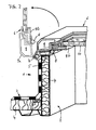
- Figure 2 shows the smoke and heat exhaust system of Figure 1 with the frame open to the outside;
- FIG. 3 shows the smoke and heat exhaust system from FIG. 1 with the frame open inwardly under snow load;
- Figure 4 is a smoke and heat exhaust system in the form of a dome light;
- Figure 5 shows the smoke and heat exhaust system according to Figure 4 under snow load inwardly opened and
- Figure 6 shows another variant of a smoke and heat exhaust system.
Eine in Figur 1 schematisch dargestellte Rauch- und Wärmeabzugsanlage 1 befindet sich in einer Öffnung 2 eines Daches 3. Das Dach 3 ist mit einer Isolierung 4 versehen, welche sich auch in den Innenbereichen der Öffnung 2 des Daches 3 befindet. Die Öffnung 2 im Dach 3 wird von einer Zarge 5 umgrenzt. An der Zarge 5 ist an einem nicht dargestellten und deshalb auch nicht bezeichneten Scharnier eine Klappe 6 der Rauch- und Wärmeanzugsanlage 1 klappbar befestigt. Im dargestellten Bereich liegt die Klappe 6 der Rauch- und Wärmeabzugsanlage 1 auf der Zarge 5 auf. Zur Abdichtung der Klappe 6 gegenüber der Zarge 5 sind Dichtelemente 7 und 8 vorgesehen, die sich zwischen der Zarge 5 und einem Rahmen 9 befinden, welcher die Klappe 6 umgibt und mit der Zarge 5 korrespondiert. Der Rahmen 9 ist' zweiteilig ausgebildet und besteht aus einem Haupt-Rahmen 9a und einem Hilfs-Rahmen 9b. Der Hilfs-Rahmen 9b nimmt eine Scheibe 10 auf, durch welche Licht in die Öffnung 2 des Daches 3 gelangt. Der Haupt-Rahmen 9a nimmt den Hilfs-Rahmen 9b zusammen mit der Scheibe 10 auf.A smoke and
Im Normalfall - welcher in Figur 2 dargestellt ist - kann die Klappe 6 mit Hilfe ihres Rahmens 9 und des nicht dargestellten Scharniers komplett, d.h. zusammen mit dem Haupt-Rahmen 9a, dem Hilfs-Rahmen 9b und der Scheibe 10 nach außen hin geöffnet werden und erlaubt so das Lüften des darunter befindlichen Raums. Diese Normal-Funktion ist in der Figur 2 durch eine aufgestellte Klappe 6 gezeigt, wobei die Variante mit aufgeklappter Klappe 6 in dünneren Linien dargestellt ist. Die Bezugszeichen für gleiche, gleichartige oder gleichwirkende Elemente sind die gleichen wie in Figur 1, was auch bei der Beschreibung der weiteren Figuren gilt. Die in dünneren Linien dargestellte Variante stellt insofern den Normalfall dar, als dieser sowohl das normale Öffnen nach außen hin zum Zwecke der normalen Lüftung umfasst, als auch das Öffnen im Notfall, wenn keine Schnee- und/oder Eislasten das Öffnen nach außen verhindern.Normally - which is shown in Figure 2 - the
In Figur 3 ist die besondere Situation im speziellen Notfall gezeigt. Eine Schneelast S lagert auf der Rauch- und Wärmeabzugsanlage 1 sowie in deren Umfeld und verhindert das Öffnen nach außen. Die herkömmlichen Lösungen lassen ein Öffnen nach außen nicht zu, da der Bewegungsraum der Rauch- und Wärmeabzugsanlage 1 durch Schnee- und Eismassen S blockiert ist. In der Darstellung von Figur 3 ist allerdings die Klappe 6 bereits in erfindungsgemäßer Weise nach innen geöffnet und die Schneelast S ist im Bereich der freigegeben Öffnung bereits nach innen abgerutscht, so dass der Bereich über der Öffnung 2 ohne Schneelast dargestellt ist.FIG. 3 shows the special situation in the special emergency. A snow load S is stored on the smoke and
Die Funktion der herkömmlichen Rauch- und Wärmeabzugsanlagen 1 beruht darauf, dass entsprechend grosse Öffnungsflächen in der beschriebenen Art von Lichtkuppeln oder auch anderen mechanisch nach außen öffnenden Rauch- und Wärmeabzugsklappen mittels Steuer- und Bewegungselementen nach oben bewegt und ins Freie geöffnet werden. Die warmen bzw. heißen Rauch- und Brandgase werden dadurch ins Freie abgeleitet. Im Falle von größeren Schneemassen S auf dem Dach 3 des Gebäudes müssen die Klappen beim Öffnungsvorgang aufliegende Schneemassen anheben und verdrängen. Ein geringer Teil der Schneemassen wird durch den Öffnungsvorgang von der Rauch- und Wärmeabzugsanlage abrutschen und durch die entstehende Öffnung in das Innere des Raumes fallen. Der größere Anteil wird bei entsprechenden Schneemassen beim Aufklappvorgang verdichtet und die weitere Öffnung der Rauch- und Wärmeabzugsanlage blockieren. Zu berücksichtigen ist auch noch, dass die zum Öffnen aufzubringenden Kräfte stark ansteigen, da die Übergangskanten rund um die Öffnung Eisschichten aufweisen, welche zusätzlich aufgebrochen werden müssen. Die Funktion der Rauch- und Wärmeabzugsanlage ist demgemäß beim Aufliegen großer Schneemassen nicht mehr gewährleistet.The function of the conventional smoke and
Hier setzt die Erfindung ein. Durch die besondere Ausbildung des Rahmens 9 mit einem Haupt-Rahmen 9a und einem Hilfs-Rahmen 9b wird eine Öffnung der Klappe 6 nach innen in den Raum hinein ermöglicht. Dazu verbleibt der Haupt-Rahmen 9a in seiner Lage auf der Zarge 5, aber der Hilfs-Rahmen 9b wird nach innen geklappt und gibt eine Öffnung 2 zum Abzug der Wärme und der Rauchgase frei. Dies kann mit Hilfe eines nicht dargestellten und daher nicht näher bezeichneten Scharniers geschehen, wobei die Ausbildung des Scharniers nicht Gegenstand der Erfindung sein soll. Diese Lösung mit einem Doppelrahmen 9a, 9b ermöglicht es, bei den erfindungsgemäßen Rauch- und Wärmeabzugsanlagen 1 eine Klappe 6 auch unter aufliegender Last zu öffnen, und zwar nach innen zum Raum hin. Schnee und Eis fallen dann zwar im den Innenraum, aber der Rauch- und Wärmeabzug kann ungehindert erfolgen, weil die entsprechende Öffnung 2 zum Rauch- und Wärmeabzug freigegeben ist.This is where the invention starts. Due to the special design of the
Die durch das Öffnen der Klappe 6 nach innen herunterfallenden Schnee- und Eisreste stellen zwar eine gewisse potentielle Gefahr für zufällig darunter vorbeilaufende Flüchtende und Hilfskräfte dar, in Bezug auf die Gefahren eines nicht funktionierenden Rauch- und Wärmeabzugs sind diese Gefahren allerdings zu vernachlässigen.The falling down by the opening of the
Die Schnee- und Eismassen unterstützen durch ihr Eigengewicht die Tendenz der Klappe 6, sich nach unten zu öffnen. Für die Klappe 6 bieten sich verschiedene Ver- und Entriegelungsmechanismen an. Beispielsweise kann eine an sich bekannte thermische Ver- und Entriegelung vorgesehen sein. In diesem Fall kann durch die Abstimmung mit dem Eigengewicht der Klappe 6 zusätzliche Öffnungsenergie nicht erforderlich sein. Dennoch kann es vorteilhaft sein, die Absenkung der Klappe durch pneumatische, hydraulische, mechanische und/oder elektromechanische Geräte zu unterstützen. Eine derartige Lösung gewährleistet immer eine zuverlässige Öffnung nach innen, wenn im Raum eine vorbestimmte Temperatur erreicht ist. Die Auslösung der Öffnung kann aber auch über einen an sich bekannten Rauchmelder oder andere Auslöseelemente erfolgen.The snow and ice masses support by their own weight, the tendency of the
Durch an sich ebenfalls bekannte Halteelemente wird sicher gestellt, dass die Klappe 6 beim Öffnen nicht nach unten in den Raum fallen kann. Diese Maßnahme verhindert zusätzliche Verletzungsgefahren. Derartige Halteelemente sind jedoch nicht Gegenstand der Erfindung, sie können als Ketten, Teleskopstäbe oder dergleichen ausgebildet sein. (Scharnier)By per se also known retaining elements ensures that the
In Figur 4 wird ein weiteres Ausführungsbeispiel in Form einer Lichtkuppel dargestellt. Ein Rauch- und Wärmeabzugsanlage 1 deckt eine Öffnung 2 in einem Dach 3 ab, welches mit einer Isolierung 4 versehen ist. Eine Zarge 5 umschließt die Öffnung 2 an ihren oberen Umfang. Auf der Zarge 5 liegt ein Rahmen 9 einer Klappe 6 auf, die zu öffnen ist und als Rauch- und Wärmeabzug dient. Ferner kann mittels der zu öffnenden Klappe 6 der darunter befindliche Raum belüftet werden, wobei der Rahmen 9 eine lichtdurchlässige Kuppel 10 trägt, welche eine Belichtung des Raumes ermöglicht. Die Kuppel 10 ist mittels des Rahmens 9 zu öffnen. Dabei besteht der Rahmen 9 - wie im vorherigen Ausführungsbeispiel - aus zwei Teilen, dem Haupt-Rahmen 9a und dem Hilfs-Rahmen 9b. Bei der normalen Belüftung des Raumes wird die Klappe 6 mit der Kuppel 10 mit Hilfe des gesamten Rahmens 9 nach oben bewegt. Dazu dienen Öffnungsmechanismen, wie sie aus dem Stand der Technik hinreichend bekannt sind. Dies ist aus diesem Grund hier auch nicht gezeigt und braucht auch nicht näher erläutert zu werden.FIG. 4 shows a further exemplary embodiment in the form of a dome light. A smoke and
In Figur 5 wird eine andere Situation gezeigt. Der Rahmen 9 ist zweiteilig ausgebildet und besteht im Wesentlichen aus einem Hauptrahmen 9a und einem Hilfsrahmen 9b. Mit Hilfe des Hauptrahmens 9a lässt sich die Klappe 6 nach außen öffnen und mit Hilfe des Hilfsrahmens 9b lässt sich die Klappe 6 nach innen zum Raum hin öffnen, was im Katastrophenfall vorteilhaft ist. Aufgrund einer hohen Schneelast S kann im Katastrophenfall die Klappe 6 mit der Kuppel 10 nicht nach außen hin geöffnet werden. Der zweiteilige Rahmen 9 ermöglicht aber dennoch die Aufrechterhaltung der Rauch und Wärme ableitenden Funktion der Rauch- und Wärmeabzugsanlage, indem die Klappe 6 mit der Kuppel 10 mit Hilfe des Hilfsrahmens 9b nach innen zum Raum hin geöffnet werden kann. Bei der Darstellung wurde berücksichtigt, dass sich die Klappe 6 bereits nach innen zum Raum hin geöffnet hat, so dass in dieser Situation oberhalb der Klappe 6 keine Schneelast S mehr befindet. Diese ist bereits in den darunter befindlichen Raum abgerutscht. Zu diesem Ausführungsbeispiel gelten uneingeschränkt die Aussagen, die bereits zum vorstehenden Ausführungsbeispiel gemäß der Figuren 1 bis 3 gemacht wurden.In Figure 5, another situation is shown. The
In Figur 6 ist eine Rauch- und Wärmeabzugsanlage 1 dargestellt, bei der in besonders vorteilhafter Weise der Hilfs-Rahmen 9b integraler Bestandteil der Klappe 6 ist. Dieses Ausführungsbeispiel kann fertigungstechnische Vorteile bieten. Die sonstigen Bauelemente entsprechen sinngemäß den vorbeschriebenen Beispielen und sind wie diese in allen Zeichnungen stark schematisiert dargestellt.FIG. 6 shows a smoke and
- 11
- Rauch- und WärmeabzugsanlageSmoke and heat exhaust system
- 22
- Öffnungopening
- 33
- Dachtop, roof
- 44
- Isolierunginsulation
- 55
- Zargeframe
- 66
- Klappeflap
- 77
- Dichtungpoetry
- 88th
- Dichtungpoetry
- 99
- Rahmenframe
- 9a9a
- Hauptrahmenmain frame
- 9b9b
- Hilfsrahmensubframe
- 1010
- Scheibe, LichtkuppelSlice, dome light
Claims (14)
Applications Claiming Priority (1)
| Application Number | Priority Date | Filing Date | Title |
|---|---|---|---|
| DE102006038009A DE102006038009B4 (en) | 2006-08-14 | 2006-08-14 | Device for smoke and heat extraction of rooms |
Publications (3)
| Publication Number | Publication Date |
|---|---|
| EP1898020A2 true EP1898020A2 (en) | 2008-03-12 |
| EP1898020A3 EP1898020A3 (en) | 2010-06-02 |
| EP1898020B1 EP1898020B1 (en) | 2011-10-19 |
Family
ID=38954721
Family Applications (1)
| Application Number | Title | Priority Date | Filing Date |
|---|---|---|---|
| EP07015865A Not-in-force EP1898020B1 (en) | 2006-08-14 | 2007-08-13 | Device for removing smoke and heat from an area |
Country Status (3)
| Country | Link |
|---|---|
| EP (1) | EP1898020B1 (en) |
| AT (1) | ATE529585T1 (en) |
| DE (1) | DE102006038009B4 (en) |
Citations (5)
| Publication number | Priority date | Publication date | Assignee | Title |
|---|---|---|---|---|
| DE2516098A1 (en) | 1974-04-23 | 1975-11-13 | Svenska Icopalfabriken Ab | VENTILATION DEVICE, IN PARTICULAR SMOKE AND FIRE VENTILATION DEVICE |
| DE3345185A1 (en) | 1983-12-14 | 1985-06-27 | Resopal Werk H. Römmler GmbH, 6800 Mannheim | Skylight window |
| DE3338092C2 (en) | 1983-10-20 | 1994-08-04 | Fa. J. Eberspaecher, 7300 Esslingen, De | |
| DE9411812U1 (en) | 1994-07-21 | 1994-09-15 | E M B Metallbau Und Brandschut | Double flap fan as a flap arrangement in the ridge area of a roof or a saddle skylight strip |
| DE29706030U1 (en) | 1997-01-08 | 1997-08-21 | Engelhardt Walter | Smoke and heat exhaust system |
Family Cites Families (9)
| Publication number | Priority date | Publication date | Assignee | Title |
|---|---|---|---|---|
| DE2634565A1 (en) * | 1976-07-31 | 1978-02-02 | Iva Ingenieurgesellschaft Mbh | Opener for combined ventilation and fume extraction - has pivoted cylinder moving flap into partly and fully open position |
| DE2914475A1 (en) * | 1979-04-10 | 1980-10-30 | Eberspaecher J | Building air and smoke vent - has frame with Z=section side walls, whose upper flanges slope inwards and downwards |
| FR2481353A1 (en) * | 1980-04-29 | 1981-10-30 | Yves Fourtane | Fixing for swing door leaf - has hinge on fixed frame and leaf allowing two direction leaf pivoting |
| JPS5761168A (en) * | 1980-09-30 | 1982-04-13 | Nippon Air Brake Co | Skylight operator |
| DD223491A1 (en) * | 1984-04-13 | 1985-06-12 | Berlin Baumechanisierung | UNIVERSAL APPLICATION FLOOR FOR GROUND FLOOR AND LARGE GLAZING |
| US4663905A (en) * | 1986-09-02 | 1987-05-12 | Kenneth Schulz | Skylight assembly |
| DE19534614A1 (en) * | 1995-09-18 | 1997-03-20 | Winkhaus Fa August | Blocking action safety device for door or window |
| DE102004016458B3 (en) * | 2004-03-31 | 2005-03-03 | Wolfgang Stief | Emergency opening mechanism for flat roof smoke ventilation windows has exposed condition indicator pin |
| DE202005012111U1 (en) * | 2005-08-02 | 2005-12-15 | PARAT Automotive Schönenbach GmbH + Co. KG | Window frame for use in e.g. automobile, has two frame parts, where one part frames an aperture in a wall or inserted in a wall, and frame rails exhibiting linear tracks for lateral holder units at opening of shading medium |
-
2006
- 2006-08-14 DE DE102006038009A patent/DE102006038009B4/en not_active Expired - Fee Related
-
2007
- 2007-08-13 EP EP07015865A patent/EP1898020B1/en not_active Not-in-force
- 2007-08-13 AT AT07015865T patent/ATE529585T1/en active
Patent Citations (5)
| Publication number | Priority date | Publication date | Assignee | Title |
|---|---|---|---|---|
| DE2516098A1 (en) | 1974-04-23 | 1975-11-13 | Svenska Icopalfabriken Ab | VENTILATION DEVICE, IN PARTICULAR SMOKE AND FIRE VENTILATION DEVICE |
| DE3338092C2 (en) | 1983-10-20 | 1994-08-04 | Fa. J. Eberspaecher, 7300 Esslingen, De | |
| DE3345185A1 (en) | 1983-12-14 | 1985-06-27 | Resopal Werk H. Römmler GmbH, 6800 Mannheim | Skylight window |
| DE9411812U1 (en) | 1994-07-21 | 1994-09-15 | E M B Metallbau Und Brandschut | Double flap fan as a flap arrangement in the ridge area of a roof or a saddle skylight strip |
| DE29706030U1 (en) | 1997-01-08 | 1997-08-21 | Engelhardt Walter | Smoke and heat exhaust system |
Also Published As
| Publication number | Publication date |
|---|---|
| ATE529585T1 (en) | 2011-11-15 |
| DE102006038009A1 (en) | 2008-02-21 |
| EP1898020B1 (en) | 2011-10-19 |
| DE102006038009B4 (en) | 2011-04-28 |
| EP1898020A3 (en) | 2010-06-02 |
Similar Documents
| Publication | Publication Date | Title |
|---|---|---|
| DE2239438C3 (en) | Double-shell facade element for buildings | |
| EP1703066A2 (en) | Fire and smokeproof door | |
| DE102014115452B4 (en) | Closure arrangement on a ventilation opening in a ceiling of an elevator shaft | |
| DE102007010261B4 (en) | Device for automatically closing a window tilt wing to protect against the ingress of water | |
| EP1898020B1 (en) | Device for removing smoke and heat from an area | |
| EP3643849B1 (en) | Flap for roof, ceiling or façade | |
| DE202006012471U1 (en) | Smoke and heat removal device e.g. for rooms, has lockable flap and provided at trim circumscribing roof aperture with hinge provided being tiltably stored and which faces side | |
| AT521543B1 (en) | Protective device for roller and sectional doors | |
| EP2614706B1 (en) | Roof ridge construction | |
| EP3853425B1 (en) | Multi-storey building with secure access routes and escape routes in the event of fire | |
| EP0656451A1 (en) | Ventilating apparatus for building roofs | |
| AT522398B1 (en) | Hinged bulkhead | |
| DE2458497A1 (en) | Small substation ventilation duct - with self closing shutters inhibiting excape of hot gases during fault | |
| DE202020003790U1 (en) | Roof window arrangement | |
| WO2023070143A1 (en) | Film tunnel for roadways | |
| DE2150453A1 (en) | WORK PLATFORM FOR PERFORMING WORK ON BUILDING BUILDINGS | |
| DE202020106177U1 (en) | Closing with valve device | |
| DE102005040824B4 (en) | dormer | |
| EP3587696A1 (en) | Openable room closure device and method for opening same | |
| DE202009012206U1 (en) | Roof for a construction inside a building | |
| EP3741951A1 (en) | Overflow element for water for extingushing fire | |
| DE2612453A1 (en) | Fume and heat removing roof hood - has hinged hood halves and vertically sliding protecting plates | |
| DE2749246A1 (en) | Venetian-blind type ventilator - has slats with upright edges extending clear of frame | |
| DE102007021824A1 (en) | Wind-insensitive construction of a conservatory | |
| CH656411A5 (en) | REMOVABLE CONSTRUCTION. |
Legal Events
| Date | Code | Title | Description |
|---|---|---|---|
| PUAI | Public reference made under article 153(3) epc to a published international application that has entered the european phase |
Free format text: ORIGINAL CODE: 0009012 |
|
| AK | Designated contracting states |
Kind code of ref document: A2 Designated state(s): AT BE BG CH CY CZ DE DK EE ES FI FR GB GR HU IE IS IT LI LT LU LV MC MT NL PL PT RO SE SI SK TR |
|
| AX | Request for extension of the european patent |
Extension state: AL BA HR MK YU |
|
| PUAL | Search report despatched |
Free format text: ORIGINAL CODE: 0009013 |
|
| AK | Designated contracting states |
Kind code of ref document: A3 Designated state(s): AT BE BG CH CY CZ DE DK EE ES FI FR GB GR HU IE IS IT LI LT LU LV MC MT NL PL PT RO SE SI SK TR |
|
| AX | Request for extension of the european patent |
Extension state: AL BA HR MK RS |
|
| 17P | Request for examination filed |
Effective date: 20101129 |
|
| AKX | Designation fees paid |
Designated state(s): AT BE BG CH CY CZ DE DK EE ES FI FR GB GR HU IE IS IT LI LT LU LV MC MT NL PL PT RO SE SI SK TR |
|
| GRAP | Despatch of communication of intention to grant a patent |
Free format text: ORIGINAL CODE: EPIDOSNIGR1 |
|
| RIC1 | Information provided on ipc code assigned before grant |
Ipc: E04D 13/03 20060101AFI20110315BHEP Ipc: F24F 7/02 20060101ALI20110315BHEP |
|
| GRAS | Grant fee paid |
Free format text: ORIGINAL CODE: EPIDOSNIGR3 |
|
| GRAA | (expected) grant |
Free format text: ORIGINAL CODE: 0009210 |
|
| AK | Designated contracting states |
Kind code of ref document: B1 Designated state(s): AT BE BG CH CY CZ DE DK EE ES FI FR GB GR HU IE IS IT LI LT LU LV MC MT NL PL PT RO SE SI SK TR |
|
| REG | Reference to a national code |
Ref country code: GB Ref legal event code: FG4D Free format text: NOT ENGLISH |
|
| REG | Reference to a national code |
Ref country code: CH Ref legal event code: EP |
|
| REG | Reference to a national code |
Ref country code: IE Ref legal event code: FG4D |
|
| REG | Reference to a national code |
Ref country code: DE Ref legal event code: R096 Ref document number: 502007008406 Country of ref document: DE Effective date: 20111215 |
|
| REG | Reference to a national code |
Ref country code: NL Ref legal event code: VDEP Effective date: 20111019 |
|
| LTIE | Lt: invalidation of european patent or patent extension |
Effective date: 20111019 |
|
| PG25 | Lapsed in a contracting state [announced via postgrant information from national office to epo] |
Ref country code: LT Free format text: LAPSE BECAUSE OF FAILURE TO SUBMIT A TRANSLATION OF THE DESCRIPTION OR TO PAY THE FEE WITHIN THE PRESCRIBED TIME-LIMIT Effective date: 20111019 Ref country code: IS Free format text: LAPSE BECAUSE OF FAILURE TO SUBMIT A TRANSLATION OF THE DESCRIPTION OR TO PAY THE FEE WITHIN THE PRESCRIBED TIME-LIMIT Effective date: 20120219 |
|
| REG | Reference to a national code |
Ref country code: IE Ref legal event code: FD4D |
|
| PG25 | Lapsed in a contracting state [announced via postgrant information from national office to epo] |
Ref country code: LV Free format text: LAPSE BECAUSE OF FAILURE TO SUBMIT A TRANSLATION OF THE DESCRIPTION OR TO PAY THE FEE WITHIN THE PRESCRIBED TIME-LIMIT Effective date: 20111019 Ref country code: SI Free format text: LAPSE BECAUSE OF FAILURE TO SUBMIT A TRANSLATION OF THE DESCRIPTION OR TO PAY THE FEE WITHIN THE PRESCRIBED TIME-LIMIT Effective date: 20111019 Ref country code: GR Free format text: LAPSE BECAUSE OF FAILURE TO SUBMIT A TRANSLATION OF THE DESCRIPTION OR TO PAY THE FEE WITHIN THE PRESCRIBED TIME-LIMIT Effective date: 20120120 Ref country code: SE Free format text: LAPSE BECAUSE OF FAILURE TO SUBMIT A TRANSLATION OF THE DESCRIPTION OR TO PAY THE FEE WITHIN THE PRESCRIBED TIME-LIMIT Effective date: 20111019 Ref country code: PT Free format text: LAPSE BECAUSE OF FAILURE TO SUBMIT A TRANSLATION OF THE DESCRIPTION OR TO PAY THE FEE WITHIN THE PRESCRIBED TIME-LIMIT Effective date: 20120220 Ref country code: NL Free format text: LAPSE BECAUSE OF FAILURE TO SUBMIT A TRANSLATION OF THE DESCRIPTION OR TO PAY THE FEE WITHIN THE PRESCRIBED TIME-LIMIT Effective date: 20111019 |
|
| PG25 | Lapsed in a contracting state [announced via postgrant information from national office to epo] |
Ref country code: CY Free format text: LAPSE BECAUSE OF FAILURE TO SUBMIT A TRANSLATION OF THE DESCRIPTION OR TO PAY THE FEE WITHIN THE PRESCRIBED TIME-LIMIT Effective date: 20111019 |
|
| PG25 | Lapsed in a contracting state [announced via postgrant information from national office to epo] |
Ref country code: DK Free format text: LAPSE BECAUSE OF FAILURE TO SUBMIT A TRANSLATION OF THE DESCRIPTION OR TO PAY THE FEE WITHIN THE PRESCRIBED TIME-LIMIT Effective date: 20111019 Ref country code: CZ Free format text: LAPSE BECAUSE OF FAILURE TO SUBMIT A TRANSLATION OF THE DESCRIPTION OR TO PAY THE FEE WITHIN THE PRESCRIBED TIME-LIMIT Effective date: 20111019 Ref country code: BG Free format text: LAPSE BECAUSE OF FAILURE TO SUBMIT A TRANSLATION OF THE DESCRIPTION OR TO PAY THE FEE WITHIN THE PRESCRIBED TIME-LIMIT Effective date: 20120119 Ref country code: IE Free format text: LAPSE BECAUSE OF FAILURE TO SUBMIT A TRANSLATION OF THE DESCRIPTION OR TO PAY THE FEE WITHIN THE PRESCRIBED TIME-LIMIT Effective date: 20111019 Ref country code: EE Free format text: LAPSE BECAUSE OF FAILURE TO SUBMIT A TRANSLATION OF THE DESCRIPTION OR TO PAY THE FEE WITHIN THE PRESCRIBED TIME-LIMIT Effective date: 20111019 Ref country code: SK Free format text: LAPSE BECAUSE OF FAILURE TO SUBMIT A TRANSLATION OF THE DESCRIPTION OR TO PAY THE FEE WITHIN THE PRESCRIBED TIME-LIMIT Effective date: 20111019 |
|
| PLBE | No opposition filed within time limit |
Free format text: ORIGINAL CODE: 0009261 |
|
| STAA | Information on the status of an ep patent application or granted ep patent |
Free format text: STATUS: NO OPPOSITION FILED WITHIN TIME LIMIT |
|
| PG25 | Lapsed in a contracting state [announced via postgrant information from national office to epo] |
Ref country code: RO Free format text: LAPSE BECAUSE OF FAILURE TO SUBMIT A TRANSLATION OF THE DESCRIPTION OR TO PAY THE FEE WITHIN THE PRESCRIBED TIME-LIMIT Effective date: 20111019 Ref country code: IT Free format text: LAPSE BECAUSE OF FAILURE TO SUBMIT A TRANSLATION OF THE DESCRIPTION OR TO PAY THE FEE WITHIN THE PRESCRIBED TIME-LIMIT Effective date: 20111019 Ref country code: PL Free format text: LAPSE BECAUSE OF FAILURE TO SUBMIT A TRANSLATION OF THE DESCRIPTION OR TO PAY THE FEE WITHIN THE PRESCRIBED TIME-LIMIT Effective date: 20111019 |
|
| 26N | No opposition filed |
Effective date: 20120720 |
|
| REG | Reference to a national code |
Ref country code: DE Ref legal event code: R097 Ref document number: 502007008406 Country of ref document: DE Effective date: 20120720 |
|
| BERE | Be: lapsed |
Owner name: HEWENER, HERMANN Effective date: 20120831 |
|
| REG | Reference to a national code |
Ref country code: CH Ref legal event code: PL |
|
| PG25 | Lapsed in a contracting state [announced via postgrant information from national office to epo] |
Ref country code: MC Free format text: LAPSE BECAUSE OF NON-PAYMENT OF DUE FEES Effective date: 20120831 |
|
| GBPC | Gb: european patent ceased through non-payment of renewal fee |
Effective date: 20120813 |
|
| PG25 | Lapsed in a contracting state [announced via postgrant information from national office to epo] |
Ref country code: CH Free format text: LAPSE BECAUSE OF NON-PAYMENT OF DUE FEES Effective date: 20120831 Ref country code: LI Free format text: LAPSE BECAUSE OF NON-PAYMENT OF DUE FEES Effective date: 20120831 |
|
| REG | Reference to a national code |
Ref country code: FR Ref legal event code: ST Effective date: 20130430 |
|
| PG25 | Lapsed in a contracting state [announced via postgrant information from national office to epo] |
Ref country code: BE Free format text: LAPSE BECAUSE OF NON-PAYMENT OF DUE FEES Effective date: 20120831 |
|
| PG25 | Lapsed in a contracting state [announced via postgrant information from national office to epo] |
Ref country code: FI Free format text: LAPSE BECAUSE OF FAILURE TO SUBMIT A TRANSLATION OF THE DESCRIPTION OR TO PAY THE FEE WITHIN THE PRESCRIBED TIME-LIMIT Effective date: 20111019 |
|
| PG25 | Lapsed in a contracting state [announced via postgrant information from national office to epo] |
Ref country code: GB Free format text: LAPSE BECAUSE OF NON-PAYMENT OF DUE FEES Effective date: 20120813 Ref country code: DE Free format text: LAPSE BECAUSE OF NON-PAYMENT OF DUE FEES Effective date: 20130301 |
|
| PG25 | Lapsed in a contracting state [announced via postgrant information from national office to epo] |
Ref country code: FR Free format text: LAPSE BECAUSE OF NON-PAYMENT OF DUE FEES Effective date: 20120831 |
|
| REG | Reference to a national code |
Ref country code: DE Ref legal event code: R119 Ref document number: 502007008406 Country of ref document: DE Effective date: 20130301 |
|
| REG | Reference to a national code |
Ref country code: AT Ref legal event code: MM01 Ref document number: 529585 Country of ref document: AT Kind code of ref document: T Effective date: 20120831 |
|
| PG25 | Lapsed in a contracting state [announced via postgrant information from national office to epo] |
Ref country code: AT Free format text: LAPSE BECAUSE OF NON-PAYMENT OF DUE FEES Effective date: 20120831 Ref country code: ES Free format text: LAPSE BECAUSE OF FAILURE TO SUBMIT A TRANSLATION OF THE DESCRIPTION OR TO PAY THE FEE WITHIN THE PRESCRIBED TIME-LIMIT Effective date: 20120130 |
|
| PG25 | Lapsed in a contracting state [announced via postgrant information from national office to epo] |
Ref country code: MT Free format text: LAPSE BECAUSE OF FAILURE TO SUBMIT A TRANSLATION OF THE DESCRIPTION OR TO PAY THE FEE WITHIN THE PRESCRIBED TIME-LIMIT Effective date: 20111019 |
|
| PG25 | Lapsed in a contracting state [announced via postgrant information from national office to epo] |
Ref country code: TR Free format text: LAPSE BECAUSE OF FAILURE TO SUBMIT A TRANSLATION OF THE DESCRIPTION OR TO PAY THE FEE WITHIN THE PRESCRIBED TIME-LIMIT Effective date: 20111019 |
|
| PG25 | Lapsed in a contracting state [announced via postgrant information from national office to epo] |
Ref country code: LU Free format text: LAPSE BECAUSE OF NON-PAYMENT OF DUE FEES Effective date: 20120813 |
|
| PG25 | Lapsed in a contracting state [announced via postgrant information from national office to epo] |
Ref country code: HU Free format text: LAPSE BECAUSE OF FAILURE TO SUBMIT A TRANSLATION OF THE DESCRIPTION OR TO PAY THE FEE WITHIN THE PRESCRIBED TIME-LIMIT Effective date: 20070813 |