EP1896331B1 - Vorrichtung zum einbringen von klebstoff in ein beheizbares leimwerk - Google Patents
Vorrichtung zum einbringen von klebstoff in ein beheizbares leimwerk Download PDFInfo
- Publication number
- EP1896331B1 EP1896331B1 EP06776084A EP06776084A EP1896331B1 EP 1896331 B1 EP1896331 B1 EP 1896331B1 EP 06776084 A EP06776084 A EP 06776084A EP 06776084 A EP06776084 A EP 06776084A EP 1896331 B1 EP1896331 B1 EP 1896331B1
- Authority
- EP
- European Patent Office
- Prior art keywords
- receiving device
- heatable
- tubular body
- adhesive
- pasting
- Prior art date
- Legal status (The legal status is an assumption and is not a legal conclusion. Google has not performed a legal analysis and makes no representation as to the accuracy of the status listed.)
- Not-in-force
Links
- 239000000853 adhesive Substances 0.000 title claims abstract description 18
- 230000001070 adhesive effect Effects 0.000 title claims abstract description 18
- 238000010438 heat treatment Methods 0.000 claims abstract description 6
- 238000002372 labelling Methods 0.000 claims description 4
- 229910052782 aluminium Inorganic materials 0.000 claims description 3
- XAGFODPZIPBFFR-UHFFFAOYSA-N aluminium Chemical compound [Al] XAGFODPZIPBFFR-UHFFFAOYSA-N 0.000 claims description 3
- RYGMFSIKBFXOCR-UHFFFAOYSA-N Copper Chemical compound [Cu] RYGMFSIKBFXOCR-UHFFFAOYSA-N 0.000 claims description 2
- 229910052802 copper Inorganic materials 0.000 claims description 2
- 239000010949 copper Substances 0.000 claims description 2
- 239000000463 material Substances 0.000 claims description 2
- 230000004308 accommodation Effects 0.000 claims 1
- 239000004411 aluminium Substances 0.000 claims 1
- 230000037431 insertion Effects 0.000 claims 1
- 238000003780 insertion Methods 0.000 claims 1
- 238000004026 adhesive bonding Methods 0.000 abstract description 14
- 239000004831 Hot glue Substances 0.000 description 3
- 239000003292 glue Substances 0.000 description 3
- 229910052751 metal Inorganic materials 0.000 description 3
- 239000002184 metal Substances 0.000 description 3
- 239000000126 substance Substances 0.000 description 3
- 238000005485 electric heating Methods 0.000 description 2
- 210000002414 leg Anatomy 0.000 description 2
- 238000000034 method Methods 0.000 description 2
- 239000004020 conductor Substances 0.000 description 1
- 230000009969 flowable effect Effects 0.000 description 1
- 210000003127 knee Anatomy 0.000 description 1
- 239000007791 liquid phase Substances 0.000 description 1
- 238000004806 packaging method and process Methods 0.000 description 1
- 230000002093 peripheral effect Effects 0.000 description 1
- 230000000630 rising effect Effects 0.000 description 1
- 238000007790 scraping Methods 0.000 description 1
- XLYOFNOQVPJJNP-UHFFFAOYSA-N water Substances O XLYOFNOQVPJJNP-UHFFFAOYSA-N 0.000 description 1
Images


Classifications
-
- B—PERFORMING OPERATIONS; TRANSPORTING
- B65—CONVEYING; PACKING; STORING; HANDLING THIN OR FILAMENTARY MATERIAL
- B65C—LABELLING OR TAGGING MACHINES, APPARATUS, OR PROCESSES
- B65C9/00—Details of labelling machines or apparatus
- B65C9/20—Gluing the labels or articles
- B65C9/22—Gluing the labels or articles by wetting, e.g. by applying liquid glue or a liquid to a dry glue coating
-
- B—PERFORMING OPERATIONS; TRANSPORTING
- B05—SPRAYING OR ATOMISING IN GENERAL; APPLYING FLUENT MATERIALS TO SURFACES, IN GENERAL
- B05C—APPARATUS FOR APPLYING FLUENT MATERIALS TO SURFACES, IN GENERAL
- B05C11/00—Component parts, details or accessories not specifically provided for in groups B05C1/00 - B05C9/00
- B05C11/10—Storage, supply or control of liquid or other fluent material; Recovery of excess liquid or other fluent material
- B05C11/1042—Storage, supply or control of liquid or other fluent material; Recovery of excess liquid or other fluent material provided with means for heating or cooling the liquid or other fluent material in the supplying means upstream of the applying apparatus
-
- B—PERFORMING OPERATIONS; TRANSPORTING
- B29—WORKING OF PLASTICS; WORKING OF SUBSTANCES IN A PLASTIC STATE IN GENERAL
- B29B—PREPARATION OR PRETREATMENT OF THE MATERIAL TO BE SHAPED; MAKING GRANULES OR PREFORMS; RECOVERY OF PLASTICS OR OTHER CONSTITUENTS OF WASTE MATERIAL CONTAINING PLASTICS
- B29B13/00—Conditioning or physical treatment of the material to be shaped
- B29B13/02—Conditioning or physical treatment of the material to be shaped by heating
- B29B13/022—Melting the material to be shaped
-
- B—PERFORMING OPERATIONS; TRANSPORTING
- B29—WORKING OF PLASTICS; WORKING OF SUBSTANCES IN A PLASTIC STATE IN GENERAL
- B29K—INDEXING SCHEME ASSOCIATED WITH SUBCLASSES B29B, B29C OR B29D, RELATING TO MOULDING MATERIALS OR TO MATERIALS FOR MOULDS, REINFORCEMENTS, FILLERS OR PREFORMED PARTS, e.g. INSERTS
- B29K2105/00—Condition, form or state of moulded material or of the material to be shaped
- B29K2105/0097—Glues or adhesives, e.g. hot melts or thermofusible adhesives
Definitions
- the invention relates to a device for introducing non-flowable at room temperature adhesives in heatable gluing plants according to the preamble of claim 1 and as from US 5,775,542 known.
- Gluing machines of labeling or other packaging machines usually have a reservoir with integrated heater for the adhesive to bring it to the required processing temperature at which the adhesive is then in liquid phase (see Figs. 14-17 of DE 29 41 458 A1 or DE 91 02 068 U ).
- This may be, for example, a UV-curable hot glue (eg KRONES-colfix HM 3002) which is of waxy consistency at room temperature and is supplied bottled in transport containers such as metal cans or the like by the manufacturer.
- the processing temperature in the gluing plant is in the range between 100 and 120 degrees Celsius.
- the problem is the introduction of the rigid adhesive in the reservoir of a gluing plant. So far, the adhesive had to be softened in a hot water bath or removed by scraping from the metal cans. Both methods are cumbersome and time consuming.
- the US 5,775,542 discloses a method for emptying a tank filled with a fusible substance.
- the tank is placed in a clamping device in which the tank is placed over a pivoting device with the tank opening down on a container.
- the container and the tank are heated, causing the substance to melt and flow into a tub from which the substance is further processed.
- a heatable receiving device for the adhesive transport container which is rigid or detachable with the reservoir of a gluing plant in Intervention is according to claim 1.
- the transport container occupies an overhead position in the receiving device, ie its open mouth points down to the filling opening of the reservoir.
- the cradle may be active, e.g. Heat is applied via electrical heating elements or the like, or heated passively by heat conduction from the heated storage tank.
- the receiving device has a with the transport container, in particular its peripheral surface, as fully as possible contactable heat transfer surface.
- This is preferably formed by a tensionable strapping of a particularly good heat conducting material, such as aluminum or copper. Due to the strapping strapping on the one hand a tight, by dimensional tolerances of the transport container largely independent application of the heat transfer surface to the surface of the transport container possible, and on the other hand, a transport container can be quickly replaced by the emptying into the reservoir of gluing plant by a full transport container by the example Toggle quick release generating bias is canceled.
- the receiving device is made detachable from the reservoir to facilitate the replacement of the transport container.
- the receiving device is designed to be pluggable in conjunction with a centering at the filling of the reservoir and can with a Quick release device in the operating position reliably be set on the reservoir.
- the receiving device A according to Fig. 1 consists essentially of a tubular body R with a laterally attached handle H and a centering ring Z having support plate T.
- the centering Z surrounds a in Fig. 3 illustrated circular opening ⁇ in the support plate T.
- Gluing unit L shown a labeling machine for bottles, cans or the like. Article arranged, for example, mounted on the top of a swivel joint.
- the gluing unit L can be heated in a manner known per se with electric heating elements E in the storage container V.
- the tubular body R consists of a circular bent sheet metal and has a running over its entire length slot S.
- the two at the slot S to each other pointing edges of the sheet are each bent approximately -U-shaped outwards and form receiving legs for toggle quick release K and its clamping hook P.
- the toggle quick release K consist in a known manner from a pivot lever with a pivotally hinged thereto bracket which engages positively in a arranged on the opposite receiving leg clamping hook P. Like from the Fig. 1 can be seen, a total of three toggle lever clamps K are arranged at regular intervals one above the other on Rohrköper R.
- the toggle quick release K springs the tubular body R apart in the region of the slot S and thereby increases its inner diameter, if he is not in the centering Z with its lower end.
- the tube body R can be slipped over a filled with room temperature rigid adhesive can.
- the toggle quick release K By closing the toggle quick release K, the tubular body R snugly engages the lateral surface of the preferably metallic can (not shown) and forms a frictional strapping.
- the open can mouth pointing downwards the tubular body R can be inserted from above into the opening of the centering ring Z until its end face rests on an inward, not shown, shoulder surface of the centering ring.
- the knee lever quick-releases K 'mounted on the side of the tubular body R the tubular body R can be permanently fixed to the centering ring Z.
- Both the support plate T with the centering ring Z welded thereto and the tubular body R consist of a Material with good thermal conductivity. Aluminum is particularly suitable for this. Passive heating of the Rohrköpers R via the support plate T and the centering Z. From the tube body R, the heat is transferred to the strapped can and the adhesive, which gradually liquefies by increasing the temperature by the heat rising in the reservoir V of Glue L upward and flows down into the reservoir V.
- the gluing unit L is part of a labeling machine for furnishing bottles or the like. Vessels with, for example, wrap-around labels, which are provided with a vertical glue strip at their vertical edges before being wound up.
- the glue is preferably a hot glue, in particular a UV curable hot glue.
Landscapes
- Physics & Mathematics (AREA)
- Thermal Sciences (AREA)
- Engineering & Computer Science (AREA)
- Mechanical Engineering (AREA)
- Labeling Devices (AREA)
- Coating Apparatus (AREA)
- Adhesives Or Adhesive Processes (AREA)
Description
- Die Erfindung betrifft eine Vorrichtung zum Einbringen von bei Raumtemperatur nicht fließfähigen Klebstoffen in beheizbare Leimwerke gemäß dem Oberbegriff des Anspruchs 1 und wie aus
US 5,775,542 bekannt. - Leimwerke von Etikettier- oder sonstigen Verpackungsmaschinen haben in der Regel einen Vorratsbehälter mit integrierter Heizung für den Klebstoff, um diesen auf die erforderliche Verarbeitungstemperatur zu bringen, bei der der Klebstoff dann in flüssiger Phase vorliegt (siehe Fig. 14-17 von
DE 29 41 458 A1 oderDE 91 02 068 U ). Dabei kann es sich beispielsweise um einen UV-aushärtbaren HeißLeim (z.B. KRONES-colfix HM 3002) handeln, der bei Raumtemperatur von wachsartiger Konsistenz ist und in Transportbehältern wie Metalldosen oder dgl. abgefüllt vom Hersteller beliefert wird. Die verarbeitungstemperatur im Leimwerk liegt im Bereich zwischen 100 -120 Grad Celsius. Problematisch ist das Einbringen des starren Klebstoffes in den Vorratsbehälter eines Leimwerks. Bislang musste der Klebstoff in einem heißen Wasserbad zum Erweichen gebracht oder durch Schaben aus den Metalldosen entnommen werden. Beide Methoden sind umständlich und zeitintensiv. - Aus diesem Grund wird bei einer in der
US 1,768,488 offenbarten Vorrichtung der Klebstoff-Transportbehälter von einer Halteeinrichtung mit der Öffnung nach unten gehalten. Unterhalb der Halteeinrichtung ist eine Heizspirale angebracht, über den die Halteeinrichtung und indirekt auch der Klebstoff-Transportbehälter beheizt werden. Dadurch verflüssigt sich der Klebstoff und fließt in einen Trog, von wo aus er weiterverarbeitet wird. - Die
US 5,775,542 offenbart ein Verfahren zur Entleerung eines Tanks der mit einer schmelzbaren Substanz gefüllt ist. Der Tank wird in eine Klemmvorrichtung eingebracht, in der der Tank über eine Schwenkvorrichtung mit der Tanköffnung nach unten auf einen Behälter aufgesetzt wird. Der Behälter und der Tank werden beheizt, wodurch die Substanz schmilzt und in eine Wanne fließt, von der aus die Substanz weiterverarbeitet wird. - Nachteilig bei diesen Lösungen ist jedoch, dass kein optimaler Sitz des Leim-Transportbehälters auf der Halteeinrichtung bzw. auf dem aufzusetzenden Behälter, insbesondere dem Vorratsbehälter eines Leimwerks garantiert ist.
- Demgegenüber soll eine verbesserte Klebstoffeinbringung in den Vorratsbehälter eines Leimwerks angegeben werden.
- Gelöst wird die Aufgabe durch eine beheizbare Aufnahmevorrichtung für den Klebstoff-Transportbehälter, die starr oder lösbar mit dem Vorratsbehälter eines Leimwerks in Eingriff steht gemäß Anspruch 1. Der Transportbehälter nimmt in der Aufnahmevorrichtung eine Überkopfstellung ein, d.h. seine offene Mündung weist nach unten zur Einfüllöffnung des Vorratsbehälters.
- Die Aufnahmevorrichtung kann aktiv, z.B. über elektrische Heizelemente oder dgl. mit Wärme beaufschlagt, oder passiv durch Wärmeleitung vom beheizten Vorratsbehälter erwärmt werden.
- Um eine schnelle verflüssigung des zunächst noch starren Klebstoffes im Transportbehälter zu erreichen, besitzt die Aufnahmevorrichtung eine mit dem Transportbehälter, insbesondere dessen Umfangfläche, möglichst vollflächig in Kontakt bringbare Wärmeübertragungsfläche. Diese wird bevorzugt durch eine spannbare Umreifung aus einem besonders gut wärmeleitenden Werkstoff, wie Aluminium oder Kupfer gebildet. Durch die vorspannbare Umreifung ist einerseits ein enges, von Maßtoleranzen des Transportbehälters weitgehend unabhängiges Anlegen der Wärmeübertragungsfläche an die Oberfläche des Transportbehälters möglich, und andererseits kann ein Transportbehälter nach dem Entleeren in den Vorratsbehälter des Leimwerks schnell durch einen vollen Transportbehälter ersetzt werden, indem die beispielsweise über Kniehebelschnellspanner erzeugbare Vorspannung aufgehoben wird.
- Bevorzugt ist die Aufnahmevorrichtung vom Vorratsbehälter lösbar ausgeführt, um den Austausch der Transportbehälter zu erleichtern. Zu diesem Zweck ist die Aufnahmevorrichtung in Verbindung mit einem Zentrierstück an der Befüllöffnung des Vorratsbehälters steckbar ausgeführt und kann mit einer Schnellspannvorrichtung in der Betriebstellung zuverlässig am Vorratsbehälter festgelegt werden.
- Nachfolgend wird eine bevorzugte Ausführungsform anhand der Fig. beschrieben. Es zeigt:
- Fig. 1
- eine Aufnahmevorrichtung in einer perspektivischen Darstellung,
- Fig. 2
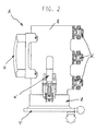
- eine Seitenansicht der Aufnahmevorrichtung,
- Fig. 3
- eine Draufsicht der Aufnahmevorrichtung und
- Fig. 4
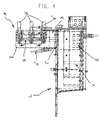
- eine Seitenansicht eines Leimwerks mit der Aufnahmevorrichtung nach den
Fig. 1 bis 3 . - Die Aufnahmevorrichtung A gemäß
Fig. 1 besteht im Wesentlichen aus einem Rohrkörper R mit einem seitlich angesetzten Handgriff H und einer einen Zentrierring Z aufweisenden Tragplatte T. Der Zentrierring Z umgibt eine inFig. 3 dargestellte kreisrunde Öffnung Ö in der Tragplatte T. - Die Tragplatte T ist über der Einfüllöffnung des Vorratsbehälters V eines in
Fig. 4 dargestellten Leimwerks L einer Etikettiermaschine für Flaschen, Dosen oder dgl. Artikel angeordnet, beispielsweise um ein auf der Oberseite angebrachtes Schwenkgelenk. Das Leimwerk L ist in an sich bekannter Weise mit elektrischen Heizelemeten E im Vorratsbehälter V beheizbar. - Der Rohrkörper R besteht aus einem kreisrund gebogenen Blech und besitzt einen über seine gesamte Länge durchgehend verlaufenden Schlitz S. Die beiden am Schlitz S zueinander weisenden Ränder des Blechs sind jeweils annähernd -U-förmig nach außen gebogen und bilden Aufnahmeschenkel für Kniehebelschnellspanner K und deren Spannhaken P.
- Die Kniehebelschnellspanner K bestehen in bekannter Weise aus einem Schwenkhebel mit einem daran schwenkbar angelenkten Bügel, der in einen auf dem gegenüberliegenden Aufnahmeschenkel angeordneten Spannhaken P formschlüssig eingreift. Wie aus der
Fig. 1 zu erkennen ist, sind insgesamt drei Kniehebelschnellspanner K in gleichmäßigen Abständen übereinander am Rohrköper R angeordnet. - Im geöffneten Zustand der Kniehebelschnellspanner K federt der Rohrkörper R im Bereich des Schlitzes S auseinander und vergrößert dabei seinen Innendurchmesser, wenn er sich mit seinem unteren Ende nicht im Zentrierring Z befindet. In diesem Zustand kann der Rohrkörper R über eine mit bei Raumtemperatur starrem Klebstoff gefüllte Dose gestülpt werden. Durch Schließen der Kniehebelschnellspanner K schmiegt sich der Rohrkörper R eng an die Mantelfläche der vorzugsweise metallischen Dose (nicht dargestellt) und bildet eine reibschlüssige Umreifung. Mit der offenen Dosenmündung nach unten weisend kann der Rohrkörper R von oben in die Öffnung des Zentrierrings Z eingeführt werden, bis seine Stirnfläche auf einer innenliegenden, nicht dargestellten Absatzfläche des Zentrierrings aufliegt. Mit seitlich am Rohrkörper R angebrachten Kniehebelschnellspannern K' kann der Rohrköper R am Zentrierring Z dauerhaft festgelegt werden.
- Sowohl die Tragplatte T mit dem darauf angeschweißten Zentrierring Z als auch der Rohrkörper R bestehen aus einem Material mit guter Wärmeleitfähigkeit. Aluminium ist hierfür besonders geeignet.
Durch die im Vorratsbehälter V des Leimwerks L nach oben steigende Wärme erfolgt eine passive Beheizung des Rohrköpers R über die Tragplatte T und den Zentrierring Z. Vom Rohrkörper R aus überträgt sich die Wärme auf die umreifte Dose und den Klebstoff, der sich durch Temperaturerhöhung allmählich verflüssigt und nach unten in den vorratsbehälter V fließt. - Davon abweichend wäre auch eine aktive Beheizung des Rohrkörpers R und ggf. auch des Zentrierrings Z durch elektrische Heizdrähte oder dgl. denkbar, was jedoch zusätzlichen Aufwand verursacht.
- Das Leimwerk L ist Bestandteil einer Etikettiermaschine zum Ausstatten von Flaschen oder dgl. Gefäße mit beispielweise Rundumetiketten, die vor dem Aufwickeln an ihren senkrechten Rändern mit einem vertikalen Leimstreifen versehen werden. Der Leim ist vorzugsweise ein Heißleim, insbesondere ein uvhärtbarer Heißleim.
Claims (8)
- Vorrichtung zum Einbringen von Klebstoff in ein beheizbares Leimwerk (L) mit einem Vorratsbehälter (V), aufweisend eine beheizbare Aufnahmevorrichtung (A) für einen Klebstoff-Transportbehälter,
wobei die Aufnahmevorrichtung (A) durch Wärmeleitung passiv vom Vorratsbehälter (V) des Leimwerks (L) oder durch aktive Beheizung beheizbar ist,
die Aufnahmevorrichtung (A) eine um einen Klebstoff-Transportbehälter spannbare Umreifung aufweist,
und die spannbare Umreifung durch einen in Längsrichtung geschlitzten Rohrkörper (R) gebildet wird, dessen Längsränder eine Spannvorrichtung (K, P) zugeordnet ist, dadurch gekennzeichnet, dass die Aufnahmevorrichtung (A) einen Zentrierring (Z) für den Rohrkörper (R) aufweist, der einen Stecksitz zur lösbaren Aufnahme des Rohrkörpers (R) bildet. - Vorrichtung nach Anspruch 1, dadurch gekennzeichnet, dass der Rohrkörper (R) mit einer Spannvorrichtung (K') am Zentrierring (Z) festlegbar ist.
- Vorrichtung nach Anspruch 1 oder 2, dadurch gekennzeichnet, dass sich die Aufnahmevorrichtung (A) über einer Einfüllöffnung an der Oberseite des Vorratsbehälters (V) befindet.
- Vorrichtung nach Anspruch 3, dadurch gekennzeichnet, dass die Aufnahmevorrichtung (A) eine über der Einfüllöffnung befestigbare Tragplatte (T) aufweist.
- Vorrichtung nach Anspruch 4, dadurch gekennzeichnet, dass die Tragplatte (T) schwenkbar am Vorratsbehälter (V) gelagert ist.
- Vorrichtung nach wenigstens einem der vorhergehenden Ansprüche 1 bis 5, dadurch gekennzeichnet, dass die Aufnahmevorrichtung (A) aus Werkstoffen mit guter Wärmeleitfähigkeit, insbesondere Aluminium oder Kupfer besteht.
- Vorrichtung nach wenigstens einem der Ansprüche 1 bis 6, dadurch gekennzeichnet, dass die Aufnahmevorrichtung (A) Bestandteil eines Heißleimwerks (L) einer Etikettiermaschine ist.
- Vorrichtung nach wenigstens einem der vorhergehenden Ansprüche 1 bis 7, dadurch gekennzeichnet, dass die Vorrichtung einen seitlichen angesetzten Handgriff (H) aufweist.
Applications Claiming Priority (2)
| Application Number | Priority Date | Filing Date | Title |
|---|---|---|---|
| DE202005010336U DE202005010336U1 (de) | 2005-06-29 | 2005-06-29 | Vorrichtung zum Einbringen von Klebstoff in ein beheizbares Leimwerk |
| PCT/EP2006/006165 WO2007000306A1 (de) | 2005-06-29 | 2006-06-27 | Vorrichtung zum einbringen von klebstoff in ein beheizbares leimwerk |
Publications (2)
| Publication Number | Publication Date |
|---|---|
| EP1896331A1 EP1896331A1 (de) | 2008-03-12 |
| EP1896331B1 true EP1896331B1 (de) | 2009-07-29 |
Family
ID=35034570
Family Applications (1)
| Application Number | Title | Priority Date | Filing Date |
|---|---|---|---|
| EP06776084A Not-in-force EP1896331B1 (de) | 2005-06-29 | 2006-06-27 | Vorrichtung zum einbringen von klebstoff in ein beheizbares leimwerk |
Country Status (5)
| Country | Link |
|---|---|
| EP (1) | EP1896331B1 (de) |
| CN (1) | CN100593006C (de) |
| AT (1) | ATE437806T1 (de) |
| DE (2) | DE202005010336U1 (de) |
| WO (1) | WO2007000306A1 (de) |
Families Citing this family (1)
| Publication number | Priority date | Publication date | Assignee | Title |
|---|---|---|---|---|
| EP2512932B1 (de) * | 2009-12-16 | 2016-09-21 | SIDEL S.p.A. con Socio Unico | Einheit zum auftragen von klebstoff auf etiketten und förderung derartiger etiketten |
Family Cites Families (5)
| Publication number | Priority date | Publication date | Assignee | Title |
|---|---|---|---|---|
| US1768488A (en) * | 1930-06-24 | Adhesive | ||
| DE2939036C2 (de) * | 1979-09-27 | 1984-06-20 | Hermann 8404 Wörth Kronseder | Heizvorrichtung für Kaltleim, insbesondere in Etikettiermaschinen |
| ATE140436T1 (de) * | 1987-12-09 | 1996-08-15 | May Coating Technologies Inc | Spender für schmelzbare klebemittel |
| DE9313524U1 (de) * | 1993-09-09 | 1993-10-28 | Kronseder, Hermann, 93086 Wörth | Vorrichtung zur Leimversorgung von Etikettiermaschinen |
| US5775542A (en) * | 1995-06-07 | 1998-07-07 | Watson Machinery Internationl | Self contained drum dumping and hot melt holding tank and method of unloading, melting and dispensing a slug of hot melt material |
-
2005
- 2005-06-29 DE DE202005010336U patent/DE202005010336U1/de not_active Expired - Lifetime
-
2006
- 2006-06-27 CN CN200680021747A patent/CN100593006C/zh not_active Expired - Fee Related
- 2006-06-27 AT AT06776084T patent/ATE437806T1/de active
- 2006-06-27 WO PCT/EP2006/006165 patent/WO2007000306A1/de not_active Ceased
- 2006-06-27 DE DE502006004390T patent/DE502006004390D1/de active Active
- 2006-06-27 EP EP06776084A patent/EP1896331B1/de not_active Not-in-force
Also Published As
| Publication number | Publication date |
|---|---|
| ATE437806T1 (de) | 2009-08-15 |
| EP1896331A1 (de) | 2008-03-12 |
| WO2007000306A1 (de) | 2007-01-04 |
| CN101198524A (zh) | 2008-06-11 |
| CN100593006C (zh) | 2010-03-03 |
| DE502006004390D1 (de) | 2009-09-10 |
| DE202005010336U1 (de) | 2005-09-15 |
Similar Documents
| Publication | Publication Date | Title |
|---|---|---|
| EP2287080B1 (de) | Einrichtung und Verfahren zum Etikettieren von Behältern mit unterschiedlichen Etikettentypen | |
| DE3123637C2 (de) | Vorrichtung zur Aufbringung von Kunststoffhüllen auf Behälter | |
| EP0559005B1 (de) | Verfahren und Vorrichtung zum Aufbringen eines Rundumetiketts auf einen Behälter | |
| DE3014856A1 (de) | Verfahren zum zusammenfuegen von huelsenfoermigen vorformen aus kunststoff und behaeltern | |
| DE60309214T2 (de) | Verfahren und vorrichtung zum befestigen von schrumpffolien auf behälter | |
| DE2653589A1 (de) | Verpackung fuer eine menge von stueckguetern | |
| WO2013079133A1 (de) | Vorrichtung zur bildung von verpackungseinheiten | |
| EP2801535B1 (de) | Vorrichtung zum Etikettieren von Behältern und zum Anbringen von Schrumpfhülsen auf Behältern und Verfahren dazu | |
| DE3724196A1 (de) | Vorrichtung zum auftragen von loesungsmitteln und dergleichen | |
| DE102005041120A1 (de) | Vorrichtung und Verfahren zum Höhenausgleich in Behälterbehandlungsmaschinen | |
| WO2013098162A1 (de) | Vorrichtung und verfahren zum befüllen, verschliessen und etikettieren von behältnissen | |
| EP1896331B1 (de) | Vorrichtung zum einbringen von klebstoff in ein beheizbares leimwerk | |
| DE4013983A1 (de) | Etikettiermaschine fuer mit schraubverschluessen verschliessbare flaschen | |
| DE69631907T2 (de) | Verfahren zum aufbringen von gedehnten etiketten auf behälter | |
| EP0950609B1 (de) | Maschine zum Behandeln von Gefässen | |
| WO2015113875A1 (de) | Verfahren und vorrichtung zur bildung von verpackungseinheiten | |
| EP1749753B1 (de) | Vorrichtung zum Aufbringen von Banderolen | |
| DE202015106722U1 (de) | Etikettiermaschine für Kunststoffbehälter | |
| EP3546385B1 (de) | Verfahren und vorrichtung zur behandlung von behältern mit ausstattungselementen | |
| DE19547697A1 (de) | Verfahren zum Aufbringen einer Etikettenhülse | |
| DE2715793A1 (de) | Einrichtungen und verfahren zum anbringen von etiketten an behaelter, sowie ein dazu geeignetes etikett | |
| DE10064618A1 (de) | Verfahren zum Etikettieren von größervolumigen Flüssigkeitsbehältnissen wie Fässern, insbesondere Bierfässern sowie Vorrichtung hierfür | |
| DE10066019A1 (de) | Verfahren zum Etikettieren von größervolumigen Flüssigkeitsbehältnissen wie Fässern, insbesondere Bierfässern, sowie Vorrichtung hierfür | |
| EP2610186B1 (de) | Vorrichtung und Verfahren zum Anbringen von Schrumpfhülsen an Behältern | |
| DE102018222561A1 (de) | Flasche zur Aufnahme von Flüssigkeit mit einem Verschluss, einer Verschlusssicherung und einer Verschlussfixierung und computergesteuertes oder elektronisches Verfahren zum Anordnen eines Verschlusses, einer Verschlusssicherung und einer Verschlussfixierung an einer Flasche zur Aufnahme von Flüssigkeit |
Legal Events
| Date | Code | Title | Description |
|---|---|---|---|
| PUAI | Public reference made under article 153(3) epc to a published international application that has entered the european phase |
Free format text: ORIGINAL CODE: 0009012 |
|
| 17P | Request for examination filed |
Effective date: 20070825 |
|
| AK | Designated contracting states |
Kind code of ref document: A1 Designated state(s): AT BE BG CH CY CZ DE DK EE ES FI FR GB GR HU IE IS IT LI LT LU LV MC NL PL PT RO SE SI SK TR |
|
| DAX | Request for extension of the european patent (deleted) | ||
| 17Q | First examination report despatched |
Effective date: 20080521 |
|
| DAX | Request for extension of the european patent (deleted) | ||
| GRAP | Despatch of communication of intention to grant a patent |
Free format text: ORIGINAL CODE: EPIDOSNIGR1 |
|
| GRAS | Grant fee paid |
Free format text: ORIGINAL CODE: EPIDOSNIGR3 |
|
| GRAA | (expected) grant |
Free format text: ORIGINAL CODE: 0009210 |
|
| AK | Designated contracting states |
Kind code of ref document: B1 Designated state(s): AT BE BG CH CY CZ DE DK EE ES FI FR GB GR HU IE IS IT LI LT LU LV MC NL PL PT RO SE SI SK TR |
|
| REG | Reference to a national code |
Ref country code: GB Ref legal event code: FG4D Free format text: NOT ENGLISH |
|
| REG | Reference to a national code |
Ref country code: CH Ref legal event code: EP |
|
| REG | Reference to a national code |
Ref country code: IE Ref legal event code: FG4D |
|
| REF | Corresponds to: |
Ref document number: 502006004390 Country of ref document: DE Date of ref document: 20090910 Kind code of ref document: P |
|
| NLV1 | Nl: lapsed or annulled due to failure to fulfill the requirements of art. 29p and 29m of the patents act | ||
| PG25 | Lapsed in a contracting state [announced via postgrant information from national office to epo] |
Ref country code: ES Free format text: LAPSE BECAUSE OF FAILURE TO SUBMIT A TRANSLATION OF THE DESCRIPTION OR TO PAY THE FEE WITHIN THE PRESCRIBED TIME-LIMIT Effective date: 20091109 Ref country code: FI Free format text: LAPSE BECAUSE OF FAILURE TO SUBMIT A TRANSLATION OF THE DESCRIPTION OR TO PAY THE FEE WITHIN THE PRESCRIBED TIME-LIMIT Effective date: 20090729 Ref country code: IS Free format text: LAPSE BECAUSE OF FAILURE TO SUBMIT A TRANSLATION OF THE DESCRIPTION OR TO PAY THE FEE WITHIN THE PRESCRIBED TIME-LIMIT Effective date: 20091129 Ref country code: LT Free format text: LAPSE BECAUSE OF FAILURE TO SUBMIT A TRANSLATION OF THE DESCRIPTION OR TO PAY THE FEE WITHIN THE PRESCRIBED TIME-LIMIT Effective date: 20090729 Ref country code: SE Free format text: LAPSE BECAUSE OF FAILURE TO SUBMIT A TRANSLATION OF THE DESCRIPTION OR TO PAY THE FEE WITHIN THE PRESCRIBED TIME-LIMIT Effective date: 20090729 |
|
| PG25 | Lapsed in a contracting state [announced via postgrant information from national office to epo] |
Ref country code: SI Free format text: LAPSE BECAUSE OF FAILURE TO SUBMIT A TRANSLATION OF THE DESCRIPTION OR TO PAY THE FEE WITHIN THE PRESCRIBED TIME-LIMIT Effective date: 20090729 Ref country code: LV Free format text: LAPSE BECAUSE OF FAILURE TO SUBMIT A TRANSLATION OF THE DESCRIPTION OR TO PAY THE FEE WITHIN THE PRESCRIBED TIME-LIMIT Effective date: 20090729 Ref country code: NL Free format text: LAPSE BECAUSE OF FAILURE TO SUBMIT A TRANSLATION OF THE DESCRIPTION OR TO PAY THE FEE WITHIN THE PRESCRIBED TIME-LIMIT Effective date: 20090729 Ref country code: PL Free format text: LAPSE BECAUSE OF FAILURE TO SUBMIT A TRANSLATION OF THE DESCRIPTION OR TO PAY THE FEE WITHIN THE PRESCRIBED TIME-LIMIT Effective date: 20090729 |
|
| REG | Reference to a national code |
Ref country code: IE Ref legal event code: FD4D |
|
| PG25 | Lapsed in a contracting state [announced via postgrant information from national office to epo] |
Ref country code: PT Free format text: LAPSE BECAUSE OF FAILURE TO SUBMIT A TRANSLATION OF THE DESCRIPTION OR TO PAY THE FEE WITHIN THE PRESCRIBED TIME-LIMIT Effective date: 20091129 Ref country code: BG Free format text: LAPSE BECAUSE OF FAILURE TO SUBMIT A TRANSLATION OF THE DESCRIPTION OR TO PAY THE FEE WITHIN THE PRESCRIBED TIME-LIMIT Effective date: 20091029 |
|
| PG25 | Lapsed in a contracting state [announced via postgrant information from national office to epo] |
Ref country code: DK Free format text: LAPSE BECAUSE OF FAILURE TO SUBMIT A TRANSLATION OF THE DESCRIPTION OR TO PAY THE FEE WITHIN THE PRESCRIBED TIME-LIMIT Effective date: 20090729 Ref country code: RO Free format text: LAPSE BECAUSE OF FAILURE TO SUBMIT A TRANSLATION OF THE DESCRIPTION OR TO PAY THE FEE WITHIN THE PRESCRIBED TIME-LIMIT Effective date: 20090729 Ref country code: CZ Free format text: LAPSE BECAUSE OF FAILURE TO SUBMIT A TRANSLATION OF THE DESCRIPTION OR TO PAY THE FEE WITHIN THE PRESCRIBED TIME-LIMIT Effective date: 20090729 Ref country code: EE Free format text: LAPSE BECAUSE OF FAILURE TO SUBMIT A TRANSLATION OF THE DESCRIPTION OR TO PAY THE FEE WITHIN THE PRESCRIBED TIME-LIMIT Effective date: 20090729 Ref country code: IE Free format text: LAPSE BECAUSE OF FAILURE TO SUBMIT A TRANSLATION OF THE DESCRIPTION OR TO PAY THE FEE WITHIN THE PRESCRIBED TIME-LIMIT Effective date: 20090729 |
|
| PG25 | Lapsed in a contracting state [announced via postgrant information from national office to epo] |
Ref country code: SK Free format text: LAPSE BECAUSE OF FAILURE TO SUBMIT A TRANSLATION OF THE DESCRIPTION OR TO PAY THE FEE WITHIN THE PRESCRIBED TIME-LIMIT Effective date: 20090729 |
|
| PLBE | No opposition filed within time limit |
Free format text: ORIGINAL CODE: 0009261 |
|
| STAA | Information on the status of an ep patent application or granted ep patent |
Free format text: STATUS: NO OPPOSITION FILED WITHIN TIME LIMIT |
|
| 26N | No opposition filed |
Effective date: 20100503 |
|
| PG25 | Lapsed in a contracting state [announced via postgrant information from national office to epo] |
Ref country code: GR Free format text: LAPSE BECAUSE OF FAILURE TO SUBMIT A TRANSLATION OF THE DESCRIPTION OR TO PAY THE FEE WITHIN THE PRESCRIBED TIME-LIMIT Effective date: 20091030 |
|
| BERE | Be: lapsed |
Owner name: KRONES A.G. Effective date: 20100630 |
|
| PG25 | Lapsed in a contracting state [announced via postgrant information from national office to epo] |
Ref country code: MC Free format text: LAPSE BECAUSE OF NON-PAYMENT OF DUE FEES Effective date: 20100630 |
|
| REG | Reference to a national code |
Ref country code: CH Ref legal event code: PL |
|
| GBPC | Gb: european patent ceased through non-payment of renewal fee |
Effective date: 20100627 |
|
| PG25 | Lapsed in a contracting state [announced via postgrant information from national office to epo] |
Ref country code: LI Free format text: LAPSE BECAUSE OF NON-PAYMENT OF DUE FEES Effective date: 20100630 Ref country code: CH Free format text: LAPSE BECAUSE OF NON-PAYMENT OF DUE FEES Effective date: 20100630 |
|
| PG25 | Lapsed in a contracting state [announced via postgrant information from national office to epo] |
Ref country code: BE Free format text: LAPSE BECAUSE OF NON-PAYMENT OF DUE FEES Effective date: 20100630 |
|
| PG25 | Lapsed in a contracting state [announced via postgrant information from national office to epo] |
Ref country code: GB Free format text: LAPSE BECAUSE OF NON-PAYMENT OF DUE FEES Effective date: 20100627 |
|
| PG25 | Lapsed in a contracting state [announced via postgrant information from national office to epo] |
Ref country code: CY Free format text: LAPSE BECAUSE OF FAILURE TO SUBMIT A TRANSLATION OF THE DESCRIPTION OR TO PAY THE FEE WITHIN THE PRESCRIBED TIME-LIMIT Effective date: 20090729 |
|
| PG25 | Lapsed in a contracting state [announced via postgrant information from national office to epo] |
Ref country code: HU Free format text: LAPSE BECAUSE OF FAILURE TO SUBMIT A TRANSLATION OF THE DESCRIPTION OR TO PAY THE FEE WITHIN THE PRESCRIBED TIME-LIMIT Effective date: 20100130 Ref country code: LU Free format text: LAPSE BECAUSE OF NON-PAYMENT OF DUE FEES Effective date: 20100627 |
|
| PG25 | Lapsed in a contracting state [announced via postgrant information from national office to epo] |
Ref country code: TR Free format text: LAPSE BECAUSE OF FAILURE TO SUBMIT A TRANSLATION OF THE DESCRIPTION OR TO PAY THE FEE WITHIN THE PRESCRIBED TIME-LIMIT Effective date: 20090729 |
|
| REG | Reference to a national code |
Ref country code: AT Ref legal event code: MM01 Ref document number: 437806 Country of ref document: AT Kind code of ref document: T Effective date: 20110627 |
|
| PG25 | Lapsed in a contracting state [announced via postgrant information from national office to epo] |
Ref country code: AT Free format text: LAPSE BECAUSE OF NON-PAYMENT OF DUE FEES Effective date: 20110627 |
|
| REG | Reference to a national code |
Ref country code: FR Ref legal event code: PLFP Year of fee payment: 11 |
|
| REG | Reference to a national code |
Ref country code: FR Ref legal event code: PLFP Year of fee payment: 12 |
|
| PGFP | Annual fee paid to national office [announced via postgrant information from national office to epo] |
Ref country code: FR Payment date: 20170511 Year of fee payment: 12 |
|
| PGFP | Annual fee paid to national office [announced via postgrant information from national office to epo] |
Ref country code: IT Payment date: 20170619 Year of fee payment: 12 |
|
| PGFP | Annual fee paid to national office [announced via postgrant information from national office to epo] |
Ref country code: DE Payment date: 20170621 Year of fee payment: 12 |
|
| REG | Reference to a national code |
Ref country code: DE Ref legal event code: R119 Ref document number: 502006004390 Country of ref document: DE |
|
| PG25 | Lapsed in a contracting state [announced via postgrant information from national office to epo] |
Ref country code: IT Free format text: LAPSE BECAUSE OF NON-PAYMENT OF DUE FEES Effective date: 20180627 Ref country code: DE Free format text: LAPSE BECAUSE OF NON-PAYMENT OF DUE FEES Effective date: 20190101 Ref country code: FR Free format text: LAPSE BECAUSE OF NON-PAYMENT OF DUE FEES Effective date: 20180630 |