EP1896283B1 - Appareil de transmission de puissance de vehicule hybride - Google Patents
Appareil de transmission de puissance de vehicule hybride Download PDFInfo
- Publication number
- EP1896283B1 EP1896283B1 EP06731930A EP06731930A EP1896283B1 EP 1896283 B1 EP1896283 B1 EP 1896283B1 EP 06731930 A EP06731930 A EP 06731930A EP 06731930 A EP06731930 A EP 06731930A EP 1896283 B1 EP1896283 B1 EP 1896283B1
- Authority
- EP
- European Patent Office
- Prior art keywords
- power
- rotating electric
- transmission apparatus
- shaft
- power transmission
- Prior art date
- Legal status (The legal status is an assumption and is not a legal conclusion. Google has not performed a legal analysis and makes no representation as to the accuracy of the status listed.)
- Expired - Fee Related
Links
Images


Classifications
-
- B—PERFORMING OPERATIONS; TRANSPORTING
- B60—VEHICLES IN GENERAL
- B60K—ARRANGEMENT OR MOUNTING OF PROPULSION UNITS OR OF TRANSMISSIONS IN VEHICLES; ARRANGEMENT OR MOUNTING OF PLURAL DIVERSE PRIME-MOVERS IN VEHICLES; AUXILIARY DRIVES FOR VEHICLES; INSTRUMENTATION OR DASHBOARDS FOR VEHICLES; ARRANGEMENTS IN CONNECTION WITH COOLING, AIR INTAKE, GAS EXHAUST OR FUEL SUPPLY OF PROPULSION UNITS IN VEHICLES
- B60K6/00—Arrangement or mounting of plural diverse prime-movers for mutual or common propulsion, e.g. hybrid propulsion systems comprising electric motors and internal combustion engines ; Control systems therefor, i.e. systems controlling two or more prime movers, or controlling one of these prime movers and any of the transmission, drive or drive units Informative references: mechanical gearings with secondary electric drive F16H3/72; arrangements for handling mechanical energy structurally associated with the dynamo-electric machine H02K7/00; machines comprising structurally interrelated motor and generator parts H02K51/00; dynamo-electric machines not otherwise provided for in H02K see H02K99/00
- B60K6/20—Arrangement or mounting of plural diverse prime-movers for mutual or common propulsion, e.g. hybrid propulsion systems comprising electric motors and internal combustion engines ; Control systems therefor, i.e. systems controlling two or more prime movers, or controlling one of these prime movers and any of the transmission, drive or drive units Informative references: mechanical gearings with secondary electric drive F16H3/72; arrangements for handling mechanical energy structurally associated with the dynamo-electric machine H02K7/00; machines comprising structurally interrelated motor and generator parts H02K51/00; dynamo-electric machines not otherwise provided for in H02K see H02K99/00 the prime-movers consisting of electric motors and internal combustion engines, e.g. HEVs
- B60K6/22—Arrangement or mounting of plural diverse prime-movers for mutual or common propulsion, e.g. hybrid propulsion systems comprising electric motors and internal combustion engines ; Control systems therefor, i.e. systems controlling two or more prime movers, or controlling one of these prime movers and any of the transmission, drive or drive units Informative references: mechanical gearings with secondary electric drive F16H3/72; arrangements for handling mechanical energy structurally associated with the dynamo-electric machine H02K7/00; machines comprising structurally interrelated motor and generator parts H02K51/00; dynamo-electric machines not otherwise provided for in H02K see H02K99/00 the prime-movers consisting of electric motors and internal combustion engines, e.g. HEVs characterised by apparatus, components or means specially adapted for HEVs
- B60K6/36—Arrangement or mounting of plural diverse prime-movers for mutual or common propulsion, e.g. hybrid propulsion systems comprising electric motors and internal combustion engines ; Control systems therefor, i.e. systems controlling two or more prime movers, or controlling one of these prime movers and any of the transmission, drive or drive units Informative references: mechanical gearings with secondary electric drive F16H3/72; arrangements for handling mechanical energy structurally associated with the dynamo-electric machine H02K7/00; machines comprising structurally interrelated motor and generator parts H02K51/00; dynamo-electric machines not otherwise provided for in H02K see H02K99/00 the prime-movers consisting of electric motors and internal combustion engines, e.g. HEVs characterised by apparatus, components or means specially adapted for HEVs characterised by the transmission gearings
- B60K6/365—Arrangement or mounting of plural diverse prime-movers for mutual or common propulsion, e.g. hybrid propulsion systems comprising electric motors and internal combustion engines ; Control systems therefor, i.e. systems controlling two or more prime movers, or controlling one of these prime movers and any of the transmission, drive or drive units Informative references: mechanical gearings with secondary electric drive F16H3/72; arrangements for handling mechanical energy structurally associated with the dynamo-electric machine H02K7/00; machines comprising structurally interrelated motor and generator parts H02K51/00; dynamo-electric machines not otherwise provided for in H02K see H02K99/00 the prime-movers consisting of electric motors and internal combustion engines, e.g. HEVs characterised by apparatus, components or means specially adapted for HEVs characterised by the transmission gearings with the gears having orbital motion
-
- B—PERFORMING OPERATIONS; TRANSPORTING
- B60—VEHICLES IN GENERAL
- B60K—ARRANGEMENT OR MOUNTING OF PROPULSION UNITS OR OF TRANSMISSIONS IN VEHICLES; ARRANGEMENT OR MOUNTING OF PLURAL DIVERSE PRIME-MOVERS IN VEHICLES; AUXILIARY DRIVES FOR VEHICLES; INSTRUMENTATION OR DASHBOARDS FOR VEHICLES; ARRANGEMENTS IN CONNECTION WITH COOLING, AIR INTAKE, GAS EXHAUST OR FUEL SUPPLY OF PROPULSION UNITS IN VEHICLES
- B60K6/00—Arrangement or mounting of plural diverse prime-movers for mutual or common propulsion, e.g. hybrid propulsion systems comprising electric motors and internal combustion engines ; Control systems therefor, i.e. systems controlling two or more prime movers, or controlling one of these prime movers and any of the transmission, drive or drive units Informative references: mechanical gearings with secondary electric drive F16H3/72; arrangements for handling mechanical energy structurally associated with the dynamo-electric machine H02K7/00; machines comprising structurally interrelated motor and generator parts H02K51/00; dynamo-electric machines not otherwise provided for in H02K see H02K99/00
- B60K6/20—Arrangement or mounting of plural diverse prime-movers for mutual or common propulsion, e.g. hybrid propulsion systems comprising electric motors and internal combustion engines ; Control systems therefor, i.e. systems controlling two or more prime movers, or controlling one of these prime movers and any of the transmission, drive or drive units Informative references: mechanical gearings with secondary electric drive F16H3/72; arrangements for handling mechanical energy structurally associated with the dynamo-electric machine H02K7/00; machines comprising structurally interrelated motor and generator parts H02K51/00; dynamo-electric machines not otherwise provided for in H02K see H02K99/00 the prime-movers consisting of electric motors and internal combustion engines, e.g. HEVs
- B60K6/22—Arrangement or mounting of plural diverse prime-movers for mutual or common propulsion, e.g. hybrid propulsion systems comprising electric motors and internal combustion engines ; Control systems therefor, i.e. systems controlling two or more prime movers, or controlling one of these prime movers and any of the transmission, drive or drive units Informative references: mechanical gearings with secondary electric drive F16H3/72; arrangements for handling mechanical energy structurally associated with the dynamo-electric machine H02K7/00; machines comprising structurally interrelated motor and generator parts H02K51/00; dynamo-electric machines not otherwise provided for in H02K see H02K99/00 the prime-movers consisting of electric motors and internal combustion engines, e.g. HEVs characterised by apparatus, components or means specially adapted for HEVs
- B60K6/40—Arrangement or mounting of plural diverse prime-movers for mutual or common propulsion, e.g. hybrid propulsion systems comprising electric motors and internal combustion engines ; Control systems therefor, i.e. systems controlling two or more prime movers, or controlling one of these prime movers and any of the transmission, drive or drive units Informative references: mechanical gearings with secondary electric drive F16H3/72; arrangements for handling mechanical energy structurally associated with the dynamo-electric machine H02K7/00; machines comprising structurally interrelated motor and generator parts H02K51/00; dynamo-electric machines not otherwise provided for in H02K see H02K99/00 the prime-movers consisting of electric motors and internal combustion engines, e.g. HEVs characterised by apparatus, components or means specially adapted for HEVs characterised by the assembly or relative disposition of components
- B60K6/405—Housings
-
- B—PERFORMING OPERATIONS; TRANSPORTING
- B60—VEHICLES IN GENERAL
- B60K—ARRANGEMENT OR MOUNTING OF PROPULSION UNITS OR OF TRANSMISSIONS IN VEHICLES; ARRANGEMENT OR MOUNTING OF PLURAL DIVERSE PRIME-MOVERS IN VEHICLES; AUXILIARY DRIVES FOR VEHICLES; INSTRUMENTATION OR DASHBOARDS FOR VEHICLES; ARRANGEMENTS IN CONNECTION WITH COOLING, AIR INTAKE, GAS EXHAUST OR FUEL SUPPLY OF PROPULSION UNITS IN VEHICLES
- B60K6/00—Arrangement or mounting of plural diverse prime-movers for mutual or common propulsion, e.g. hybrid propulsion systems comprising electric motors and internal combustion engines ; Control systems therefor, i.e. systems controlling two or more prime movers, or controlling one of these prime movers and any of the transmission, drive or drive units Informative references: mechanical gearings with secondary electric drive F16H3/72; arrangements for handling mechanical energy structurally associated with the dynamo-electric machine H02K7/00; machines comprising structurally interrelated motor and generator parts H02K51/00; dynamo-electric machines not otherwise provided for in H02K see H02K99/00
- B60K6/20—Arrangement or mounting of plural diverse prime-movers for mutual or common propulsion, e.g. hybrid propulsion systems comprising electric motors and internal combustion engines ; Control systems therefor, i.e. systems controlling two or more prime movers, or controlling one of these prime movers and any of the transmission, drive or drive units Informative references: mechanical gearings with secondary electric drive F16H3/72; arrangements for handling mechanical energy structurally associated with the dynamo-electric machine H02K7/00; machines comprising structurally interrelated motor and generator parts H02K51/00; dynamo-electric machines not otherwise provided for in H02K see H02K99/00 the prime-movers consisting of electric motors and internal combustion engines, e.g. HEVs
- B60K6/42—Arrangement or mounting of plural diverse prime-movers for mutual or common propulsion, e.g. hybrid propulsion systems comprising electric motors and internal combustion engines ; Control systems therefor, i.e. systems controlling two or more prime movers, or controlling one of these prime movers and any of the transmission, drive or drive units Informative references: mechanical gearings with secondary electric drive F16H3/72; arrangements for handling mechanical energy structurally associated with the dynamo-electric machine H02K7/00; machines comprising structurally interrelated motor and generator parts H02K51/00; dynamo-electric machines not otherwise provided for in H02K see H02K99/00 the prime-movers consisting of electric motors and internal combustion engines, e.g. HEVs characterised by the architecture of the hybrid electric vehicle
- B60K6/44—Series-parallel type
- B60K6/445—Differential gearing distribution type
-
- B—PERFORMING OPERATIONS; TRANSPORTING
- B60—VEHICLES IN GENERAL
- B60L—PROPULSION OF ELECTRICALLY-PROPELLED VEHICLES; SUPPLYING ELECTRIC POWER FOR AUXILIARY EQUIPMENT OF ELECTRICALLY-PROPELLED VEHICLES; ELECTRODYNAMIC BRAKE SYSTEMS FOR VEHICLES IN GENERAL; MAGNETIC SUSPENSION OR LEVITATION FOR VEHICLES; MONITORING OPERATING VARIABLES OF ELECTRICALLY-PROPELLED VEHICLES; ELECTRIC SAFETY DEVICES FOR ELECTRICALLY-PROPELLED VEHICLES
- B60L50/00—Electric propulsion with power supplied within the vehicle
- B60L50/10—Electric propulsion with power supplied within the vehicle using propulsion power supplied by engine-driven generators, e.g. generators driven by combustion engines
- B60L50/16—Electric propulsion with power supplied within the vehicle using propulsion power supplied by engine-driven generators, e.g. generators driven by combustion engines with provision for separate direct mechanical propulsion
-
- B—PERFORMING OPERATIONS; TRANSPORTING
- B60—VEHICLES IN GENERAL
- B60L—PROPULSION OF ELECTRICALLY-PROPELLED VEHICLES; SUPPLYING ELECTRIC POWER FOR AUXILIARY EQUIPMENT OF ELECTRICALLY-PROPELLED VEHICLES; ELECTRODYNAMIC BRAKE SYSTEMS FOR VEHICLES IN GENERAL; MAGNETIC SUSPENSION OR LEVITATION FOR VEHICLES; MONITORING OPERATING VARIABLES OF ELECTRICALLY-PROPELLED VEHICLES; ELECTRIC SAFETY DEVICES FOR ELECTRICALLY-PROPELLED VEHICLES
- B60L50/00—Electric propulsion with power supplied within the vehicle
- B60L50/50—Electric propulsion with power supplied within the vehicle using propulsion power supplied by batteries or fuel cells
- B60L50/60—Electric propulsion with power supplied within the vehicle using propulsion power supplied by batteries or fuel cells using power supplied by batteries
- B60L50/61—Electric propulsion with power supplied within the vehicle using propulsion power supplied by batteries or fuel cells using power supplied by batteries by batteries charged by engine-driven generators, e.g. series hybrid electric vehicles
-
- B—PERFORMING OPERATIONS; TRANSPORTING
- B60—VEHICLES IN GENERAL
- B60K—ARRANGEMENT OR MOUNTING OF PROPULSION UNITS OR OF TRANSMISSIONS IN VEHICLES; ARRANGEMENT OR MOUNTING OF PLURAL DIVERSE PRIME-MOVERS IN VEHICLES; AUXILIARY DRIVES FOR VEHICLES; INSTRUMENTATION OR DASHBOARDS FOR VEHICLES; ARRANGEMENTS IN CONNECTION WITH COOLING, AIR INTAKE, GAS EXHAUST OR FUEL SUPPLY OF PROPULSION UNITS IN VEHICLES
- B60K1/00—Arrangement or mounting of electrical propulsion units
- B60K1/02—Arrangement or mounting of electrical propulsion units comprising more than one electric motor
-
- B—PERFORMING OPERATIONS; TRANSPORTING
- B60—VEHICLES IN GENERAL
- B60L—PROPULSION OF ELECTRICALLY-PROPELLED VEHICLES; SUPPLYING ELECTRIC POWER FOR AUXILIARY EQUIPMENT OF ELECTRICALLY-PROPELLED VEHICLES; ELECTRODYNAMIC BRAKE SYSTEMS FOR VEHICLES IN GENERAL; MAGNETIC SUSPENSION OR LEVITATION FOR VEHICLES; MONITORING OPERATING VARIABLES OF ELECTRICALLY-PROPELLED VEHICLES; ELECTRIC SAFETY DEVICES FOR ELECTRICALLY-PROPELLED VEHICLES
- B60L2270/00—Problem solutions or means not otherwise provided for
- B60L2270/10—Emission reduction
- B60L2270/14—Emission reduction of noise
- B60L2270/142—Emission reduction of noise acoustic
-
- F—MECHANICAL ENGINEERING; LIGHTING; HEATING; WEAPONS; BLASTING
- F16—ENGINEERING ELEMENTS AND UNITS; GENERAL MEASURES FOR PRODUCING AND MAINTAINING EFFECTIVE FUNCTIONING OF MACHINES OR INSTALLATIONS; THERMAL INSULATION IN GENERAL
- F16H—GEARING
- F16H37/00—Combinations of mechanical gearings, not provided for in groups F16H1/00 - F16H35/00
- F16H37/02—Combinations of mechanical gearings, not provided for in groups F16H1/00 - F16H35/00 comprising essentially only toothed or friction gearings
- F16H37/06—Combinations of mechanical gearings, not provided for in groups F16H1/00 - F16H35/00 comprising essentially only toothed or friction gearings with a plurality of driving or driven shafts; with arrangements for dividing torque between two or more intermediate shafts
- F16H37/08—Combinations of mechanical gearings, not provided for in groups F16H1/00 - F16H35/00 comprising essentially only toothed or friction gearings with a plurality of driving or driven shafts; with arrangements for dividing torque between two or more intermediate shafts with differential gearing
- F16H37/0833—Combinations of mechanical gearings, not provided for in groups F16H1/00 - F16H35/00 comprising essentially only toothed or friction gearings with a plurality of driving or driven shafts; with arrangements for dividing torque between two or more intermediate shafts with differential gearing with arrangements for dividing torque between two or more intermediate shafts, i.e. with two or more internal power paths
- F16H37/084—Combinations of mechanical gearings, not provided for in groups F16H1/00 - F16H35/00 comprising essentially only toothed or friction gearings with a plurality of driving or driven shafts; with arrangements for dividing torque between two or more intermediate shafts with differential gearing with arrangements for dividing torque between two or more intermediate shafts, i.e. with two or more internal power paths at least one power path being a continuously variable transmission, i.e. CVT
- F16H2037/0866—Power split variators with distributing differentials, with the output of the CVT connected or connectable to the output shaft
-
- F—MECHANICAL ENGINEERING; LIGHTING; HEATING; WEAPONS; BLASTING
- F16—ENGINEERING ELEMENTS AND UNITS; GENERAL MEASURES FOR PRODUCING AND MAINTAINING EFFECTIVE FUNCTIONING OF MACHINES OR INSTALLATIONS; THERMAL INSULATION IN GENERAL
- F16H—GEARING
- F16H3/00—Toothed gearings for conveying rotary motion with variable gear ratio or for reversing rotary motion
- F16H3/44—Toothed gearings for conveying rotary motion with variable gear ratio or for reversing rotary motion using gears having orbital motion
- F16H3/72—Toothed gearings for conveying rotary motion with variable gear ratio or for reversing rotary motion using gears having orbital motion with a secondary drive, e.g. regulating motor, in order to vary speed continuously
- F16H3/727—Toothed gearings for conveying rotary motion with variable gear ratio or for reversing rotary motion using gears having orbital motion with a secondary drive, e.g. regulating motor, in order to vary speed continuously with at least two dynamo electric machines for creating an electric power path inside the gearing, e.g. using generator and motor for a variable power torque path
-
- Y—GENERAL TAGGING OF NEW TECHNOLOGICAL DEVELOPMENTS; GENERAL TAGGING OF CROSS-SECTIONAL TECHNOLOGIES SPANNING OVER SEVERAL SECTIONS OF THE IPC; TECHNICAL SUBJECTS COVERED BY FORMER USPC CROSS-REFERENCE ART COLLECTIONS [XRACs] AND DIGESTS
- Y02—TECHNOLOGIES OR APPLICATIONS FOR MITIGATION OR ADAPTATION AGAINST CLIMATE CHANGE
- Y02T—CLIMATE CHANGE MITIGATION TECHNOLOGIES RELATED TO TRANSPORTATION
- Y02T10/00—Road transport of goods or passengers
- Y02T10/60—Other road transportation technologies with climate change mitigation effect
- Y02T10/62—Hybrid vehicles
-
- Y—GENERAL TAGGING OF NEW TECHNOLOGICAL DEVELOPMENTS; GENERAL TAGGING OF CROSS-SECTIONAL TECHNOLOGIES SPANNING OVER SEVERAL SECTIONS OF THE IPC; TECHNICAL SUBJECTS COVERED BY FORMER USPC CROSS-REFERENCE ART COLLECTIONS [XRACs] AND DIGESTS
- Y02—TECHNOLOGIES OR APPLICATIONS FOR MITIGATION OR ADAPTATION AGAINST CLIMATE CHANGE
- Y02T—CLIMATE CHANGE MITIGATION TECHNOLOGIES RELATED TO TRANSPORTATION
- Y02T10/00—Road transport of goods or passengers
- Y02T10/60—Other road transportation technologies with climate change mitigation effect
- Y02T10/70—Energy storage systems for electromobility, e.g. batteries
-
- Y—GENERAL TAGGING OF NEW TECHNOLOGICAL DEVELOPMENTS; GENERAL TAGGING OF CROSS-SECTIONAL TECHNOLOGIES SPANNING OVER SEVERAL SECTIONS OF THE IPC; TECHNICAL SUBJECTS COVERED BY FORMER USPC CROSS-REFERENCE ART COLLECTIONS [XRACs] AND DIGESTS
- Y02—TECHNOLOGIES OR APPLICATIONS FOR MITIGATION OR ADAPTATION AGAINST CLIMATE CHANGE
- Y02T—CLIMATE CHANGE MITIGATION TECHNOLOGIES RELATED TO TRANSPORTATION
- Y02T10/00—Road transport of goods or passengers
- Y02T10/60—Other road transportation technologies with climate change mitigation effect
- Y02T10/7072—Electromobility specific charging systems or methods for batteries, ultracapacitors, supercapacitors or double-layer capacitors
-
- Y—GENERAL TAGGING OF NEW TECHNOLOGICAL DEVELOPMENTS; GENERAL TAGGING OF CROSS-SECTIONAL TECHNOLOGIES SPANNING OVER SEVERAL SECTIONS OF THE IPC; TECHNICAL SUBJECTS COVERED BY FORMER USPC CROSS-REFERENCE ART COLLECTIONS [XRACs] AND DIGESTS
- Y10—TECHNICAL SUBJECTS COVERED BY FORMER USPC
- Y10T—TECHNICAL SUBJECTS COVERED BY FORMER US CLASSIFICATION
- Y10T74/00—Machine element or mechanism
- Y10T74/19—Gearing
Definitions
- the present invention relates to power transmission apparatuses of hybrid vehicles, particularly a power transmission apparatus of a hybrid vehicle including a rotating electric machine.
- a power transmission apparatus mounted on a hybrid vehicle is conventionally known.
- Patent Document 1 discloses a power transmission apparatus including a power synthesizing mechanism connected to an electric motor and a generator to allow power transmission, and a transmission mechanism that changes the rotational speed of the electric motor for transmission to the power synthesizing mechanism.
- the ring gear in the power synthesizing mechanism and transmission mechanism is formed at the inner circumference of the same annular member.
- Patent Document 2 discloses a hybrid driving device including first and second electric motors and a planetary gear for power distribution.
- the planetary gear for power distribution includes a first rotary element to which the engine output is transmitted, a second rotary element that rotates in cooperation with the first electric motor, and a third rotary element that rotates in cooperation with the output unit.
- the transmission device is provided between the second electric motor and the output unit.
- Patent Document 3 discloses a power transmission apparatus of a hybrid vehicle including an engine, first and second motor generators, and a power split device.
- the engine, the output gear wheel, and the two motor generators are arranged in this order.
- Patent Document 4 discloses a hybrid driving device including an engine, a generator, a planetary gear connecting the same, an electric motor, and a differential mechanism.
- the output unit of the planetary gear is separated from the output unit of the electric motor.
- Patent Document 5 discloses a hybrid unit mounted on a hybrid vehicle.
- the bearing that supports the rotor is provided at the outer circumference of the shaft that is arranged concentric with the rotor.
- the power transmission apparatus disclosed in Patent Document 1 has the power synthesizing mechanism and transmission mechanism formed integrally. Motive power is output towards the output shaft from the annular member (ring gear) constituting the power synthesizing mechanism and transmission mechanism. Since the annular member is provided between the electric motor and the generator, it is difficult to form the housing of the electric motor and the housing of the generator integrally. Further, a bearing of a relatively large diameter must be provided in order to support the annular member. Accordingly, eccentricity and unbalance will readily occur at the annular member that is an internal component. This causes increased noise to induce the possibility of variation in intensity. Critical techniques in the production stage are required to suppress such problems, which will degrade the productivity of power transmission apparatuses. It can be said that the configuration of solving such problems is not sufficiently disclosed in Patent Documents 2-5.
- a power transmission apparatus of a hybrid vehicle comprises a first and second rotating electric machine which are stored in a unitary housing.
- the first and second rotating electric machines can be inserted into the housing from a direction distant from the internal combustion engine.
- a power transmission apparatus includes a first rotating electric machine and a second rotating electric machine each comprising rotation shafts.
- An input shaft of the power transmission apparatus is arranged at an inner circumferential side of the rotation shafts.
- a power transmission apparatus of a hybrid vehicle includes an input shaft connected to an internal combustion engine, a power conversion unit including first and second rotating electric machines and a planetary gear for converting power applied from the input shaft, and a power output unit transmitting the power from the power conversion unit to the drive shaft of the vehicle.
- the power conversion unit and the power output unit are formed as separate components.
- the first and second rotating electric machines of the power conversion unit are stored in a unitary housing.
- a power output unit is preferably arranged between the internal combustion engine and the power conversion unit.
- the housing configuration of the rotating electric machine can be prevented from becoming smaller depending upon the configuration of the internal combustion engine. As a result, reduction in the stator diameter can be suppressed.
- the first rotating electric machine and the second rotating electric machine include a first rotation shaft and a second rotation shaft, respectively.
- the input shaft is arranged at the inner circumferential side of the first and second rotation shafts.
- a bearing is provided between the input shaft and the first and second rotation shafts.
- the space to arrange the bearing that supports the rotor and the support member of such a bearing is no longer required. Therefore, the power transmission apparatus of a hybrid vehicle can be reduced in size. Further, it is not necessary to provide a support member of a complicated form. Therefore, the productivity is improved.
- the power transmission apparatus of a hybrid vehicle further includes another bearing provided between the housing and at least one of the first and second rotation shafts.
- the first and second rotation shafts can be supported directly by the housing. This means that external force acting on the input shaft from the first and second rotation shafts can be reduced.
- the maximum rotational speed of the first and second rotating electric machines can be improved while suppressing excessive increase in the diameter of the input shaft.
- the housing preferably includes a projection protruding from an inner wall of the housing at a site between the first and second rotating electric machines.
- the another bearing set forth above is provided at the projection.
- the rigidity of the housing is improved and the noise during operation of the power transmission apparatus can be reduced.
- the first and second rotation shafts preferably have a straight configuration.
- the first and second rotation shafts and rotors of the first and second rotating electric machines are respectively spline-fitted.
- the configuration of the members forming the power transmission apparatus is prevented from becoming complicated. As a result, the productivity of the power transmission apparatus is improved.
- straight configuration refers to a configuration in which the axial cross section is constant at least at the region where the rotor is fitted.
- the power conversion unit includes a power split device including the planetary gear, and a reduction mechanism.
- the planetary gear is connected to the input shaft, the first rotating electric machine, and the power output unit.
- the reduction mechanism is provided at a power transmission path between the second rotating electric machine and the power output unit.
- a planetary carrier of the planetary gear in the power split device is connected to the input shaft, and a ring gear of the planetary gear is connected to the power output unit.
- the ring gear of the planetary gear in the power split device is connected to the input shaft, and the planetary carrier of the planetary gear is connected to the power output unit.
- a power split device of a simple structure can be obtained.
- the reduction mechanism includes another planetary gear.
- this another planetary gear is preferably affixed to the housing at the axial central region of the power conversion unit. Accordingly, the rotation shaft can be supported more firmly.
- the ring gear of the another planetary gear is preferably affixed to the housing. Accordingly, a higher reduction gear ratio can be achieved.
- the output of the power split device and the output of the reduction mechanism are transmitted individually to the power output unit.
- the torque ratio of the power split device to the reduction mechanism and the reduction gear ratio of the entire power conversion unit can be set arbitrarily.
- the power transmission apparatus of a hybrid vehicle further includes an output shaft connected to the planetary gear and the power output unit, and provided concentric with the input shaft.
- the power conversion unit and the power output unit can be provided separately without inhibiting reduction of the power transmission apparatus in size.
- a power transmission apparatus of a hybrid vehicle includes an input shaft connected to an internal combustion engine, a power conversion unit including first and second rotating electric machines for converting the power applied from the input shaft, and a power output unit transmitting the power from the power conversion unit to a drive shaft of the vehicle.
- the first rotating electric machine and the second rotating electric machine include a first rotation shaft and the second rotation shaft, respectively.
- the input shaft is arranged at the inner circumferential side of the first and second rotation shafts.
- a bearing supporting the first and second rotation shafts is provided between the input shaft and the first and second rotation shafts.
- the present invention is advantageous in that the productivity of a power transmission apparatus of a hybrid vehicle can be improved.
- Embodiments of a power transmission apparatus of a hybrid vehicle of the present invention will be described hereinafter.
- the same or corresponding components have the same reference characters allotted, and description thereof will not be repeated.
- a drive unit 1 identified as a power transmission apparatus of a hybrid vehicle includes rotating electric machines 100 and 200, a rotation shaft 300, a planetary gear 400 for power distribution, a planetary gear 500 for reduction of rotating electric machine 200, gears 600 and 700, a differential mechanism 800, and a drive shaft accepting unit 900.
- Rotating electric machines 100 and 200, rotation shaft 300, planetary gears 400 and 500, gears 600 and 700, and differential mechanism 800 are located in a housing that includes a cover 11 and a case 12.
- Rotating electric machine 100 identified as the first rotating electric machine includes a rotation shaft 110 identified as the first rotation shaft provided rotatable with respect to the housing, a rotor 120 identified as the first rotor attached to rotation shaft 110, and a stator 130 identified as the first stator.
- Stator 130 includes a stator core 131 formed as a multilayer of electromagnetic steel plates.
- a stator coil 132 is wound around stator core 131.
- the terminal of stator coil 132 is connected to a feeder cable from an external power supply. Accordingly, the external power supply is electrically connected with stator coil 132.
- Rotating electric machine 200 identified as the second rotating electric machine includes a rotation shaft 210 identified as the second rotation shaft provided rotatable with respect to the housing, a rotor 220 identified as the second rotor attached to rotation shaft 210, and a stator 230 identified as the second stator.
- Stator 230 includes a stator core 231 formed as a multilayer of electromagnetic steel plates.
- a stator coil 232 is wound around stator core 231.
- the terminal of stator coil 232 is connected to a feeder cable from an external power supply. Accordingly, the external power supply is electrically connected with stator coil 232.
- Rotation shaft 300 includes an input shaft 310 applying the power from an engine identified as the internal combustion engine to drive unit 1, and an output shaft 320 to which the outputs from planetary gears 400 and 500 are transmitted.
- Input shaft 310 is provided at the inner circumferential side of rotation shafts 110 and 210 of rotating electric machines 100 and 200 and output shaft 320.
- Output shaft 320 is provided at the inner circumferential side of rotation shaft 210 of rotating electric machine 200.
- Rotation shafts 110 and 210 and input/output shafts 310 and 320 are arranged concentrically, and connected to each other via planetary gears 400 and 500. Accordingly, the power input via input shaft 310 from the engine is converted to be transmitted to output shaft 320.
- rotating electric machines 100 and 200 and planetary gears 400 and 500 constitute the power conversion unit that converts and transmits to output shaft 320 the power from input shaft 310.
- Output shaft 320 is spline-fitted with gear 600.
- Planetary gear 400 includes a sun gear 410, a planetary carrier 420, and a ring gear 430.
- Sun gear 410 is coupled to rotation shaft 110 of rotating electric machine 100.
- Planetary carrier 420 is coupled to input shaft 310.
- Ring gear 430 is coupled to output shaft 320. Accordingly, the engine power transmitted via input shaft 310 can be transmitted in a split manner between rotating electric machine 100 and output shaft 320.
- Planetary gear 500 (another planetary gear) includes a sun gear 510, a planetary carrier 520 and a ring gear 530.
- Sun gear 510 is coupled to rotation shaft 210 of rotating electric machine 200.
- Planetary carrier 520 is coupled to output shaft 320.
- Ring gear 530 is fixed to the housing. Accordingly, the output of rotating electric machine 200 can be transmitted to output shaft 320 while reducing the output.
- Differential mechanism 800 includes a ring gear, a pinion gear, and a side gear (all not shown).
- the ring gear is attached rotatably to the housing via a bearing 800B.
- the operation of differential mechanism 800 is well-known, and details thereof will not be described here.
- Fig. 2 is a sectional view of drive unit 1 of Fig. 1 showing in more detail the neighborhood of rotation shaft 300.
- rotation sensors 140 and 240 are provided to identify the rotation status of the rotors in rotating electric machines 100 and 200.
- Input shaft 310 has one end supported by a bearing 310B.
- a bearing 315B is provided between input shaft 310 and the shafts located at the outer circumferential side thereof, i.e. output shaft 320 and rotation shaft 110.
- a bearing 325B is provided between output shaft 320 and rotation shaft 210 located at the outer circumferential side thereof.
- Rotation shafts 110 and 210 are connected to planetary gears 400and 500, respectively.
- One end of output shaft 320 and gear 600 attached to output shaft 320 are supported in a rotatable manner to the housing via bearing 600B.
- rotation shafts 110 and 210 and input/output shafts 310 and 320 are maintained on the same axis, supported in a rotatable manner.
- bearings 315B and 325B supporting rotation shafts 110 and 210 of rotating electric machines 100 and 200, respectively, are provided between input shaft 310 and respective rotation shafts 110 and 210.
- Thrust bearings 110TB, 210TB and 320TB are provided, supporting rotation shafts 110 and 210 and output shaft 320, respectively.
- the vehicle runs by the motive power mainly from the engine in a normal running mode.
- the power applied from the engine via input shaft 310 is split to rotation shaft 110 of rotating electric machine 100 and to output shaft 320 by planetary gear 400 identified as the power split device.
- the power transmitted to output shaft 320 is transmitted to drive shaft accepting unit 900 via differential mechanism 800 from gears 600 and 700.
- the motive power transmitted to drive shaft accepting unit 900 is conveyed to the wheel (not shown) via a drive shaft (not shown) as a rotary force to drive the vehicle.
- gears 600 and 700 constitute the power output unit that transmits the power output from the power conversion unit set forth above via output shaft 320 to the drive shaft of the vehicle.
- Rotating electric machine 100 is driven by the power transmitted to rotation shaft 110.
- rotating electric machine 100 operates as a generator.
- Rotating electric machine 200 identified as an electric motor is driven by the power generated by rotating electric machine 100.
- the power from rotating electric machine 200 is transmitted to output shaft 320 via planetary gear 500 identified as the reduction mechanism to assist the engine power.
- the engine rotation speed is boosted and rotating electric machine 200 is driven by the electric power generated by rotating electric machine 100 to obtain further motive power.
- the vehicle At the time of starting the vehicle or when driving in a light load mode, the vehicle is driven by the motive power from rotating electric machine 200. In this case, the event of the engine being stopped and the event of generating power by driving rotating electric machine 100 by the engine are identified.
- rotating electric machine 200 In a regenerative braking mode of the vehicle, rotating electric machine 200 is driven via drive shaft accepting unit 900, differential mechanism 800, and gears 700 and 600 by the rotary force from the driving wheels. In this case, rotating electric machine 200 operates as a power generator. The electric power generated by rotating electric machine 200 is stored in a battery.
- the ring gear of the planetary gear is commonly used as the counter gear.
- the gear is increased in diameter and the shape thereof will be rendered complicated.
- machine working precision as well as accurate assembly and the like will be required for the purpose of reducing the noise, leading to degradation in the productivity of drive unit 1.
- planetary gears 400 and 500 included in the power conversion unit are formed as separate components from gears 600 and 700 identified as the power output unit, as described above, in drive unit 1 of the first embodiment. Therefore, gear noise can be suppressed without requiring accurate machine working and assembly of planetary gears 400 and 500 and bearing 700B.
- the productivity of drive unit 1 is improved.
- each member is prevented from becoming complicated in drive unit 1.
- rotation shafts 110 and 210 of rotating electric machines 100 and 200 have a straight configuration, and rotation shafts 110 and 210 are spline-fitted with rotors 120 and 220.
- sun gear 410 of planetary gear 400 is formed integrally with rotation shaft 110.
- Sun gear 510 of planetary gear 500 is formed integrally with rotation shaft 210.
- drive unit 1 a plurality of rotating electric machines 100 and 200 are stored in a unitary case 12. Accordingly, separate housings for rotating electric machines 100 and 200 do not have to be provided. Further, the eccentricity and unbalance of rotating electric machines 100 and 200 can be readily suppressed. As a result, the productivity of drive unit 1 is improved.
- gears 600 and 700 identified as the power output unit is provided between the engine (located at the right side to drive unit 1 in Fig. 1 ) and rotating electric machine 200. Therefore, the configuration of the housing in which rotating electric machine 200 is stored will not be affected by the configuration of the engine.
- the inner diameter thereof can be set arbitrarily. This means that a relatively large diameter for the stator in rotating electric machine 200 can be set to allow reduction in the layered thickness of stator core 231.
- the thickness of the layers of stator core 131 can be reduced. As a result, the fabrication cost is reduced.
- ring gear 530 in planetary gear 500 identified as the reduction mechanism is fixed to the housing. Therefore, a higher reduction gear ratio can be obtained as compared to the case where planetary carrier 520 is affixed to the housing. As a result, the layered thickness of stator core 231 at rotating electric machine 200 can be further reduced.
- input shaft 310 is formed so as to reach the oil supply unit (portion A in Fig. 1 ) from the oil pump (not shown).
- An oil channel (not shown) is provided at the center of the axis of input shaft 310.
- An oil discharge port (not shown) is provided from the oil channel up to the side face of input shaft 310. The lubricant flowing through the oil channel is emitted by the centrifugal force from the oil discharge port towards the peripheral components (for example, planetary gears 400 and 500) in accordance with the rotation of input shaft 310.
- ring gear 530 is fixed to case 12 between rotating electric machines 100 and 200. Accordingly, rotation shaft 300 is supported at the axial center region of the power conversion unit. Therefore, the supporting rigidity of the shaft is improved.
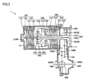
- Fig. 3 is a sectional view of a modification of drive unit 1 of the present embodiment.
- planetary carrier 520 of planetary gear 500 is fixed to case 12 in the present modification, and ring gear 530 is connected to output shaft 320.
- the "reduction mechanism" of rotating electric machine 200 can be obtained by such a configuration.
- drive unit 1 of the present embodiment includes input shaft 310 connected to the engine, a "power conversion unit” with rotating electric machines 100 and 200 and planetary gears 400 and 500 to convert the power applied from input shaft 310, and gears 600 and 700 identified as the power output unit that convey the power output from the power conversion unit to the drive shaft of the vehicle.
- Planetary gears 400 and 500 of the power conversion unit are formed as separate components from gears 600 and 700, and rotating electric machines 100 and 200 of the power conversion unit are stored in a unitary case 12.
- Drive unit 1 further includes an output shaft 320 provided concentric with input shaft 310, and connected to planetary gears 400 and 500 and gear 600. Gears 600 and 700 are provided between the engine and rotating electric machines 110 and 200.
- Rotating electric machine 100 includes a rotation shaft 110 and rotating electric machine 200 includes a rotation shaft 210.
- Input shaft 310 is arranged at the inner circumferential side of rotation shafts 110 and 210.
- Bearings 315B and 325B supporting rotation shafts 110 and 210 are provided between input shaft 310 and rotation shafts 110 and 210.
- Planetary gear 400 constitutes the power split device.
- Planetary gear 500 constitutes the reduction mechanism.
- Planetary gear 400 is connected to rotating electric machine 100, input shaft 310, and gear 600.
- sun gear 410 is formed integrally with rotation shaft 110 of rotating electric machine 100
- planetary carrier 420 is connected to input shaft 310.
- Ring gear 430 is connected to gear 600 via output shaft 320.
- Planetary gear 500 is provided at a power transmission path between rotating electric machine 200 and gear 600.
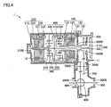
- a drive unit 1 according to a second embodiment of the present invention is a modification of drive unit 1 of the first embodiment.
- Drive unit 1 of the second embodiment is characterized in that each of the components constituting the power conversion unit is arranged in the order of rotating electric machine 200, planetary gear 500, planetary gear 400, and rotating electric machine 100 from the rear side of case 12 (the left side in Fig. 4 ).
- Another feature is that ring gear 430 of planetary gear 400 is connected to input shaft 310, and planetary carrier 420 is connected to output shaft 320.
- sun gear 510 of planetary gear 500 is connected to rotation shaft 210 of rotating electric machine 200
- planetary carrier 520 is connected to output shaft 320 via planetary carrier 420
- Ring gear 530 is fixed to case 12. Accordingly, the reduction mechanism of rotating electric machine 200 can be implemented.
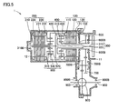
- Fig. 5 is a sectional view of a modification of drive unit 1 of the second embodiment.
- planetary carrier 520 of planetary gear 500 is affixed to case 12.
- Ring gear 530 is connected to output shaft 320 via planetary carrier 420.
- the productivity of drive unit 1 can be improved in accordance with the configuration shown in Figs. 4 and 5 , likewise the first embodiment.
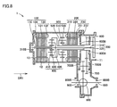
- a drive unit 1 of the third embodiment is a modification of drive unit 1 of the first and second embodiments.
- drive unit 1 of the third embodiment is characterized in that each of components constituting the power conversion unit is arranged in the order of rotating electric machine 100, planetary gear 400, rotating electric machine 200, and planetary gear 500 from the rear side of case 12 (the left side in Fig. 6 ).
- the connection of sun gear 410 of planetary gear 400 to rotation shaft 110 of rotating electric machine 100, the connection of planetary carrier 420 to input shaft 310, and the connection of ring gear 430 to output shaft 320 are similar to the connections in the first embodiment.
- the power split device of distributing the power from input shaft 310 to rotating electric machine 100 and output shaft 320 likewise the first and second embodiments, is implemented.
- Sun gear 510 of planetary gear 500 is connected to rotation shaft 210 of rotating electric machine 200.
- Planetary carrier 520 is connected to output shaft 320.
- Ring gear 530 is affixed to case 12.
- the reduction mechanism of rotating electric machine 200 is implemented.
- Fig. 7 is a sectional view of a modification of drive unit 1 of the third embodiment.
- planetary carrier 520 of planetary gear 500 is affixed to case 12, and ring gear 530 is connected to output shaft 320.
- the reduction mechanism of rotating electric machine 200 can be implemented by such a configuration.
- the productivity of drive unit 1 can be improved in accordance with the configurations of Figs. 6 and 7 , likewise the first and second embodiments.
- drive unit 1 of the fourth embodiment is a modification of drive unit 1 of the first to third embodiments, and is characterized in that a cover 11, a case 12, and a cover 13 constitute the housing. Accordingly, rotating electric machines 100 and 200 can be inserted into case 12 even from the direction indicated by arrow DR1. Rotating electric machines 100 and 200 are formed integrally in unitary case 12 in the present embodiment.
- the productivity of drive unit 1 can be improved in accordance with the configuration of Fig. 8 , likewise the first to third embodiments.
- drive unit 1 of the fifth embodiment is a modification of drive unit 1 of the first to fourth embodiments, and is characterized in that the output from planetary gear 400 identified as the power split device and the output from rotating electric machine 200 are transmitted individually to gears 600 and 700 identified as the power output unit.
- the example of Fig. 9 represents that the output from ring gear 430 in planetary gear 400 is transmitted to gear 600 identified as the power output unit via output shaft 320 whereas the output from rotation shaft 210 of rotating electric machine 200 is transmitted to gear 700 identified as the power output unit via gear 650 constituting the reduction mechanism.
- Fig. 10 is a sectional view of a modification of drive unit 1 of the fifth embodiment.
- the output from rotation shaft 210 of rotating electric machine 200 is transmitted to gear 650 via planetary gear 500.
- gear 500 and gear 650 constituting the reduction mechanism of rotating electric machine 200, a higher reduction gear ratio can be achieved.
- the productivity of drive unit 1 can be improved in accordance with the configurations of Figs. 9 and 10 , likewise the first to fourth embodiments.
- drive unit 1 of the sixth embodiment is a modification of drive unit 1 of the first embodiment, and is characterized in that the shaft support mechanism in the direction of the diameter of the shaft differs from the mechanism in the first embodiment.
- rotation shaft 110 has one end directly supported by case 12 via bearing 110B attached to case 12.
- bearing 110B is provided between rotation shaft 110 and case 12.
- rotation shaft 210 is directly supported by case 12 via bearings 210B1 and 210B2 attached to case 12.
- bearings 210B1 and 210B2 are provided between rotation shaft 210 and case 12.
- the centrifugal force by the rotation of rotors 130 and 230 and the weight of rotors 130 and 230 act on input shaft 310 as external force.
- the external force from rotors 130 and 230 becomes greater in proportion to a higher rotational speed of rotors 130 and 230. If the diameter of input shaft 310 is increased in order to ensure the strength of input shaft 310, the outer diameter of the planetary gear and/or rotation sensor will also become greater to become a factor in increasing the size of drive unit 1. Restricting the rotational speed of rotors 130 and 230, however, may induce power-down.
- a rotating electric machine having an output greater than that of rotating electric machine 100 that generates power mainly based on the motive power from the engine is employed as rotating electric machine 200 that generates the motive power to drive the vehicle. Therefore, the employed rotating electric machine 200 is larger than rotating electric machine 100 (for example, longer axial length (L2 > L1) when of the same diameter as shown in Fig. 11 ). This means that the vibration of rotating electric machine 200 tends to become greater than the vibration of rotating electric machine 100. Therefore, it is particularly important to reduce the external force acting on input shaft 310 from rotor 230.
- the present embodiment has the external force acting on input shaft 310 from rotation shaft 210 reduced by directly supporting rotation shaft 210 on case 12 via bearings 210B1 and 210B2. Therefore, the maximum rotational speed of rotating electric machine 200 can be increased while suppressing excessive increase in the diameter of input shaft 310.
- Rotation shaft 110 has only one end directly supported by case 12.
- the other end of rotation shaft 110 is supported indirectly by case 12 via input shaft 310 and the like.
- input shaft 310 input shaft 310 and the like.
- bearing 210B1 is provided at a projection 12A protruding from the inner wall of case 12 at a region between rotating electric machines 100 and 200. Provision of such a projection 12A is advantageous in that the rigidity of case 12 is improved and the noise during the drive of drive unit 1 is reduced.
- ring gear 530 is affixed to projection 12A. This is advantageous in that the noise in drive unit 1 during operation thereof is further reduced.
- rotation shafts 110 and 210 are both supported by case 12 in the example of Fig. 11 , only one of rotation shafts 110 and 210 may be supported by case 12.
- the present invention is applicable to a power transmission apparatus of a hybrid vehicle.
Abstract
Claims (12)
- Appareil de transmission de puissance d'un véhicule hybride comportant :un arbre d'entrée (310) relié à un moteur à combustion interne,une unité de conversion de puissance (100, 200, 400) comprenant des première et deuxième machines électriques tournantes (100, 200) alignées dans une direction axiale et un engrenage planétaire (400) afin de convertir de la puissance appliquée à partir dudit arbre d'entrée (310), etune unité de sortie de puissance (600, 700) transmettant une sortie de puissance depuis ladite unité de conversion de puissance (100, 200, 400) jusqu'à un arbre d'entraînement du véhicule, dans lequelladite unité de conversion de puissance (100, 200, 400) est formée séparément de ladite unité de sortie de puissance (600, 700),lesdites première et deuxième machines électriques tournantes (100, 200) de ladite unité de conversion de puissance (100, 200, 400) sont logées dans un carter unitaire (12),lesdites première et deuxième machines électriques tournantes (100, 200) peuvent toutes les deux être insérées dans ledit carter (12) depuis une direction à l'écart dudit moteur à combustion interne,ladite première machine électrique tournante (100) comprend un premier arbre de rotation (110),ladite deuxième machine électrique tournante (200) comprend un deuxième arbre de rotation (210),ledit arbre d'entrée (310) est disposé sur un côté circonférentiel intérieur desdits premier et deuxième arbres de rotation (110, 210),caractérisé en ce qu'un palier (315B) supportant ledit premier arbre de rotation (110) et un arbre de sortie (320) est prévu entre une face circonférentielle extérieure dudit arbre d'entrée (310) et une face circonférentielle intérieure dudit premier arbre de rotation (110) et dudit arbre de sortie (320), respectivement,un palier (325B) supportant ledit deuxième arbre de rotation (210) est prévu entre une face circonférentielle extérieure dudit arbre de sortie (320) et une face circonférentielle intérieure dudit deuxième arbre de rotation (210),lesdits premier et deuxième arbres de rotation (110, 210) sont supportés, dans la direction de leur diamètre, sur ledit carter (12) par l'intermédiaire dudit arbre d'entrée (310).
- Appareil de transmission de puissance d'un véhicule hybride selon la revendication 1, dans lequel ladite unité de sortie de puissance (600, 700) est disposée entre ledit moteur à combustion interne et ladite unité de conversion de puissance (100, 200, 400).
- Appareil de transmission de puissance d'un véhicule hybride selon la revendication 1, comportant en outre un autre palier (110B, 210B1, 210B2) fourni entre ledit carter (12) et au moins un desdits premier et deuxième arbres de rotation (110, 210).
- Appareil de transmission de puissance d'un véhicule hybride selon la revendication 3, dans lequel ledit carter (12) comprend une saillie (12A) dépassant d'une paroi intérieure dudit carter (12) dans un emplacement entre lesdites première et deuxième machines électriques tournantes (100, 200), et
Ledit autre palier (210B) est prévu au niveau de ladite saillie (12A). - Appareil de transmission de puissance d'un véhicule hybride selon la revendication 1, dans lequel
lesdits premier et deuxième arbres de rotation (110, 210) ont une configuration droite, et
lesdits premier et deuxième arbres de rotation (110, 210) et rotors (120, 220) desdites première et deuxième machines électriques tournantes (100, 200) sont montés avec cannelure, respectivement. - Appareil de transmission de puissance d'un véhicule hybride selon la revendication 1, dans lequel
ladite unité de conversion de puissance comprend un dispositif de séparation de puissance (400) comprenant ledit engrenage planétaire (400), et un mécanisme de réduction (500, 650),
ledit engrenage planétaire (400) étant relié audit arbre d'entrée (310), à ladite première machine électrique tournante (100), et à ladite unité de sortie de puissance (600, 700),
ledit mécanisme de réduction (500, 650) étant prévu dans un passage de transmission de puissance entre ladite deuxième machine électrique tournante (200) et ladite unité de sortie de puissance (600, 700). - Appareil de transmission de puissance d'un véhicule hybride selon la revendication 6, dans lequel un porte-planétaire (420) dudit engrenage planétaire (400) dans ledit dispositif de division de puissance (400) est relié audit arbre d'entrée (310), et
une couronne dentée (430) dudit engrenage planétaire (400) est reliée à ladite unité de sortie de puissance (600, 700). - Appareil de transmission de puissance d'un véhicule hybride selon la revendication 6, dans lequel une couronne dentée (430) dudit engrenage planétaire (400) dans ledit dispositif de division de puissance (400) est reliée audit arbre d'entrée (310), et
un porte-planétaire (420) dudit engrenage planétaire (400) est relié à ladite unité de sortie de puissance (600, 700). - Appareil de transmission de puissance d'un véhicule hybride selon la revendication 6, dans lequel le ledit mécanisme de réduction comprend un autre engrenage planétaire (500),
ledit autre engrenage planétaire (500) étant fixé sur ledit carter (12) dans une zone centrale axiale de ladite unité de conversion de puissance (100, 200, 400). - Appareil de transmission de puissance d'un véhicule hybride selon la revendication 6, dans lequel le ledit mécanisme de réduction comprend un autre engrenage planétaire (500),
une couronne dentée (530) dudit autre engrenage planétaire (500) étant fixée sur ledit carter (12). - Appareil de transmission de puissance d'un véhicule hybride selon la revendication 6, dans lequel une sortie dudit dispositif de division de puissance (400) et une sortie dudit mécanisme de réduction (650) sont transmises individuellement à ladite unité de sortie de puissance (600, 700).
- Appareil de transmission de puissance d'un véhicule hybride selon la revendication 1, ledit arbre de sortie (320) étant relié audit engrenage planétaire (400) et à ladite unité de sortie de puissance (600, 700), et prévu de manière concentrique audit arbre d'entrée (310).
Applications Claiming Priority (3)
| Application Number | Priority Date | Filing Date | Title |
|---|---|---|---|
| JP2005186596 | 2005-06-27 | ||
| JP2005294929A JP4337800B2 (ja) | 2005-06-27 | 2005-10-07 | ハイブリッド車両の動力伝達装置 |
| PCT/JP2006/307994 WO2007000848A1 (fr) | 2005-06-27 | 2006-04-10 | Appareil de transmission de puissance de véhicule hybride |
Publications (2)
| Publication Number | Publication Date |
|---|---|
| EP1896283A1 EP1896283A1 (fr) | 2008-03-12 |
| EP1896283B1 true EP1896283B1 (fr) | 2011-08-17 |
Family
ID=36585490
Family Applications (1)
| Application Number | Title | Priority Date | Filing Date |
|---|---|---|---|
| EP06731930A Expired - Fee Related EP1896283B1 (fr) | 2005-06-27 | 2006-04-10 | Appareil de transmission de puissance de vehicule hybride |
Country Status (4)
| Country | Link |
|---|---|
| US (1) | US8142317B2 (fr) |
| EP (1) | EP1896283B1 (fr) |
| JP (1) | JP4337800B2 (fr) |
| WO (1) | WO2007000848A1 (fr) |
Families Citing this family (21)
| Publication number | Priority date | Publication date | Assignee | Title |
|---|---|---|---|---|
| WO2008085931A2 (fr) * | 2007-01-09 | 2008-07-17 | Magnetic Torque International, Ltd. | Système d'engrenages planétaires magnétique et dispositif l'utilisant |
| FR2912694B1 (fr) * | 2007-02-21 | 2009-04-10 | Renault Soc Par Actions Simpli | Transmission a derivation de puissance a machine electrique independante. |
| JP2009107491A (ja) * | 2007-10-30 | 2009-05-21 | Aisin Aw Co Ltd | 車両用駆動装置 |
| CN101280722B (zh) * | 2008-06-03 | 2010-10-06 | 赵清涛 | 一种多能源直轴混合动力发动机 |
| US8523734B2 (en) | 2008-11-07 | 2013-09-03 | Ricardo, Inc. | Multi-mode hybrid transmission |
| WO2010151579A1 (fr) * | 2009-06-23 | 2010-12-29 | Fisker Automotive, Inc. | Configurations d'entraînement pour systèmes d'entraînement à moteur à haute vitesse |
| CN102459957B (zh) | 2009-06-24 | 2015-05-06 | 菲斯科汽车科技集团有限公司 | 用于高混合动力串联/并联高速电机驱动系统的驱动配置 |
| JP5333343B2 (ja) * | 2010-05-13 | 2013-11-06 | 三菱自動車工業株式会社 | 左右輪駆動装置 |
| KR101131246B1 (ko) | 2010-06-22 | 2012-03-30 | 주식회사 만도 | 입력전압제어방법 및 장치와, 차량용 전자제어장치 |
| DE102011016727A1 (de) * | 2011-04-11 | 2012-10-11 | Magna Powertrain Ag & Co. Kg | Getriebeeinheit |
| JP5638050B2 (ja) * | 2012-10-05 | 2014-12-10 | 本田技研工業株式会社 | 車両用駆動装置 |
| CN102996767A (zh) * | 2012-12-21 | 2013-03-27 | 江苏泰来减速机有限公司 | 一种减速机虎头架 |
| TWI535622B (zh) | 2013-01-25 | 2016-06-01 | li-he Yao | Bicycle electric device |
| KR101509704B1 (ko) * | 2013-10-28 | 2015-04-07 | 현대자동차 주식회사 | 하이브리드 차량의 동력전달장치 |
| CA2937868C (fr) * | 2014-01-31 | 2017-11-07 | Honda Motor Co., Ltd. | Moteur |
| CN104191951A (zh) * | 2014-08-29 | 2014-12-10 | 天津市松正电动汽车技术股份有限公司 | 混合动力车辆用电驱动装置 |
| US9643481B2 (en) | 2015-05-20 | 2017-05-09 | Ford Global Technologies, Llc | Multi-mode powersplit hybrid transmission |
| US9694663B2 (en) | 2015-07-24 | 2017-07-04 | Ford Global Technologies, Llc | Hybrid transmission |
| US10082196B2 (en) | 2016-09-01 | 2018-09-25 | Ford Global Technologies, Llc | Hybrid transaxle |
| US10017045B1 (en) * | 2017-01-05 | 2018-07-10 | GM Global Technology Operations LLC | Transmission for a hybrid powertrain |
| CN113726116B (zh) * | 2021-08-18 | 2022-11-29 | 潍柴动力股份有限公司 | 一种电机及车辆 |
Family Cites Families (21)
| Publication number | Priority date | Publication date | Assignee | Title |
|---|---|---|---|---|
| JPH08318746A (ja) | 1995-05-25 | 1996-12-03 | Aqueous Res:Kk | ハイブリット車輌 |
| JPH09132042A (ja) * | 1995-11-06 | 1997-05-20 | Denso Corp | 車両用動力伝達装置 |
| JP3216589B2 (ja) * | 1996-10-29 | 2001-10-09 | トヨタ自動車株式会社 | 動力出力装置,原動機制御装置並びにこれらの制御方法 |
| US5935035A (en) * | 1998-06-24 | 1999-08-10 | General Motors Corporation | Electro-mechanical powertrain |
| US5931757A (en) * | 1998-06-24 | 1999-08-03 | General Motors Corporation | Two-mode, compound-split electro-mechanical vehicular transmission |
| US6022287A (en) * | 1998-08-19 | 2000-02-08 | General Motors Corporation | Modularly constructed vehicular transmission |
| WO2000032433A1 (fr) | 1998-12-01 | 2000-06-08 | Hitachi, Ltd. | Dispositif d'entrainement et vehicule |
| JP3674402B2 (ja) * | 1999-08-18 | 2005-07-20 | 日産自動車株式会社 | 車両の駆動装置 |
| JP2001138752A (ja) * | 1999-11-12 | 2001-05-22 | Nissan Motor Co Ltd | シリーズ式ハイブリッド車両の動力装置 |
| JP3909644B2 (ja) | 1999-12-27 | 2007-04-25 | アイシン・エィ・ダブリュ株式会社 | ハイブリッド駆動装置 |
| JP4636651B2 (ja) * | 2000-04-07 | 2011-02-23 | Gknドライブラインジャパン株式会社 | 動力伝達装置 |
| JP3893960B2 (ja) | 2001-01-12 | 2007-03-14 | トヨタ自動車株式会社 | 動力伝達装置 |
| ITBO20010734A1 (it) * | 2001-11-30 | 2003-05-30 | New Holland Italia Spa | Gruppo di propulsione ibrido per trattori agricoli |
| JP3699694B2 (ja) * | 2002-05-31 | 2005-09-28 | 日産自動車株式会社 | ハイブリッド変速機 |
| JP3650089B2 (ja) | 2002-08-02 | 2005-05-18 | トヨタ自動車株式会社 | ハイブリッド駆動装置並びにそれを搭載した自動車 |
| JP2004204995A (ja) * | 2002-12-26 | 2004-07-22 | Nissan Motor Co Ltd | ハイブリッド駆動装置とその組み付け方法 |
| JP2004340010A (ja) | 2003-05-15 | 2004-12-02 | Toyota Motor Corp | 車両のエンジン始動装置 |
| KR100815528B1 (ko) * | 2003-06-30 | 2008-10-27 | 도요타지도샤가부시키가이샤 | 하이브리드 구동장치 및 이를 탑재한 자동차 |
| JP3864950B2 (ja) | 2003-11-18 | 2007-01-10 | 日産自動車株式会社 | ハイブリッド変速機 |
| JP3986494B2 (ja) * | 2003-12-02 | 2007-10-03 | アイシン・エィ・ダブリュ株式会社 | ハイブリッド駆動装置、及びハイブリッド駆動装置を搭載した自動車 |
| JP4406883B2 (ja) * | 2005-03-25 | 2010-02-03 | スズキ株式会社 | ハイブリッド車両の駆動装置 |
-
2005
- 2005-10-07 JP JP2005294929A patent/JP4337800B2/ja not_active Expired - Fee Related
-
2006
- 2006-04-10 WO PCT/JP2006/307994 patent/WO2007000848A1/fr active Application Filing
- 2006-04-10 EP EP06731930A patent/EP1896283B1/fr not_active Expired - Fee Related
- 2006-04-10 US US11/921,792 patent/US8142317B2/en not_active Expired - Fee Related
Also Published As
| Publication number | Publication date |
|---|---|
| EP1896283A1 (fr) | 2008-03-12 |
| WO2007000848A1 (fr) | 2007-01-04 |
| US8142317B2 (en) | 2012-03-27 |
| JP4337800B2 (ja) | 2009-09-30 |
| JP2007039000A (ja) | 2007-02-15 |
| US20100041502A1 (en) | 2010-02-18 |
Similar Documents
| Publication | Publication Date | Title |
|---|---|---|
| EP1896283B1 (fr) | Appareil de transmission de puissance de vehicule hybride | |
| EP1717086B2 (fr) | Moteur électrique avec un engrenage planétaire | |
| US7975571B2 (en) | Hybrid drive device | |
| EP1918150B1 (fr) | Appareil de contrôle pour véhicule hybride | |
| US8641568B2 (en) | Electric machine for an electric axle of a motor vehicle | |
| US6328123B1 (en) | Electrical drive for a wheel hub | |
| CN100581863C (zh) | 混合动力车辆的动力传递装置 | |
| US6533696B1 (en) | Vehicle drive unit | |
| JP4352269B2 (ja) | ハイブリッド駆動装置 | |
| JP5123015B2 (ja) | 発電電動機 | |
| JP2006300101A (ja) | 回転電機の潤滑装置 | |
| JP6209127B2 (ja) | モータ構造体 | |
| JP6596897B2 (ja) | モータ駆動装置 | |
| JP4427700B2 (ja) | ハイブリッド駆動装置 | |
| JP2010162930A (ja) | モータ動力出力装置、及び、これを含むハイブリッド駆動装置 | |
| JP5430517B2 (ja) | 車両の駆動装置 | |
| EP1419921B1 (fr) | Transmission hybride | |
| EP3968500A1 (fr) | Machine dynamoélectrique | |
| CN110912337A (zh) | 一种内置行星排减速单元的车用驱动电机 | |
| CN214057235U (zh) | 一种差速器与直驱电机一体的后桥总成 | |
| JP2010273504A (ja) | ロータ、回転電機および車両 | |
| US11752856B2 (en) | Driving apparatus | |
| CN112356663A (zh) | 一种差速器与直驱电机一体的后桥总成 | |
| CN116783800A (zh) | 电机装置及车辆车轴 |
Legal Events
| Date | Code | Title | Description |
|---|---|---|---|
| PUAI | Public reference made under article 153(3) epc to a published international application that has entered the european phase |
Free format text: ORIGINAL CODE: 0009012 |
|
| 17P | Request for examination filed |
Effective date: 20071228 |
|
| AK | Designated contracting states |
Kind code of ref document: A1 Designated state(s): DE FR GB |
|
| RBV | Designated contracting states (corrected) |
Designated state(s): DE FR GB |
|
| DAX | Request for extension of the european patent (deleted) | ||
| 17Q | First examination report despatched |
Effective date: 20090323 |
|
| GRAJ | Information related to disapproval of communication of intention to grant by the applicant or resumption of examination proceedings by the epo deleted |
Free format text: ORIGINAL CODE: EPIDOSDIGR1 |
|
| GRAP | Despatch of communication of intention to grant a patent |
Free format text: ORIGINAL CODE: EPIDOSNIGR1 |
|
| GRAS | Grant fee paid |
Free format text: ORIGINAL CODE: EPIDOSNIGR3 |
|
| GRAA | (expected) grant |
Free format text: ORIGINAL CODE: 0009210 |
|
| AK | Designated contracting states |
Kind code of ref document: B1 Designated state(s): DE FR GB |
|
| REG | Reference to a national code |
Ref country code: GB Ref legal event code: FG4D |
|
| REG | Reference to a national code |
Ref country code: DE Ref legal event code: R096 Ref document number: 602006023836 Country of ref document: DE Effective date: 20111013 |
|
| PLBE | No opposition filed within time limit |
Free format text: ORIGINAL CODE: 0009261 |
|
| STAA | Information on the status of an ep patent application or granted ep patent |
Free format text: STATUS: NO OPPOSITION FILED WITHIN TIME LIMIT |
|
| 26N | No opposition filed |
Effective date: 20120521 |
|
| PGFP | Annual fee paid to national office [announced via postgrant information from national office to epo] |
Ref country code: DE Payment date: 20120425 Year of fee payment: 7 |
|
| PGFP | Annual fee paid to national office [announced via postgrant information from national office to epo] |
Ref country code: GB Payment date: 20120404 Year of fee payment: 7 Ref country code: FR Payment date: 20120504 Year of fee payment: 7 |
|
| REG | Reference to a national code |
Ref country code: DE Ref legal event code: R097 Ref document number: 602006023836 Country of ref document: DE Effective date: 20120521 |
|
| GBPC | Gb: european patent ceased through non-payment of renewal fee |
Effective date: 20130410 |
|
| PG25 | Lapsed in a contracting state [announced via postgrant information from national office to epo] |
Ref country code: GB Free format text: LAPSE BECAUSE OF NON-PAYMENT OF DUE FEES Effective date: 20130410 Ref country code: DE Free format text: LAPSE BECAUSE OF NON-PAYMENT OF DUE FEES Effective date: 20131101 |
|
| REG | Reference to a national code |
Ref country code: FR Ref legal event code: ST Effective date: 20131231 |
|
| REG | Reference to a national code |
Ref country code: DE Ref legal event code: R119 Ref document number: 602006023836 Country of ref document: DE Effective date: 20131101 |
|
| PG25 | Lapsed in a contracting state [announced via postgrant information from national office to epo] |
Ref country code: FR Free format text: LAPSE BECAUSE OF NON-PAYMENT OF DUE FEES Effective date: 20130430 |