EP1892166A2 - Luftzufuhrsystem mit reduziertem Ölfluss in den Verdichter - Google Patents
Luftzufuhrsystem mit reduziertem Ölfluss in den Verdichter Download PDFInfo
- Publication number
- EP1892166A2 EP1892166A2 EP07015840A EP07015840A EP1892166A2 EP 1892166 A2 EP1892166 A2 EP 1892166A2 EP 07015840 A EP07015840 A EP 07015840A EP 07015840 A EP07015840 A EP 07015840A EP 1892166 A2 EP1892166 A2 EP 1892166A2
- Authority
- EP
- European Patent Office
- Prior art keywords
- air
- port
- compressor
- isolation valve
- inlet port
- Prior art date
- Legal status (The legal status is an assumption and is not a legal conclusion. Google has not performed a legal analysis and makes no representation as to the accuracy of the status listed.)
- Withdrawn
Links
Images

Classifications
-
- B—PERFORMING OPERATIONS; TRANSPORTING
- B60—VEHICLES IN GENERAL
- B60T—VEHICLE BRAKE CONTROL SYSTEMS OR PARTS THEREOF; BRAKE CONTROL SYSTEMS OR PARTS THEREOF, IN GENERAL; ARRANGEMENT OF BRAKING ELEMENTS ON VEHICLES IN GENERAL; PORTABLE DEVICES FOR PREVENTING UNWANTED MOVEMENT OF VEHICLES; VEHICLE MODIFICATIONS TO FACILITATE COOLING OF BRAKES
- B60T17/00—Component parts, details, or accessories of power brake systems not covered by groups B60T8/00, B60T13/00 or B60T15/00, or presenting other characteristic features
- B60T17/04—Arrangements of piping, valves in the piping, e.g. cut-off valves, couplings or air hoses
-
- F—MECHANICAL ENGINEERING; LIGHTING; HEATING; WEAPONS; BLASTING
- F15—FLUID-PRESSURE ACTUATORS; HYDRAULICS OR PNEUMATICS IN GENERAL
- F15B—SYSTEMS ACTING BY MEANS OF FLUIDS IN GENERAL; FLUID-PRESSURE ACTUATORS, e.g. SERVOMOTORS; DETAILS OF FLUID-PRESSURE SYSTEMS, NOT OTHERWISE PROVIDED FOR
- F15B11/00—Servomotor systems without provision for follow-up action; Circuits therefor
- F15B11/06—Servomotor systems without provision for follow-up action; Circuits therefor involving features specific to the use of a compressible medium, e.g. air, steam
-
- B—PERFORMING OPERATIONS; TRANSPORTING
- B60—VEHICLES IN GENERAL
- B60T—VEHICLE BRAKE CONTROL SYSTEMS OR PARTS THEREOF; BRAKE CONTROL SYSTEMS OR PARTS THEREOF, IN GENERAL; ARRANGEMENT OF BRAKING ELEMENTS ON VEHICLES IN GENERAL; PORTABLE DEVICES FOR PREVENTING UNWANTED MOVEMENT OF VEHICLES; VEHICLE MODIFICATIONS TO FACILITATE COOLING OF BRAKES
- B60T17/00—Component parts, details, or accessories of power brake systems not covered by groups B60T8/00, B60T13/00 or B60T15/00, or presenting other characteristic features
- B60T17/02—Arrangements of pumps or compressors, or control devices therefor
-
- F—MECHANICAL ENGINEERING; LIGHTING; HEATING; WEAPONS; BLASTING
- F15—FLUID-PRESSURE ACTUATORS; HYDRAULICS OR PNEUMATICS IN GENERAL
- F15B—SYSTEMS ACTING BY MEANS OF FLUIDS IN GENERAL; FLUID-PRESSURE ACTUATORS, e.g. SERVOMOTORS; DETAILS OF FLUID-PRESSURE SYSTEMS, NOT OTHERWISE PROVIDED FOR
- F15B11/00—Servomotor systems without provision for follow-up action; Circuits therefor
Definitions
- the present invention relates generally to air supply systems using reciprocating type air compressors and, more particularly, to compressor unloading systems usable in such air supply systems, such as might be found in air supply systems for truck air brakes and the like.
- Air compressors used in medium and heavy duty vehicle air supply systems such as those found in transport trucks, passenger buses, and the like, generally involve having an air compressor directly driven by the vehicle engine and supplied with inlet air at atmospheric pressure, or, in the case of many transport trucks today, turbocharged air from the engine turbocharger via the engine air intake manifold.
- a clutched compressor was developed, but was not felt to be the answer to the horsepower loss problem because the compressor shaft normally runs through the compressor and often drives other accessories, such as the power steering, or engine fuel pump, and it was not satisfactory to have the power steering and other items nonfunctional for the time the compressor was unloaded. Also, the clutched compressor would substantially increase the cost of the air supply system, and this was not satisfactory. Thus, not much progress was made in developing a more efficient compressor unloading system, and simply holding the intake valve open to allow unloading either to atmosphere, or the engine turbocharger, was the accepted way of unloading the air compressor for some time.
- Another object of the present invention is to provide an air supply system having the above characteristics and which reduces the horsepower used by air compressors in their unloaded mode as compared to traditional systems.
- a further object of the present invention is to provide an air supply system having the above characteristics and which is automatically actuated in the unloading mode.
- Still another object of the present invention is to provide an air supply system having the above characteristics and which causes relatively equalized pressure to be maintained on both sides of the compressor pistons.
- Yet a further object of the present invention is to provide an air supply system having the above characteristics and which results in reduced levels of oil passing around the compressor piston rings when the compressor is in its unloading mode.
- an air supply system including a compressor having a compression chamber, an inlet port through which air flows into the compression chamber and an outlet port through which air exits the compression chamber, an unloader which causes the compressor to be in an unloaded state in response to a pneumatic signal received at a signal port, and an isolation valve.
- the isolation valve has an inlet port, an outlet port and a signal port, the inlet port of the isolation valve being in fluid communication with a source of inlet air, and the outlet port of the isolation valve being in fluid communication with the inlet port of the compressor.
- the isolation valve allows air to flow from the inlet port of the isolation valve to the outlet port of the isolation valve, and thereby allows air to flow from the source of inlet air to the inlet port of the compressor, when no pneumatic signal is received at the signal port of the isolation valve, and prevents air from flowing from the inlet port of the isolation valve to the outlet port of the isolation valve, and thereby prevents air from flowing from the source of inlet air to the inlet port of the compressor, when a pneumatic signal is received at the signal port of the isolation valve.
- the air supply system also includes a governor having an unloading port in fluid communication with the signal port of the isolation valve and with the signal port of the unloader, the governor supplying a pneumatic signal to the signal port of the isolation valve and the signal port of the unloader when a desired system air pressure is maintained, and a source of pressurized air supplying pressurized air to the inlet port of the compressor at least when the pneumatic signal is received by the isolation valve.
- the pressurized air supplied by the source of pressurized air to the inlet port of the compressor has a pressure about equal to a pressure of air in the crankcase of the compressor.
- the source of pressurized air comprises an air reservoir in fluid communication with the inlet port of the compressor.
- the air supply system further includes a pressure regulator in fluid communication between the air reservoir and the inlet port of the compressor, the pressure regulator regulating a pressure of air supplied by the reservoir such that the pressurized air supplied by the reservoir to the inlet port of the compressor has a pressure about equal to a pressure of air a in the crankcase of the compressor.
- the unloading port of the governor is in fluid communication with the inlet port of the compressor, such that the source of pressurized air comprises the unloading port of the governor.
- the air supply system further includes a pressure regulator in fluid communication between the unloading port of the governor and the inlet port of the compressor, the pressure regulator regulating a pressure of air supplied by the unloading port of the governor such that the pressurized air supplied by the unloading port of the governor to the inlet port of the compressor has a pressure about equal to a pressure of air in the crankcase of the compressor.
- the governor further comprises a reservoir port, and the air supply system further includes a reservoir having a port in fluid communication with the reservoir port of the governor.
- the isolation valve comprises a valve body moveable, in response to the pneumatic signal received at the signal port of the isolation valve, between an open position in which the isolation valve allows air to flow from the inlet port of the isolation valve to the outlet port of the isolation valve, and thereby allows air to flow from the source of inlet air to the inlet port of the compressor, and a closed position in which the isolation valve prevents air from flowing from the inlet port of the isolation valve to the outlet port of the isolation valve, and-thereby prevents air from flowing from the source of inlet air to the inlet port of the compressor.
- the valve body is biased toward the open position, and is moveable against the bias to the closed position when the pneumatic signal is received at the signal port of the isolation valve.
- an air supply system includes a compressor having a compression chamber, an inlet port through which air flows into the compression chamber and an outlet port through which air exits the compression chamber, an unloader which causes the compressor to be in an unloaded state when a desired system air pressure is maintained, an isolation valve preventing inlet air from flowing into the inlet port of the compressor when the compressor is in the unloaded state, and a source of pressurized air supplying pressurized air to the inlet port of the compressor at least when the isolation valve prevents inlet air from flowing into the inlet port of the compressor.
- the pressurized air supplied by the source of pressurized air to the inlet port of the compressor has a pressure about equal to a pressure of air in the crankcase of the compressor.
- the source of pressurized air comprises an air reservoir in fluid communication with the inlet port of the compressor.
- the air supply system further includes a pressure regulator in fluid communication between the air reservoir and the inlet port of the compressor, the pressure regulator regulating a pressure of air supplied by the reservoir such that the pressurized air supplied by the reservoir to the inlet port of the compressor has a pressure about equal to a pressure of air in the crankcase of the compressor.
- the air supply system further includes a governor in fluid communication with the isolation valve and with the unloader, the governor signaling the unloader to cause the compressor to be in the unloaded state when the desired system air pressure is maintained, and signaling the isolation valve to prevent inlet air from flowing into the inlet port of the compressor when the desired system air pressure is maintained.
- the governor is in fluid communication with the inlet port of the compressor, such that the source of pressurized air comprises the governor.
- the air supply system further includes a pressure regulator in fluid communication between the governor and the inlet port of the compressor, the pressure regulator regulating a pressure of air supplied by the governor such that the pressurized air supplied by the governor to the inlet port of the compressor has a pressure about equal to a pressure of air in the crankcase of the compressor.
- the air supply system further includes a reservoir in fluid communication with the governor.
- an air supply system includes a compressor having a compression chamber, an inlet port through which air flows into the compression chamber and an outlet port through which air exits the compression chamber, an unloader which causes the compressor to be in an unloaded state in response to a pneumatic signal received at a signal port, and an isolation valve.
- the isolation valve has an inlet port, an outlet port and a signal port, the inlet port of the isolation valve being in fluid communication with a source of inlet air, and the outlet port of the isolation valve being in fluid communication with the inlet port of the compressor.
- the isolation valve also includes a valve body moveable between an open position in which the isolation valve allows air to flow from the inlet port of the isolation valve to the outlet port of the isolation valve, and thereby allows air to flow from the source of inlet air to the inlet port of the compressor, and a closed position in which the isolation valve prevents air from flowing from the inlet port of the isolation valve to the outlet port of the isolation valve, and thereby prevents air from flowing from the source of inlet air to the inlet port of the compressor.
- the valve body is biased toward the open position, and is moveable against the bias to the closed position when a pneumatic signal is received at the signal port of the isolation valve.
- the air supply system further includes a governor having an unloading port in fluid communication with the signal port of the isolation valve and with the signal port of the unloader, the governor supplying a pneumatic signal to the signal port of the isolation valve and the signal port of the unloader when a desired system air pressure is maintained.
- the air supply system includes an air reservoir in fluid communication with the inlet port of the compressor, the air reservoir supplying pressurized air to the inlet port of the compressor at least when the pneumatic signal is received by the isolation valve.
- the air supply system further includes a pressure regulator in fluid communication between the air reservoir and the inlet port of the compressor, the pressure regulator regulating a pressure of air supplied by the reservoir such that the pressurized air supplied by the reservoir to the inlet port of the compressor has a pressure about equal to a pressure of air in the crankcase of the compressor.
- an air supply system includes a compressor having a compression chamber, an inlet port through which air flows into the compression chamber and an outlet port through which air exits the compression chamber, an unloader which causes the compressor to be in an unloaded state in response to a pneumatic signal received at a signal port, and an isolation valve.
- the isolation valve has an inlet port, an outlet port and a signal port, the inlet port of the isolation valve being in fluid communication with a source of inlet air, and the outlet port of the isolation valve being in fluid communication with the inlet port of the compressor.
- the isolation valve further includes a valve body moveable between an open position in which the isolation valve allows air to flow from the inlet port of the isolation valve to the outlet port of the isolation valve, and thereby allows air to flow from the source of inlet air to the inlet port of the compressor, and a closed position in which the isolation valve prevents air from flowing from the inlet port of the isolation valve to the outlet port of the isolation valve, and thereby prevents air from flowing from the source of inlet air to the inlet port of the compressor.
- the valve body is biased toward the open position, and is moveable against the bias to the closed position when a pneumatic signal is received at the signal port of the isolation valve.
- the air supply system also includes a governor having an unloading port in fluid communication with the signal port of the isolation valve and with the signal port of the unloader, the governor supplying a pneumatic signal to the signal port of the isolation valve and the signal port of the unloader when a desired system air pressure is maintained.
- the unloading port of the governor is in fluid communication with the inlet port of the compressor, such that the unloading port of the governor supplies pressurized air to the inlet port of the compressor at least when the desired system air pressure is maintained.
- the air supply system further includes a pressure regulator in fluid communication between the unloading port of the governor and the inlet port of the compressor, the pressure regulator regulating a pressure of air supplied by the unloading port of the governor such that the pressurized air supplied by the unloading port of the governor to the inlet port of the compressor has a pressure about equal to a pressure of air in the crankcase of the compressor.
- the governor further comprises a reservoir port, and the air supply system further includes a reservoir having a port in fluid communication with the reservoir port of the governor.
- Fig. 1 is a schematic view of an air supply system in accordance with an embodiment of the present invention.
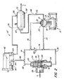
- Fig. 2 is a schematic view of an air supply system in accordance with another embodiment of the present invention.
- Air supply system 10 includes a compressor 12 having a compression chamber 14, a compressor head 15, an inlet port 16 through which air flows into compression chamber 14 and an outlet port 18 through which air exits compression chamber 14.
- Compressor 12 is typically a reciprocating type compressor, and may have any of numerous known or yet to be developed configurations, the particular configuration thereof being generally unimportant to operation of the invention disclosed herein. Since numerous such compressors are extremely well-known in the art, the particular structure and operation of compressor 12 is not discussed herein in detail.
- Unloader 20 causes compressor 12 to be in an unloaded state in response to a pneumatic signal being received at a signal port 22 thereof.
- Unloader 20 may be integrally formed as part of compressor 12 (as shown in the Figures), or may comprise a separate component. Again, since numerous such unloaders are extremely well-known in the art, the particular structure and operation of unloader 20 is not discussed herein in detail.
- Air supply system 10 also includes an isolation valve 24 having an inlet port 26, an outlet port 28 and a signal port 30.
- Inlet port 26 of isolation valve 24 is in fluid communication with a source of inlet air (indicated by arrow A).
- Source of inlet air may simply be the atmosphere, or may be a turbocharger supplying air under pressure.
- An air filter or the like (not shown), or some other component or components may be provided if desired, without affecting the operation of the present invention.
- Outlet port 28 of isolation valve 24 is in fluid communication with inlet port 16 of compressor 12 via conduits 32, 34.
- Isolation valve 24 allows air to flow from inlet port 26 of isolation valve 24 to outlet port 28 of isolation valve 24, and thereby allows air to flow from source of inlet air A to inlet port 16 of compressor 12, when no pneumatic signal is received at signal port 30 of isolation valve 24, and prevents air from flowing from inlet port 26 of isolation valve 24 to outlet port 28 of isolation valve 24, and thereby prevents air from flowing from source of inlet air A to inlet port 16 of compressor 12, when a pneumatic signal is received at signal port 30 of isolation valve 24.
- isolation valve 24 comprises a valve body 36 moveable, in response to a pneumatic signal being received at signal port 30 of isolation valve 24, between an open position (shown in the Figures) in which isolation valve 24 allows air to flow from inlet port 26 of isolation valve 24 to outlet port 28 of isolation valve 24 (indicated by arrow B), and thereby allows air to flow from source of inlet air A to inlet port 16 of compressor 12 via isolation valve 24 and conduits 32, 34, and a closed position (when valve body is moved downward with respect to the orientation shown in the Figures such that valve body 36 seals against valve seat 38) in which isolation valve 24 prevents air from flowing from inlet port 26 of isolation valve 24 to outlet port 28 of isolation valve 24, and thereby prevents air from flowing from source of inlet air (A) to inlet port 16 of compressor 12.
- valve body 36 is biased toward the open position by a spring 40 or the like, and is moveable against the bias to the closed position when a pneumatic signal is received at signal port 30 of isolation valve 24, between an open position (shown in the Figures
- Air supply system 10 also includes a governor 42 of the conventional type having an unloading port 44 in fluid communication with signal port 30 of isolation valve 24 (via conduits 46, 48) and with signal port 22 of unloader 20 (via conduits 46, 50).
- Governor 42 also includes an exhaust port 52 in fluid communication with a low pressure environment (such as atmosphere) and a reservoir port 54 in fluid communication with a signal outlet port 56 of a reservoir 58 via conduits 60, 62.
- Signal outlet port 56 of reservoir 58 is also in fluid communication with inlet port 16 of compressor 12 via conduits 62, 64, 34.
- a pressure regulator 66 is disposed in fluid communication between signal outlet port 56 of reservoir 58 and inlet port 16 of compressor 12, preferably along conduit 64.
- Outlet port 18 of compressor 12 is in fluid communication with an inlet port 67 of reservoir 58 via one or more conduits 68. As indicated at 70, such communication need not be direct communication, and there may be one or more components, such as an air dryer or even an entire system for regulating the exhaust side of compressor 12 (such as the system disclosed in U.S. Patent No. 4,993,922 ), disposed between outlet port 18 of compressor 12 and inlet port 67 of reservoir 58.
- An outlet port 72 of reservoir 58 supplies compressed air (indicated by arrow C) to various other components of a brake system or some other system employing compressed air for operation.
- isolation valve 24 When compressor 12 is in its loaded pumping mode, isolation valve 24 is in its open position, and air is drawn from source of inlet air A through inlet port 26 of isolation valve 24, outlet port 28 of isolation valve, conduits 32, 34 and inlet port 16 of compressor 12 into compression chamber 14. Air compressed within compression chamber 14 then exists outlet port 18 of compressor 12 and enters inlet port 67 of reservoir 58 via conduit 68 and any intermediate components 70.
- Compressed air is transmitted from reservoir 58 through signal outlet port 56 of reservoir 58, via conduits 62, 60, to reservoir port 54 of governor 42 and, via conduits 62, 64, 34 and pressure regulator 66, to inlet port 16 of compressor 12. At this point, no pneumatic signal is being transmitted from governor 42 to isolation valve 24 or unloader 20.
- a pneumatic signal i.e., pressurized air
- governor 42 When the pressure within reservoir 58, and therefore at reservoir port 54 of governor, reaches a threshold level, a pneumatic signal (i.e., pressurized air) is transmitted from governor 42, through unloading port 44, in a manner known in the art, and to signal port 30 of isolation valve 24 (via conduits 46, 48) and at the same time to signal port 22 of unloader 20 (via conduits 46, 50).
- the pneumatic signal received by unloader 20 causes compressor 12 to switch to its unloaded mode of operation, while the signal received by isolation valve 24 causes isolation valve 24 to switch to its closed position, thereby cutting off communication between inlet port 16 of compressor 12 and source of inlet air A.
- pressurized air continues to be transmitted from reservoir 58 through signal outlet port 56 of reservoir 58, via conduits 62, 64, 34 and via pressure regulator 66, to inlet port 16 of compressor 12, thereby causing pressure to be maintained on the inlet side of compressor 12.
- Pressure regulator 66 preferably regulates a pressure the pneumatic signal such that the pressurized air supplied by reservoir 58 to inlet port 16 of compressor 12 has a pressure about equal to a pressure of air in the crankcase of compressor 12.
- Pressure regulator 66 also ensures that the valve body 36 of isolation valve 24 does not become unseated before such is desired. More specifically, if the pressure within conduit 32 were equal to the pressure within conduit 48, the combined force of the pressure at outlet port 28 of isolation valve 24 plus the force exerted by spring 40 would be higher than the force of the pressure at signal port 30 of isolation valve 24, such that the valve body 36 may be moved away from its closed position. By ensuring that pressure regulator 66 reduces the pressure of the pneumatic signal sufficiently, this problem can be avoided. Of course, the problem could also be avoided by disposing a check valve or the like within conduit 32 or outlet 28 of isolation valve 24.
- Air supply system 10' is similar in many respects to air supply system 10, and like elements are referred to with like reference characters.
- the main difference between air supply system 10' and air supply system 10 is that, rather than reservoir 58 directly supplying pressurized air to inlet port 16 of compressor 12, in air supply system 10', pressurized air is supplied to inlet port 16 of compressor 12 via governor 42.
- signal outlet port 56 of reservoir 58 is in direct fluid communication with only reservoir port 54 of governor 42 (via conduit 74), and not with inlet port 16 of compressor 12.
- Unloading port 44 of governor 42 is in fluid communication with signal port 30 of isolation valve 24 (via conduits 46, 48), with signal port 22 of unloader 20 (via conduits 46, 74, 76) and with inlet port 16 of compressor 12 (via conduits 46, 74, 78, 34 and pressure regulator 66).
- isolation valve 24 When compressor 12 is in its loaded pumping mode, isolation valve 24 is in its open position, and air is drawn from source of inlet air A through inlet port 26 of isolation valve 24, outlet port 28 of isolation valve, conduits 32, 34 and inlet port 16 of compressor 12 into compression chamber 14. Air compressed within compression chamber 14 then exists outlet port 18 of compressor 12 and enters inlet port 67 of reservoir 58 via conduit 68 and any intermediate components 70.
- a pneumatic signal i.e., pressurized air
- governor 42 When the pressure within reservoir 58, and therefore at reservoir port 54 of governor, reaches a threshold level, a pneumatic signal (i.e., pressurized air) is transmitted from governor 42, through unloading port 44, in a manner known in the art, and to signal port 30 of isolation valve 24 (via conduits 46, 48), to signal port 22 of unloader 20 (via conduits 46, 74, 76), and to inlet port 16 of compressor 12 (via conduits 46, 74, 78, 34 and pressure regulator 66).
- the pneumatic signal received by unloader 20 causes compressor 12 to switch to its unloaded mode of operation, while the signal received by isolation valve 24 causes isolation valve to switch to its closed position, thereby cutting off communication between inlet port 16 of compressor 12 and source of inlet air A.
- Pressure regulator 66 preferably regulates a pressure the pneumatic signal such that the pressurized air supplied by governor 42 to inlet port 16 of compressor 12 has a pressure about equal to a pressure of air in the crankcase of compressor 12. Pressure regulator 66 also ensures that the valve body 36 of isolation valve 24 does not become unseated before such is desired in the manner described above.
- air supply system 10 since pressurized air is supplied directly from reservoir 58 to compressor 12 without passing through governor 42, supplies pressurized air to the compressor whether the compressor 12 is in the loaded or unloaded mode. However, since, in air supply system 10', pressurized air is supplied to compressor 12 via unloading port 44 of governor 42, pressurized air is only supplied while compressor 12 is in its unloaded state.
- the present invention therefore, provides an air supply system which is efficient in operation and economical to manufacture, which reduces the horsepower used by air compressors in their unloaded mode as compared to traditional systems, which is automatically actuated in the unloading mode, which causes relatively equalized pressure to be maintained on both sides of the compressor pistons, and which results in reduced levels of oil passing around the compressor piston rings when the compressor is in its unloading mode.
Landscapes
- Engineering & Computer Science (AREA)
- Mechanical Engineering (AREA)
- Transportation (AREA)
- Physics & Mathematics (AREA)
- Fluid Mechanics (AREA)
- General Engineering & Computer Science (AREA)
- Control Of Positive-Displacement Pumps (AREA)
- Compressor (AREA)
- Compressors, Vaccum Pumps And Other Relevant Systems (AREA)
- Valves And Accessory Devices For Braking Systems (AREA)
Applications Claiming Priority (1)
| Application Number | Priority Date | Filing Date | Title |
|---|---|---|---|
| US11/509,992 US20080050250A1 (en) | 2006-08-25 | 2006-08-25 | Air supply system with reduced oil passing in compressor |
Publications (2)
| Publication Number | Publication Date |
|---|---|
| EP1892166A2 true EP1892166A2 (de) | 2008-02-27 |
| EP1892166A3 EP1892166A3 (de) | 2010-09-22 |
Family
ID=38740265
Family Applications (1)
| Application Number | Title | Priority Date | Filing Date |
|---|---|---|---|
| EP07015840A Withdrawn EP1892166A3 (de) | 2006-08-25 | 2007-08-11 | Luftzufuhrsystem mit reduziertem Ölfluss in den Verdichter |
Country Status (9)
| Country | Link |
|---|---|
| US (1) | US20080050250A1 (de) |
| EP (1) | EP1892166A3 (de) |
| JP (1) | JP2008057536A (de) |
| KR (1) | KR100896941B1 (de) |
| CN (1) | CN101131155A (de) |
| AU (1) | AU2007203539C1 (de) |
| BR (1) | BRPI0703436A (de) |
| CA (1) | CA2598881A1 (de) |
| RU (1) | RU2348833C1 (de) |
Families Citing this family (10)
| Publication number | Priority date | Publication date | Assignee | Title |
|---|---|---|---|---|
| US10378533B2 (en) * | 2011-12-06 | 2019-08-13 | Bitzer Us, Inc. | Control for compressor unloading system |
| KR101459843B1 (ko) * | 2012-12-10 | 2014-11-07 | 현대자동차주식회사 | 이멀전 저감장치 및 그 방법 |
| CN105698420B (zh) * | 2014-11-28 | 2019-05-31 | 青岛海尔空调器有限总公司 | 一种压缩机及空调系统 |
| CN107847854B (zh) * | 2015-04-20 | 2021-03-26 | 纳博特斯克汽车零部件有限公司 | 压缩空气干燥系统和压缩空气干燥系统用的单向阀 |
| US10315638B2 (en) * | 2016-07-07 | 2019-06-11 | Robert Lambertus Dekam | Air braking system |
| CN110603109A (zh) * | 2017-06-29 | 2019-12-20 | 阿尔弗雷德·卡赫欧洲两合公司 | 高压清洁设备 |
| KR101948842B1 (ko) * | 2017-10-20 | 2019-02-18 | 중앙대학교 산학협력단 | 공압 구동을 위한 압축공기 재순환 시스템 및 모바일 로봇 |
| CN113153835B (zh) * | 2021-03-08 | 2023-03-14 | 杭州电子科技大学 | 基于心包状软体补气阀的空气再循环系统及其工作方法 |
| CN113915177B (zh) * | 2021-09-16 | 2024-05-14 | 利穗科技(苏州)有限公司 | 一种电液伺服驱动装置及层析设备 |
| CN115949576B (zh) * | 2023-02-20 | 2023-07-28 | 山东泰展机电科技股份有限公司 | 双气罐一体式空气泵 |
Family Cites Families (23)
| Publication number | Priority date | Publication date | Assignee | Title |
|---|---|---|---|---|
| US2475701A (en) * | 1945-12-06 | 1949-07-12 | Bendix Westinghouse Automotive | Fluid pressure system |
| US2728517A (en) * | 1950-04-28 | 1955-12-27 | Bendix Westinghouse Automotive | Compressor inlet control system |
| GB991573A (en) * | 1962-06-21 | 1965-05-12 | Bristol Pneumatic Tools Ltd | Improvements in air compressor control means |
| US3398551A (en) * | 1966-10-03 | 1968-08-27 | Carrier Corp | Compressor control including pressure equalizer and overpressure means |
| US3582233A (en) * | 1969-04-24 | 1971-06-01 | Worthington Corp | Rotary compressor control system |
| US3967644A (en) * | 1973-08-01 | 1976-07-06 | Carrier Corporation | Compressor control |
| JPS5930577U (ja) * | 1982-08-23 | 1984-02-25 | いすゞ自動車株式会社 | 内燃機関用エアコンプレツサ |
| US4674462A (en) * | 1984-07-25 | 1987-06-23 | Orbital Engine Co. Proprietary, Ltd. | Air supply system for fuel injection system |
| US4549888A (en) * | 1984-11-07 | 1985-10-29 | Allied Corporation | Automatic control for an external air supply |
| SU1272000A1 (ru) * | 1985-06-27 | 1986-11-23 | Рижский Ордена Трудового Красного Знамени Вагоностроительный Завод | Установка дл получени сжатого осушенного воздуха |
| US4755110A (en) * | 1986-08-11 | 1988-07-05 | Hoerbiger Ventilwerke Aktiengesellschaft | Piston-type compressor |
| US4710108A (en) * | 1987-03-11 | 1987-12-01 | Midland Brake, Inc. | Isolation valve construction |
| SU1481468A1 (ru) * | 1987-08-03 | 1989-05-23 | Dotsenko Oleg G | Компрессорна установка |
| US4993922A (en) * | 1988-11-30 | 1991-02-19 | Holset Engineering Company, Inc. | Air compressor unloader system |
| JPH0417184U (de) * | 1990-06-01 | 1992-02-13 | ||
| JP3018506U (ja) * | 1995-01-24 | 1995-11-21 | 大晃機械工業株式会社 | ポンプの安全弁装置 |
| JP3600649B2 (ja) * | 1995-01-31 | 2004-12-15 | 豊興工業株式会社 | 圧力制御弁 |
| US6074462A (en) | 1997-12-18 | 2000-06-13 | Alliedsignal Truck Brake Systems Co. | Air dryer reservoir module components |
| US5917139A (en) * | 1997-12-18 | 1999-06-29 | Alliedsignal Truck Brake Systems Company | Air dryer reservoir module |
| KR200202983Y1 (ko) * | 1997-12-31 | 2000-12-01 | 정몽규 | 공압식 브레이크장치 |
| DE19903404A1 (de) * | 1999-01-29 | 2000-08-03 | Roemheld A Gmbh & Co Kg | Hydraulikaggregat |
| KR100383931B1 (ko) * | 2000-10-09 | 2003-05-14 | 현대자동차주식회사 | 자동차의 언덕길 발진보조장치 |
| US6785980B1 (en) * | 2003-08-05 | 2004-09-07 | Haldex Brake Corporation | Compressed air supply system |
-
2006
- 2006-08-25 US US11/509,992 patent/US20080050250A1/en not_active Abandoned
-
2007
- 2007-07-27 AU AU2007203539A patent/AU2007203539C1/en not_active Ceased
- 2007-08-11 EP EP07015840A patent/EP1892166A3/de not_active Withdrawn
- 2007-08-22 KR KR1020070084512A patent/KR100896941B1/ko not_active Expired - Fee Related
- 2007-08-24 RU RU2007132176/06A patent/RU2348833C1/ru not_active IP Right Cessation
- 2007-08-24 CA CA002598881A patent/CA2598881A1/en not_active Abandoned
- 2007-08-24 JP JP2007218908A patent/JP2008057536A/ja active Pending
- 2007-08-27 CN CNA2007101424523A patent/CN101131155A/zh active Pending
- 2007-08-28 BR BRPI0703436-9A patent/BRPI0703436A/pt not_active Application Discontinuation
Also Published As
| Publication number | Publication date |
|---|---|
| KR20080019177A (ko) | 2008-03-03 |
| AU2007203539C1 (en) | 2009-11-26 |
| CN101131155A (zh) | 2008-02-27 |
| JP2008057536A (ja) | 2008-03-13 |
| KR100896941B1 (ko) | 2009-05-14 |
| AU2007203539A1 (en) | 2008-03-13 |
| EP1892166A3 (de) | 2010-09-22 |
| CA2598881A1 (en) | 2008-02-25 |
| BRPI0703436A (pt) | 2008-04-22 |
| RU2348833C1 (ru) | 2009-03-10 |
| AU2007203539B2 (en) | 2009-07-09 |
| US20080050250A1 (en) | 2008-02-28 |
Similar Documents
| Publication | Publication Date | Title |
|---|---|---|
| EP1892166A2 (de) | Luftzufuhrsystem mit reduziertem Ölfluss in den Verdichter | |
| CN101959729B (zh) | 压缩机系统和运行压缩机系统的方法 | |
| JP3581367B2 (ja) | トラックの空気圧系の給気装置 | |
| RU2516048C2 (ru) | Компрессор наддува и способ управления компрессором наддува | |
| EP0371396A2 (de) | Entlastungssytem eines Luftkompressors | |
| WO2006011553A1 (ja) | 内燃機関の給気制御装置 | |
| AU742508B2 (en) | Intercooler blowdown valve | |
| CN103703250B (zh) | 用于压缩机的气缸盖 | |
| US5401086A (en) | Antilocking brake fluid pressure control unit for vehicle brake system | |
| US20090155106A1 (en) | Extended compressor operation for auxiliary air supply | |
| EP3740659A1 (de) | Pneumatisches system für einen verbrennungsmotor | |
| US3819233A (en) | Gas turbine vehicle equipped with pneumatic brakes | |
| HK1110642A (en) | Air supply system with reduced oil passing in compressor | |
| US20050276702A1 (en) | Compressor inlet pressure control system | |
| JPH10246184A (ja) | 空気圧縮機の負荷軽減装置 | |
| CA2642256A1 (en) | Hydraulically powered air charging arrangement | |
| JP2009264198A (ja) | エンジン及びエンジンの制御方法 | |
| KR100521553B1 (ko) | 진공펌프를 이용한 흡기 부스터 | |
| JP2010144615A (ja) | 車両の空気圧縮機構 | |
| KR100494669B1 (ko) | 차량의 브레이크 | |
| US10233794B2 (en) | Valve arrangement | |
| JP2002115663A (ja) | 高圧圧縮設備とその無負荷運転方法 | |
| JPH0412128A (ja) | 車輌用エアコンプレッサ装置 | |
| JPH1182213A (ja) | 燃料供給装置 | |
| JPH0530479U (ja) | エアコンプレツサ |
Legal Events
| Date | Code | Title | Description |
|---|---|---|---|
| PUAI | Public reference made under article 153(3) epc to a published international application that has entered the european phase |
Free format text: ORIGINAL CODE: 0009012 |
|
| AK | Designated contracting states |
Kind code of ref document: A2 Designated state(s): AT BE BG CH CY CZ DE DK EE ES FI FR GB GR HU IE IS IT LI LT LU LV MC MT NL PL PT RO SE SI SK TR |
|
| AX | Request for extension of the european patent |
Extension state: AL BA HR MK YU |
|
| RIN1 | Information on inventor provided before grant (corrected) |
Inventor name: SCHAAKE, MARK DWANE Inventor name: BOCKELMANN, KATHLEEN MICHELLE |
|
| PUAL | Search report despatched |
Free format text: ORIGINAL CODE: 0009013 |
|
| AK | Designated contracting states |
Kind code of ref document: A3 Designated state(s): AT BE BG CH CY CZ DE DK EE ES FI FR GB GR HU IE IS IT LI LT LU LV MC MT NL PL PT RO SE SI SK TR |
|
| AX | Request for extension of the european patent |
Extension state: AL BA HR MK RS |
|
| RIC1 | Information provided on ipc code assigned before grant |
Ipc: B60T 17/02 20060101ALI20100813BHEP Ipc: B60T 17/04 20060101AFI20071210BHEP |
|
| AKY | No designation fees paid | ||
| STAA | Information on the status of an ep patent application or granted ep patent |
Free format text: STATUS: THE APPLICATION IS DEEMED TO BE WITHDRAWN |
|
| 18D | Application deemed to be withdrawn |
Effective date: 20110301 |