EP1891986A2 - Vorläufer eines Instruments zur Gewebe-Wiederherstellung mit einer quellbaren Stange - Google Patents
Vorläufer eines Instruments zur Gewebe-Wiederherstellung mit einer quellbaren Stange Download PDFInfo
- Publication number
- EP1891986A2 EP1891986A2 EP20070015875 EP07015875A EP1891986A2 EP 1891986 A2 EP1891986 A2 EP 1891986A2 EP 20070015875 EP20070015875 EP 20070015875 EP 07015875 A EP07015875 A EP 07015875A EP 1891986 A2 EP1891986 A2 EP 1891986A2
- Authority
- EP
- European Patent Office
- Prior art keywords
- tube
- tissue
- precursor
- rod
- lumen
- Prior art date
- Legal status (The legal status is an assumption and is not a legal conclusion. Google has not performed a legal analysis and makes no representation as to the accuracy of the status listed.)
- Granted
Links
- 239000002243 precursor Substances 0.000 title claims abstract description 128
- 230000001172 regenerating effect Effects 0.000 title claims abstract description 112
- 239000002904 solvent Substances 0.000 claims abstract description 62
- 239000000463 material Substances 0.000 claims abstract description 42
- 229920006395 saturated elastomer Polymers 0.000 claims abstract description 38
- 238000003780 insertion Methods 0.000 claims description 49
- 230000037431 insertion Effects 0.000 claims description 49
- 238000000034 method Methods 0.000 claims description 47
- 239000002504 physiological saline solution Substances 0.000 claims description 19
- 239000000853 adhesive Substances 0.000 claims description 11
- 230000001070 adhesive effect Effects 0.000 claims description 11
- 229920001477 hydrophilic polymer Polymers 0.000 claims description 8
- 230000017423 tissue regeneration Effects 0.000 claims description 4
- 238000004519 manufacturing process Methods 0.000 abstract description 30
- 210000001519 tissue Anatomy 0.000 description 178
- 108010035532 Collagen Proteins 0.000 description 70
- 102000008186 Collagen Human genes 0.000 description 70
- 229920001436 collagen Polymers 0.000 description 70
- 210000005036 nerve Anatomy 0.000 description 26
- 230000008961 swelling Effects 0.000 description 20
- LFQSCWFLJHTTHZ-UHFFFAOYSA-N Ethanol Chemical compound CCO LFQSCWFLJHTTHZ-UHFFFAOYSA-N 0.000 description 18
- 239000000243 solution Substances 0.000 description 18
- 239000007864 aqueous solution Substances 0.000 description 17
- 210000004027 cell Anatomy 0.000 description 17
- 238000004132 cross linking Methods 0.000 description 16
- 239000011230 binding agent Substances 0.000 description 14
- XLYOFNOQVPJJNP-UHFFFAOYSA-N water Substances O XLYOFNOQVPJJNP-UHFFFAOYSA-N 0.000 description 12
- 238000010586 diagram Methods 0.000 description 11
- 230000015271 coagulation Effects 0.000 description 10
- 238000005345 coagulation Methods 0.000 description 10
- 239000003814 drug Substances 0.000 description 10
- 238000002513 implantation Methods 0.000 description 10
- 230000001939 inductive effect Effects 0.000 description 10
- 229920002988 biodegradable polymer Polymers 0.000 description 9
- 239000004621 biodegradable polymer Substances 0.000 description 9
- 238000004804 winding Methods 0.000 description 9
- 238000001035 drying Methods 0.000 description 8
- 229920000642 polymer Polymers 0.000 description 8
- 230000008929 regeneration Effects 0.000 description 8
- 238000011069 regeneration method Methods 0.000 description 8
- 210000002435 tendon Anatomy 0.000 description 8
- 210000003041 ligament Anatomy 0.000 description 7
- CSCPPACGZOOCGX-UHFFFAOYSA-N Acetone Chemical class CC(C)=O CSCPPACGZOOCGX-UHFFFAOYSA-N 0.000 description 6
- OKKJLVBELUTLKV-UHFFFAOYSA-N Methanol Chemical compound OC OKKJLVBELUTLKV-UHFFFAOYSA-N 0.000 description 6
- UIIMBOGNXHQVGW-UHFFFAOYSA-M Sodium bicarbonate Chemical compound [Na+].OC([O-])=O UIIMBOGNXHQVGW-UHFFFAOYSA-M 0.000 description 6
- 230000018044 dehydration Effects 0.000 description 6
- 238000006297 dehydration reaction Methods 0.000 description 6
- 238000002166 wet spinning Methods 0.000 description 6
- 229940079593 drug Drugs 0.000 description 5
- 230000000694 effects Effects 0.000 description 5
- 239000002994 raw material Substances 0.000 description 5
- 238000009987 spinning Methods 0.000 description 5
- 239000000126 substance Substances 0.000 description 5
- FAPWRFPIFSIZLT-UHFFFAOYSA-M Sodium chloride Chemical compound [Na+].[Cl-] FAPWRFPIFSIZLT-UHFFFAOYSA-M 0.000 description 4
- 238000006243 chemical reaction Methods 0.000 description 4
- 239000012530 fluid Substances 0.000 description 4
- 230000001965 increasing effect Effects 0.000 description 4
- 238000000465 moulding Methods 0.000 description 4
- 235000002639 sodium chloride Nutrition 0.000 description 4
- ZWEHNKRNPOVVGH-UHFFFAOYSA-N 2-Butanone Chemical compound CCC(C)=O ZWEHNKRNPOVVGH-UHFFFAOYSA-N 0.000 description 3
- UHOVQNZJYSORNB-UHFFFAOYSA-N Benzene Chemical compound C1=CC=CC=C1 UHOVQNZJYSORNB-UHFFFAOYSA-N 0.000 description 3
- LYCAIKOWRPUZTN-UHFFFAOYSA-N Ethylene glycol Chemical compound OCCO LYCAIKOWRPUZTN-UHFFFAOYSA-N 0.000 description 3
- 241001465754 Metazoa Species 0.000 description 3
- AMQJEAYHLZJPGS-UHFFFAOYSA-N N-Pentanol Chemical compound CCCCCO AMQJEAYHLZJPGS-UHFFFAOYSA-N 0.000 description 3
- KWYUFKZDYYNOTN-UHFFFAOYSA-M Potassium hydroxide Chemical compound [OH-].[K+] KWYUFKZDYYNOTN-UHFFFAOYSA-M 0.000 description 3
- 150000001298 alcohols Chemical class 0.000 description 3
- 150000001413 amino acids Chemical class 0.000 description 3
- RKTYLMNFRDHKIL-UHFFFAOYSA-N copper;5,10,15,20-tetraphenylporphyrin-22,24-diide Chemical compound [Cu+2].C1=CC(C(=C2C=CC([N-]2)=C(C=2C=CC=CC=2)C=2C=CC(N=2)=C(C=2C=CC=CC=2)C2=CC=C3[N-]2)C=2C=CC=CC=2)=NC1=C3C1=CC=CC=C1 RKTYLMNFRDHKIL-UHFFFAOYSA-N 0.000 description 3
- 238000000354 decomposition reaction Methods 0.000 description 3
- 208000037265 diseases, disorders, signs and symptoms Diseases 0.000 description 3
- 239000000835 fiber Substances 0.000 description 3
- 239000000499 gel Substances 0.000 description 3
- 230000002209 hydrophobic effect Effects 0.000 description 3
- 229910017053 inorganic salt Inorganic materials 0.000 description 3
- VLKZOEOYAKHREP-UHFFFAOYSA-N n-Hexane Chemical compound CCCCCC VLKZOEOYAKHREP-UHFFFAOYSA-N 0.000 description 3
- 238000006386 neutralization reaction Methods 0.000 description 3
- 210000000056 organ Anatomy 0.000 description 3
- 210000000578 peripheral nerve Anatomy 0.000 description 3
- 235000017557 sodium bicarbonate Nutrition 0.000 description 3
- 229910000030 sodium bicarbonate Inorganic materials 0.000 description 3
- 229920001661 Chitosan Polymers 0.000 description 2
- HEDRZPFGACZZDS-UHFFFAOYSA-N Chloroform Chemical compound ClC(Cl)Cl HEDRZPFGACZZDS-UHFFFAOYSA-N 0.000 description 2
- IAZDPXIOMUYVGZ-UHFFFAOYSA-N Dimethylsulphoxide Chemical compound CS(C)=O IAZDPXIOMUYVGZ-UHFFFAOYSA-N 0.000 description 2
- DHMQDGOQFOQNFH-UHFFFAOYSA-N Glycine Chemical compound NCC(O)=O DHMQDGOQFOQNFH-UHFFFAOYSA-N 0.000 description 2
- KFZMGEQAYNKOFK-UHFFFAOYSA-N Isopropanol Chemical compound CC(C)O KFZMGEQAYNKOFK-UHFFFAOYSA-N 0.000 description 2
- TWRXJAOTZQYOKJ-UHFFFAOYSA-L Magnesium chloride Chemical compound [Mg+2].[Cl-].[Cl-] TWRXJAOTZQYOKJ-UHFFFAOYSA-L 0.000 description 2
- WYURNTSHIVDZCO-UHFFFAOYSA-N Tetrahydrofuran Chemical compound C1CCOC1 WYURNTSHIVDZCO-UHFFFAOYSA-N 0.000 description 2
- 230000010261 cell growth Effects 0.000 description 2
- 229940045110 chitosan Drugs 0.000 description 2
- 239000011248 coating agent Substances 0.000 description 2
- 238000000576 coating method Methods 0.000 description 2
- 239000003431 cross linking reagent Substances 0.000 description 2
- 238000005520 cutting process Methods 0.000 description 2
- 238000011161 development Methods 0.000 description 2
- 230000018109 developmental process Effects 0.000 description 2
- 208000035475 disorder Diseases 0.000 description 2
- 238000000605 extraction Methods 0.000 description 2
- 230000006870 function Effects 0.000 description 2
- ZSIAUFGUXNUGDI-UHFFFAOYSA-N hexan-1-ol Chemical compound CCCCCCO ZSIAUFGUXNUGDI-UHFFFAOYSA-N 0.000 description 2
- 229920001519 homopolymer Polymers 0.000 description 2
- 238000009776 industrial production Methods 0.000 description 2
- 150000002576 ketones Chemical class 0.000 description 2
- 239000011159 matrix material Substances 0.000 description 2
- 239000012528 membrane Substances 0.000 description 2
- 230000000149 penetrating effect Effects 0.000 description 2
- 230000035515 penetration Effects 0.000 description 2
- 230000008447 perception Effects 0.000 description 2
- 150000003839 salts Chemical class 0.000 description 2
- 230000035807 sensation Effects 0.000 description 2
- 239000011780 sodium chloride Substances 0.000 description 2
- 238000003860 storage Methods 0.000 description 2
- 230000002522 swelling effect Effects 0.000 description 2
- KIUKXJAPPMFGSW-DNGZLQJQSA-N (2S,3S,4S,5R,6R)-6-[(2S,3R,4R,5S,6R)-3-Acetamido-2-[(2S,3S,4R,5R,6R)-6-[(2R,3R,4R,5S,6R)-3-acetamido-2,5-dihydroxy-6-(hydroxymethyl)oxan-4-yl]oxy-2-carboxy-4,5-dihydroxyoxan-3-yl]oxy-5-hydroxy-6-(hydroxymethyl)oxan-4-yl]oxy-3,4,5-trihydroxyoxane-2-carboxylic acid Chemical compound CC(=O)N[C@H]1[C@H](O)O[C@H](CO)[C@@H](O)[C@@H]1O[C@H]1[C@H](O)[C@@H](O)[C@H](O[C@H]2[C@@H]([C@@H](O[C@H]3[C@@H]([C@@H](O)[C@H](O)[C@H](O3)C(O)=O)O)[C@H](O)[C@@H](CO)O2)NC(C)=O)[C@@H](C(O)=O)O1 KIUKXJAPPMFGSW-DNGZLQJQSA-N 0.000 description 1
- SQDAZGGFXASXDW-UHFFFAOYSA-N 5-bromo-2-(trifluoromethoxy)pyridine Chemical compound FC(F)(F)OC1=CC=C(Br)C=N1 SQDAZGGFXASXDW-UHFFFAOYSA-N 0.000 description 1
- QZKXQTNTOFJROU-UHFFFAOYSA-N 7-aminooxepan-2-one Chemical compound NC1CCCCC(=O)O1 QZKXQTNTOFJROU-UHFFFAOYSA-N 0.000 description 1
- 239000004925 Acrylic resin Substances 0.000 description 1
- 229920000178 Acrylic resin Polymers 0.000 description 1
- 241000251468 Actinopterygii Species 0.000 description 1
- 241000271566 Aves Species 0.000 description 1
- 241000283725 Bos Species 0.000 description 1
- UXVMQQNJUSDDNG-UHFFFAOYSA-L Calcium chloride Chemical compound [Cl-].[Cl-].[Ca+2] UXVMQQNJUSDDNG-UHFFFAOYSA-L 0.000 description 1
- 229920001287 Chondroitin sulfate Polymers 0.000 description 1
- 108010010803 Gelatin Proteins 0.000 description 1
- HVIBGVJOBJJPFB-OFQRNFBNSA-N Gly-Pro-Hyp Chemical compound NCC(=O)N1CCC[C@H]1C(=O)N1[C@H](C(O)=O)C(O)CC1 HVIBGVJOBJJPFB-OFQRNFBNSA-N 0.000 description 1
- 239000004471 Glycine Substances 0.000 description 1
- 229920002683 Glycosaminoglycan Polymers 0.000 description 1
- 241000282412 Homo Species 0.000 description 1
- PMMYEEVYMWASQN-DMTCNVIQSA-N Hydroxyproline Chemical compound O[C@H]1CN[C@H](C(O)=O)C1 PMMYEEVYMWASQN-DMTCNVIQSA-N 0.000 description 1
- DGAQECJNVWCQMB-PUAWFVPOSA-M Ilexoside XXIX Chemical compound C[C@@H]1CC[C@@]2(CC[C@@]3(C(=CC[C@H]4[C@]3(CC[C@@H]5[C@@]4(CC[C@@H](C5(C)C)OS(=O)(=O)[O-])C)C)[C@@H]2[C@]1(C)O)C)C(=O)O[C@H]6[C@@H]([C@H]([C@@H]([C@H](O6)CO)O)O)O.[Na+] DGAQECJNVWCQMB-PUAWFVPOSA-M 0.000 description 1
- 206010061218 Inflammation Diseases 0.000 description 1
- ONIBWKKTOPOVIA-BYPYZUCNSA-N L-Proline Chemical compound OC(=O)[C@@H]1CCCN1 ONIBWKKTOPOVIA-BYPYZUCNSA-N 0.000 description 1
- CTQNGGLPUBDAKN-UHFFFAOYSA-N O-Xylene Chemical compound CC1=CC=CC=C1C CTQNGGLPUBDAKN-UHFFFAOYSA-N 0.000 description 1
- 241000283973 Oryctolagus cuniculus Species 0.000 description 1
- 241001494479 Pecora Species 0.000 description 1
- 239000002202 Polyethylene glycol Substances 0.000 description 1
- 108010020346 Polyglutamic Acid Proteins 0.000 description 1
- 229920000954 Polyglycolide Polymers 0.000 description 1
- 108010039918 Polylysine Proteins 0.000 description 1
- ONIBWKKTOPOVIA-UHFFFAOYSA-N Proline Natural products OC(=O)C1CCCN1 ONIBWKKTOPOVIA-UHFFFAOYSA-N 0.000 description 1
- 241000700159 Rattus Species 0.000 description 1
- 108020004511 Recombinant DNA Proteins 0.000 description 1
- PMZURENOXWZQFD-UHFFFAOYSA-L Sodium Sulfate Chemical compound [Na+].[Na+].[O-]S([O-])(=O)=O PMZURENOXWZQFD-UHFFFAOYSA-L 0.000 description 1
- 241000282887 Suidae Species 0.000 description 1
- 238000010521 absorption reaction Methods 0.000 description 1
- 239000002253 acid Substances 0.000 description 1
- 150000007513 acids Chemical class 0.000 description 1
- 230000002411 adverse Effects 0.000 description 1
- 229920000615 alginic acid Polymers 0.000 description 1
- 239000000783 alginic acid Substances 0.000 description 1
- 235000010443 alginic acid Nutrition 0.000 description 1
- 229960001126 alginic acid Drugs 0.000 description 1
- 150000004781 alginic acids Chemical class 0.000 description 1
- BFNBIHQBYMNNAN-UHFFFAOYSA-N ammonium sulfate Chemical compound N.N.OS(O)(=O)=O BFNBIHQBYMNNAN-UHFFFAOYSA-N 0.000 description 1
- 229910052921 ammonium sulfate Inorganic materials 0.000 description 1
- 235000011130 ammonium sulphate Nutrition 0.000 description 1
- 238000004873 anchoring Methods 0.000 description 1
- 108010045569 atelocollagen Proteins 0.000 description 1
- 230000015572 biosynthetic process Effects 0.000 description 1
- 238000005422 blasting Methods 0.000 description 1
- 210000004204 blood vessel Anatomy 0.000 description 1
- 210000001124 body fluid Anatomy 0.000 description 1
- 239000010839 body fluid Substances 0.000 description 1
- 230000037237 body shape Effects 0.000 description 1
- 210000000988 bone and bone Anatomy 0.000 description 1
- 239000001110 calcium chloride Substances 0.000 description 1
- 229910001628 calcium chloride Inorganic materials 0.000 description 1
- 235000011148 calcium chloride Nutrition 0.000 description 1
- AXCZMVOFGPJBDE-UHFFFAOYSA-L calcium dihydroxide Chemical compound [OH-].[OH-].[Ca+2] AXCZMVOFGPJBDE-UHFFFAOYSA-L 0.000 description 1
- 239000000920 calcium hydroxide Substances 0.000 description 1
- 229910001861 calcium hydroxide Inorganic materials 0.000 description 1
- 210000000845 cartilage Anatomy 0.000 description 1
- 230000021164 cell adhesion Effects 0.000 description 1
- 238000010382 chemical cross-linking Methods 0.000 description 1
- 229940059329 chondroitin sulfate Drugs 0.000 description 1
- 150000001875 compounds Chemical class 0.000 description 1
- 238000000748 compression moulding Methods 0.000 description 1
- 210000002808 connective tissue Anatomy 0.000 description 1
- 238000010276 construction Methods 0.000 description 1
- 230000003247 decreasing effect Effects 0.000 description 1
- 239000008367 deionised water Substances 0.000 description 1
- 229910021641 deionized water Inorganic materials 0.000 description 1
- 230000001419 dependent effect Effects 0.000 description 1
- YMWUJEATGCHHMB-UHFFFAOYSA-N dichloromethane Substances ClCCl YMWUJEATGCHHMB-UHFFFAOYSA-N 0.000 description 1
- 238000007599 discharging Methods 0.000 description 1
- 201000010099 disease Diseases 0.000 description 1
- 239000006185 dispersion Substances 0.000 description 1
- 239000012153 distilled water Substances 0.000 description 1
- PMMYEEVYMWASQN-UHFFFAOYSA-N dl-hydroxyproline Natural products OC1C[NH2+]C(C([O-])=O)C1 PMMYEEVYMWASQN-UHFFFAOYSA-N 0.000 description 1
- 238000000578 dry spinning Methods 0.000 description 1
- 238000010894 electron beam technology Methods 0.000 description 1
- 239000000839 emulsion Substances 0.000 description 1
- 210000003238 esophagus Anatomy 0.000 description 1
- 230000001747 exhibiting effect Effects 0.000 description 1
- 238000001125 extrusion Methods 0.000 description 1
- 239000010408 film Substances 0.000 description 1
- 230000005251 gamma ray Effects 0.000 description 1
- 238000004388 gamma ray sterilization Methods 0.000 description 1
- 229920000370 gamma-poly(glutamate) polymer Polymers 0.000 description 1
- 239000008273 gelatin Substances 0.000 description 1
- 229920000159 gelatin Polymers 0.000 description 1
- 235000019322 gelatine Nutrition 0.000 description 1
- 235000011852 gelatine desserts Nutrition 0.000 description 1
- 238000002682 general surgery Methods 0.000 description 1
- 108010017349 glycyl-prolyl-hydroxyproline Proteins 0.000 description 1
- 230000012010 growth Effects 0.000 description 1
- 229920002674 hyaluronan Polymers 0.000 description 1
- 229960003160 hyaluronic acid Drugs 0.000 description 1
- 229910052739 hydrogen Inorganic materials 0.000 description 1
- 239000001257 hydrogen Substances 0.000 description 1
- 229960002591 hydroxyproline Drugs 0.000 description 1
- 238000007654 immersion Methods 0.000 description 1
- 239000007943 implant Substances 0.000 description 1
- 238000001727 in vivo Methods 0.000 description 1
- 238000010348 incorporation Methods 0.000 description 1
- 230000004054 inflammatory process Effects 0.000 description 1
- 238000001746 injection moulding Methods 0.000 description 1
- 229910001629 magnesium chloride Inorganic materials 0.000 description 1
- 235000011147 magnesium chloride Nutrition 0.000 description 1
- 210000001617 median nerve Anatomy 0.000 description 1
- 238000002074 melt spinning Methods 0.000 description 1
- 239000000203 mixture Substances 0.000 description 1
- 230000037230 mobility Effects 0.000 description 1
- 108010067654 nerveside Proteins 0.000 description 1
- 210000002569 neuron Anatomy 0.000 description 1
- 239000004745 nonwoven fabric Substances 0.000 description 1
- 239000003960 organic solvent Substances 0.000 description 1
- 230000003204 osmotic effect Effects 0.000 description 1
- 238000012856 packing Methods 0.000 description 1
- 238000010647 peptide synthesis reaction Methods 0.000 description 1
- 230000002093 peripheral effect Effects 0.000 description 1
- 229920000747 poly(lactic acid) Polymers 0.000 description 1
- 229920001223 polyethylene glycol Polymers 0.000 description 1
- -1 polyfluoroethylene Polymers 0.000 description 1
- 239000004633 polyglycolic acid Substances 0.000 description 1
- 239000004626 polylactic acid Substances 0.000 description 1
- 229920000656 polylysine Polymers 0.000 description 1
- 238000003825 pressing Methods 0.000 description 1
- 235000004252 protein component Nutrition 0.000 description 1
- 230000010349 pulsation Effects 0.000 description 1
- 238000005086 pumping Methods 0.000 description 1
- 239000011347 resin Substances 0.000 description 1
- 229920005989 resin Polymers 0.000 description 1
- 210000004116 schwann cell Anatomy 0.000 description 1
- 210000003497 sciatic nerve Anatomy 0.000 description 1
- 210000003491 skin Anatomy 0.000 description 1
- 239000011734 sodium Substances 0.000 description 1
- 229910052708 sodium Inorganic materials 0.000 description 1
- 229910052938 sodium sulfate Inorganic materials 0.000 description 1
- 235000011152 sodium sulphate Nutrition 0.000 description 1
- 238000001179 sorption measurement Methods 0.000 description 1
- 239000000725 suspension Substances 0.000 description 1
- YLQBMQCUIZJEEH-UHFFFAOYSA-N tetrahydrofuran Natural products C=1C=COC=1 YLQBMQCUIZJEEH-UHFFFAOYSA-N 0.000 description 1
- 238000005979 thermal decomposition reaction Methods 0.000 description 1
- FGMPLJWBKKVCDB-UHFFFAOYSA-N trans-L-hydroxy-proline Natural products ON1CCCC1C(O)=O FGMPLJWBKKVCDB-UHFFFAOYSA-N 0.000 description 1
- 210000001835 viscera Anatomy 0.000 description 1
- 239000011800 void material Substances 0.000 description 1
- 238000009736 wetting Methods 0.000 description 1
- 239000002759 woven fabric Substances 0.000 description 1
- 239000008096 xylene Substances 0.000 description 1
Images






Classifications
-
- A—HUMAN NECESSITIES
- A61—MEDICAL OR VETERINARY SCIENCE; HYGIENE
- A61L—METHODS OR APPARATUS FOR STERILISING MATERIALS OR OBJECTS IN GENERAL; DISINFECTION, STERILISATION OR DEODORISATION OF AIR; CHEMICAL ASPECTS OF BANDAGES, DRESSINGS, ABSORBENT PADS OR SURGICAL ARTICLES; MATERIALS FOR BANDAGES, DRESSINGS, ABSORBENT PADS OR SURGICAL ARTICLES
- A61L27/00—Materials for grafts or prostheses or for coating grafts or prostheses
- A61L27/50—Materials characterised by their function or physical properties, e.g. injectable or lubricating compositions, shape-memory materials, surface modified materials
- A61L27/58—Materials at least partially resorbable by the body
-
- A—HUMAN NECESSITIES
- A61—MEDICAL OR VETERINARY SCIENCE; HYGIENE
- A61L—METHODS OR APPARATUS FOR STERILISING MATERIALS OR OBJECTS IN GENERAL; DISINFECTION, STERILISATION OR DEODORISATION OF AIR; CHEMICAL ASPECTS OF BANDAGES, DRESSINGS, ABSORBENT PADS OR SURGICAL ARTICLES; MATERIALS FOR BANDAGES, DRESSINGS, ABSORBENT PADS OR SURGICAL ARTICLES
- A61L27/00—Materials for grafts or prostheses or for coating grafts or prostheses
Definitions
- the present invention relates to a precursor of a tissue regenerating instrument and to a method of producing a tissue regenerating instrument.
- a tissue such as a nerve or tendon of a human is damaged due to an accident, a disaster or a disease and can not be healed by self resilience, disorders in perception, sensation, and exercise capacity of a patient is occurred.
- a medical care may be performed in which after the damaged portion is excised, a tissue is collected from another site of the body of the patient and transplanted to the excised portion.
- Such an operation is called autotransplantation. Since in autotransplantation a healthy tissue which is not damaged is collected, the extracted portion may cause disorders in perception, sensation and mobility in the site.
- the instrument includes, as a major construction, a tube that prevents other cells from invading from outside and a guiding member that is inserted in the lumen of the tube and guides nerve cells to grow in a longitudinal direction.
- the nerve regenerating tube described in WO 1998/022155 is very difficult to handle since the tube uses a gel containing collagen, laminin or the like. This is because gel is fluid and has an unstable shape. Further, since the moisture in the gel penetrates into collagen, the collagen is decomposed even if the collagen is crosslinked. In such cases, the instrument can not be stored for a long period of time.
- the nerve regeneration tube described in JP 2005-143979 A is seeded with Schwann cell. This can be handled only by physicians who have knowledge and technique for handling cells.
- the inventors of the present invention have made extensive studies on development of regeneration instruments that do not handle cells.
- a collagen-made tissue regenerating instrument JP 2002-320630 A .
- Such an instrument is wholly constituted by collagen, a material which is decomposed and absorbed in a living organism and in addition uses no compound such as a crosslinking agent, so that the instrument is safely decomposed and absorbed in a living organism.
- the instrument allows a tissue to be regenerated without incorporating a special cell. That is, there is no need to handle a drug or cell, so that manufacturers can produce this instrument at low cost. Further, the produced instrument will not be decomposed or deteriorated for a long period of time. Any physician who has a general surgery technique can perform treatment with this instrument easily perform treatment.
- an instrument having a shape which is the easiest for physicians to handle may be an instrument having a collagen tube provided with a lumen therein, with a space being provided in both ends of the lumen.
- the length of the tissue to be regenerated is not constant, so that the instrument can be used only for regeneration of a limited tissue. For this reason, the instrument must be cut so as to match the length of the tissue to be regenerated. However, of course, the cut surface is flat.
- the inventors of the present invention have disclosed a nerve regeneration inducing tube having a space in which a tissue end is inserted on at least one end of the tube ( JP 2004-208808 A ) .
- Such an instrument is cut so as to match the length of a nerve to be regenerated.
- the instrument can be implanted after an end of a nerve on the side of the central nerve is inserted in the space. However, the end of the nerve on the peripheral nerve end will be for a flat end. Since no cell grows from the peripheral nerve, the bad effect that cells grow on the outer surface of the instrument can be prevented but still end-to-end suture must be performed for suturing a nerve and an instrument.
- such an instrument may be improved in handleability of the instrument by swelling with a softening solution such as physiological saline before implantation.
- a softening solution such as physiological saline
- the inducing member is fully packed in the lumen of the tube, the penetration rate of the softening solution such as physiological saline is insufficient, so that it takes a long time until saturated swelling state is reached.
- the inducing member has an outer diameter larger than an inner diameter of the tube by swelling, so that the tube may be deformed or broken. Even when the tube is not deformed or broken, high friction occurs between the inner wall of the tube and the inducing member, which makes difficult production of an instrument provided with a space for inserting a tissue end in the lumen on both ends.
- the inducing member in the instrument disclosed in JP 2005-143979A is a bundle of a plurality of filaments, so that the ends of the inducing members is not aligned. Therefore, during the operation of inserting the inducing member in the lumen of the tube, a portion of the filament bundle could get hung on an end of the tube, which makes the operation cumbersome.
- the dependent claims define preferred and advantageous embodiments of the invention.
- the inventors of the present invention focused attention to use of a tissue generating instrument after immersing the instrument in a softening solution such as physiological saline to swell upon implantation of the tissue regenerating instrument in order to improve the handleability of the instrument, and to swelling property of the instrument with the softening solution such as physiological saline and have completed the present invention.
- the present invention relates to:
- the precursor of the tissue regenerating instrument of the present invention can facilitate production of a tissue regenerating instrument provided with a space for inserting a tissue on both ends thereof. Therefore, physicians can implant such an instrument easily without special techniques.
- Fig. 1 is a diagram showing a tissue regenerating instrument A, which is a final object of the present invention.
- Fig. 2 is a diagram illustrating an embodiment (B) of the precursor of the tissue regenerating instrument of the present invention.
- Fig. 3 is a diagram illustrating a variation (B') of the precursor of the tissue regenerating instrument of the present invention.
- Fig. 4 is a diagram illustrating a step of swelling the precursor B of the tissue regenerating instrument of the present invention with a softening solvent.
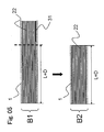
- Fig. 5 is a diagram illustrating a step of excising the precursor B1 of the tissue regenerating instrument shown in Fig. 4.
- Fig. 1 is a diagram showing a tissue regenerating instrument A, which is a final object of the present invention.
- Fig. 2 is a diagram illustrating an embodiment (B) of the precursor of the tissue regenerating instrument of the present invention.
- Fig. 3 is a diagram illustrating a variation (B') of the precursor
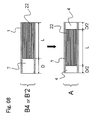
- FIG. 6 is a diagram illustrating a step of sliding and protruding a rod 22 in a saturated swelled state from the precursor B2 of the tissue regenerating instrument after the step shown in Fig. 5 and then excising the protruded portion.
- Fig. 7 is a diagram illustrating a step of excising the precursor B'1 of the tissue regenerating instrument shown in Fig. 3 swelled with a softening solvent.
- Fig. 8 is a diagram illustrating a step of sliding the rod 22 in a saturated swelled state and providing a tissue insertion space 4 at both ends after the step shown in Fig. 6 or Fig. 7.
- Fig. 1 is a diagram showing a tissue regenerating instrument A having provided a tissue inserting section on both ends thereof, which is a final object of the present invention.
- tissue regenerating instrument refers to an instrument having a longitudinal direction to be implanted in a living organism for connecting dissevered tissue ends to each other, both ends of which form tissue insertion spaces 4. Also, the tissue regenerating instrument refers to an instrument used in the field of regenerative medicine such that after implantation of the instrument, the damaged tissue regenerates along the longitudinal direction of the instrument but the instrument itself is digested and absorbed.
- the tissue targeted by the present invention is not particularly limited as far as it is a tissue that can regenerate by the capacity for regeneration of a human body.
- a nerve, a tendon, a ligament, a blood vessel, and an esophagus may be exemplified.
- the tissue regenerating instrument of the present invention is preferably used in regeneration of a nerve, tendon, and ligament.
- tissue inserting section refers to a space formed between both ends of the tissue regenerating instrument A for connecting the tissue regenerating instrument A and tissue ends.
- the longitudinal length of the tissue inserting section 4 which can be appropriately determined by one skilled in the art depending on the type of the tissue to be regenerated, is not particularly limited.
- the length of the nerve is about 2 mm to about 40 mm, preferably about 2 mm to about 10 mm from the viewpoint of facilitating insertion of the nerve.
- the length of the tendon is about 2 mm to about 60 mm, preferably about 5 mm to about 30 mm from the viewpoint of facilitating insertion of the tendon.
- the length of ligament is about 2 mm to about 60 mm, preferably about 5 mm to about 30 mm from the viewpoint of facilitating insertion of the ligament. Provision of the tissue inserting section 4 facilitates connection without requiring special suturing technique in connecting the tissue regenerating instrument A and the tissue ends and prevents growth of tissue cells toward neighboring tissues.
- the present invention provides a precursor B for producing the tissue regenerating instrument A as shown in Fig. 1.
- Fig. 2 is a diagram illustrating an embodiment of the precursor B of the tissue regenerating instrument of the present invention.
- the precursor B of the tissue regenerating instrument is provided with a lumen in the longitudinal direction and includes a tube 1 made of a biodegradable material, a rod 21 made of a biodegradable material provided in the lumen of the tube 1, and fixing means 31 and 32 that fix the rod 21 to the tube 1.
- Precursor of a tissue regenerating instrument refers to a thing produced by a physician for use in producing a target tissue regenerating instrument A depending on the state of damage of the tissue of a patient.
- the precursor B of the tissue regenerating instrument may be abbreviated as "precursor”.
- a method of producing the tissue regenerating instrument A from the precursor B may include, for example, metering of the length of the damaged tissue, metering of the length of the instrument, cutting of the instrument, swelling of the instrument and deformation of the instrument. These are described hereinbelow.
- Non-swelled state refers to a state before immersing and swelling in the solution
- saturated swelled state refers to a state in which the precursor B is immersed in the solution and the swelling is saturated.
- the immersion and swelling in the present invention are performed using a softening solvent under conditions of atmospheric pressure, at a humidity of 60% and 25 to 40°C.
- Softening solvent refers to a solution that softens the precursor B of the tissue regenerating instrument. Although physiological saline is mainly used as the softening solvent, the softening solvent is not particularly limited thereto. "Physiological saline” refers to 0.9 wt% aqueous sodium chloride solution, which is substantially isotonic with the body fluid of a human. The time until swelling reaches saturation depends on the material of the precursor B. The relation between the sate of saturated swelling and the material of the precursor B is described hereinbelow.
- Tube refers to a structure that prevents tissue cells from growing toward neighboring tissues.
- the shape of the tube 1 includes cylindrical (tubular), and prismatic (trigonal, tetragonal, pentagonal, and hexagonal).
- cylindrical (tubular) shape is preferable but the present invention is not limited thereto.
- the longitudinal length of the tube 1 depends on biological classification of subject, i.e., patient human or animal, body shape and type of tissue and hence is not particularly limited. However, it is preferable that the longitudinal length of the tube 1 is sufficiently larger than the length of a cut tissue that one skilled in the art can expect.
- the length of a cut tissue that one skilled in the art can expect is, for example, about 1 mm to about 300 mm when the tissue is a human median nerve. When the tissue is a human sciatic nerve is about 1 mm to about 500 mm.
- the longitudinal length of the tube 1 may be about 5 mm or more from the viewpoint of applicability to regeneration of all possible human nerves. From the viewpoint of suppressing an increase in production cost due to use amount of raw material, the longitudinal length of the tube 1 is preferably about 10 mm to about 200 mm.
- the longitudinal length of the tube may be about 5 mm or more, preferably about 10 mm to about 100 mm.
- the inner diameter of the tube 1 may be appropriately set by one skilled in the art based on the tissue to be regenerated and is not particularly limited.
- the inner diameter of the tube 1 is about 1 mm to about 20 mm, preferably about 1 mm to about 10 mm from the viewpoint of the possibility that the frequency of use of the tissue regenerating instrument is highest.
- the tissue is, for example, a human tendon
- the inner diameter of the tube 1 is about 1 mm to about 30 mm, preferably about 1 mm to about 20 mm.
- the tissue is, for example, a human ligament
- the inner diameter of the tube 1 is about 1 mm to about 20 mm, preferably about 1 mm to about 10 mm.
- the tube 1 is made of a biodegradable material.
- the biodegradable material refers to a material that is decomposed by itself, preferably absorbed after decomposition when the biodegradable material is implanted in a living organ.
- polylactic acid, polyglycolic acid, ⁇ -aminocaprolactone, collagen, and chitosan may be exemplified.
- collagen is preferred from the viewpoint that no inflammatory reaction is caused and decomposition and absorption can be controlled by crosslinking treatment.
- Collagen refers to a major protein component that constitutes a connective tissue in animals, and the structure of main chain is constituted by (Gly-X-Y), (Gly-Pro-X), and (Gly-Pro-Hyp).
- X and Y represent each a natural or non-natural amino acid other than glycine, proline or hydroxyproline.
- the types of collagen include I, II, and III.
- I and III are preferred from the viewpoint of easy handling but collagen is not limited thereto.
- the collagen used in the present invention includes gelatin, which is thermally modified collagen. From the viewpoint of cell adhesion, collagen is preferable.
- Collagen can be produced by extraction, chemical peptide synthesis, and recombinant DNA method.
- collagen obtained by extraction from a living tissue from the viewpoint of production cost.
- the living tissues may be derived from, for example, oxen, pigs, rabbits, sheep, rats, birds, fish, and humans.
- the living organism tissue include skin, tendon, bone, cartilage and internal organs of the animals described above. One skilled in the art can select these appropriately and the present invention is not limited to these.
- collagen treated to be soluble in solvents is selected.
- solubilized collagens such as enzyme-solubilized collagen, acid-solubilized collagen, alkali-solubilized collagen, and neutral-solubilized collagen may be exemplified.
- acid-solubilized collagen is preferable.
- atelocollagen which is a collagen subjected to treatment of removing a telopeptide, an antigen-determinant group, is preferable.
- the method of producing the tube 1 includes, for example, (i) a method of directly molding into the tube 1 by an industrial production method such as injection molding, compression molding and extrusion molding, (ii) producing a membrane substance such as film, woven fabric and nonwoven fabric and molding the membrane substance into a tube, and (iii) a method of producing a monofilament by a spinning method and molding the monofilament into a tube.
- industrial production method such as injection molding, compression molding and extrusion molding
- a membrane substance such as film, woven fabric and nonwoven fabric and molding the membrane substance into a tube
- a method of producing a monofilament by a spinning method and molding the monofilament into a tube can be appropriately set by one skilled in the art depending on the raw materials of the tube 1.
- the raw material is collagen
- the method of producing a monofilament by a spinning method or the like and molding the monofilament to a tube is preferable from the viewpoint of easy production and low production cost.
- the monofilament may be those produced by a wet spinning method, a dry spinning method, and a melt spinning method.
- a wet spinning method when the raw material is collagen, one produced by a wet spinning method is preferably from the viewpoint of easy production and low production cost.
- the wet spinning method is performed, for example, by discharging an aqueous solution of a biodegradable polymer in a coagulation bath using a gear pump, a dispenser and various pumping devices.
- a dispenser is preferable from the viewpoint of exhibiting less pulsation to discharge a constant amount of a solution stably.
- the aperture of discharge nozzles is about 10 ⁇ m to about 200 ⁇ m, preferably about 50 ⁇ m to about 150 ⁇ m from the viewpoint of further increasing the strength of monofilament.
- the concentration of the aqueous solution is about 0.1 wt% to about 20 wt%, preferably about 1 wt% to about 10 wt% from the viewpoint of the strength of the monofilament.
- the solvent of the coagulation bath used the wet spinning is not particularly limited as far as the solvent is a solvent, a suspension, an emulsion, and a solution that coagulate the biodegradable polymer.
- the solvent is a solvent, a suspension, an emulsion, and a solution that coagulate the biodegradable polymer.
- inorganic salt aqueous solutions when collagen is used as a raw material for a thread, inorganic salt aqueous solutions, inorganic salt-containing organic solvents, alcohols, and ketones can be exemplified.
- the inorganic salt aqueous solution include sodium sulfate, sodium chloride, ammonium sulfate, calcium chloride, and magnesium chloride. Solutions obtained by dissolving or dispersing the inorganic salts in alcohols or acetones may be used.
- Examples of the alcohols include methanol, ethanol, isopropanol, amyl alcohol, pentanol, hexanol, and ethylene glycol.
- Examples of the ketones include acetone and methyl ethyl ketone. Among these, ethanol and sodium chloride-dispersed ethanol dispersion are preferably used from the viewpoint of high strength of the spun filament.
- the thread of biodegradable material discharged in coagulation bath is taken up from the coagulation bath and passed through a drying step and wound around a cylindrical column to be molded as a tube 1.
- the drying step may be performed under conditions such that the collagen is no thermally denatured, the droplets from the coagulation bath attached to the periphery of the monofilament are removed, and the monofilament is not broken.
- the solvent it is preferable that the solvent remains more or less in the inside of the monofilament. This is because after the monofilament is wound around into a rod, the remaining solvent weeps outside to dissolve a part of the monofilament, thereby allowing adhesion of adjacent monofilaments to each other.
- the drying method that satisfies the above-mentioned conditions includes, for example, a method of drying by supplying air under conditions of spinning speed (winding up speed or drawing speed) of about 10 m/min to about 10,000 m/min, a humidity of about 50% or less, and a temperature of 43°C or less when an aqueous collagen solution is discharged and spun in a coagulation bath of ethanol.
- winding density refers to a number of times of winding per unit length of the tube 1 in the longitudinal direction.
- the winding density of at least one layer is set less than 10 times/cm, and the winding density of the monofilament in other layers is set 10 to 30 times/cm.
- the biodegradable material used in this treatment is preferably the same material as the material of the tube 1 from the viewpoint of increasing adhesion to the material of the tube 1.
- the concentration of the biodegradable material solution is, for example, about 0.1% to about 20%(w/w), preferably about 1% to about 10% (w/w) from the viewpoint of easy handling when the biodegradable polymer is collagen.
- the tube 1 is further subjected to crosslinking treatment as necessary.
- the crosslinking treatment enables in vivo decomposition time of the tissue regenerating instrument A produced from the precursor to be controlled.
- the crosslinking method include chemical crosslinking with crosslinking agents, ⁇ -ray irradiation, ultraviolet ray irradiation, electron beam irradiation, plasma irradiation, and thermal dehydration crosslinking.
- thermal dehydration crosslinking is preferred from the viewpoint of safety when implanted in a living organism.
- the condition of thermal dehydration crosslinking is such that the crosslinking temperature is about 100°C to about 140°C and the crosslinking time is 6 to 72 hours.
- the crosslinking temperature is about 110°C to about 130°C, and the crosslinking time is 12 to 48 hours.
- a rod 21 in a non-swelled state is provided.
- “Rod” refers to a foothold that induces growth of cells of the damaged tissue to grow in the longitudinal direction.
- the form of the foothold is, for example, a bundle of a plurality of threads made of a biodegradable material arranged substantially in parallel having a rod-like appearance.
- “Filament bundle” refers to a thing constituted by threads made of a biodegradable material, in which all the threads are arranged substantially in parallel to the longitudinal direction of the tube 1 and adjacent threads are adhered to each other.
- “Thread” is a collective or generic term for a monofilament or a twist yarn. In particular, the thread is preferably a monofilament from the viewpoint of low production cost. Monofilament can be produced in the same production method as the monofilament that constitutes the tube 1.
- the occupied cross-sectional area in a direction perpendicular to the longitudinal direction of the rod 21 in a non-swelled state is smaller than the cross-sectional area of the lumen of the tube 1.
- a ratio of the occupied cross-sectional area in a direction perpendicular to the longitudinal direction of the tube 1 is set to 5 to 10. Accordingly, the amount of the material of filament bundle is requisite minimum, so that the cost of the material can be suppressed.
- “Occupied cross-sectional area” refers to an area of a figure surrounded by an outermost peripheral line around the rod on a plane perpendicular to the longitudinal direction of the rod 1 and a void in the area is not taken into consideration.
- the rod 21 of the present invention is a filament bundle
- a gap invariably occurs between a plurality of threads that constitute the filament bundle. It is obvious that even in the case of hexagonal closes packing, which is the closest state, the gap invariably, occurs between the pluralities of threads that constitute the filament bundle.
- “Occupied cross-sectional area” refers absolutely to an area of surface surrounded by line of periphery of filament bundle and a gap is not taken into consideration.
- the occupied cross-sectional area perpendicular to the longitudinal direction of the rod 21 is smaller than the cross-sectional area of the lumen of the tube, in other words, a state where the rod 21 is localized on the inner wall of the tube 1. Therefore, the occupied cross-sectional area of the rod 21 is smaller than the lumen cross-sectional area of the tube 1, so that the operation of inserting the rods 21 in the lumen of the tube 1 is easy. Further, the tube 1 after the rod 21 is inserted therein has a longitudinal space, so that in the swelling operation described hereinbelow, the softening solvent can sufficiently penetrate into the inside of the tube to uniformly swell the rod 21. In addition, the penetration of the softening solvent into the precursor B is sufficiently fast, the time of swelling operation at the site of surgical operation can be shortened. In the present invention, the "space having a longitudinal direction" is also referred to a "fluid passage".
- the occupied cross-sectional area in a plane perpendicular to the longitudinal direction of the rod 22 in a saturated swelling state by the swelling described hereinafter is substantially the same as the lumen cross-sectional area of the tube 1 (Fig. 4). Substantially the same means to such an extent that assuming the lumen cross-sectional area of the tube 1 is 100, a ratio of the occupied cross-sectional area of a plane perpendicular to the longitudinal direction of the tube 1 to the lumen cross-sectional area of the lumen 1 is 90 to 100.
- the rod 22 in a saturated swelled state contacts the lumen of the tube 1 such that the rod 22 will not drop out from the lumen of the tube 1 and further that the occupied volume of the fluid passage 5 is extremely decreased by swelling of the rod 21, preferably to such an extent that there is no fluid passage 5 itself.
- the occupied cross-sectional area is treated to have the same meaning as described above.
- the ratio is a value obtained by swelling in a softening solvent such as physiological saline as is, with the rod being not inserted in the lumen of the tube 1. That is, the occupied cross-sectional are of the rod 22 in a saturated swelled state is substantially the same as the lumen cross-sectional area of the tube 1, so that the tube 1 is neither deformed nor broken. Further, the rod 22 in a saturated swelled state can slide in the lumen of the tube 1 in such a state that an appropriate wetting and friction resistance exist between the inner wall of the tube 1 and the rod 22 in a saturated swelled state.
- the occupied volume of the rod 22 in a saturated swelled state at a temperature (at about 25°C) at which the rod is allowed to swell in a softening solvent and the occupied volume of the rod 22 in a saturated swelled state at a temperature (about 37°C) at which the rod 22 is implanted in a living organism may differ.
- the swelling property of the rod 2 can be appropriately set, for example, such that the ratio of the occupied cross-sectional area of the plane perpendicular to the longitudinal direction to the cross-sectional area of the lumen of the tube 1 being taken as 100 is 90 to 95 at a temperature (abut 25°C) at which the rod 22 is swelled in the softening solvent or 96 to 100 at a temperature (about 37°C) at which the rod 22 is implantd in a living organism.
- the appearance configuration of the rod is not particularly limited and may be, for example, a tetragonal prism, a trigonal prism or a circular column.
- the shape of the rod 21 is preferably the same shape as that of the tube 1.
- the rod 21 is also circular column.
- the method of forming a filament bundle is exemplified by a method in which after a wet spinning is performed, the monofilament is wound around a tetragonal plate or frame with at least opposing two sides being parallel such that the monofilament is substantially perpendicular to the two sides and the wound up monofilament is cut near the two sides to obtain a filament bundle.
- the speed of winding up by the plate or frame can be the same as the above-mentioned conditions under which the tube is produced from the monofilament.
- a filament bundle is obtained by binding up a plurality of threads such that the ratio of the occupied cross-sectional area is perpendicular to the longitudinal direction of the filament bundle to the lumen cross-sectional area of the tube 1 being taken as 100 is about 5 to about 10.
- Making the ratio of the occupied cross-sectional area perpendicular to the longitudinal direction of the filament bundle to the lumen cross-sectional area of the tube 1 being taken as 100 about 5 to about 10 can be achieved, for example, by binding up about 200 to about 250 monofilaments having an outer diameter of about 50 ⁇ m to a tube having an inner diameter of about 3.0 mm.
- the occupied cross-sectional area of the filament bundle to the lumen cross-sectional are being taken as 100 is 90 to 100.
- the method of adhering can be, for example, a method in which a filament bundle is immersed in a solution of a biodegradable polymer and then dried.
- a method in which the filament bundle is immersed in water is exemplified.
- the crosslinked collagen when immersed in an aqueous solution, is slightly dissolved around the collagen monofilament. The dissolved collagen attaches to adjacent contacting collagen monofilaments, so that drying completes the adhesion.
- the aqueous solution in which the filament bundle is immersed is not particularly limited and includes water itself.
- the filament bundle obtained by the above-mentioned method has not been subjected to neutralization treatment, so that a neutralization solution can be selected as the aqueous solution.
- the neutralization solution can be selected as appropriate by one skilled in the art.
- the filament bundle obtained by binding up collagen monofilaments obtained by acid-soluble collagen can be neutralized with a basic aqueous solution such as a calcium hydroxide aqueous solution, a potassium hydroxide aqueous solution or a sodium hydrogen carbonate (baking soda) aqueous solution to have adjacent threads in the filament bundle partly adhered to each other.
- tissue insertion space forming length refers to a length necessary for providing the tissue insertion space 4 on both ends.
- the tissue insertion space forming length may be abbreviated as D.
- the specific length can be about 2 to about 4 folds of the longitudinal length of the tissue insertion space 4.
- the length of the tissue insertion space forming length is preferably about 2 folds of the longitudinal length of the tissue insertion space 4, that is 4 mm to 40 mm. Since aligning one end of the tube 1 and one end of the rod 21 to each other provides a flat end surface. Hence in the present invention, the aligned ends are also called “flat ends”. On the other hand, along with this, one end of the tube 1 and one end of the rod 21 are not aligned at the other end of the precursor B and form a space 7. Hence, in the present invention, this space 7 is also referred to as "space portion".
- ⁇ Fixing means> The thus obtained rod 21 is inserted in the lumen of the tube 1. Since the ratio of the occupied cross-sectional area perpendicular to the longitudinal direction of the rod 21 to the lumen cross-sectional area of the tube 1 being taken as 100 is about 5 to about 10, this operation is very easy. However, when the rod 21 is merely inserted in the lumen of the tube 1, the rod 21 is slipped out of the lumen of the tube 1 and the rod 21 will be contaminated.
- the collagen body disclosed in JP 2005-143979A is not fixed to the tube, so that the collagen body slides in the tube. When transported or in use, the collagen body may be dropped out and contaminated.
- JP 2002-320630A the fiber made of a synthetic bioabsorbable polymer disclosed in JP 2002-320630A is not fixed to the tube but the filament bundle slides in the tube. Therefore, similar problems as those of JP 2005-143979A are encountered.
- JP 2002-320630A it is conceivable to densely fill the fiber made of a synthetic bioabsorbable polymer in the lumen of the tube.
- the tube may be deformed due to swelling with the softening solvent used before implantation of the tube in the tissue.
- a fixing means 31, 32 that fixes the rod 21 to the tube 1.
- mere provision of the fixing means 31, 32 does not enable production of the tissue regenerating instrument A provided with the tissue insertion space 4 for inserting a tissue on both ends thereof, which is an object of the present invention.
- the instrument disclosed in JP 2004-208808A is cut according to the length of the nerve to be regenerated and the nerve end on the side of a central nerve is inserted into the space portion to effect implantation.
- the matrix and/or nerve guidepath when transported or in use since the matrix and/or a nerve guidepath is fixed to the tube, there arises the problem that end-to-end suture must be performed since a flat end is formed on the peripheral nerve side.
- the precursor B of the present invention is provided with the fixing means 31, 32 for fixing the rod 21 to the tube 1.
- the fixing means 31, 32 are made of a material or of a structure such that upon production or transport of the precursor B.
- the fixation is released and the rod 22 in a saturated swelled state can slide in the lumen of the tube 1 when the rod 21 is fixed to the tube 1 but upon production of the organ regenerating instrument A from the precursor B.
- an embodiment that the fixing means 31 is arranged at a position to be excised and firmly fixed is exemplified in an adjustment of the length of the tissue regenerating instrument A produced from the precursor B. That is, as illustrated in Fig. 2, this embodiment is one in which the fixing means 31 is provided on a portion of the inner wall of the excised region of the tube 1.
- "Excised portion of tube” refers to a portion of the precursor B to be excised upon adjustment of the length of the precursor B. More particularly, the excised portion of tube is a region in a range of length of a ratio of 0.01 to 50% from one end when the longitudinal length of the tube 1 is taken as 100%.
- the excised portion is minimum, and the excised portion is a region in a range of ratio of length of preferably 0.01 to 30%, particularly preferably 0.01 to 10%. That is, when a portion of the precursor B including the fixing means 31 is excised, the rod 22 in a saturated swelled state becomes slidable in the lumen of the tube 1.
- fixing means 31 in the first embodiment above for example, any one selected from the group consisting of a thread, a stapler, an adhesive, and combinations thereof are exemplified. Fixing with the thread or stapler is achieved by penetrating the rod 21.
- Adhesive refers to a substance that is present between the tube 1 and the rod 21 and bonds them together through anchoring effect, physical adsorption, covalent bond, ionic bond, hydrophobic bond, coordination bond, and hydrogen bond.
- the adhesive one that is scarcely soluble in water and has excellent storage stability is selected as appropriate.
- polymer compositions containing a nonbiodegradable polymer such as acrylic resins and fluorinated resins, biodegradable polymers such as crosslinked collagen, polylactate and homopolymers of hydrophobic amino acids may be exemplified.
- the adhesive is preferably biodegradable polymers such as crosslinked collagen, polylactate and homopolymers of hydrophobic amino acids, more preferably crosslinked collagen.
- the fixing means 32 is releasable.
- the position of the fixing means 32 is not particularly limited.
- the fixing means 32 in this embodiment is any one selected from the group consisting of, for example, a thread, a stapler, a binder and combinations thereof. Fixing with a thread or stapler can be made by penetrating the rod 21 from the outer wall of the tube 1. The release of the fixing means 32 may be achieved by physically removing the fixing means 32 as is.
- binder refers to a substance that bonds the tube 1 and the inducing member 21 to each other, but that can release the binding by dissolving in a good solvent of the polymers constituting itself.
- a good solvent is termed as a binder solvent.
- the binder solvent should not dissolve the precursor B itself during the treatment, the binder solvent must be a poor solvent to the biodegradable polymer that constitutes the precursor B.
- the binder solvent is determined, the polymer constituting the binder can be selected with ease.
- the biodegradable polymer is collagen and the collagen is crosslinked, almost all solvents can be applied excluding strong acids or strong alkalis that decompose the main skeleton of the collagen.
- the solvent include water, methanol, ethanol, acetone, hexane, benzene, xylene, 1,2-dichloromethane, chloroform, tetrahydrofuran, and dimethyl sulfoxide.
- water is preferable.
- the present invention is not limited thereto.
- Water includes city water, distilled water, reverse osmotic water, deionized water, and so on. Further, water may contain physiologically acceptable salts. That is, physiological saline can be used.
- the tissue regenerating instrument A is swelled with a softening solvent in order to increase handleability in suturing upon implantation.
- physiological saline is generally used. Accordingly, the water is preferably physiological saline from the viewpoint that the step of swelling the precursor B of the present invention and the step of releasing the binder can be performed simultaneously.
- such a polymer constituting the binder is not particularly limited as far as the polymer is a hydrophilic polymer.
- examples of such a hydrophilic polymer include non-crosslinked collagen, polylysine, polyglutamate, polyethylene glycol, and glycosaminoglycans such as alginic acid, chitosan, hyaluronic acid and chondroitin sulfate.
- non-crosslinked collagen is preferable from the viewpoint of high adhesion with the crosslinked collagen and no affection on the living organism if remained in the precursor B after the treatment.
- tissue regenerating instrument A a tissue regenerating instrument A from a precursor B of the tissue regenerating instrument of the present invention is described referring to the attached diagram illustrating.
- the precursor B of the tissue regenerating instrument is wholly made of collagen and the fixing means is a non-crosslinked collagen binder.
- the present invention should not be considered as being limited thereto as described above.
- the production method of tissue regenerating instrument A of the present invention includes:
- a precursor B of the tissue regenerating instrument of the present invention is immersed in a softening solvent to soften the precursor B in order to increase the handleability of suture upon implantation.
- a softening solvent mainly physiological saline is used.
- the conditions are atmospheric pressure, a humidity of 60%, and a softening solvent at 25 to 40°C.
- step (2) Releasing the fixing means 31, 32 to make the rod 2 slidable in the lumen of the tube 1
- This step (2) differs in content depending on the embodiment of the fixing means 31, 32.
- the fixing means 31, 32 are in a first mode, that is, in a mode in which the fixing means 31 is arranged in the excision region of the tube 1.
- the step (2) is performed together with the step (3) described hereinafter. This is because in the step (3) described hereinafter, the fixing means 31 arranged in the excised region of the tube 1 is excised.
- the fixing means is in a second mode, namely, releasable, the fixing means 32 in the second mode can be removed as is.
- the fixing means 32 can be released by treating the fixing means 32 with the binder solvent.
- the binder is a hydrophilic polymer that is soluble in water
- the hydrophilic polymer is dissolved in physiological saline in the above-mentioned step (1), so that this step (2) can be omitted and thus is preferable.
- the occupied cross-sectional area of the rod 22 in a saturated swelled state is substantially the same as the lumen cross-sectional area of the tube. Accordingly, the rod 22 in a saturated swelled state can slide in the lumen of the tube 1 but will not slip out of the lumen.
- the tissue to be regenerated is nerve
- the length (L) of the nerve to be regenerated is 100 mm
- the tissue insertion space forming length is 20 mm
- the precursor B2 is excised such that the length of the precursor B2 is 120 mm. Excision can be performed by using a cutting instrument such as scissors, microtome or a surgical knife. Note that the length of the precursor B corresponds to the length of the tissue to be regenerated before this step (3) is performed, this step is deemed to have been performed with doing nothing particular.
- the fixing means is in the first mode, that is, in the case where the fixing means 31 is arranged in the excision region of the tube 1, the step (3) can be performed simultaneous with the step (2).
- the fixing may be released by pressing the rod 22 in a saturated swelled state in the longitudinal direction because the remaining amount of the fixing means 31 is small.
- the tissue to be regenerated is nerve
- the tissue insertion space forming length (D) is 20 mm
- the length of the precursor B2 is 120 mm
- the longitudinal length of the rod 22 obtained by the above-mentioned operation is 100 mm.
- the tissue regenerating instrument A produced from the precursor B of the tissue regenerating instrument of the present invention can be implanted only by inserting tissue ends since the tissue regenerating instrument A is provided with the tissue insertion space 4 on both ends thereof, so that implantation operation can be readily performed without performing suture. Further, the bad effect that cells grow on the outer surface of the tube 1 can be prevented.
- Example 1 Production of precursor B of tissue regenerating instrument
- Enzyme-solubilized collagen was dissolved in water to prepare a 5% (w/w) aqueous solution.
- the collagen solution was discharged in a 99.5% (v/v) ethanol coagulation bath to spin a collagen monofilament having a diameter of about 200 ⁇ m.
- the collagen monofilament drawn up from the ethanol coagulation bath as it was wound around a cylindrical mold made of a polyfluoroethylene fiber having an outer diameter of 3.0 mm at a speed of about 4,000 m/min and dried. Then, the product was immersed in a 5% (w/w) collagen aqueous solution and dried to form the innermost layer of the tube 1.
- the collagen monofilament was again wound around an outer periphery of the innermost layer of the tube 1 at a speed of about 4,000 m/min and the resultant was subjected to thermal dehydration crosslinking reaction in a vacuum dry oven (manufactured by EYELA Co., VOS-300VD Model) under reduced pressure (1 torr or less) at 120°C for 24 hours.
- the obtained collagen tube was again immersed in a 5% (w/w) collagen aqueous solution and dried, and then subjected to the thermal crosslinking reaction to produce a tube 1 made of crosslinked collagen having an inner diameter of 3.0 mm, an outer diameter of 3.3 mm, and a length of 70 mm.
- the wound filament was cut to a length of about 50 mm and bound to produce a cylindrical column having an outer diameter of about 1.0 mm.
- the cylindrical bundle was impregnated in a 7.5% (w/w) sodium hydrogen carbonate aqueous solution and dried to prepare a rod 21 having an outer diameter of about 1.0 mm and a length of 50 mm made of a filament bundle of monofilaments made of crosslinked collagen.
- the longitudinal length of the rod 21 was shorter than the longitudinal length of the tube 1 by 20 mm. That is the tissue insertion space forming length (D) was 20 mm. Assuming the lumen cross-sectional area of the tube 1 is 100, the ratio of the cross-sectional area of the rod 21 perpendicular to the longitudinal direction of the rod 21 to the cross-sectional are of the tube 1 was about 11.1.
- the rod 21 in the lumen on one end of the tube 1, the rod 21 is present and a flat end 6 is formed while in the lumen on the other end of the tube 1, the rod 21 is absent and a space portion 7 is formed.
- the thus-obtained precursor B was subjected to 25 kGy ⁇ -ray sterilization treatment.
- Example 2 Production of a tissue regenerating instrument A
- the precursor B of the tissue regenerating instrument obtained in Example 1 was immersed in physiological saline under atmospheric pressure, at a humidity of 60% and 25°C for 20 minutes to render the precursor B of the instrument in a saturated swelled state.
- the precursor B'1 containing the fixing means 31 was excised using a microtome (Fig. 7: B'1 to B'2). That is, the longitudinal length of the tube 1 was 50 mm, the longitudinal length of the rod 22 in a saturated swelled state (L: length of tissue to be regenerated) was 30 mm.
Landscapes
- Health & Medical Sciences (AREA)
- Epidemiology (AREA)
- Dermatology (AREA)
- Medicinal Chemistry (AREA)
- Oral & Maxillofacial Surgery (AREA)
- Transplantation (AREA)
- Chemical & Material Sciences (AREA)
- Life Sciences & Earth Sciences (AREA)
- Animal Behavior & Ethology (AREA)
- General Health & Medical Sciences (AREA)
- Public Health (AREA)
- Veterinary Medicine (AREA)
- Materials For Medical Uses (AREA)
- Prostheses (AREA)
Applications Claiming Priority (1)
| Application Number | Priority Date | Filing Date | Title |
|---|---|---|---|
| JP2006223424A JP4569543B2 (ja) | 2006-08-18 | 2006-08-18 | 膨潤可能な棒状体を備えた組織再生器具の前駆体 |
Publications (3)
| Publication Number | Publication Date |
|---|---|
| EP1891986A2 true EP1891986A2 (de) | 2008-02-27 |
| EP1891986A3 EP1891986A3 (de) | 2009-06-10 |
| EP1891986B1 EP1891986B1 (de) | 2011-03-30 |
Family
ID=38922778
Family Applications (1)
| Application Number | Title | Priority Date | Filing Date |
|---|---|---|---|
| EP20070015875 Not-in-force EP1891986B1 (de) | 2006-08-18 | 2007-08-13 | Vorläufer eines Instruments zur Gewebe-Wiederherstellung mit einer quellbaren Stange |
Country Status (5)
| Country | Link |
|---|---|
| US (1) | US8328826B2 (de) |
| EP (1) | EP1891986B1 (de) |
| JP (1) | JP4569543B2 (de) |
| AT (1) | ATE503504T1 (de) |
| DE (1) | DE602007013497D1 (de) |
Families Citing this family (4)
| Publication number | Priority date | Publication date | Assignee | Title |
|---|---|---|---|---|
| JP5703804B2 (ja) * | 2011-02-08 | 2015-04-22 | ニプロ株式会社 | 組織再生器具の前駆体、その製造方法 |
| CN103892937B (zh) * | 2014-04-21 | 2016-08-17 | 清华大学 | 一种医用生物组织结构及其制备方法和专用设备 |
| JP2024020670A (ja) * | 2020-12-25 | 2024-02-15 | ニプロ株式会社 | 成長誘導部材及び組織再生器具 |
| JP7707845B2 (ja) * | 2021-10-15 | 2025-07-15 | ニプロ株式会社 | 被浸漬部材用容器 |
Family Cites Families (30)
| Publication number | Priority date | Publication date | Assignee | Title |
|---|---|---|---|---|
| US4416028A (en) * | 1981-01-22 | 1983-11-22 | Ingvar Eriksson | Blood vessel prosthesis |
| US4669474A (en) * | 1984-01-12 | 1987-06-02 | Minnesota Mining And Manufacturing Company | Absorbable nerve repair device and method |
| US4662884A (en) * | 1984-04-25 | 1987-05-05 | University Of Utah Research Foundation | Prostheses and methods for promoting nerve regeneration |
| US4759764A (en) * | 1985-05-24 | 1988-07-26 | Clayton Foundation For Research | Peripheral nerve regeneration |
| SE457598B (sv) | 1987-03-09 | 1989-01-16 | Astra Meditec Ab | Protes foer hopskarvning av nervaendar |
| US4870966A (en) | 1988-02-01 | 1989-10-03 | American Cyanamid Company | Bioabsorbable surgical device for treating nerve defects |
| US5011486A (en) * | 1988-11-18 | 1991-04-30 | Brown University Research Foundation | Composite nerve guidance channels |
| JPH07100B2 (ja) * | 1990-01-31 | 1995-01-11 | グンゼ株式会社 | コラーゲンスポンジの乾燥法 |
| IT1247157B (it) | 1991-02-11 | 1994-12-12 | Fidia Spa | Canali di guida biodegradabili e bioassorbibili da impiegare per la rigenerazione nervosa. |
| USRE36370E (en) | 1992-01-13 | 1999-11-02 | Li; Shu-Tung | Resorbable vascular wound dressings |
| JP3457339B2 (ja) | 1992-02-27 | 2003-10-14 | 日本ハム株式会社 | 神経再生補助材及びその製造法 |
| EP1716864A1 (de) | 1993-08-26 | 2006-11-02 | Genetics Institute, LLC | Neuronale Regeneration mit menschlichen morphogenischen Knochenproteinen |
| US5656605A (en) * | 1994-01-26 | 1997-08-12 | Institute Of Molecular Biology, Inc. | Device to promote drug-induced nerve regeneration |
| US5834029A (en) | 1994-07-20 | 1998-11-10 | Cytotherapeutics, Inc. | Nerve guidance channel containing bioartificial three-dimensional hydrogel extracellular matrix derivatized with cell adhesive peptide fragment |
| TW369414B (en) | 1994-09-30 | 1999-09-11 | Yamanouchi Pharma Co Ltd | Bone formation transplant |
| SE9601243D0 (sv) * | 1996-03-29 | 1996-03-29 | Hans Arne Hansson | Promotion of regeneration of organized tissues |
| TW528600B (en) | 1996-11-20 | 2003-04-21 | Yasuhiko Shimizu | Artificial neural canal |
| US5925053A (en) | 1997-09-02 | 1999-07-20 | Children's Medical Center Corporation | Multi-lumen polymeric guidance channel, method for promoting nerve regeneration, and method of manufacturing a multi-lumen nerve guidance channel |
| JP4199342B2 (ja) | 1997-12-02 | 2008-12-17 | エフ.ホフマン−ラ ロシュ アーゲー | 自動サンプル処理装置、および自動サンプル処理装置におけるサンプル識別方法 |
| WO1999063908A1 (en) * | 1998-06-10 | 1999-12-16 | Tapic International Co., Ltd. | Artificial neural tube |
| WO2001010421A1 (en) * | 1999-08-06 | 2001-02-15 | Board Of Regents, The University Of Texas System | Drug releasing biodegradable fiber implant |
| CZ301649B6 (cs) * | 2000-06-28 | 2010-05-12 | Ed. Geistlich Soehne Ag Fur Chemische Industrie Incorporated Under The Laws Of Switzerland | Trubice pro regeneraci nervu a zpusob jejich výroby |
| DE10053611A1 (de) * | 2000-10-28 | 2002-05-02 | Inst Textil & Faserforschung | Bioresorbierbare Nervenleitschiene |
| GB0030583D0 (en) | 2000-12-15 | 2001-01-31 | Univ Nottingham | Nerve regeneration |
| JP3871525B2 (ja) | 2001-04-26 | 2007-01-24 | ニプロ株式会社 | 生体組織または器官再生用器具 |
| JP4605985B2 (ja) * | 2002-12-27 | 2011-01-05 | ニプロ株式会社 | 神経再生誘導管 |
| SE0301974D0 (sv) * | 2003-07-03 | 2003-07-03 | Astra Tech Ab | A device for promoting regeneration of an injured nerve, a kit and a biodegredable sheet for preparing such a device |
| CA2604622A1 (en) * | 2005-04-15 | 2006-10-26 | Musculoskeletal Transplant Foundation | Vertebral disc repair |
| US7737060B2 (en) * | 2006-03-31 | 2010-06-15 | Boston Scientific Scimed, Inc. | Medical devices containing multi-component fibers |
| FR2902661B1 (fr) * | 2006-06-22 | 2011-05-13 | Orthomed | Tubes de collagene |
-
2006
- 2006-08-18 JP JP2006223424A patent/JP4569543B2/ja active Active
-
2007
- 2007-08-13 EP EP20070015875 patent/EP1891986B1/de not_active Not-in-force
- 2007-08-13 AT AT07015875T patent/ATE503504T1/de not_active IP Right Cessation
- 2007-08-13 DE DE200760013497 patent/DE602007013497D1/de active Active
- 2007-08-15 US US11/889,697 patent/US8328826B2/en active Active
Non-Patent Citations (1)
| Title |
|---|
| None |
Also Published As
| Publication number | Publication date |
|---|---|
| US8328826B2 (en) | 2012-12-11 |
| EP1891986A3 (de) | 2009-06-10 |
| EP1891986B1 (de) | 2011-03-30 |
| DE602007013497D1 (de) | 2011-05-12 |
| JP4569543B2 (ja) | 2010-10-27 |
| ATE503504T1 (de) | 2011-04-15 |
| JP2008043597A (ja) | 2008-02-28 |
| US20080288084A1 (en) | 2008-11-20 |
Similar Documents
| Publication | Publication Date | Title |
|---|---|---|
| EP1254671B1 (de) | Kollagen enthaltende Vorrichtungen für Nervenregenerierung | |
| CN100453057C (zh) | 神经再生诱导管 | |
| TW458772B (en) | An artificial neural canal | |
| JP4995811B2 (ja) | 瘻治療用容積式移植片並びに関連の方法及びシステム | |
| KR20020029069A (ko) | 인공 신경관 | |
| KR20000057129A (ko) | 인공 신경관 | |
| JP3726280B2 (ja) | 医療用コラーゲン膜 | |
| JP5320726B2 (ja) | コラーゲン繊維束の製造方法 | |
| EP1891986B1 (de) | Vorläufer eines Instruments zur Gewebe-Wiederherstellung mit einer quellbaren Stange | |
| JP4765602B2 (ja) | 再生医療用器具の包装体及び再生医療用器具用の処理方法 | |
| JP2001070436A (ja) | 生体管構造を形成するためのコラーゲン支持体 | |
| JP5703804B2 (ja) | 組織再生器具の前駆体、その製造方法 | |
| JP5017936B2 (ja) | 切除領域に固定手段を備えた組織再生器具の前駆体 | |
| JP5563182B2 (ja) | 解除可能な固定手段を備えた組織再生器具の前駆体 | |
| EP3338817B1 (de) | Prothese mit einem chitosankern für zur regeneration der nerven und verfahren zu deren herstellung | |
| JP4345296B2 (ja) | 癒着防止膜 | |
| CN114681671B (zh) | 组织修复膜 | |
| JP4595279B2 (ja) | 癒着防止膜 | |
| JP2012250069A (ja) | 解除可能な固定手段を備えた組織再生器具の前駆体 | |
| JP2007050263A (ja) | 生体組織または器官再生用器具 | |
| JP2021023728A (ja) | 組織再生基材 | |
| JPWO1998022155A1 (ja) | 人工神経管 | |
| HK1131570A (en) | Thin film multilocular structure comprising collagen, material for tissue regeneration containing the same and method for producing the same |
Legal Events
| Date | Code | Title | Description |
|---|---|---|---|
| PUAI | Public reference made under article 153(3) epc to a published international application that has entered the european phase |
Free format text: ORIGINAL CODE: 0009012 |
|
| AK | Designated contracting states |
Kind code of ref document: A2 Designated state(s): AT BE BG CH CY CZ DE DK EE ES FI FR GB GR HU IE IS IT LI LT LU LV MC MT NL PL PT RO SE SI SK TR |
|
| AX | Request for extension of the european patent |
Extension state: AL BA HR MK YU |
|
| PUAL | Search report despatched |
Free format text: ORIGINAL CODE: 0009013 |
|
| AK | Designated contracting states |
Kind code of ref document: A3 Designated state(s): AT BE BG CH CY CZ DE DK EE ES FI FR GB GR HU IE IS IT LI LT LU LV MC MT NL PL PT RO SE SI SK TR |
|
| AX | Request for extension of the european patent |
Extension state: AL BA HR MK RS |
|
| 17P | Request for examination filed |
Effective date: 20091125 |
|
| AKX | Designation fees paid |
Designated state(s): AT BE BG CH CY CZ DE DK EE ES FI FR GB GR HU IE IS IT LI LT LU LV MC MT NL PL PT RO SE SI SK TR |
|
| 17Q | First examination report despatched |
Effective date: 20100401 |
|
| GRAP | Despatch of communication of intention to grant a patent |
Free format text: ORIGINAL CODE: EPIDOSNIGR1 |
|
| GRAS | Grant fee paid |
Free format text: ORIGINAL CODE: EPIDOSNIGR3 |
|
| GRAA | (expected) grant |
Free format text: ORIGINAL CODE: 0009210 |
|
| RIN1 | Information on inventor provided before grant (corrected) |
Inventor name: NOTAZAWA, SHUNSUKE Inventor name: DOI, NOBUTOSHI |
|
| AK | Designated contracting states |
Kind code of ref document: B1 Designated state(s): AT BE BG CH CY CZ DE DK EE ES FI FR GB GR HU IE IS IT LI LT LU LV MC MT NL PL PT RO SE SI SK TR |
|
| REG | Reference to a national code |
Ref country code: GB Ref legal event code: FG4D |
|
| REG | Reference to a national code |
Ref country code: CH Ref legal event code: EP |
|
| REG | Reference to a national code |
Ref country code: IE Ref legal event code: FG4D |
|
| REF | Corresponds to: |
Ref document number: 602007013497 Country of ref document: DE Date of ref document: 20110512 Kind code of ref document: P |
|
| REG | Reference to a national code |
Ref country code: DE Ref legal event code: R096 Ref document number: 602007013497 Country of ref document: DE Effective date: 20110512 |
|
| REG | Reference to a national code |
Ref country code: NL Ref legal event code: VDEP Effective date: 20110330 |
|
| PG25 | Lapsed in a contracting state [announced via postgrant information from national office to epo] |
Ref country code: LT Free format text: LAPSE BECAUSE OF FAILURE TO SUBMIT A TRANSLATION OF THE DESCRIPTION OR TO PAY THE FEE WITHIN THE PRESCRIBED TIME-LIMIT Effective date: 20110330 Ref country code: GR Free format text: LAPSE BECAUSE OF FAILURE TO SUBMIT A TRANSLATION OF THE DESCRIPTION OR TO PAY THE FEE WITHIN THE PRESCRIBED TIME-LIMIT Effective date: 20110701 Ref country code: LV Free format text: LAPSE BECAUSE OF FAILURE TO SUBMIT A TRANSLATION OF THE DESCRIPTION OR TO PAY THE FEE WITHIN THE PRESCRIBED TIME-LIMIT Effective date: 20110330 Ref country code: SE Free format text: LAPSE BECAUSE OF FAILURE TO SUBMIT A TRANSLATION OF THE DESCRIPTION OR TO PAY THE FEE WITHIN THE PRESCRIBED TIME-LIMIT Effective date: 20110330 |
|
| LTIE | Lt: invalidation of european patent or patent extension |
Effective date: 20110330 |
|
| PG25 | Lapsed in a contracting state [announced via postgrant information from national office to epo] |
Ref country code: AT Free format text: LAPSE BECAUSE OF FAILURE TO SUBMIT A TRANSLATION OF THE DESCRIPTION OR TO PAY THE FEE WITHIN THE PRESCRIBED TIME-LIMIT Effective date: 20110330 Ref country code: SI Free format text: LAPSE BECAUSE OF FAILURE TO SUBMIT A TRANSLATION OF THE DESCRIPTION OR TO PAY THE FEE WITHIN THE PRESCRIBED TIME-LIMIT Effective date: 20110330 Ref country code: CY Free format text: LAPSE BECAUSE OF FAILURE TO SUBMIT A TRANSLATION OF THE DESCRIPTION OR TO PAY THE FEE WITHIN THE PRESCRIBED TIME-LIMIT Effective date: 20110330 Ref country code: FI Free format text: LAPSE BECAUSE OF FAILURE TO SUBMIT A TRANSLATION OF THE DESCRIPTION OR TO PAY THE FEE WITHIN THE PRESCRIBED TIME-LIMIT Effective date: 20110330 |
|
| PG25 | Lapsed in a contracting state [announced via postgrant information from national office to epo] |
Ref country code: BE Free format text: LAPSE BECAUSE OF FAILURE TO SUBMIT A TRANSLATION OF THE DESCRIPTION OR TO PAY THE FEE WITHIN THE PRESCRIBED TIME-LIMIT Effective date: 20110330 |
|
| PG25 | Lapsed in a contracting state [announced via postgrant information from national office to epo] |
Ref country code: PT Free format text: LAPSE BECAUSE OF FAILURE TO SUBMIT A TRANSLATION OF THE DESCRIPTION OR TO PAY THE FEE WITHIN THE PRESCRIBED TIME-LIMIT Effective date: 20110801 Ref country code: EE Free format text: LAPSE BECAUSE OF FAILURE TO SUBMIT A TRANSLATION OF THE DESCRIPTION OR TO PAY THE FEE WITHIN THE PRESCRIBED TIME-LIMIT Effective date: 20110330 |
|
| PG25 | Lapsed in a contracting state [announced via postgrant information from national office to epo] |
Ref country code: ES Free format text: LAPSE BECAUSE OF FAILURE TO SUBMIT A TRANSLATION OF THE DESCRIPTION OR TO PAY THE FEE WITHIN THE PRESCRIBED TIME-LIMIT Effective date: 20110711 Ref country code: RO Free format text: LAPSE BECAUSE OF FAILURE TO SUBMIT A TRANSLATION OF THE DESCRIPTION OR TO PAY THE FEE WITHIN THE PRESCRIBED TIME-LIMIT Effective date: 20110330 Ref country code: IS Free format text: LAPSE BECAUSE OF FAILURE TO SUBMIT A TRANSLATION OF THE DESCRIPTION OR TO PAY THE FEE WITHIN THE PRESCRIBED TIME-LIMIT Effective date: 20110730 Ref country code: SK Free format text: LAPSE BECAUSE OF FAILURE TO SUBMIT A TRANSLATION OF THE DESCRIPTION OR TO PAY THE FEE WITHIN THE PRESCRIBED TIME-LIMIT Effective date: 20110330 Ref country code: CZ Free format text: LAPSE BECAUSE OF FAILURE TO SUBMIT A TRANSLATION OF THE DESCRIPTION OR TO PAY THE FEE WITHIN THE PRESCRIBED TIME-LIMIT Effective date: 20110330 |
|
| PG25 | Lapsed in a contracting state [announced via postgrant information from national office to epo] |
Ref country code: MT Free format text: LAPSE BECAUSE OF FAILURE TO SUBMIT A TRANSLATION OF THE DESCRIPTION OR TO PAY THE FEE WITHIN THE PRESCRIBED TIME-LIMIT Effective date: 20110330 Ref country code: NL Free format text: LAPSE BECAUSE OF FAILURE TO SUBMIT A TRANSLATION OF THE DESCRIPTION OR TO PAY THE FEE WITHIN THE PRESCRIBED TIME-LIMIT Effective date: 20110330 |
|
| PLBE | No opposition filed within time limit |
Free format text: ORIGINAL CODE: 0009261 |
|
| STAA | Information on the status of an ep patent application or granted ep patent |
Free format text: STATUS: NO OPPOSITION FILED WITHIN TIME LIMIT |
|
| PG25 | Lapsed in a contracting state [announced via postgrant information from national office to epo] |
Ref country code: PL Free format text: LAPSE BECAUSE OF FAILURE TO SUBMIT A TRANSLATION OF THE DESCRIPTION OR TO PAY THE FEE WITHIN THE PRESCRIBED TIME-LIMIT Effective date: 20110330 Ref country code: DK Free format text: LAPSE BECAUSE OF FAILURE TO SUBMIT A TRANSLATION OF THE DESCRIPTION OR TO PAY THE FEE WITHIN THE PRESCRIBED TIME-LIMIT Effective date: 20110330 |
|
| 26N | No opposition filed |
Effective date: 20120102 |
|
| PG25 | Lapsed in a contracting state [announced via postgrant information from national office to epo] |
Ref country code: MC Free format text: LAPSE BECAUSE OF NON-PAYMENT OF DUE FEES Effective date: 20110831 |
|
| REG | Reference to a national code |
Ref country code: CH Ref legal event code: PL |
|
| REG | Reference to a national code |
Ref country code: DE Ref legal event code: R097 Ref document number: 602007013497 Country of ref document: DE Effective date: 20120102 |
|
| PG25 | Lapsed in a contracting state [announced via postgrant information from national office to epo] |
Ref country code: CH Free format text: LAPSE BECAUSE OF NON-PAYMENT OF DUE FEES Effective date: 20110831 Ref country code: LI Free format text: LAPSE BECAUSE OF NON-PAYMENT OF DUE FEES Effective date: 20110831 |
|
| REG | Reference to a national code |
Ref country code: IE Ref legal event code: MM4A |
|
| PG25 | Lapsed in a contracting state [announced via postgrant information from national office to epo] |
Ref country code: IT Free format text: LAPSE BECAUSE OF FAILURE TO SUBMIT A TRANSLATION OF THE DESCRIPTION OR TO PAY THE FEE WITHIN THE PRESCRIBED TIME-LIMIT Effective date: 20110330 |
|
| PG25 | Lapsed in a contracting state [announced via postgrant information from national office to epo] |
Ref country code: IE Free format text: LAPSE BECAUSE OF NON-PAYMENT OF DUE FEES Effective date: 20110813 |
|
| PG25 | Lapsed in a contracting state [announced via postgrant information from national office to epo] |
Ref country code: LU Free format text: LAPSE BECAUSE OF NON-PAYMENT OF DUE FEES Effective date: 20110813 |
|
| PG25 | Lapsed in a contracting state [announced via postgrant information from national office to epo] |
Ref country code: BG Free format text: LAPSE BECAUSE OF FAILURE TO SUBMIT A TRANSLATION OF THE DESCRIPTION OR TO PAY THE FEE WITHIN THE PRESCRIBED TIME-LIMIT Effective date: 20110630 |
|
| PG25 | Lapsed in a contracting state [announced via postgrant information from national office to epo] |
Ref country code: TR Free format text: LAPSE BECAUSE OF FAILURE TO SUBMIT A TRANSLATION OF THE DESCRIPTION OR TO PAY THE FEE WITHIN THE PRESCRIBED TIME-LIMIT Effective date: 20110330 |
|
| PG25 | Lapsed in a contracting state [announced via postgrant information from national office to epo] |
Ref country code: HU Free format text: LAPSE BECAUSE OF FAILURE TO SUBMIT A TRANSLATION OF THE DESCRIPTION OR TO PAY THE FEE WITHIN THE PRESCRIBED TIME-LIMIT Effective date: 20110330 |
|
| REG | Reference to a national code |
Ref country code: FR Ref legal event code: PLFP Year of fee payment: 9 |
|
| REG | Reference to a national code |
Ref country code: FR Ref legal event code: PLFP Year of fee payment: 10 |
|
| REG | Reference to a national code |
Ref country code: FR Ref legal event code: PLFP Year of fee payment: 11 |
|
| REG | Reference to a national code |
Ref country code: FR Ref legal event code: PLFP Year of fee payment: 12 |
|
| PGFP | Annual fee paid to national office [announced via postgrant information from national office to epo] |
Ref country code: GB Payment date: 20220822 Year of fee payment: 16 Ref country code: DE Payment date: 20220620 Year of fee payment: 16 |
|
| PGFP | Annual fee paid to national office [announced via postgrant information from national office to epo] |
Ref country code: FR Payment date: 20220823 Year of fee payment: 16 |
|
| REG | Reference to a national code |
Ref country code: DE Ref legal event code: R119 Ref document number: 602007013497 Country of ref document: DE |
|
| GBPC | Gb: european patent ceased through non-payment of renewal fee |
Effective date: 20230813 |
|
| PG25 | Lapsed in a contracting state [announced via postgrant information from national office to epo] |
Ref country code: GB Free format text: LAPSE BECAUSE OF NON-PAYMENT OF DUE FEES Effective date: 20230813 |
|
| PG25 | Lapsed in a contracting state [announced via postgrant information from national office to epo] |
Ref country code: GB Free format text: LAPSE BECAUSE OF NON-PAYMENT OF DUE FEES Effective date: 20230813 Ref country code: FR Free format text: LAPSE BECAUSE OF NON-PAYMENT OF DUE FEES Effective date: 20230831 Ref country code: DE Free format text: LAPSE BECAUSE OF NON-PAYMENT OF DUE FEES Effective date: 20240301 |