EP1890954B2 - Procédé et dispositif permettant de prélever des emballages secondaires empilés sur une palette - Google Patents
Procédé et dispositif permettant de prélever des emballages secondaires empilés sur une palette Download PDFInfo
- Publication number
- EP1890954B2 EP1890954B2 EP07724976.1A EP07724976A EP1890954B2 EP 1890954 B2 EP1890954 B2 EP 1890954B2 EP 07724976 A EP07724976 A EP 07724976A EP 1890954 B2 EP1890954 B2 EP 1890954B2
- Authority
- EP
- European Patent Office
- Prior art keywords
- hold
- packages
- support plate
- rollers
- down member
- Prior art date
- Legal status (The legal status is an assumption and is not a legal conclusion. Google has not performed a legal analysis and makes no representation as to the accuracy of the status listed.)
- Active
Links
Images


Classifications
-
- B—PERFORMING OPERATIONS; TRANSPORTING
- B65—CONVEYING; PACKING; STORING; HANDLING THIN OR FILAMENTARY MATERIAL
- B65G—TRANSPORT OR STORAGE DEVICES, e.g. CONVEYORS FOR LOADING OR TIPPING, SHOP CONVEYOR SYSTEMS OR PNEUMATIC TUBE CONVEYORS
- B65G59/00—De-stacking of articles
- B65G59/02—De-stacking from the top of the stack
- B65G59/04—De-stacking from the top of the stack by suction or magnetic devices
-
- B—PERFORMING OPERATIONS; TRANSPORTING
- B65—CONVEYING; PACKING; STORING; HANDLING THIN OR FILAMENTARY MATERIAL
- B65G—TRANSPORT OR STORAGE DEVICES, e.g. CONVEYORS FOR LOADING OR TIPPING, SHOP CONVEYOR SYSTEMS OR PNEUMATIC TUBE CONVEYORS
- B65G59/00—De-stacking of articles
- B65G59/02—De-stacking from the top of the stack
- B65G59/023—De-stacking from the top of the stack by means insertable between the stacked articles or layers
-
- B—PERFORMING OPERATIONS; TRANSPORTING
- B66—HOISTING; LIFTING; HAULING
- B66C—CRANES; LOAD-ENGAGING ELEMENTS OR DEVICES FOR CRANES, CAPSTANS, WINCHES, OR TACKLES
- B66C1/00—Load-engaging elements or devices attached to lifting or lowering gear of cranes or adapted for connection therewith for transmitting lifting forces to articles or groups of articles
- B66C1/02—Load-engaging elements or devices attached to lifting or lowering gear of cranes or adapted for connection therewith for transmitting lifting forces to articles or groups of articles by suction means
- B66C1/0218—Safety measures, e.g. sensors, duplicate functions
-
- Y—GENERAL TAGGING OF NEW TECHNOLOGICAL DEVELOPMENTS; GENERAL TAGGING OF CROSS-SECTIONAL TECHNOLOGIES SPANNING OVER SEVERAL SECTIONS OF THE IPC; TECHNICAL SUBJECTS COVERED BY FORMER USPC CROSS-REFERENCE ART COLLECTIONS [XRACs] AND DIGESTS
- Y10—TECHNICAL SUBJECTS COVERED BY FORMER USPC
- Y10S—TECHNICAL SUBJECTS COVERED BY FORMER USPC CROSS-REFERENCE ART COLLECTIONS [XRACs] AND DIGESTS
- Y10S414/00—Material or article handling
- Y10S414/10—Associated with forming or dispersing groups of intersupporting articles, e.g. stacking patterns
- Y10S414/12—Associated with forming or dispersing groups of intersupporting articles, e.g. stacking patterns including means pressing against top or end of group
-
- Y—GENERAL TAGGING OF NEW TECHNOLOGICAL DEVELOPMENTS; GENERAL TAGGING OF CROSS-SECTIONAL TECHNOLOGIES SPANNING OVER SEVERAL SECTIONS OF THE IPC; TECHNICAL SUBJECTS COVERED BY FORMER USPC CROSS-REFERENCE ART COLLECTIONS [XRACs] AND DIGESTS
- Y10—TECHNICAL SUBJECTS COVERED BY FORMER USPC
- Y10T—TECHNICAL SUBJECTS COVERED BY FORMER US CLASSIFICATION
- Y10T24/00—Buckles, buttons, clasps, etc.
- Y10T24/21—Strap tighteners
- Y10T24/2143—Strap-attached folding lever
- Y10T24/2157—Tie downs [covers, articles]
Definitions
- the invention relates to a method for Entpallet Schlieren of stacked containers, with containers are frictionally raised and driven under by at least one support floor, and a device for Entpallet Schl of stacked containers, with at least one roller for lifting the container and a support base.
- the invention relates in particular to the depalletizing of containers stacked on a pallet.
- mixed palletizing different goods or packages are put together on a single pallet. This is also called mixed picking.
- One widely used application is to assemble a mixed range of goods by ordering a retail store from the wholesaler. The goods ordered by the retailer are assembled from a warehouse of the wholesaler. The desired goods are taken from unmixed pallets and individually built on a delivery pallet according to customer order. The mixed picked pallet is then sent to the purchaser, i. delivered to the retailer.
- the US 4,453,874 shows a generic device with a gripper, at the front, free end rotatable rollers are mounted.
- the rollers serve to lift by means of frictional contact with a side surface of the male goods this unilaterally, so that they can be charged to a support base of the gripper, which can do this under the goods.
- a conveyor belt may be provided on the gripper, with which the goods are transported on this.
- the rollers may be provided with a friction-increasing amount or a coating, for example, they may be formed rubberized.
- the recorded packages of goods can then be sold in reverse order on another pallet.
- Such grippers are generally installed permanently in a system or guided by a gantry system mobile.
- the disadvantage is that only a one-sided attack on the goods is possible, so that a counter-holder is necessary and, since the goods are tilted when lifting and thereby increases the distance between the counter-holder and elevator rollers, either the counter-holder or the Anheberollen must be resiliently arranged, wherein a difficult coordination between elastic Nachgebekraft and coefficient of friction of the rollers is to make.
- the DE 37 18 601 A1 shows a Depalletierwerkmaschine, which is attached to a joint robot.
- the tool has rigid blade-like receiving tongues that engage under the goods packages and can lift.
- the US 2002/0154986 A1 has a lifting plate with a very low height, which can be pushed between layers of goods, the upper layer lifts it, so that a stronger and more stable mounting plate can be pushed under the packaged goods. This tool can also be attached to a robot.
- Depalletierwerkmaschinee have the disadvantage that the Depalletiervorgang can be disturbed or impeded by a presence of loosely on the top of a bundle unit arranged objects, such as covers or cover layers in various designs or materials, sensitive. Thus, for example, a slipping or jamming of such objects during a discharging process can lead to a complete failure of a known depalletizing tool with a considerable time and repair effort associated therewith.
- U.S. Patent 5,265,712 is a device for receiving is especially heavy containers known. It has a lower conveyor belt with a front roller and an auxiliary element with another roller. This imposes a horizontal force on an edge of the top of the container, which, together with a frictional force which results from the front roller of the lower conveyor belt, a torque which tilts the container so that it can be conveyed away from the lower conveyor belt.
- the invention is based on the object, starting from the aforementioned prior art while avoiding the disadvantages mentioned to reliably depalletise products in various packaging forms.
- a generic device for solving the above problem provides at least two opposing rollers.
- a safe and reliable lifting of stacked containers for removal is made possible by frictionally attacked on at least two opposite sides of the container.
- the container on the one hand in parallel alignment to the package layers, in particular raised vertically, on the other hand is achieved by the fact that is attacked by frictional engagement on two opposite sides, a higher reliability.
- a difficult coordination between the coefficient of friction of the lifting elements, just like rollers and horizontal these oppressive against the container yielding or elastic force avoided because the lever elements can be pressed with such a maximum force against the container, the so big is that it just does not damage the containers.
- the containers are lifted by means of rollers, which rotate for this purpose, in which case the upwardly lifted containers of at least two sides, each with one support base part, are driven under.
- the underride takes place from two opposite sides.
- a device provides that the support floor has at least two mutually movable support base parts.
- a symmetrical design thus, this is not overly bulging unilaterally.
- this also improves the picking and gripping the container and provided with greater security.
- the rollers can be driven by at least one roller drive motor, wherein in particular the rollers can be driven by belts from the at least one roller motor.
- the support base parts are slidable via drivers, in particular, in turn, the support base parts by means of drive belt, possibly via the driver are displaced.
- the support floor parts are displaceable over at least one distributor shaft, wherein furthermore the distributor shaft can be driven by at least one motor via at least one toothed belt.
- the invention For positioning the recorded container, the invention provides in a development of a fixed stop and a relative to this movable stop for positioning of the container before, in particular the movable stop by means of at least one cylinder, preferably as a pneumatic cylinder, is displaceable.
- a centering device is provided in a preferred embodiment, which is in particular designed such that at least one parallel to the direction of Warrekkungscardi two rollers slide plate is provided for centering the container, further comprising two mutually displaceable sliding plates can be provided.
- a specific embodiment provides that the sliding plates are displaceable by at least one centering motor, preferably via toothed belt, wherein in particular the sliding plates are synchronously movable.
- the device according to the invention has, as is known per se from the prior art, a connection coupling for connection to a robot.
- At least one hold-down acts on the top of the container.
- a slipping or tilting of objects arranged on the upper side of the container unit and not fixed to the container unit can thereby be reliably avoided.
- These may in particular be loosely positioned covers or cover layers in different embodiments or materials, as they are usually arranged for protection purposes on the surface of containers.
- the invention provides to solve this problem that a hold-down on the top of the container is arranged.
- a hold-down is formed substantially plate-shaped. This can be achieved on the one hand that the holddown covers the entire top of a container, on the other hand remains easy to position.
- such a hold-down device is furthermore designed to be so flexible that it can essentially be adapted to the surface shape of the container.
- a particularly high degree of operational reliability can also be achieved in the case of individual objects arranged on certain subregions of the surface, since according to the invention, therefore, a securing is ensured essentially along the entire top of the container.
- the hold-down of chain-like material in particular hinge bands made of plastic or metal is formed.
- the hold-down of carpet-shaped braided material, in particular wire or cloth may be formed.
- Such a choice of material makes it possible according to the invention to adapt the hold-down to the respective contours of a respective package layer.
- the hold-down can also be rigid. In this way, a particularly high contact pressure of the blank holder on the surface of the container can be achieved.
- Other embodiments of the hold-down provide a geradflambaige or sagging training.
- the hold-down device can be moved vertically from an upper position to an under position.
- the lower position corresponds to that position in which the hold-down comes into frictional contact with the surface of the container top. In this way, an on-demand use of the hold-down is possible. If the hold-down device is not required, it is provided that it remains in its upper position when carrying out the method according to the invention.
- the hold-down is infinitely movable, in particular the travel height or width infinitely adjustable.
- the hold-down is guided by linear units, thereby enabling a need-precise method.
- the linear guidance of the hold-down takes place on its respective sides or corners, in particular on four sides.
- a precisely switchable design of a hold-down device provides that it can be moved pneumatically and / or motorically.
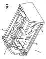
- the Fig. 1 is an overview view in which a device according to the invention for Depallet Schl is connected to a robot which engages around the uppermost layer of a container stack located on a pallet in order to lift them from the rest of the stack.
- the depalletizing tool according to the invention has a base frame 1, on the underside of which two support base parts 2a and 2b, here as support floor halves, can be moved towards and away from one another by means of sliding bearings 3a, 3b.
- a common electrically driven motor 4 is provided, which drives a distributor belt 6 via a first toothed belt 5, which drives a right drive belt 7a and a left drive belt 7b.
- the drive belts 7a and 7b are in turn connected to a driver 8a and 8b, which in turn are connected to one of the two support base parts 2a and 2b.
- the moving of the support base parts 2a and 2b takes place synchronously.
- the support base parts 2a and 2b could also be moved independently of each other if two independently controllable motors were provided, which is not the case in the realized embodiment.
- a roller 9a and 9b rotatably mounted at the inner mutually facing longitudinal edges of the support base parts 2a and 2b.
- Such rolls can be realized for example in the form of rotating, rubberized rollers, by which a frictional power transmission is made possible.
- Each roller 9a, 9b is connected via a further belt 10a and 10b to an associated roller drive motor 11a and 11b.
- the shaft drive motors 11a and 11b are connected to a drive controller (not shown) via electrical leads which are guided with low wear within energy guide chains 12a and 12b.
- the position number 13 is a fixed stop referred to against which the depalletized goods against the direction of movement of the support base parts 2a and 2b are pushed together by a movable stop 14.
- the movable stop 14 is moved by means of two pressure-medium-loaded cylinders 15a and 15b.
- the cylinders 15a and 15b are designed as compressed air cylinders, which can be acted upon via compressed air, not shown, electrically actuated valves.
- the detected goods by means of a further centering device having two opposite movable sliding plates 16a and 16b are centered perpendicular to the first centering direction.
- the slide plates 16a and 16b are moved together and synchronously by means of a centering motor 17 which is coupled to another toothed belt 18, which in turn is connected to two connecting pieces 19a and 19b.
- a connecting piece 19a and 19b is fixedly connected to one of the sliding plates 16a and 16b, so that in a drive of the toothed belt 18 in dependence on the direction of rotation of the centering motor 17, the two sliding plates 16a and 16b are moved synchronously toward or away from each other.
- the surfaces of the support base parts 2a and 2b are made of sliding stainless steel sheets.
- the stainless steel sheets are dimpled or groove shaped or reshaped to reduce the contact surface with the erected goods.
- the surfaces of the support base parts 2a and 2b may also be equipped with actively drivable conveyor belts or with passive rollers.
- the sensors for detecting the gap between two goods or bundles of goods at the front end of the support base parts 2a and 2b i. be arranged in the vicinity of the roller rollers 9a, 9b.
- These sensors can either additionally detect the height of the layer or separate sensors can be provided for this purpose, which are fastened, for example, to the base frame 1 of the depalletizing tool.
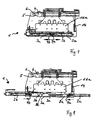
- the robot carrying the device according to the invention lowers it above the stack, so that the roller 9a, 9b come to lie in the lower region of the uppermost layer or of the upper container. They are then moved together with the support plates 2a, 2b against the container. Then they sit in opposite directions and lift the container until it reaches the upper area of the rollers 9a, 9b with its lower edge, whereupon they can travel under the container together with the support plates, as shown in FIGS Fig. 5 . 6 and 7 is shown. After the container has been reliably engaged by the support plates 2a, 2b, the robot can lift it off the stack by means of the inventive device 1 connected to it and move it to a place of deposition.
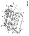
- FIG. 9 shown perspective view of a device according to the invention are side parts of the base frame 1 is not shown, so that the interior is visible.
- the support base parts 2a, 2b are in a position moved away from each other to the outside, so that it is possible to receive a bundle of charges 22 which projects into the interior of the device.
- a plate-shaped hold-down 21 is arranged, which adapts flexibly to the surface of the container and by which a slipping or tilting of loosely positioned on the top objects, such as covers or cover layers is reliably avoided.
- the hold-down 21 has a rectangular shape, which substantially corresponds to the base surface, which is formed by the support base parts 2 a, 2 b in the contracted state. Such a complete covering of the top of the respective recorded pack layer is possible.
- a headband 23a, 23b, 23c, 23d via which the hold-down 21 by means of one attachment 24a, 24b, 24c, 24d respectively to one of four linear guides 25a, 25b, 25c, 25d coupled is.
- the linear guides 25a, 25b, 25c, 25d are essentially formed by rails which are arranged at the respective side edges of the device according to the invention and extend perpendicular to the surface of the hold-down device.
- Such a stepless, electrically or pneumatically driven lowering or lifting the hold-21 on or from the top of the bundle stack is possible.
- the use of the hold-21 can be done as needed. For example, a lowering of the blank holder 21 on the top of the bundle stack 22 may be provided only if loose material is present, through which the loading or unloading process could be affected or disturbed.
- the device according to the invention is positioned over the topmost package layer.
- the lower holder 21 is lowered onto the upper side of the container unit 22.
- the uppermost layer of containers is lifted by the rollers 9a, 9b in the manner described above, so that it is possible for the containers to pass under the support plates 2a, 2b is.
- loosely positioned objects such as covers or cover layers, are fixed or held in place by the hold-down positioned at the top.
- the position in the device according to the invention is recorded by the robot, which in turn carries out a repositioning of the same, for example, on another pallet or a derailleur table. Even during the step of dispensing the pack layer, the hold-down remains in position on the top the pack layer and returns only after the delivery process of the pack layer back to its upper starting position.
Claims (25)
- Procédé pour dépaléttiser des emballages secondaires empilés au moyen d'un dispositif selon la revendication 3, dans lequel des emballages secondaires sont soulevés par friction et au moins un plateau de support est amené sous ceux-ci, dans lequel les emballages secondaires sont soulevés par deux côtés situés en vis-à-vis l'un de l'autre selon une orientation parallèle aux couches d'emballages, en particulier perpendiculairement, en ce que des rouleaux sont en prise par friction au niveau des côtés situés en vis-à-vis, dans lequel deux parties de plateau de support du plateau de support sont amenées par deux côtés situés en vis-à-vis sous les emballages secondaires soulevés, et dans lequel, pour prélever un emballage secondaire supérieur d'une pile d'emballages secondaires, un robot portant le dispositif abaissant ce dernier sur la pile de manière à ce que les rouleaux arrivent à reposer dans la partie inférieure de la couche supérieure ou de l'emballage secondaire supérieur, les rouleaux étant alors déplacés ensemble avec les parties de plateau de support contre l'emballage, se mettant ensuite en mouvement en sens contraire et soulevant l'emballage secondaire par force jusqu'à ce que celui-ci arrive avec son bord inférieur dans la zone supérieure des rouleaux, après quoi ceux-ci passent ensemble avec les parties de plateau de support sous l'emballage secondaire et le robot soulevant l'emballage secondaire saisi par le dessous grâce aux parties de plateau de support au moyen du dispositif qui est relié à lui, et le déplaçant vers un emplacement de dépôt.
- Procédé selon la revendication 1, caractérisé en ce qu'au moins un serre-flan (21) exerce une pression sur la face supérieure du lot (22).
- Dispositif pour dépaléttiser des emballages secondaires empilés, avec au moins un rouleau pour soulever les emballages secondaires et avec un plateau de support,
caractérisé en ce que le plateau de support présente au moins deux parties de plateau de support (2a, 2b) déplaçables l'une par rapport à l'autre, dans lequel des rouleaux (9a, 9b) situés en vis-à-vis l'un de l'autre sont montés de manière rotative sur des bords longitudinaux intérieurs tournés l'un vers l'autre des parties de plateau de support pour soulever par friction des emballages secondaires selon une orientation parallèle aux couches d'emballages secondaires, en particulier perpendiculairement, et en ce que le dispositif présente un dispositif d'accouplement de raccordement (20) pour relier le dispositif à un robot, dans lequel les rouleaux (9a, 9b) peuvent être entraînés par au moins un moteur d'entraînement de rouleaux (11a, 11b). - Dispositif selon la revendication 3, caractérisé en ce que les rouleaux peuvent être entraînés au-dessus des courroies (10a, 9b) par au moins un monteur (11a, 11b).
- Dispositif selon une des revendications 3 à 4, caractérisé en ce que les deux parties du plateau porteur (2a, 2b) peuvent se déplacer sous l'action de tocs d'entraînement (8a, 8b).
- Dispositif selon une des revendications 3 à 5, caractérisé en ce que les deux parties du plateau porteur (2a, 2b) peuvent se déplacer au moyen de courroies d'entraînement (7a, 7b), le cas échéant par l'intermédiaire de tocs d'entraînement (8, 8a).
- Dispositif selon une des revendications 3 à 6, caractérisé en ce que les deux parties du plateau porteur (2a, 2b) peuvent se déplacer par l'intermédiaire d'au moins un arbre distributeur (6).
- Dispositif selon la revendication 7, caractérisé en ce que l'arbre distributeur (6) peut être entraîné par au moins un moteur (4) par l'intermédiaire d'au moins une courroie crantée (5).
- Dispositif selon une des revendications 3 à 8, caractérisé par une butée fixe (13) et une butée mobile (14) placée en face pour positionner le lot.
- Dispositif selon la revendication 9, caractérisé en ce que la butée mobile (14) se déplace sous l'effet d'au moins un vérin, de préférence un vérin à air comprimé.
- Dispositif selon une des revendications 3 à 9, caractérisé par au moins une plaque coulissante (16a, 16b) se déplaçant parallèlement au sens de l'étendue sous l'effet de deux rouleaux (9a, 9b) pour centrer les lots.
- Dispositif selon la revendication 11, caractérisé par deux plaques coulissantes (16a, 16b) se déplaçant l'une vers l'autre.
- Dispositif selon la revendication 12, caractérisé en ce que les plaques coulissantes (16a, 16b) peuvent être déplacées par au moins un moteur de centrage, de préférence par l'intermédiaire de courroies crantées.
- Dispositif selon la revendication 3, caractérisé en ce que les plaques coulissantes (16a, 16b) peuvent être déplacées de manière synchrone.
- Dispositif selon une des revendications 3 à 14, caractérisé par un serre-flan (21) disposé sur la face supérieure du lot (22).
- Dispositif selon la revendication 15, caractérisé en ce que le serre-flan (21) est de forme essentiellement plane.
- Dispositif selon une des revendications 15 ou 16, caractérisé en ce que le serre-flan (21) est suffisamment flexible pour pouvoir épouser pour l'essentiel la forme de la surface des lots (22).
- Dispositif selon la revendication 17, caractérisé en ce que le serre-flan (21) est formé d'un matériel chaîné, singulièrement de chaînes plates à charnières en plastique ou en métal.
- Dispositif selon la revendication 17, caractérisé en ce que le serre-flan (21) est formé d'un matériel tressé sous forme de tapis, singulièrement du fil métallique ou de l'étoffe.
- Dispositif selon une des revendications 15 ou 16, caractérisé en ce que le serre-flan (21) est réalisé de façon rigide.
- Dispositif selon une des revendications 15 à 20, caractérisé en ce que le serre-flan (21) peut être déplacé verticalement d'une position supérieure à une position inférieure.
- Dispositif selon la revendication 21, caractérisé en ce que le serre-flan (21) peut être déplacé en continu.
- Dispositif selon une des revendications 21 ou 22, caractérisé en ce que la position inférieure correspond à la position dans laquelle le serre-flan (21) entre en contact par adhérence avec la surface de la face supérieure du lot (22).
- Dispositif selon une des revendications 21 à 23, caractérisé en ce que le serre-flan (21) peut être déplacé par action pneumatique et/ou sous l'laction d'un monteur.
- Dispositif selon une des revendications 15 à 24, caractérisé en ce que le serre-flan (21) est formé pour couvrir sur la face supérieure totale du lot (22).
Applications Claiming Priority (2)
| Application Number | Priority Date | Filing Date | Title |
|---|---|---|---|
| DE102006022155A DE102006022155A1 (de) | 2006-05-12 | 2006-05-12 | Verfahren und Vorrichtung zum Entpalletieren von gestapelten Gebinden |
| PCT/EP2007/004052 WO2007131668A1 (fr) | 2006-05-12 | 2007-05-08 | Procédé et dispositif permettant de prélever des emballages secondaires empilés sur une palette |
Publications (3)
| Publication Number | Publication Date |
|---|---|
| EP1890954A1 EP1890954A1 (fr) | 2008-02-27 |
| EP1890954B1 EP1890954B1 (fr) | 2009-03-04 |
| EP1890954B2 true EP1890954B2 (fr) | 2016-10-12 |
Family
ID=38460585
Family Applications (1)
| Application Number | Title | Priority Date | Filing Date |
|---|---|---|---|
| EP07724976.1A Active EP1890954B2 (fr) | 2006-05-12 | 2007-05-08 | Procédé et dispositif permettant de prélever des emballages secondaires empilés sur une palette |
Country Status (8)
| Country | Link |
|---|---|
| US (1) | US8915696B2 (fr) |
| EP (1) | EP1890954B2 (fr) |
| JP (1) | JP5170784B2 (fr) |
| AT (1) | ATE424362T1 (fr) |
| CA (1) | CA2651886A1 (fr) |
| DE (2) | DE102006022155A1 (fr) |
| ES (1) | ES2323907T5 (fr) |
| WO (1) | WO2007131668A1 (fr) |
Families Citing this family (18)
| Publication number | Priority date | Publication date | Assignee | Title |
|---|---|---|---|---|
| US9592970B2 (en) * | 2008-07-17 | 2017-03-14 | Toby D. Henderson | Robotic gantry with end effector for product lifting |
| DE102008035330A1 (de) | 2008-07-29 | 2010-02-04 | Krones Ag | Vorrichtung zum Kommissionieren und/oder Umschichten mehrerer palettierter Gebinde |
| EP2401217B1 (fr) * | 2009-02-27 | 2013-09-18 | Univeyor A/S | Appareil de manutention de couches de marchandises palettisées |
| DE102009011301B4 (de) | 2009-03-02 | 2020-11-26 | Kuka Roboter Gmbh | Verfahren und Greifer zur Handhabung eines Gebindes mittels eines Manipulators |
| DE102009011299B4 (de) * | 2009-03-02 | 2020-11-05 | Kuka Roboter Gmbh | Verfahren und Manipulatorgreifer zur Beabstandung von Gebinden einer Gebindelage |
| DE102009025942A1 (de) | 2009-06-09 | 2011-01-13 | Krones Ag | Vorrichtung und Verfahren zur Handhabung von Artikel- und/oder Gebindelagen |
| ITMI20110693A1 (it) * | 2011-04-22 | 2012-10-23 | Emmeti Spa | Macchina per la movimentazione di strati sovrapposti di oggetti e relativo metodo |
| PL2794439T3 (pl) * | 2011-12-20 | 2016-11-30 | System depaletyzacji i zespół do zdejmowania | |
| DE102012204027A1 (de) * | 2012-03-14 | 2013-09-19 | Krones Ag | Transfereinheit zur horizontalen Verschiebung von Artikellagen zwischen benachbarten Modulen |
| DE102012009649B4 (de) | 2012-05-14 | 2016-05-12 | Fraunhofer-Gesellschaft zur Förderung der angewandten Forschung e.V. | Greifvorrichtung |
| DE102013101119A1 (de) | 2013-02-05 | 2014-08-21 | Krones Aktiengesellschaft | Jalousieverschluss und hiermit ausgestatteter Palettier- oder Jalousiekopf zum Umgang mit Artikeln |
| EP2923975B1 (fr) * | 2014-03-26 | 2020-02-05 | Segbert GmbH & Co. KG | Dispositif et procédé de dépalettisation pour le prélèvement de couches à partir de paquets d'une pile de marchandises |
| CA2892342C (fr) | 2014-05-22 | 2016-11-01 | Sylvain-Paul Morency | Outil et methode de depalletisation de couche |
| CN105569584B (zh) * | 2015-03-27 | 2017-02-08 | 中国石油化工股份有限公司 | 油管自动化排放装置及方法 |
| IT201700101384A1 (it) * | 2017-09-11 | 2019-03-11 | Ocme Srl | Dispositivo di presa strato a strisciamento e relativo metodo di trasferimento di strati. |
| US11161691B2 (en) * | 2018-02-02 | 2021-11-02 | Amazon Technologies, Inc. | Container palletizing system |
| US11414279B2 (en) * | 2019-08-02 | 2022-08-16 | Robogistics LLC | High-speed multi-purpose mix load robotic end-of-arm tooling and method of using same |
| DE102019008281B3 (de) * | 2019-11-28 | 2020-12-10 | Kuka Deutschland Gmbh | Greifer und Entladestation |
Citations (6)
| Publication number | Priority date | Publication date | Assignee | Title |
|---|---|---|---|---|
| US3917082A (en) † | 1972-10-24 | 1975-11-04 | Wyard Ind Inc | Destacking apparatus |
| DE3915139A1 (de) † | 1989-05-09 | 1990-11-15 | Focke & Co | Verfahren und anlage zum umordnen von sortenweise palettierten gegenstaenden zu gruppen bestimmter sortenzusammenstellung |
| EP0462518A1 (fr) † | 1990-06-20 | 1991-12-27 | Digitron AG | Procédé et dispositif pour enlever et/ou déposer des articles sous la forme de paquets |
| US5265712A (en) † | 1991-12-23 | 1993-11-30 | Digitron Ag | Method and apparatus for taking up articles |
| EP0627373A1 (fr) † | 1993-06-01 | 1994-12-07 | Digitron AG | Procédé et dispositif pour saisir des objets |
| DE19700911A1 (de) † | 1997-01-14 | 1998-07-16 | Mansfeld Maschinen Und Anlagen | Anordnung zur Depalettierung und Palettierung |
Family Cites Families (29)
| Publication number | Priority date | Publication date | Assignee | Title |
|---|---|---|---|---|
| US3070241A (en) * | 1959-08-24 | 1962-12-25 | Alvey Conveyor Mfg Company | Machine for unstacking palletized loads |
| US3263829A (en) * | 1963-10-28 | 1966-08-02 | Fmc Corp | Article handling apparatus |
| GB1276070A (en) * | 1970-11-19 | 1972-06-01 | Yamashita Tekko Kabushiki Kais | Unloading machine |
| DE7539313U (de) * | 1975-12-10 | 1976-04-29 | Enzinger-Union-Werke Ag, 6800 Mannheim | Entpalettiervorrichtung mit einem flexiblen stabrost |
| DE2945883A1 (de) * | 1979-11-14 | 1981-05-27 | Holstein Und Kappert Gmbh, 4600 Dortmund | Vorrichtung zum beladen von paletten mit stueckguetern |
| US4453874A (en) * | 1982-12-22 | 1984-06-12 | Internationale Octrooi Maatschappij "Octropa" Bv | Article-handling apparatus |
| JPS60178122A (ja) * | 1984-02-23 | 1985-09-12 | Okura Yusoki Co Ltd | パレツト荷積み装置 |
| DE3762230D1 (de) * | 1986-08-16 | 1990-05-17 | Meypack Verpackungs Und Palett | Sackpalettierer. |
| CH671566A5 (fr) * | 1986-09-26 | 1989-09-15 | Oskar Roth | |
| DE3718601A1 (de) | 1987-06-03 | 1988-12-22 | Bat Cigarettenfab Gmbh | Vorrichtung zum abheben mindestens eines material-stapels |
| GB8924222D0 (en) * | 1989-10-27 | 1989-12-13 | Squires Michael | Load handling apparatus |
| US5082319A (en) * | 1990-01-11 | 1992-01-21 | Fmc Corporation | Layer clamp hand with floating side clamps and carton flap hold-down platen |
| DE4128809A1 (de) * | 1991-08-30 | 1993-03-04 | Khs Verpackungstechnik Gmbh | Vorrichtung zum entladen von paletten |
| DE4206038C2 (de) * | 1992-02-27 | 1994-08-18 | Khs Verpackungstechnik Gmbh | Vorrichtung und Vorrichtung zum Auflösen und Bilden von Stückgutstapeln |
| JPH0645945U (ja) * | 1992-11-24 | 1994-06-24 | 株式会社タイガーマシン製作所 | 製品の段降し装置 |
| DE4317283C1 (de) * | 1993-05-25 | 1994-09-22 | Kisters Maschinenbau Gmbh | Handhabungsgerät, insbesondere Greifer, zum Anschluß an den Arm eines Industrieroboters |
| FR2754803B1 (fr) | 1996-10-17 | 1999-02-12 | Imetal Services Materiaux | Dispositif d'empilage et de depilage de supports de pieces |
| IT1292888B1 (it) * | 1997-04-29 | 1999-02-11 | Selco Spa | Impianto per il trasferimento di corpi piani. |
| JPH10338354A (ja) * | 1997-06-06 | 1998-12-22 | Seibu Electric & Mach Co Ltd | 荷卸し方法及びその装置 |
| US6164900A (en) * | 1997-08-29 | 2000-12-26 | Westfalia Technologies, Inc. | System and method for palletizing packages |
| US5868549A (en) * | 1997-08-29 | 1999-02-09 | Hk Systems, Inc. | Palletizer with air assisted slide plate assembly and indexing pallet hoist |
| JP2000052287A (ja) * | 1998-08-10 | 2000-02-22 | Ishii Ind Co Ltd | 長尺物積載装置 |
| JP2001072244A (ja) * | 1999-09-08 | 2001-03-21 | Daifuku Co Ltd | 荷卸し装置および荷卸し方法 |
| US6746203B2 (en) * | 2001-03-30 | 2004-06-08 | Axium, Inc. | Gripping and transport clamp mounted at the end of a robotic arm and method for operating the same |
| JP4045503B2 (ja) * | 2003-07-17 | 2008-02-13 | 株式会社ダイフク | 物品把持装置 |
| AU2004293242B2 (en) * | 2003-10-28 | 2011-02-24 | Aew Delford Systems Limited | Improved pick and place gripper |
| FR2870822B1 (fr) * | 2004-05-28 | 2006-08-25 | Materiel Arboriculture | Machine de palettisation d'objets tels que des caisses d'emballage |
| ITRE20040119A1 (it) * | 2004-10-01 | 2005-01-01 | Tecnoform S R L | Unita' di movimentazione per la pallettizzazione |
| DE102008023770A1 (de) * | 2007-09-13 | 2009-03-19 | Multivac Sepp Haggenmüller Gmbh & Co. Kg | Vorrichtung zur Aufnahme und zum Transport eines Gutes |
-
2006
- 2006-05-12 DE DE102006022155A patent/DE102006022155A1/de not_active Withdrawn
-
2007
- 2007-05-08 ES ES07724976.1T patent/ES2323907T5/es active Active
- 2007-05-08 US US12/298,678 patent/US8915696B2/en not_active Expired - Fee Related
- 2007-05-08 WO PCT/EP2007/004052 patent/WO2007131668A1/fr active Application Filing
- 2007-05-08 CA CA002651886A patent/CA2651886A1/fr not_active Abandoned
- 2007-05-08 JP JP2009508241A patent/JP5170784B2/ja not_active Expired - Fee Related
- 2007-05-08 DE DE502007000478T patent/DE502007000478D1/de active Active
- 2007-05-08 AT AT07724976T patent/ATE424362T1/de active
- 2007-05-08 EP EP07724976.1A patent/EP1890954B2/fr active Active
Patent Citations (6)
| Publication number | Priority date | Publication date | Assignee | Title |
|---|---|---|---|---|
| US3917082A (en) † | 1972-10-24 | 1975-11-04 | Wyard Ind Inc | Destacking apparatus |
| DE3915139A1 (de) † | 1989-05-09 | 1990-11-15 | Focke & Co | Verfahren und anlage zum umordnen von sortenweise palettierten gegenstaenden zu gruppen bestimmter sortenzusammenstellung |
| EP0462518A1 (fr) † | 1990-06-20 | 1991-12-27 | Digitron AG | Procédé et dispositif pour enlever et/ou déposer des articles sous la forme de paquets |
| US5265712A (en) † | 1991-12-23 | 1993-11-30 | Digitron Ag | Method and apparatus for taking up articles |
| EP0627373A1 (fr) † | 1993-06-01 | 1994-12-07 | Digitron AG | Procédé et dispositif pour saisir des objets |
| DE19700911A1 (de) † | 1997-01-14 | 1998-07-16 | Mansfeld Maschinen Und Anlagen | Anordnung zur Depalettierung und Palettierung |
Also Published As
| Publication number | Publication date |
|---|---|
| US8915696B2 (en) | 2014-12-23 |
| WO2007131668A1 (fr) | 2007-11-22 |
| EP1890954B1 (fr) | 2009-03-04 |
| ES2323907T5 (es) | 2017-04-28 |
| JP5170784B2 (ja) | 2013-03-27 |
| ATE424362T1 (de) | 2009-03-15 |
| DE102006022155A1 (de) | 2007-12-06 |
| DE502007000478D1 (de) | 2009-04-16 |
| JP2009536907A (ja) | 2009-10-22 |
| US20090148266A1 (en) | 2009-06-11 |
| CA2651886A1 (fr) | 2007-11-22 |
| ES2323907T3 (es) | 2009-07-27 |
| EP1890954A1 (fr) | 2008-02-27 |
Similar Documents
| Publication | Publication Date | Title |
|---|---|---|
| EP1890954B2 (fr) | Procédé et dispositif permettant de prélever des emballages secondaires empilés sur une palette | |
| EP2794439B1 (fr) | Système de dépalettisation et unité de prélèvement | |
| EP2046668B1 (fr) | Dispositif de transport pour dépalétiser des marchandises empilées sur un support de marchandises | |
| DE3506360C2 (fr) | ||
| DE102007046919B4 (de) | Greifer zum automatischen Ergreifen von Packeinheiten | |
| EP1908709B1 (fr) | Procédé et dispositif destinés à la réception et au repositionnement de récipients | |
| EP1462394B1 (fr) | Dispositif de chargement pour porte-charges | |
| EP0431346B1 (fr) | Procédé de chargement et déchargement de palettes avec piles de produits en nappe et dispositif pour cela | |
| EP1921030B1 (fr) | Transpalette doté d'un élément de retenue | |
| AT522558A2 (de) | Depalettieranordnung mit einer Vorrichtung zum Depalettieren von stapelbaren Stückgutgebinden und Verfahren zum Depalettieren von stapelbaren Stückgutgebinden | |
| EP0742166B1 (fr) | Procédé et dispositif de dépalletisation | |
| EP0482406A1 (fr) | Dispositif de maniement pour articles tels que cartons | |
| EP2303736B1 (fr) | Dispositif pour charger et/ou regrouper des groupes de recipients sur palettes | |
| WO2016156220A1 (fr) | Installation de palettisation et procédé de palettisation mécanique d'objets | |
| DE102009011301B4 (de) | Verfahren und Greifer zur Handhabung eines Gebindes mittels eines Manipulators | |
| EP1851144B1 (fr) | Dispositif de rotation | |
| EP2243732B1 (fr) | Dispositif et procédé destinés à transférer des gerbes ou des couches d'articles dans une station de chargement | |
| DE102011100968B4 (de) | Verfahren und Vorrichtung zum Ausrichten einer Palette | |
| DE102006038089B4 (de) | Kistenstapler | |
| DE3210189A1 (de) | Anordnung zum uebergeben einer sacklage | |
| WO2001010755A1 (fr) | Dispositif pour transferer des marchandises transportees, d'un convoyeur sur au moins un autre convoyeur | |
| DE102009052551A1 (de) | Verfahren und Vorrichtung zum Herstellen einer Verpackungseinheit | |
| DE102009040792A1 (de) | Palettenentstapler | |
| DE102022103519A1 (de) | Verfahren und Vorrichtung zum automatischen mehrlagigen Bestapeln eines Trägers mit Packstücken | |
| EP1445221B1 (fr) | Dispositif et procédé pour changer des palettes |
Legal Events
| Date | Code | Title | Description |
|---|---|---|---|
| PUAI | Public reference made under article 153(3) epc to a published international application that has entered the european phase |
Free format text: ORIGINAL CODE: 0009012 |
|
| 17P | Request for examination filed |
Effective date: 20071011 |
|
| AK | Designated contracting states |
Kind code of ref document: A1 Designated state(s): AT BE BG CH CY CZ DE DK EE ES FI FR GB GR HU IE IS IT LI LT LU LV MC MT NL PL PT RO SE SI SK TR |
|
| AX | Request for extension of the european patent |
Extension state: AL BA HR MK YU |
|
| RAX | Requested extension states of the european patent have changed |
Extension state: HR Extension state: MK Extension state: BA Extension state: RS Extension state: AL |
|
| GRAP | Despatch of communication of intention to grant a patent |
Free format text: ORIGINAL CODE: EPIDOSNIGR1 |
|
| GRAS | Grant fee paid |
Free format text: ORIGINAL CODE: EPIDOSNIGR3 |
|
| GRAA | (expected) grant |
Free format text: ORIGINAL CODE: 0009210 |
|
| AK | Designated contracting states |
Kind code of ref document: B1 Designated state(s): AT BE BG CH CY CZ DE DK EE ES FI FR GB GR HU IE IS IT LI LT LU LV MC MT NL PL PT RO SE SI SK TR |
|
| REG | Reference to a national code |
Ref country code: GB Ref legal event code: FG4D Free format text: NOT ENGLISH |
|
| REG | Reference to a national code |
Ref country code: CH Ref legal event code: EP |
|
| REG | Reference to a national code |
Ref country code: IE Ref legal event code: FG4D Free format text: LANGUAGE OF EP DOCUMENT: GERMAN |
|
| REF | Corresponds to: |
Ref document number: 502007000478 Country of ref document: DE Date of ref document: 20090416 Kind code of ref document: P |
|
| REG | Reference to a national code |
Ref country code: ES Ref legal event code: FG2A Ref document number: 2323907 Country of ref document: ES Kind code of ref document: T3 |
|
| PG25 | Lapsed in a contracting state [announced via postgrant information from national office to epo] |
Ref country code: SI Free format text: LAPSE BECAUSE OF FAILURE TO SUBMIT A TRANSLATION OF THE DESCRIPTION OR TO PAY THE FEE WITHIN THE PRESCRIBED TIME-LIMIT Effective date: 20090304 Ref country code: FI Free format text: LAPSE BECAUSE OF FAILURE TO SUBMIT A TRANSLATION OF THE DESCRIPTION OR TO PAY THE FEE WITHIN THE PRESCRIBED TIME-LIMIT Effective date: 20090304 Ref country code: LT Free format text: LAPSE BECAUSE OF FAILURE TO SUBMIT A TRANSLATION OF THE DESCRIPTION OR TO PAY THE FEE WITHIN THE PRESCRIBED TIME-LIMIT Effective date: 20090304 |
|
| PG25 | Lapsed in a contracting state [announced via postgrant information from national office to epo] |
Ref country code: LV Free format text: LAPSE BECAUSE OF FAILURE TO SUBMIT A TRANSLATION OF THE DESCRIPTION OR TO PAY THE FEE WITHIN THE PRESCRIBED TIME-LIMIT Effective date: 20090304 Ref country code: PL Free format text: LAPSE BECAUSE OF FAILURE TO SUBMIT A TRANSLATION OF THE DESCRIPTION OR TO PAY THE FEE WITHIN THE PRESCRIBED TIME-LIMIT Effective date: 20090304 Ref country code: SE Free format text: LAPSE BECAUSE OF FAILURE TO SUBMIT A TRANSLATION OF THE DESCRIPTION OR TO PAY THE FEE WITHIN THE PRESCRIBED TIME-LIMIT Effective date: 20090604 |
|
| REG | Reference to a national code |
Ref country code: IE Ref legal event code: FD4D |
|
| PG25 | Lapsed in a contracting state [announced via postgrant information from national office to epo] |
Ref country code: PT Free format text: LAPSE BECAUSE OF FAILURE TO SUBMIT A TRANSLATION OF THE DESCRIPTION OR TO PAY THE FEE WITHIN THE PRESCRIBED TIME-LIMIT Effective date: 20090818 Ref country code: EE Free format text: LAPSE BECAUSE OF FAILURE TO SUBMIT A TRANSLATION OF THE DESCRIPTION OR TO PAY THE FEE WITHIN THE PRESCRIBED TIME-LIMIT Effective date: 20090304 Ref country code: IE Free format text: LAPSE BECAUSE OF FAILURE TO SUBMIT A TRANSLATION OF THE DESCRIPTION OR TO PAY THE FEE WITHIN THE PRESCRIBED TIME-LIMIT Effective date: 20090304 Ref country code: CZ Free format text: LAPSE BECAUSE OF FAILURE TO SUBMIT A TRANSLATION OF THE DESCRIPTION OR TO PAY THE FEE WITHIN THE PRESCRIBED TIME-LIMIT Effective date: 20090304 |
|
| PLBI | Opposition filed |
Free format text: ORIGINAL CODE: 0009260 |
|
| PG25 | Lapsed in a contracting state [announced via postgrant information from national office to epo] |
Ref country code: RO Free format text: LAPSE BECAUSE OF FAILURE TO SUBMIT A TRANSLATION OF THE DESCRIPTION OR TO PAY THE FEE WITHIN THE PRESCRIBED TIME-LIMIT Effective date: 20090304 Ref country code: SK Free format text: LAPSE BECAUSE OF FAILURE TO SUBMIT A TRANSLATION OF THE DESCRIPTION OR TO PAY THE FEE WITHIN THE PRESCRIBED TIME-LIMIT Effective date: 20090304 Ref country code: IS Free format text: LAPSE BECAUSE OF FAILURE TO SUBMIT A TRANSLATION OF THE DESCRIPTION OR TO PAY THE FEE WITHIN THE PRESCRIBED TIME-LIMIT Effective date: 20090704 |
|
| 26 | Opposition filed |
Opponent name: KRONES AG Effective date: 20091104 |
|
| PG25 | Lapsed in a contracting state [announced via postgrant information from national office to epo] |
Ref country code: MC Free format text: LAPSE BECAUSE OF NON-PAYMENT OF DUE FEES Effective date: 20090531 |
|
| PLAX | Notice of opposition and request to file observation + time limit sent |
Free format text: ORIGINAL CODE: EPIDOSNOBS2 |
|
| PLAF | Information modified related to communication of a notice of opposition and request to file observations + time limit |
Free format text: ORIGINAL CODE: EPIDOSCOBS2 |
|
| PG25 | Lapsed in a contracting state [announced via postgrant information from national office to epo] |
Ref country code: DK Free format text: LAPSE BECAUSE OF FAILURE TO SUBMIT A TRANSLATION OF THE DESCRIPTION OR TO PAY THE FEE WITHIN THE PRESCRIBED TIME-LIMIT Effective date: 20090304 Ref country code: BG Free format text: LAPSE BECAUSE OF FAILURE TO SUBMIT A TRANSLATION OF THE DESCRIPTION OR TO PAY THE FEE WITHIN THE PRESCRIBED TIME-LIMIT Effective date: 20090604 |
|
| NLR1 | Nl: opposition has been filed with the epo |
Opponent name: KRONES AG |
|
| PLBB | Reply of patent proprietor to notice(s) of opposition received |
Free format text: ORIGINAL CODE: EPIDOSNOBS3 |
|
| PLAY | Examination report in opposition despatched + time limit |
Free format text: ORIGINAL CODE: EPIDOSNORE2 |
|
| PG25 | Lapsed in a contracting state [announced via postgrant information from national office to epo] |
Ref country code: GR Free format text: LAPSE BECAUSE OF FAILURE TO SUBMIT A TRANSLATION OF THE DESCRIPTION OR TO PAY THE FEE WITHIN THE PRESCRIBED TIME-LIMIT Effective date: 20090605 |
|
| PLBC | Reply to examination report in opposition received |
Free format text: ORIGINAL CODE: EPIDOSNORE3 |
|
| PG25 | Lapsed in a contracting state [announced via postgrant information from national office to epo] |
Ref country code: IT Free format text: LAPSE BECAUSE OF FAILURE TO SUBMIT A TRANSLATION OF THE DESCRIPTION OR TO PAY THE FEE WITHIN THE PRESCRIBED TIME-LIMIT Effective date: 20090304 |
|
| PG25 | Lapsed in a contracting state [announced via postgrant information from national office to epo] |
Ref country code: LU Free format text: LAPSE BECAUSE OF NON-PAYMENT OF DUE FEES Effective date: 20090508 |
|
| PG25 | Lapsed in a contracting state [announced via postgrant information from national office to epo] |
Ref country code: HU Free format text: LAPSE BECAUSE OF FAILURE TO SUBMIT A TRANSLATION OF THE DESCRIPTION OR TO PAY THE FEE WITHIN THE PRESCRIBED TIME-LIMIT Effective date: 20090905 |
|
| PG25 | Lapsed in a contracting state [announced via postgrant information from national office to epo] |
Ref country code: TR Free format text: LAPSE BECAUSE OF FAILURE TO SUBMIT A TRANSLATION OF THE DESCRIPTION OR TO PAY THE FEE WITHIN THE PRESCRIBED TIME-LIMIT Effective date: 20090304 |
|
| PG25 | Lapsed in a contracting state [announced via postgrant information from national office to epo] |
Ref country code: CY Free format text: LAPSE BECAUSE OF FAILURE TO SUBMIT A TRANSLATION OF THE DESCRIPTION OR TO PAY THE FEE WITHIN THE PRESCRIBED TIME-LIMIT Effective date: 20090304 |
|
| REG | Reference to a national code |
Ref country code: CH Ref legal event code: PL |
|
| APBM | Appeal reference recorded |
Free format text: ORIGINAL CODE: EPIDOSNREFNO |
|
| APBP | Date of receipt of notice of appeal recorded |
Free format text: ORIGINAL CODE: EPIDOSNNOA2O |
|
| APAH | Appeal reference modified |
Free format text: ORIGINAL CODE: EPIDOSCREFNO |
|
| PG25 | Lapsed in a contracting state [announced via postgrant information from national office to epo] |
Ref country code: CH Free format text: LAPSE BECAUSE OF NON-PAYMENT OF DUE FEES Effective date: 20110531 Ref country code: LI Free format text: LAPSE BECAUSE OF NON-PAYMENT OF DUE FEES Effective date: 20110531 |
|
| APBQ | Date of receipt of statement of grounds of appeal recorded |
Free format text: ORIGINAL CODE: EPIDOSNNOA3O |
|
| REG | Reference to a national code |
Ref country code: DE Ref legal event code: R082 Ref document number: 502007000478 Country of ref document: DE |
|
| APBU | Appeal procedure closed |
Free format text: ORIGINAL CODE: EPIDOSNNOA9O |
|
| REG | Reference to a national code |
Ref country code: FR Ref legal event code: PLFP Year of fee payment: 10 |
|
| PUAH | Patent maintained in amended form |
Free format text: ORIGINAL CODE: 0009272 |
|
| STAA | Information on the status of an ep patent application or granted ep patent |
Free format text: STATUS: PATENT MAINTAINED AS AMENDED |
|
| 27A | Patent maintained in amended form |
Effective date: 20161012 |
|
| AK | Designated contracting states |
Kind code of ref document: B2 Designated state(s): AT BE BG CH CY CZ DE DK EE ES FI FR GB GR HU IE IS IT LI LT LU LV MC MT NL PL PT RO SE SI SK TR |
|
| REG | Reference to a national code |
Ref country code: DE Ref legal event code: R102 Ref document number: 502007000478 Country of ref document: DE |
|
| REG | Reference to a national code |
Ref country code: NL Ref legal event code: FP |
|
| PG25 | Lapsed in a contracting state [announced via postgrant information from national office to epo] |
Ref country code: LV Free format text: LAPSE BECAUSE OF FAILURE TO SUBMIT A TRANSLATION OF THE DESCRIPTION OR TO PAY THE FEE WITHIN THE PRESCRIBED TIME-LIMIT Effective date: 20161012 |
|
| REG | Reference to a national code |
Ref country code: FR Ref legal event code: PLFP Year of fee payment: 11 |
|
| REG | Reference to a national code |
Ref country code: ES Ref legal event code: DC2A Ref document number: 2323907 Country of ref document: ES Kind code of ref document: T5 Effective date: 20170428 |
|
| REG | Reference to a national code |
Ref country code: FR Ref legal event code: PLFP Year of fee payment: 12 |
|
| REG | Reference to a national code |
Ref country code: DE Ref legal event code: R081 Ref document number: 502007000478 Country of ref document: DE Owner name: KUKA DEUTSCHLAND GMBH, DE Free format text: FORMER OWNER: KUKA ROBOTER GMBH, 86165 AUGSBURG, DE |
|
| PGFP | Annual fee paid to national office [announced via postgrant information from national office to epo] |
Ref country code: FR Payment date: 20200414 Year of fee payment: 14 Ref country code: ES Payment date: 20200601 Year of fee payment: 14 Ref country code: NL Payment date: 20200513 Year of fee payment: 14 Ref country code: DE Payment date: 20200428 Year of fee payment: 14 |
|
| PGFP | Annual fee paid to national office [announced via postgrant information from national office to epo] |
Ref country code: GB Payment date: 20200429 Year of fee payment: 14 Ref country code: BE Payment date: 20200416 Year of fee payment: 14 |
|
| PGFP | Annual fee paid to national office [announced via postgrant information from national office to epo] |
Ref country code: AT Payment date: 20200428 Year of fee payment: 14 |
|
| REG | Reference to a national code |
Ref country code: DE Ref legal event code: R119 Ref document number: 502007000478 Country of ref document: DE |
|
| REG | Reference to a national code |
Ref country code: NL Ref legal event code: MM Effective date: 20210601 |
|
| REG | Reference to a national code |
Ref country code: AT Ref legal event code: MM01 Ref document number: 424362 Country of ref document: AT Kind code of ref document: T Effective date: 20210508 |
|
| GBPC | Gb: european patent ceased through non-payment of renewal fee |
Effective date: 20210508 |
|
| PG25 | Lapsed in a contracting state [announced via postgrant information from national office to epo] |
Ref country code: AT Free format text: LAPSE BECAUSE OF NON-PAYMENT OF DUE FEES Effective date: 20210508 |
|
| REG | Reference to a national code |
Ref country code: BE Ref legal event code: MM Effective date: 20210531 |
|
| PG25 | Lapsed in a contracting state [announced via postgrant information from national office to epo] |
Ref country code: GB Free format text: LAPSE BECAUSE OF NON-PAYMENT OF DUE FEES Effective date: 20210508 Ref country code: DE Free format text: LAPSE BECAUSE OF NON-PAYMENT OF DUE FEES Effective date: 20211201 |
|
| PG25 | Lapsed in a contracting state [announced via postgrant information from national office to epo] |
Ref country code: NL Free format text: LAPSE BECAUSE OF NON-PAYMENT OF DUE FEES Effective date: 20210601 Ref country code: FR Free format text: LAPSE BECAUSE OF NON-PAYMENT OF DUE FEES Effective date: 20210531 |
|
| PG25 | Lapsed in a contracting state [announced via postgrant information from national office to epo] |
Ref country code: BE Free format text: LAPSE BECAUSE OF NON-PAYMENT OF DUE FEES Effective date: 20210531 |
|
| REG | Reference to a national code |
Ref country code: ES Ref legal event code: FD2A Effective date: 20220729 |
|
| PG25 | Lapsed in a contracting state [announced via postgrant information from national office to epo] |
Ref country code: ES Free format text: LAPSE BECAUSE OF NON-PAYMENT OF DUE FEES Effective date: 20210509 |