EP1890839B1 - Procede d'optimisation des vibrations d'une machine-outil - Google Patents
Procede d'optimisation des vibrations d'une machine-outil Download PDFInfo
- Publication number
- EP1890839B1 EP1890839B1 EP06742543A EP06742543A EP1890839B1 EP 1890839 B1 EP1890839 B1 EP 1890839B1 EP 06742543 A EP06742543 A EP 06742543A EP 06742543 A EP06742543 A EP 06742543A EP 1890839 B1 EP1890839 B1 EP 1890839B1
- Authority
- EP
- European Patent Office
- Prior art keywords
- speed
- vibrations
- vibration
- machine tool
- workpiece
- Prior art date
- Legal status (The legal status is an assumption and is not a legal conclusion. Google has not performed a legal analysis and makes no representation as to the accuracy of the status listed.)
- Active
Links
- 238000000034 method Methods 0.000 title claims description 40
- 238000003754 machining Methods 0.000 claims description 24
- 238000012545 processing Methods 0.000 claims description 9
- 230000003247 decreasing effect Effects 0.000 claims description 6
- 230000004075 alteration Effects 0.000 claims 1
- 238000005457 optimization Methods 0.000 description 11
- 238000005520 cutting process Methods 0.000 description 9
- 230000010355 oscillation Effects 0.000 description 6
- 230000002349 favourable effect Effects 0.000 description 5
- 238000003801 milling Methods 0.000 description 4
- 230000007423 decrease Effects 0.000 description 3
- 238000013461 design Methods 0.000 description 3
- 238000012360 testing method Methods 0.000 description 2
- 230000001133 acceleration Effects 0.000 description 1
- 230000009286 beneficial effect Effects 0.000 description 1
- 238000013016 damping Methods 0.000 description 1
- 238000011161 development Methods 0.000 description 1
- 230000000694 effects Effects 0.000 description 1
- 239000011521 glass Substances 0.000 description 1
- 238000010438 heat treatment Methods 0.000 description 1
- 238000011835 investigation Methods 0.000 description 1
- 238000004519 manufacturing process Methods 0.000 description 1
- 230000003068 static effect Effects 0.000 description 1
- 230000001629 suppression Effects 0.000 description 1
Images

Classifications
-
- B—PERFORMING OPERATIONS; TRANSPORTING
- B23—MACHINE TOOLS; METAL-WORKING NOT OTHERWISE PROVIDED FOR
- B23Q—DETAILS, COMPONENTS, OR ACCESSORIES FOR MACHINE TOOLS, e.g. ARRANGEMENTS FOR COPYING OR CONTROLLING; MACHINE TOOLS IN GENERAL CHARACTERISED BY THE CONSTRUCTION OF PARTICULAR DETAILS OR COMPONENTS; COMBINATIONS OR ASSOCIATIONS OF METAL-WORKING MACHINES, NOT DIRECTED TO A PARTICULAR RESULT
- B23Q11/00—Accessories fitted to machine tools for keeping tools or parts of the machine in good working condition or for cooling work; Safety devices specially combined with or arranged in, or specially adapted for use in connection with, machine tools
- B23Q11/0032—Arrangements for preventing or isolating vibrations in parts of the machine
- B23Q11/0039—Arrangements for preventing or isolating vibrations in parts of the machine by changing the natural frequency of the system or by continuously changing the frequency of the force which causes the vibration
-
- Y—GENERAL TAGGING OF NEW TECHNOLOGICAL DEVELOPMENTS; GENERAL TAGGING OF CROSS-SECTIONAL TECHNOLOGIES SPANNING OVER SEVERAL SECTIONS OF THE IPC; TECHNICAL SUBJECTS COVERED BY FORMER USPC CROSS-REFERENCE ART COLLECTIONS [XRACs] AND DIGESTS
- Y10—TECHNICAL SUBJECTS COVERED BY FORMER USPC
- Y10T—TECHNICAL SUBJECTS COVERED BY FORMER US CLASSIFICATION
- Y10T408/00—Cutting by use of rotating axially moving tool
- Y10T408/16—Cutting by use of rotating axially moving tool with control means energized in response to activator stimulated by condition sensor
- Y10T408/165—Cutting by use of rotating axially moving tool with control means energized in response to activator stimulated by condition sensor to control Tool rotation
-
- Y—GENERAL TAGGING OF NEW TECHNOLOGICAL DEVELOPMENTS; GENERAL TAGGING OF CROSS-SECTIONAL TECHNOLOGIES SPANNING OVER SEVERAL SECTIONS OF THE IPC; TECHNICAL SUBJECTS COVERED BY FORMER USPC CROSS-REFERENCE ART COLLECTIONS [XRACs] AND DIGESTS
- Y10—TECHNICAL SUBJECTS COVERED BY FORMER USPC
- Y10T—TECHNICAL SUBJECTS COVERED BY FORMER US CLASSIFICATION
- Y10T408/00—Cutting by use of rotating axially moving tool
- Y10T408/76—Tool-carrier with vibration-damping means
-
- Y—GENERAL TAGGING OF NEW TECHNOLOGICAL DEVELOPMENTS; GENERAL TAGGING OF CROSS-SECTIONAL TECHNOLOGIES SPANNING OVER SEVERAL SECTIONS OF THE IPC; TECHNICAL SUBJECTS COVERED BY FORMER USPC CROSS-REFERENCE ART COLLECTIONS [XRACs] AND DIGESTS
- Y10—TECHNICAL SUBJECTS COVERED BY FORMER USPC
- Y10T—TECHNICAL SUBJECTS COVERED BY FORMER US CLASSIFICATION
- Y10T409/00—Gear cutting, milling, or planing
- Y10T409/30—Milling
- Y10T409/303752—Process
-
- Y—GENERAL TAGGING OF NEW TECHNOLOGICAL DEVELOPMENTS; GENERAL TAGGING OF CROSS-SECTIONAL TECHNOLOGIES SPANNING OVER SEVERAL SECTIONS OF THE IPC; TECHNICAL SUBJECTS COVERED BY FORMER USPC CROSS-REFERENCE ART COLLECTIONS [XRACs] AND DIGESTS
- Y10—TECHNICAL SUBJECTS COVERED BY FORMER USPC
- Y10T—TECHNICAL SUBJECTS COVERED BY FORMER US CLASSIFICATION
- Y10T409/00—Gear cutting, milling, or planing
- Y10T409/30—Milling
- Y10T409/304312—Milling with means to dampen vibration
-
- Y—GENERAL TAGGING OF NEW TECHNOLOGICAL DEVELOPMENTS; GENERAL TAGGING OF CROSS-SECTIONAL TECHNOLOGIES SPANNING OVER SEVERAL SECTIONS OF THE IPC; TECHNICAL SUBJECTS COVERED BY FORMER USPC CROSS-REFERENCE ART COLLECTIONS [XRACs] AND DIGESTS
- Y10—TECHNICAL SUBJECTS COVERED BY FORMER USPC
- Y10T—TECHNICAL SUBJECTS COVERED BY FORMER US CLASSIFICATION
- Y10T409/00—Gear cutting, milling, or planing
- Y10T409/30—Milling
- Y10T409/304424—Means for internal milling
-
- Y—GENERAL TAGGING OF NEW TECHNOLOGICAL DEVELOPMENTS; GENERAL TAGGING OF CROSS-SECTIONAL TECHNOLOGIES SPANNING OVER SEVERAL SECTIONS OF THE IPC; TECHNICAL SUBJECTS COVERED BY FORMER USPC CROSS-REFERENCE ART COLLECTIONS [XRACs] AND DIGESTS
- Y10—TECHNICAL SUBJECTS COVERED BY FORMER USPC
- Y10T—TECHNICAL SUBJECTS COVERED BY FORMER US CLASSIFICATION
- Y10T409/00—Gear cutting, milling, or planing
- Y10T409/30—Milling
- Y10T409/306664—Milling including means to infeed rotary cutter toward work
- Y10T409/307728—Milling including means to infeed rotary cutter toward work including gantry-type cutter-carrier
Definitions
- the invention relates to a method for vibration optimization of a machine tool.
- either the workpiece or the tool is set in rotation.
- the tool In milling machines, the tool is mounted on a driven shaft, while in lathes, the workpiece is rotated accordingly.
- High-speed machining uses speeds in the range of 40,000 rpm or more.
- this is not always completely possible, but rather low residual imbalances can occur, which can also result, for example, from the clamping of the workpiece or tool. Even the tool or the workpiece itself can contribute to imbalance.
- a favorable influence on the vibration behavior can be achieved by suitable designs of the machine tool itself, the frame, the machine table or other components.
- the suppression of vibrations in rotating components is not or only partially possible.
- the DD 137 547 C describes an arrangement for bypassing low life processing parameters.
- the goal is to exclude working in unfavorable frequency ranges during turning and milling.
- the solution described in this document provides that by one or more attached to or near the tool vibration oscillator of the tool during operation continuously measured and compared with a predetermined setpoint, wherein when exceeding this setpoint, a cutting speed change is performed.
- the US 3,744,353 A describes a method in which, during machining at short intervals, the cutting speed of the tool is changed in order to determine whether there are surface changes on the workpiece. It is therefore not a pre-analysis and adjustment of the vibration behavior of the entire system, but an attempt made during machining to improve the machining result.
- the GB 1 217 962 A describes another method in which also during the Zerspanvorganges the speeds are changed to optimize the machining process.
- the US-B1-6,349,600 describes a method in which the spindle of a milling machine or a lathe at different speeds in terms of their vibration behavior is examined.
- the attached to the spindle tool is actively stimulated to simulate the cutting process by a magnet to determine in this way the effects of machining forces at different speeds to the overall system.
- the goal is to minimize the chatter vibrations excited by machining forces.
- the invention has for its object to provide a method of the type mentioned, which allows a simple design and simple, cost effective vibration optimization of a machine tool.
- a speed range is selected, which is subsequently passed through, either continuously or gradually.
- the occurring vibrations are measured. It can then be determined a speed at which there is an optimization of the vibration damping or lowest vibrations. With this speed, the subsequent machining of a workpiece will then take place.
- the speed range to be traversed is selected according to the invention so that the speed preselected from the machining process with regard to the cutting parameters etc. is in the range.
- the driven shaft is first rotated with a setpoint speed.
- the speed increases and decreases.
- the speed thus passes through a predetermined speed range above and below the target speed.
- each occurring vibrations are measured or determined. Since the vibrations within the speed range are pronounced different degrees, also depending on resonance vibrations of the inherent stiffness of the components or other factors, resulting in the continuous speed range, an optimal range in which the vibrations occurring in comparison to the target speed are lower.
- the driven axle is driven at this speed, a significant improvement in machining quality can be achieved.
- the intensity of the oscillations differs depending on the rotational speed of the rotating shaft. It has been found in the method according to the invention that the vibrations do not necessarily increase with increasing speed. Rather, resulting in both the mechanical structure of the rotating shaft and the machine tool itself frequencies at which resonances occur, which amplify the vibration. This proves, as explained above, as particularly disadvantageous to the machining of a workpiece.
- vibrations cause disturbing noise emissions, which are also to be reduced.
- the method according to the invention is not limited to increasing and decreasing a same speed amount, starting from the setpoint speed. Rather, it is also possible to perform the vibration optimization only in one direction, that is, only by increasing or only by decreasing the rotational speed. This depends on the selected processing parameters as well as other boundary conditions. It is also possible to make the increase and the decrease of the speed range with different values.
- the strength of the respectively occurring vibration is measured.
- the speed range can be traversed either continuously or stepwise.
- the rotational speed ranges each pass through and are automatically examined with regard to the vibrations that occur, it is automatically possible to avoid resonance vibrations or to suppress them in the best possible way.
- the result of the method will be the better, the greater the speed range to be passed through when increasing or decreasing the rotational speed. Since this u.a. is predetermined by the cutting parameters, the geometry of the workpiece and / or the geometry of the tool can be made by means of the inventive method in an effective way an automated vibration optimization for a variety of workpieces, tools and processing parameters. According to the invention, it is thus provided to interrupt it during the machining process and to carry out the process of vibration optimization, for example when the cutting conditions on a workpiece change depending on its geometry.
- the method according to the invention can be carried out by means of a suitable sensor, for example an acceleration sensor.
- a suitable sensor for example an acceleration sensor.
- This can for example be mounted in the region of the driven shaft, for example on a component which is movable in the axis of movement of the driven shaft.
- At least one position sensor of the machine tool is used, which also serves to control or regulate movements of the individual components of the machine tool (movements along the X, Y and Z axes).
- Machine tools in particular those machine tools that are used in machining centers, usually have a plurality of axes of movement in order to realize relative movements between the tool and the workpiece. The movements along these axes are controlled.
- transducers are provided, for example glass scales for linear axes. With the aid of these transducers, the actual position is detected at the respective movement axis. The machine tool moves the respective axes to the desired nominal positions by adjusting the difference between the actual position and the nominal position for the individual axes.
- the rotational speed of either the workpiece or the tool is exactly matched to the feed rate of the respective axes of motion or feed axes in order to realize a certain feed, for example per tooth or cutting edge of the tool.
- Changes in the rotational speed by using the method according to the invention thus also lead to a change in the delivery speeds of the axes of movement.
- the delivery speeds are automatically adjusted as soon as the rotational speed for oscillation optimization has been changed in order to thus adapt the machining process.
- the method according to the invention can be advantageous in the method according to the invention to include a plurality of, ie, more than one transducers for the analysis of the vibration intensity.
- the vibrations occurring can be detected particularly well from the signals of the two associated transducers.
- the vibration behavior may also change. This can be more vertical or more pronounced radially, depending on the speed and the other parameters. This also influences the measured value recording.
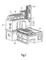
- the Fig. 1 shows a machine tool with a machine table 10, on which a portal 11 is mounted with a crossbar 12.
- a carriage 14 In a working space 13, which is formed by the portal 11, a carriage 14 is movable along a horizontal axis of movement.
- a cross slide 15 is movable along a further horizontal axis relative to the traverse 12.
- the cross slide 15 carries a vertical slide 16, on which a spindle 17 is mounted, which forms a rotatable shaft, at the end of a tool 18 is mounted.
- On the representation of the attachment of a workpiece on the carriage 14 has been made For the sake of simplification omitted.
- the basic structure of the machine tool is known from the prior art, so that it is possible to dispense with further embodiments at this point.
- a sensor 1 is attached to the housing of the spindle 17, by which vibrations of the spindle 17 can be determined.
- the reference numeral 2 designates a sensor (transducer), which is provided on the traverse 12 in order to determine horizontal movements of the cross slide 15 and to control the carriage 15 or to regulate. Occurring vibrations can thus be determined directly by changes in the position signal of the measuring sensor 2, for example directly as vibrations or at least as amplified noise.
- the Fig. 2 shows a graphical representation of the oscillations (amplitude) A as a function of the speed n of the spindle 17.
- the rotational speed n SOLL to which according to the invention first the spindle 17 is brought. The speed is then increased or decreased according to the invention by a predetermined value.
- the limits of increase or decrease are the values n MAX and n MIN, respectively.
- a curve of the oscillation amplitude results over the speed range, a curve of the oscillation amplitude. This has a minimum value at the speed value n OPTIMAL . This is the optimum speed value which is set in the method according to the invention and in which an optimization of the vibration behavior is present.
Claims (11)
- Procédé d'usinage d'une pièce par enlèvement de copeaux au moyen d'une machine-outil et d'optimisation des vibrations de la machine-outil lors de l'usinage, dans le cadre duquel une opération d'usinage est interrompue, dans le cadre duquel un arbre entraîné (17) est mis en rotation à une vitesse de rotation de consigne, aucun autre mouvement n'étant réalisé le long des axes de mouvement de la machine-outil, dans le cadre duquel la vitesse de rotation de consigne est ensuite augmentée et/ou diminuée automatiquement d'au moins une valeur prédéfinie, les vibrations apparaissant étant mesurées dans la plage de vitesse de rotation sélectionnée supérieure et/ou inférieure à la vitesse de rotation de consigne, une vitesse de rotation optimale avec vibration minimisée étant déterminée et réglée, et dans le cadre duquel la pièce est ensuite usinée avec la vitesse de rotation optimale.
- Procédé selon la revendication 1, caractérisé en ce que la plage de vitesse de rotation définie par la vitesse de rotation supérieure et la vitesse de rotation inférieure est balayée de manière continue.
- Procédé selon la revendication 1, caractérisé en ce que la plage de vitesse de rotation définie par la vitesse de rotation supérieure et la vitesse de rotation inférieure est balayée graduellement.
- Procédé selon l'une quelconque des revendications 1 à 3, caractérisé en ce que le procédé est répété dans des intervalles de temps prédéfinis lors de l'interruption de l'usinage.
- Procédé selon l'une quelconque des revendications 1 à 4, caractérisé en ce qu'au moins un capteur (1) supplémentaire est utilisé pour déterminer les vibrations.
- Procédé selon l'une quelconque des revendications 1 à 5, caractérisé en ce qu'au moins un enregistreur de mesure (2) est utilisé pour déterminer les vibrations.
- Procédé selon l'une quelconque des revendications 1 à 6, caractérisé en ce qu'au moins un mouvement d'avance d'un axe de mouvement de la machine-outil est ajusté à la vitesse de rotation optimale modifiée.
- Procédé selon l'une quelconque des revendications 1 à 7, caractérisé en ce que la mesure de la vitesse de rotation se fait sous forme de mesure de l'amplitude de la vibration.
- Procédé selon l'une quelconque des revendications 1 à 8, caractérisé en ce que la mesure de la vitesse de rotation se fait sous forme de mesure de la modification du signal d'un enregistreur de mesure.
- Procédé selon l'une quelconque des revendications 1 à 9, caractérisé en ce que le procédé est répété dans des intervalles de temps prédéfinis.
- Procédé selon l'une quelconque des revendications 1 à 10, caractérisé en ce que le procédé est répété dans le cas d'une modification des paramètres d'usinage d'une pièce.
Applications Claiming Priority (2)
| Application Number | Priority Date | Filing Date | Title |
|---|---|---|---|
| DE102005023317A DE102005023317A1 (de) | 2005-05-20 | 2005-05-20 | Verfahren zur Schwingungsoptimierung einer Werkzeugmaschine |
| PCT/EP2006/003135 WO2006122611A1 (fr) | 2005-05-20 | 2006-04-06 | Procede d'optimisation des vibrations d'une machine-outil |
Publications (2)
| Publication Number | Publication Date |
|---|---|
| EP1890839A1 EP1890839A1 (fr) | 2008-02-27 |
| EP1890839B1 true EP1890839B1 (fr) | 2009-08-05 |
Family
ID=36581741
Family Applications (1)
| Application Number | Title | Priority Date | Filing Date |
|---|---|---|---|
| EP06742543A Active EP1890839B1 (fr) | 2005-05-20 | 2006-04-06 | Procede d'optimisation des vibrations d'une machine-outil |
Country Status (6)
| Country | Link |
|---|---|
| US (1) | US8317440B2 (fr) |
| EP (1) | EP1890839B1 (fr) |
| JP (1) | JP2008540146A (fr) |
| CN (1) | CN101180157B (fr) |
| DE (2) | DE102005023317A1 (fr) |
| WO (1) | WO2006122611A1 (fr) |
Cited By (1)
| Publication number | Priority date | Publication date | Assignee | Title |
|---|---|---|---|---|
| DE102010023190A1 (de) * | 2010-06-09 | 2011-12-15 | Liebherr-Verzahntechnik Gmbh | Verfahren und Werkzeugmaschine zur spanabhebenden Werkstückbearbeitung |
Families Citing this family (20)
| Publication number | Priority date | Publication date | Assignee | Title |
|---|---|---|---|---|
| US20110000348A1 (en) | 2008-03-07 | 2011-01-06 | Pierantonio Melandri | Control and management method for lathes and loaders for lathes and apparatus for performing the method |
| JP5234772B2 (ja) * | 2008-10-28 | 2013-07-10 | オークマ株式会社 | 工作機械の振動抑制方法及び装置 |
| CN102596495A (zh) * | 2009-11-13 | 2012-07-18 | 三菱重工业株式会社 | 作业机械的控制方法及控制装置 |
| US20110126813A1 (en) * | 2009-12-01 | 2011-06-02 | Diamond Wire Technology, Inc. | Multi-wire wafer cutting apparatus and method |
| US8985068B2 (en) | 2010-07-22 | 2015-03-24 | Robert Bosch Gmbh | Systems and methods for avoiding resonances excited by rotating components |
| US8700201B2 (en) * | 2010-09-13 | 2014-04-15 | Okuma Corporation | Vibration suppressing device |
| JP5536611B2 (ja) * | 2010-10-15 | 2014-07-02 | オークマ株式会社 | 工作機械のモニタ方法及びモニタ装置、工作機械 |
| JP5643676B2 (ja) * | 2011-02-24 | 2014-12-17 | オークマ株式会社 | 振動抑制機能を備えた数値制御装置 |
| JP5258921B2 (ja) | 2011-03-31 | 2013-08-07 | 株式会社小松製作所 | 工作機械及びその加工制御装置 |
| CN102416580A (zh) * | 2011-12-07 | 2012-04-18 | 常州市新特力工具有限公司 | 镗床的控制装置 |
| JP5964159B2 (ja) * | 2012-07-05 | 2016-08-03 | 東芝機械株式会社 | 精密工作機械 |
| DE102013209457B4 (de) | 2013-05-22 | 2024-02-01 | Gühring KG | Verfahren zum Gestalten eines Bohrwerkzeugs, Bohrwerkzeug sowie Verfahren zum Bearbeiten von Werkstücken aus Verbundmaterial mit Hilfe eines Bohrwerkzeugs |
| US10295475B2 (en) | 2014-09-05 | 2019-05-21 | Rolls-Royce Corporation | Inspection of machined holes |
| TWM507316U (zh) * | 2015-05-21 | 2015-08-21 | Jinn Fa Machine Ind Co Ltd | 工具機之承載裝置 |
| US10228669B2 (en) | 2015-05-27 | 2019-03-12 | Rolls-Royce Corporation | Machine tool monitoring |
| JP6538430B2 (ja) | 2015-05-29 | 2019-07-03 | オークマ株式会社 | 工作機械の振動情報表示装置 |
| DE102016224749A1 (de) * | 2016-12-12 | 2018-06-14 | Robert Bosch Gmbh | Werkzeugmaschine zur spanenden Bearbeitung eines Werkstücks |
| DE102017101581A1 (de) * | 2017-01-26 | 2018-07-26 | Homag Plattenaufteiltechnik Gmbh | Verfahren zum Betreiben einer Werkstückbearbeitungsanlage, sowie Werkstückbearbeitungsanlage |
| JP2018161724A (ja) * | 2017-03-27 | 2018-10-18 | ファナック株式会社 | 工作機械システムおよびクランプ方法 |
| DE102019110137A1 (de) * | 2019-04-17 | 2020-10-22 | Homag Gmbh | Bearbeitungsverfahren |
Family Cites Families (35)
| Publication number | Priority date | Publication date | Assignee | Title |
|---|---|---|---|---|
| US3504581A (en) | 1967-04-24 | 1970-04-07 | Gen Electric | Apparatus for early detection of tool chatter in machining operations |
| US3473435A (en) * | 1967-04-26 | 1969-10-21 | Jason R Lemon | Vibration controller for machine tools |
| CH486289A (de) * | 1968-08-08 | 1970-02-28 | Kistler Instrumente Ag | Elektrische Überwachungsanlage für Werkzeugmaschinen |
| DE2042138C3 (de) * | 1970-08-25 | 1974-02-14 | Gebrueder Boehringer Gmbh, 7320 Goeppingen | Verfahren zum Verhindern regenerativen Ratterns bei der spanabhebenden Bearbeitung eines Werkstücks und Einrichtung zum Durchführen des Verfahrens |
| US3967515A (en) * | 1974-05-13 | 1976-07-06 | Purdue Research Foundation | Apparatus for controlling vibrational chatter in a machine-tool utilizing an updated synthesis circuit |
| US3872285A (en) * | 1974-05-31 | 1975-03-18 | Westinghouse Electric Corp | Control system for sensing the vibration and lateral force on a cutting tool |
| JPS5153686A (en) * | 1974-11-05 | 1976-05-12 | Kogyo Gijutsuin | Kosakukikainiokeru bibirishindoyokuseihoho |
| DE2520946A1 (de) * | 1975-05-10 | 1976-11-18 | Scharmann & Co | Verfahren zur verhinderung oder beseitigung von ratterschwingungen der arbeitsspindel von werkzeugmaschinen und einrichtung zur durchfuehrung dieses verfahrens |
| DD137547A1 (de) * | 1978-07-26 | 1979-09-12 | Horst Weber | Anordnung zur umgehung standzeitunguenstiger bearbeitungsparameter |
| US4428055A (en) * | 1981-08-18 | 1984-01-24 | General Electric Company | Tool touch probe system and method of precision machining |
| US4604834A (en) * | 1985-10-03 | 1986-08-12 | General Electric Company | Method and apparatus for optimizing grinding |
| FR2600001B1 (fr) * | 1986-06-11 | 1988-09-09 | Meseltron Sa | Dispositif pour la commande de la vitesse d'avance d'un outil vers une piece a usiner |
| US4759243A (en) * | 1986-12-19 | 1988-07-26 | General Electric Company | Method and apparatus for optimizing single point machining operations |
| US4967154A (en) * | 1989-09-13 | 1990-10-30 | Optima Industries, Inc. | Dynamic tube runout measuring method and apparatus with square wave energized reluctance measuring coils |
| JPH0755429B2 (ja) * | 1989-10-03 | 1995-06-14 | 三菱電機株式会社 | 工作機械の主軸駆動装置 |
| US5170358A (en) * | 1990-12-06 | 1992-12-08 | Manufacturing Laboratories, Inc. | Method of controlling chatter in a machine tool |
| JPH07186002A (ja) * | 1993-12-27 | 1995-07-25 | Seiko Seiki Co Ltd | スピンドル装置 |
| JPH08229772A (ja) * | 1995-03-01 | 1996-09-10 | Toyota Motor Corp | 主軸回転数の設定方法および装置 |
| US5518347A (en) * | 1995-05-23 | 1996-05-21 | Design And Manufacturing Solutions, Inc. | Tuned damping system for suppressing vibrations during machining |
| US6004017A (en) * | 1996-11-07 | 1999-12-21 | Madhavan; Poovanpilli G. | Teager-based method and system for predicting limit cycle oscillations and control method and system utilizing same |
| US5784273A (en) * | 1996-11-07 | 1998-07-21 | Madhavan; Poovanpilli G. | Method and system for predicting limit cycle oscillations and control method and system utilizing same |
| US6085121A (en) * | 1997-09-22 | 2000-07-04 | Design & Manufacturing Solutions, Inc. | Device and method for recommending dynamically preferred speeds for machining |
| JPH11300578A (ja) * | 1998-04-21 | 1999-11-02 | Toshiba Mach Co Ltd | 工作機械の数値制御装置 |
| US6367359B1 (en) * | 1998-11-18 | 2002-04-09 | Ronald P. Ropos | Boring and contouring apparatus |
| US6349600B1 (en) * | 1999-03-15 | 2002-02-26 | The Government Of The United States Of America, As Represented By The Secretary Of Commerce | Device for stable speed determination in machining |
| US20020146296A1 (en) * | 2001-02-26 | 2002-10-10 | National Institute Of Standards And Technology | Method and device for avoiding chatter during machine tool operation |
| CN1128040C (zh) * | 2001-12-19 | 2003-11-19 | 北京工业大学 | 机床切削颤振在线智能控制方法 |
| DE10244426B4 (de) * | 2002-09-24 | 2005-02-10 | Siemens Ag | Bearbeitungsmaschine |
| US20050021265A1 (en) * | 2003-03-25 | 2005-01-27 | Esterling Donald M. | Method for reducing the measurement requirements for the dynamic response of tools in a CNC machine |
| US6993410B2 (en) * | 2003-03-25 | 2006-01-31 | Donald M. Esterling | Active electromagnetic device for measuring the dynamic response of a tool in a CNC machine |
| US6810302B2 (en) * | 2003-03-31 | 2004-10-26 | Sikorsky Aircraft Corporation | Process and methodology for selecting cutting parameters for titanium |
| TWI289092B (en) * | 2005-01-18 | 2007-11-01 | Univ Chung Yuan Christian | Detecting and suppressing methods for milling tool chatter |
| TWI268196B (en) * | 2005-02-23 | 2006-12-11 | Univ Chung Yuan Christian | Computer aided detecting and suppressing system for cutting chatter comprising a network monitor unit, a signal acquisition system, a chatter detecting unit and a chatter suppressing system |
| US8011864B2 (en) * | 2005-05-26 | 2011-09-06 | University Of Connecticut | Method for facilitating chatter stability mapping in a simultaneous machining application |
| JP2008229772A (ja) | 2007-03-20 | 2008-10-02 | Naomasa Nitta | ハンマー |
-
2005
- 2005-05-20 DE DE102005023317A patent/DE102005023317A1/de not_active Withdrawn
-
2006
- 2006-04-06 DE DE502006004454T patent/DE502006004454D1/de active Active
- 2006-04-06 JP JP2008511572A patent/JP2008540146A/ja active Pending
- 2006-04-06 WO PCT/EP2006/003135 patent/WO2006122611A1/fr active Application Filing
- 2006-04-06 CN CN200680017538.7A patent/CN101180157B/zh not_active Expired - Fee Related
- 2006-04-06 EP EP06742543A patent/EP1890839B1/fr active Active
- 2006-04-06 US US11/914,004 patent/US8317440B2/en active Active
Cited By (1)
| Publication number | Priority date | Publication date | Assignee | Title |
|---|---|---|---|---|
| DE102010023190A1 (de) * | 2010-06-09 | 2011-12-15 | Liebherr-Verzahntechnik Gmbh | Verfahren und Werkzeugmaschine zur spanabhebenden Werkstückbearbeitung |
Also Published As
| Publication number | Publication date |
|---|---|
| WO2006122611A1 (fr) | 2006-11-23 |
| US8317440B2 (en) | 2012-11-27 |
| DE102005023317A1 (de) | 2006-11-23 |
| US20090013790A1 (en) | 2009-01-15 |
| EP1890839A1 (fr) | 2008-02-27 |
| JP2008540146A (ja) | 2008-11-20 |
| CN101180157A (zh) | 2008-05-14 |
| CN101180157B (zh) | 2011-03-30 |
| DE502006004454D1 (de) | 2009-09-17 |
Similar Documents
| Publication | Publication Date | Title |
|---|---|---|
| EP1890839B1 (fr) | Procede d'optimisation des vibrations d'une machine-outil | |
| DE102006049867B4 (de) | Werkzeugmaschine und Verfahren zur Unterdrückung von Ratterschwingungen | |
| EP1954442B1 (fr) | Procede de reduction des vibrations d'un element de machine et / ou d'une piece | |
| DE102005056603B4 (de) | Verfahren zur Reduktion von während eines Bearbeitungsvorgangs auftretenden Schwingungen eines Maschinenelementes und/oder eines Werkstücks | |
| DE102007025934B4 (de) | Werkzeugmaschine | |
| EP3153277B1 (fr) | Tete d'usinage dotee d'un dispositif d'equilibrage | |
| EP3363573B1 (fr) | Dispositif et procédé d'usinage de pièces d'usinage sur une machine à tailler | |
| DE4405660A1 (de) | Verfahren und Anordnung zum Betreiben einer spanabhebenden Werkzeugmaschine, insbesondere Kreissäge-, Fräs-, Schleifmaschine oder dergleichen | |
| DE102009020246A1 (de) | Verfahren und Mehrachsen-Bearbeitungsmaschine zur zerspanenden Bearbeitung | |
| EP3574379B1 (fr) | Procédé de fonctionnement d'une installation de traitement de pièces à usiner, et installation de traitement de pièces à usiner | |
| DE102008022993A1 (de) | Fräsverfahren zur Verbesserung der Oberflächengüte und Minimierung des Werkzeugverschleißes sowie Vorrichtung hierzu | |
| EP3551375A1 (fr) | Machine-outil pour l'usinage d'une pièce par enlèvement de copeaux | |
| EP0883463B1 (fr) | Procede et dispositif de compensation de decalages dynamiques sur des machines-outils d'usinage | |
| EP1707310B1 (fr) | Procédé d'extension de la largeur de bande d'un système d'entraînement comprenant un moteur et un système mécanique oscillant couplé, de préférence sur la base de systèmes à vis à billes, ainsi que commande d'avance pour la mise en oeuvre d'un tel procédé | |
| EP2676174A2 (fr) | Procédé et dispositif de régulation de l'entraînement pour un outil ou une pièce | |
| DE19630694A1 (de) | Verfahren und Vorrichtung zur Kompensation dynamischer Verlagerungen an spanabhebenden Werkzeugmaschinen | |
| EP2124116B1 (fr) | Procédé de commande d'un appareil de mesure des coordonnées à commande numérique assistée par ordinateur et appareil de mesure de coordonnées | |
| EP2883635B1 (fr) | Dispositif d'équilibrage et méthode d'équilibrage pour un magasin de stockage de tiges | |
| WO2006072404A1 (fr) | Dispositif a broches et procede pour influencer les oscillations et les deviations desdites broches | |
| DE102020122685A1 (de) | Parametereinstellverfahren und steuervorrichtung | |
| DE10142739B4 (de) | Maschine zum Hinterarbeiten eines um eine Drehachse rotierenden Werkstücks | |
| AT525081B1 (de) | Verfahren und vorrichtung zur steuerung der vorschubgeschwindigkeit von sägeblättern | |
| EP3840914B1 (fr) | Dispositif d'ajustement pour une machine-outil présentant une tendance à l'oscillation réduite | |
| EP2415556A1 (fr) | Entraînement pour une machine dotée d'un réglage de point de travail couplé à des impulsions | |
| DE112022000256T5 (de) | Steuervorrichtung und Rechenvorrichtung |
Legal Events
| Date | Code | Title | Description |
|---|---|---|---|
| PUAI | Public reference made under article 153(3) epc to a published international application that has entered the european phase |
Free format text: ORIGINAL CODE: 0009012 |
|
| 17P | Request for examination filed |
Effective date: 20071113 |
|
| AK | Designated contracting states |
Kind code of ref document: A1 Designated state(s): CH DE IT LI |
|
| 17Q | First examination report despatched |
Effective date: 20080505 |
|
| RBV | Designated contracting states (corrected) |
Designated state(s): CH DE IT LI |
|
| DAX | Request for extension of the european patent (deleted) | ||
| GRAP | Despatch of communication of intention to grant a patent |
Free format text: ORIGINAL CODE: EPIDOSNIGR1 |
|
| GRAS | Grant fee paid |
Free format text: ORIGINAL CODE: EPIDOSNIGR3 |
|
| GRAA | (expected) grant |
Free format text: ORIGINAL CODE: 0009210 |
|
| AK | Designated contracting states |
Kind code of ref document: B1 Designated state(s): CH DE IT LI |
|
| REG | Reference to a national code |
Ref country code: CH Ref legal event code: EP |
|
| REG | Reference to a national code |
Ref country code: CH Ref legal event code: NV Representative=s name: KELLER & PARTNER PATENTANWAELTE AG |
|
| REF | Corresponds to: |
Ref document number: 502006004454 Country of ref document: DE Date of ref document: 20090917 Kind code of ref document: P |
|
| PLBE | No opposition filed within time limit |
Free format text: ORIGINAL CODE: 0009261 |
|
| STAA | Information on the status of an ep patent application or granted ep patent |
Free format text: STATUS: NO OPPOSITION FILED WITHIN TIME LIMIT |
|
| 26N | No opposition filed |
Effective date: 20100507 |
|
| PGFP | Annual fee paid to national office [announced via postgrant information from national office to epo] |
Ref country code: IT Payment date: 20100427 Year of fee payment: 5 |
|
| PG25 | Lapsed in a contracting state [announced via postgrant information from national office to epo] |
Ref country code: IT Free format text: LAPSE BECAUSE OF NON-PAYMENT OF DUE FEES Effective date: 20110406 |
|
| REG | Reference to a national code |
Ref country code: DE Ref legal event code: R082 Ref document number: 502006004454 Country of ref document: DE Representative=s name: HOEFER & PARTNER, DE |
|
| REG | Reference to a national code |
Ref country code: DE Ref legal event code: R082 Ref document number: 502006004454 Country of ref document: DE Representative=s name: HOEFER & PARTNER, DE Effective date: 20120807 Ref country code: DE Ref legal event code: R081 Ref document number: 502006004454 Country of ref document: DE Owner name: P&L GMBH & CO. KG, DE Free format text: FORMER OWNER: P & L GMBH & CO. KG, 20148 HAMBURG, DE Effective date: 20120807 Ref country code: DE Ref legal event code: R081 Ref document number: 502006004454 Country of ref document: DE Owner name: P & L GMBH & CO. KG, DE Free format text: FORMER OWNER: P & L GMBH & CO. KG, 20148 HAMBURG, DE Effective date: 20120807 Ref country code: DE Ref legal event code: R082 Ref document number: 502006004454 Country of ref document: DE Representative=s name: HOEFER & PARTNER PATENTANWAELTE MBB, DE Effective date: 20120807 |
|
| REG | Reference to a national code |
Ref country code: CH Ref legal event code: PCAR Free format text: NEW ADDRESS: EIGERSTRASSE 2 POSTFACH, 3000 BERN 14 (CH) |
|
| PGFP | Annual fee paid to national office [announced via postgrant information from national office to epo] |
Ref country code: CH Payment date: 20150422 Year of fee payment: 10 |
|
| REG | Reference to a national code |
Ref country code: CH Ref legal event code: PL |
|
| PG25 | Lapsed in a contracting state [announced via postgrant information from national office to epo] |
Ref country code: CH Free format text: LAPSE BECAUSE OF NON-PAYMENT OF DUE FEES Effective date: 20160430 Ref country code: LI Free format text: LAPSE BECAUSE OF NON-PAYMENT OF DUE FEES Effective date: 20160430 |
|
| PGFP | Annual fee paid to national office [announced via postgrant information from national office to epo] |
Ref country code: DE Payment date: 20230427 Year of fee payment: 18 |