EP1882983A1 - Support de compensation de la gravité pour élément optique - Google Patents
Support de compensation de la gravité pour élément optique Download PDFInfo
- Publication number
- EP1882983A1 EP1882983A1 EP06117813A EP06117813A EP1882983A1 EP 1882983 A1 EP1882983 A1 EP 1882983A1 EP 06117813 A EP06117813 A EP 06117813A EP 06117813 A EP06117813 A EP 06117813A EP 1882983 A1 EP1882983 A1 EP 1882983A1
- Authority
- EP
- European Patent Office
- Prior art keywords
- optical element
- gravity
- gravity compensation
- negative pressure
- force
- Prior art date
- Legal status (The legal status is an assumption and is not a legal conclusion. Google has not performed a legal analysis and makes no representation as to the accuracy of the status listed.)
- Withdrawn
Links
Images


Classifications
-
- G—PHYSICS
- G03—PHOTOGRAPHY; CINEMATOGRAPHY; ANALOGOUS TECHNIQUES USING WAVES OTHER THAN OPTICAL WAVES; ELECTROGRAPHY; HOLOGRAPHY
- G03F—PHOTOMECHANICAL PRODUCTION OF TEXTURED OR PATTERNED SURFACES, e.g. FOR PRINTING, FOR PROCESSING OF SEMICONDUCTOR DEVICES; MATERIALS THEREFOR; ORIGINALS THEREFOR; APPARATUS SPECIALLY ADAPTED THEREFOR
- G03F7/00—Photomechanical, e.g. photolithographic, production of textured or patterned surfaces, e.g. printing surfaces; Materials therefor, e.g. comprising photoresists; Apparatus specially adapted therefor
- G03F7/70—Microphotolithographic exposure; Apparatus therefor
- G03F7/708—Construction of apparatus, e.g. environment aspects, hygiene aspects or materials
- G03F7/70908—Hygiene, e.g. preventing apparatus pollution, mitigating effect of pollution or removing pollutants from apparatus
- G03F7/70916—Pollution mitigation, i.e. mitigating effect of contamination or debris, e.g. foil traps
-
- G—PHYSICS
- G02—OPTICS
- G02B—OPTICAL ELEMENTS, SYSTEMS OR APPARATUS
- G02B7/00—Mountings, adjusting means, or light-tight connections, for optical elements
- G02B7/02—Mountings, adjusting means, or light-tight connections, for optical elements for lenses
- G02B7/023—Mountings, adjusting means, or light-tight connections, for optical elements for lenses permitting adjustment
-
- G—PHYSICS
- G03—PHOTOGRAPHY; CINEMATOGRAPHY; ANALOGOUS TECHNIQUES USING WAVES OTHER THAN OPTICAL WAVES; ELECTROGRAPHY; HOLOGRAPHY
- G03F—PHOTOMECHANICAL PRODUCTION OF TEXTURED OR PATTERNED SURFACES, e.g. FOR PRINTING, FOR PROCESSING OF SEMICONDUCTOR DEVICES; MATERIALS THEREFOR; ORIGINALS THEREFOR; APPARATUS SPECIALLY ADAPTED THEREFOR
- G03F7/00—Photomechanical, e.g. photolithographic, production of textured or patterned surfaces, e.g. printing surfaces; Materials therefor, e.g. comprising photoresists; Apparatus specially adapted therefor
- G03F7/70—Microphotolithographic exposure; Apparatus therefor
- G03F7/70058—Mask illumination systems
- G03F7/70141—Illumination system adjustment, e.g. adjustments during exposure or alignment during assembly of illumination system
-
- G—PHYSICS
- G03—PHOTOGRAPHY; CINEMATOGRAPHY; ANALOGOUS TECHNIQUES USING WAVES OTHER THAN OPTICAL WAVES; ELECTROGRAPHY; HOLOGRAPHY
- G03F—PHOTOMECHANICAL PRODUCTION OF TEXTURED OR PATTERNED SURFACES, e.g. FOR PRINTING, FOR PROCESSING OF SEMICONDUCTOR DEVICES; MATERIALS THEREFOR; ORIGINALS THEREFOR; APPARATUS SPECIALLY ADAPTED THEREFOR
- G03F7/00—Photomechanical, e.g. photolithographic, production of textured or patterned surfaces, e.g. printing surfaces; Materials therefor, e.g. comprising photoresists; Apparatus specially adapted therefor
- G03F7/70—Microphotolithographic exposure; Apparatus therefor
- G03F7/70216—Mask projection systems
- G03F7/70258—Projection system adjustments, e.g. adjustments during exposure or alignment during assembly of projection system
- G03F7/70266—Adaptive optics, e.g. deformable optical elements for wavefront control, e.g. for aberration adjustment or correction
-
- G—PHYSICS
- G03—PHOTOGRAPHY; CINEMATOGRAPHY; ANALOGOUS TECHNIQUES USING WAVES OTHER THAN OPTICAL WAVES; ELECTROGRAPHY; HOLOGRAPHY
- G03F—PHOTOMECHANICAL PRODUCTION OF TEXTURED OR PATTERNED SURFACES, e.g. FOR PRINTING, FOR PROCESSING OF SEMICONDUCTOR DEVICES; MATERIALS THEREFOR; ORIGINALS THEREFOR; APPARATUS SPECIALLY ADAPTED THEREFOR
- G03F7/00—Photomechanical, e.g. photolithographic, production of textured or patterned surfaces, e.g. printing surfaces; Materials therefor, e.g. comprising photoresists; Apparatus specially adapted therefor
- G03F7/70—Microphotolithographic exposure; Apparatus therefor
- G03F7/708—Construction of apparatus, e.g. environment aspects, hygiene aspects or materials
- G03F7/70808—Construction details, e.g. housing, load-lock, seals or windows for passing light in or out of apparatus
- G03F7/70825—Mounting of individual elements, e.g. mounts, holders or supports
Definitions
- the invention relates to a support structure for an optical element and an optical element module comprising such a support structure. Furthermore, it relates to a method of supporting an optical element.
- the invention may be used in the context of photolithography processes for fabricating microelectronic devices, in particular semiconductor devices, or in the context of fabricating devices, such as masks or reticles, used during such photolithography processes.
- optical elements participating in the exposure process to account for manufacturing tolerances as well as drifts and degradations of the system during operation.
- these optical elements have to be actively positioned in more than one degree of freedom (DOF).
- DOE degree of freedom
- contactless actuators such as so-called voice coil actuators or Lorentz actuators
- voice coil actuators or Lorentz actuators are used to avoid such parasitic forces.
- these contactless actuators typically have the disadvantage that they have to be continuously energized in order to bear the static load resulting from the gravitational force acting on the optical element to be held.
- considerable heat is generated at these contactless actuators which in turn may lead to thermally induced deformations that deteriorate imaging accuracy.
- coil springs multiple coil springs with evenly distributed coils may be used, for example, since they have the advantage of a rather low stiffness and - thanks to the even circumferential distribution of the coils - they do not produce parasitic moments.
- permanent magnetic springs magnetic devices may be used as they are known e.g. from US 2004/0212794 A1 (Mizuno ), US 2003/0052284 A1 (Hol et al. ) and US 2005/0002008 A1 (De Weerdt et al. ), the entire disclosure of all of which is incorporated herein by reference.
- All these spring elements have a certain stiffness leading to a change in the spring force provided by the spring element upon an excursion of the optical element from a neutral position.
- This change in the spring force causes the problem that the contactless actuator, in addition to providing the force necessary for accelerating the optical element, has to negotiate the difference between the spring force and the gravitational force acting on the optical element leading to and increased energy consumption of the contactless actuator with the associated heat generation.
- the known passive spring elements may provide good results for a rather small positioning range of the optical element they have the disadvantage that they are unsuitable for applications with a larger positioning range , e.g. starting from 10 mm and more.
- the force of the gravity compensation device may be easily kept substantially constant by a simple pressure control. This, in principle, would allow a virtually unlimited positioning range.
- this pneumatic gravity compensation solution as the disadvantage that there is a considerable inertia in the system due to the relatively large mass of gas that has to be supplied to the positive pressure chamber leading to an increase in the reaction time of the system. Furthermore, the relatively large amount of gas to be conveyed leads to considerable internal friction within the gas.
- a further disadvantage of such a known pneumatic gravity compensation system is the fact that the pressurized gas escapes through the gap between the piston and the cylinder and eventually contaminates the atmosphere surrounding the optical element.
- costly measures such as evacuation lines close to the piston as proposed in the above US 2004/0001188 A1 (Janssen et al. ), have to be taken to account for this problem.
- a highly dynamic gravity compensation allowing increased positioning ranges without deteriorating the imaging accuracy may be achieved by using a negative pressure for generating a force that counteracts the gravitational force acting on the optical element to be supported.
- the use of the pressure of based gravity compensation due to the simple pressure control that may be achieved, the gravity compensation force may be easily kept at least close to its optimum value over a virtually unlimited positioning range of the optical element. Since virtually no energy has to be supplied to the system in proximity of the optical element the problem of heat generation and introduction into the optical system under static load conditions is largely avoided.
- the use of a negative pressure has the advantage that a lower mass of working medium is to be conveyed when positioning the optical element.
- a lower inertia and lower internal friction is to be dealt with leading to improved dynamic properties of the system.
- the use of the negative pressure simply eliminates the contamination problem since there is no material transport through any sealing gap of the gravity compensation device used towards the surroundings of the optical element.
- the gravity compensation may be achieved in a simple and space saving manner by implementing a simple cylinder and piston arrangement forming a negative pressure chamber wherein the negative pressure is provided by a suitable negative pressure source.
- the control keeping the gravity compensation force substantially equal to the gravitational force acting on the optical element during the positioning process may be a simple pressure control. It may be provided, for example, via a pressure sensor providing the actual level of negative pressure to a suitable control device adjusting the negative pressure to a given setpoint value.
- positioning ranges - i.e. a travel of the optical element from one extreme position to its other extreme position - of more than 10 mm to 30 mm, even more than 50 mm may be achieved at substantially optimized gravity compensation force. This may be done within a very short interval of less than two seconds, even less than one second.
- an optical element module comprising an optical element and a support structure supporting the optical element.
- the support structure comprises an actuator device and a gravity compensation device.
- the actuator device is mechanically connected to the optical element and adapted to exert an actuation force on the optical element, the actuation force accelerating the optical element.
- the gravity compensation device comprises a gravity compensator.
- the gravity compensator is mechanically connected to the optical element and adapted to exert a gravity compensation force on the optical element when a negative pressure is acting within the gravity compensator.
- the gravity compensation force counteracts at least a part of the gravitational force acting on the optical element. It will be appreciated here that more than one gravity compensator may be used to fully compensate the gravitational force acting on the optical element.
- an optical exposure apparatus for transferring an image of a pattern formed on a mask onto a substrate comprising an illumination system adapted to provide light of a light path, a mask unit located within the light path and adapted to receive the mask, a substrate unit located at an end of the light path and adapted to receive the substrate, an optical projection system located within the light path between the mask location and the substrate location and adapted to transfer an image of the pattern onto the substrate.
- At least one of the illumination system and the optical projection system comprises an optical element module according do the first aspect of the invention.
- a support structure for supporting an optical element comprising an actuator device and a gravity compensation device.
- the actuator device is adapted to be mechanically connected to the optical element and to exert an actuation force on the optical element, the actuation force accelerating the optical element.
- the gravity compensation device comprises a gravity compensator, the gravity compensator being adapted to be mechanically connected to the optical element and to exert a gravity compensation force on the optical element when a negative pressure is acting within the gravity compensator.
- the gravity compensation force counteracts at least a part of the gravitational force acting on the optical element.
- a method of supporting an optical element comprising providing an optical element and a gravity compensation device, exerting a gravity compensation force on the optical element via the gravity compensation device, the gravity compensation force counteracting at least a part of the gravitational force acting on the optical element.
- the exerting the gravity compensation force comprises generating the gravity compensation force using a negative pressure.
- more than one gravity compensator and gravity compensation force may be used to fully compensate the gravitational force acting on the optical element.
- the full gravity compensation of the optical element is provided by one single gravity compensator and gravity compensation force, respectively.
- the above aspects of the invention are used in the context of microlithography applications.
- the invention may also be used in any other type of optical exposure process or any other type of supporting an element being either an optical or not.
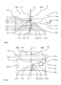
- an optical exposure apparatus 101 comprising an illumination system 102, a mask unit 103 holding a mask 104, an optical projection system 105 and a substrate unit 106 holding a substrate 107 will be described with reference to Figures 1 and 2.
- the optical exposure apparatus is a microlithography apparatus 101 that is adapted to transfer an image of a pattern formed on the mask 104 onto the substrate 107.
- the illumination system 102 illuminates the mask 104 with exposure light.
- the optical projection system 105 projects the image of the pattern formed on the mask 104 onto the substrate 107, e.g. a wafer or the like.
- the illumination system 102 comprises a light source 102.1 and a first optical element group 108 with a plurality of optical elements cooperating to define the beam of exposure light-schematically indicated by the double-dot-dashed contour 109 in Figure 1 - by which the mask 104 is illuminated.
- the optical projection system 104 comprises a second optical element group 110 with a plurality of optical elements cooperating to transfer an image of the pattern formed on the mask 104 onto the substrate 107.
- the light source 102.1 provides light at a wavelength of 193 nm.
- the optical elements of the first optical element group 108 and the second optical element group 110 are refractive optical elements, i.e. lenses or the like.
- any types of optical elements e.g. lenses, mirrors, gratings etc may be used alone or in an arbitrary combination.
- the wafer 107 is temporarily supported on a wafer table 106.1 forming part of the substrate unit 106.
- the wafer 107 is moved at certain points in time relative to the optical projection system 105 to form a plurality of dies on the wafer 107.
- the wafer 107 is removed from the exposure area and the next wafer is placed in the exposure area.
- the illumination setting of the illumination system 102 has to be rapidly changed.
- the position of an optical element in the form of the lens 108.1 of the first optical element group 108 has to be rapidly changed in order to achieve a high throughput of the microlithography apparatus 101.
- the lens 108.1 - shown in a highly schematic manner- forms part of an optical element module 111.
- the optical element module 111 comprises a support structure 112 supporting the lens 108.1.
- the support structure 112 in turn, comprises a base structure 112.1, an actuator device 113 and a gravity compensation device 114.
- the actuator device 113 comprises three actuator pairs 113.1 (only one of them being shown in Figure 1 for reasons of clarity).
- the actuator pairs 113.1 are evenly distributed at the circumference of the lens 108.1.
- Each actuator pair 113.1 comprises two contactless actuators 113.2, such as voice coil motors (Lorentz actuators) or the like, each mechanically connected to the base structure 112.1 and the lens 108.1.
- the actuator device 113 serves to accelerate and, thus, to position the lens 108.1. To this end, it exerts a corresponding actuation force on the lens 108.1 as will be explained in greater detail below.
- the gravity compensation device 114 comprises three gravity compensators 114.1 each of them being associated to one of the actuator pairs 113.1. Thus, the gravity compensators 114.1 as well are evenly distributed at the circumference of the lens 108.1. Each gravity compensator 114.1 is mechanically connected to the base structure 112.1 and the lens 108.1.
- the gravity compensation device 114 exerts a total gravity compensation force F GCt which counteracts and fully compensates the gravitational force F G acting in the center of gravity (COG) 108.2 of the lens 108.1.
- F GCt the gravitational force
- F G acting in the center of gravity
- the individual gravity compensation forces F GCi exerted by the respective gravity compensator on the lens 108.1 are chosen such that, together, they fully compensate and balance the static forces and moments acting on the lens 108.1. It will be appreciated that, depending on the design of the actuators 113.2, eventually, this may also include forces and/or moments resulting from the weight of certain components of the actuator device 113 mechanically connected to the lens 108.1.
- each gravity compensator 114.1 comprises a cylinder 114.2 and a piston 114.3 slidably mounted within the cylinder 114.2.
- a piston rod 114.4 guided in a suitable bush of the cylinder 114.2 mechanically connects the piston 114.3 to the lens 108.1.
- the cylinder 114.2 and the piston 114.3 define a negative pressure chamber 114.5.
- a negative pressure source 114.6 provides a suitable negative pressure NP within the negative pressure chamber 114.5.
- This negative pressure provided by the negative pressure source 114.6 corresponds to a negative pressure setpoint value NP s which is selected such that, under static load conditions, the above equations (1) and (2) or are fulfilled, i.e. the required individual gravity compensation force F GCi as outlined above is exerted via the piston rod 114.4 on the lens 108.1.
- the negative pressure source 114.6 comprises a simple pressure control which controls the negative pressure NP using the negative pressure setpoint value NP s .
- the pressure control tries to maintain the negative pressure NP within the negative pressure chamber 114.5 as close as possible to the negative pressure setpoint value NP s at any time.
- the pressure control may be fully integrated within the negative pressure source. However, it is also possible, for example, that a suitable pressure sensor of the pressure control is provided within or close to the cylinder 114.2 in order to reduce the reaction time of the control.
- the actuator device 113 is preferably arranged to position the lens 108.1 in more than one degree of freedom (DOF), preferably in up to all six degrees of freedom (DOF).
- DOF degree of freedom
- the location and/or orientation of the lens 108.1 may change such that the negative pressure setpoint value NP s has to be adjusted accordingly in order to achieve fulfilment of the above equations (1) and (2) under static load conditions for this location and/or orientation of the lens 108.1.
- a corresponding control of the negative pressure setpoint value NP s may be superimposed to the negative pressure control as outlined above.
- control of the negative pressure setpoint value NP s may be performed as a function of an operational parameter of the actuator device 113 preferably being representative of the power taken up by the actuator device 113. This may be done in order to reduce the power consumed and, thus, the heat generated by the actuator device 113. For example, it is possible to adjust the negative pressure setpoint value NP s as a function of the electrical current taken by the actuator device 113.
- the control of the negative pressure setpoint value NP s and, thus, of the negative pressure within the negative pressure chamber 114.5 is preferably provided at a low bandwidth, preferably at less than 5 Hz, such that the control does substantially not interfere with the dynamic position control of the lens 108.1 provided via the actuator device 113.
- the current taken and, consequently, the power consumed by the actuator device 113 may be reduced, both, under static load conditions as well as even under dynamic load conditions. This leads to an overall reduction of the heat generated within the actuator device 113 and, thus, within the optical system reducing thermally induced problems such as thermally induced degradation of imaging quality.
- the negative pressure NP is provided to be negative in relation to the pressure prevailing in the atmosphere 115 outside the negative pressure chamber 114.5 and surrounding the lens 108.1.
- the use of the negative pressure NP simply eliminates the contamination problem since there is no material transport through any sealing gap, such as the gap 114.7 formed between the cylinder 114.2 and the piston 114.3 and the gap 114.8 formed between the cylinder 114.2 and the piston rod 114.4, towards the evacuated atmosphere 115 surrounding the lens 108.1. On the contrary, if any, there is only material transport from the atmosphere 115 towards the negative pressure chamber 114.5.
- the negative pressure within the negative pressure chamber may also be only negative in relation to an atmosphere prevailing within a further pressure chamber within the cylinder and lying on the opposite side of the piston. This further pressure chamber is then also sealed from the atmosphere surrounding the lens.
- the lens 108.1 may be positioned over a range of more than 50 mm within less than 1 s. Furthermore, accelerations up to 100 m/s 2 may be achieved with lenses (or other optical elements) weighing 5 kg and more.
- the gravity compensator 114.1 and the actuators 113.2 of the associated actuator pair 113.1 contact the lens 108.1 in a single interface 116 in such a manner that the gravity compensation force line of the individual gravity compensation force F GCi and the actuation force line of the respective actuation force F A intersect at the interface 116.
- an advantageous three-point support is provided to the lens 108.1.
- an end stop device 117 is associated to the respective gravity compensator 114.1.
- the end stop device 117 is formed by a tube 117.1 the upper end of which faces the piston 114.3 while its lower end is mechanically connected to the base of structure 112.1 via two membrane elements 117.2.
- the piston 114.3 will move towards the upper end of the tube 117.1 due to the weight of the lens 108.1.
- the membrane elements 117.2 gradually build up forces acting in the vertical direction in order to slow down and stop the movement of the lens 108.1.
- the tube 117.1 and the membrane elements may also build up such forces in a horizontal plane such that movement of the lens having a horizontal component may also be slowed down and stopped.
- the end stop device 117 may damp the forces acting on the lens 108.1 in case of a failure of its support and avoid damage to the lens 108.1 in this case.
- the end stop device may be of any other suitable design in order to fulfill this task.
- any other resilient and/or damping support may be selected for the part engaging the piston 114.3.
- the piston and/or the end stop device may have any suitable design which guarantees a proper force transmitting engagement in case of their contact upon a failure.
- the base structure 112.1 also forms support for a metrology arrangement 118 capturing the relative position of the lens 108.1 in relation to the base structure 112.1. This relative position of the lens 108.1 is then used to control the active positioning of the lens 108.1 via the actuator device 113.
- the base structure 112.1 may be supported on a ground structure for a further base structure - not shown in Figure 2 - in a vibration isolated manner in order to avoid introduction of vibrations into the optical system.
- the optical element 108.1 is a mirror or another optical element that is not optically used in its central area
- the distribution with three gravity compensation devices 114 and three actuator pairs 113.1 as described above there may also be provided a single, centrally located gravity compensation device 114 and a plurality of actuators 113.2 associated thereto.
- the gravity compensator 114.1 is then located such that the gravity compensation force line of its gravity compensation force F GCi extends through the center of gravity 108.2 of the optical element 108.1.
- the gravity compensation force F GCi then in itself fully compensates the gravitational force F G acting on the optical element 108.1.
- the interface 116 then it is a rigid interface that is capable of transmitting forces and moments of the optical element 108.1 in up to six degrees of freedom (DOF).
- the lens 208.1 is supported by a support structure 212 comprising a base structure 212.1, an actuator device 213 and a gravity compensation device 214 and an interface device in the form of a support ring 216.
- the lens 208.1 is connected to the support ring 216 via three or more leaf springs 219 evenly distributed at the circumference of the lens 208.1.
- the actuator device 213 comprises two contactless actuators 213.2 similar to the ones described above in the context of the first embodiment. Each actuator 213.2 is mechanically connected to the base structure 212.1 and the support ring 216. The actuator devices 213 serve to accelerate and, thus, to position the lens 208.1 in one degree of freedom (DOF) while suitable guide mechanisms - not shown in Figure 3 - restrict the movement of the lens 208.1 in the five other degrees of freedom (DOF).
- the gravity compensation device 214 comprises two gravity compensators 214.1. Each gravity compensator 214.1 is mechanically connected to the base structure 212.1 and the lens 208.1.
- the actuators 213.2 and the gravity compensators 214.1 are evenly distributed at the circumference of the lens 208.1.
- the distribution is such that the gravity compensation force lines of the individual gravity compensation forces F GCi exerted by the respective gravity compensator on the lens 208.1 lie in a common plane with the center of gravity (COG) 208.2 of the lens 208.1.
- the distribution is such that the actuator force lines of the individual actuator forces F A exerted by the respective actuator on the lens 208.1 lie in a common plane with the center of gravity (COG) 208.2 as well.
- gravity compensation force lines and the actuator force lines are substantially parallel to each other and to the force line of the gravitational force F G acting on the lens 208.1.
- the gravity compensation device 214 exerts a total gravity compensation force F GCT which counteracts and fully compensates the gravitational force F G acting in the center of gravity (COG) 208.2 of the lens 208.1.
- F GCT center of gravity
- the individual gravity compensation forces F GCi exerted by the respective gravity compensator on the lens 208.1 are chosen such that, together, they fully compensate and balance the static forces and moments acting on the lens 208.1 and the support ring 216, i.e. such that the equations (1) and (2) are fulfilled. It will be appreciated that, depending on the design of the actuators 213.2, eventually, this may also include forces and/or moments resulting from the weight of certain components of the actuator device 213 mechanically connected to the lens 208.1.
- Each gravity compensator 214.1 again comprises a cylinder 214.2 and a piston 214.3 slidably mounted within the cylinder 214.2.
- a piston rod 214.4 guided in a suitable bush of the cylinder 214.2 mechanically connects the piston 214.3 to the lens 208.1.
- the cylinder 214.2 and the piston 214.3 define a negative pressure chamber 214.5.
- a negative pressure source 214.6 provides a suitable negative pressure NP within the negative pressure chamber 214.5. This negative pressure is controlled and has been explained above the context of the first embodiment.
- an end stop device 217 identical to the end stop device 117 of Figure 2 is associated to the respective gravity compensator 214.1.
- base structure 212 .1 may be supported on a ground structure for a further base structure - not shown in Figure 3 - in a vibration isolated manner in order to avoid introduction of vibrations into the optical system.
- the lens 308.1 is supported by a support structure 312 comprising a base structure 312.1, an actuator device 313 and a gravity compensation device 314.
- the base structure 312.1 comprises a first base structure part 312.2 on which a second base structure part 312.3 and a third base structure part 312.4 are each supported in a vibration isolated manner. While the second base structure part 312.3 supports the actuator device 313, the third base structure part 312.4 supports the gravity compensating device 314 and the metrology arrangement 318. This has the advantage that the gravity compensating device 314 and the metrology arrangement 318 are dynamically decoupled from actuator device 313 reducing the overall vibration disturbances introduced into the system.
- the gravity compensating device and the actuator device may be of any suitable design. In particular, they may be of the design as it has been described above in the context of the first and second embodiment.
- the lens 408.1 is supported by a support structure 412 comprising a base structure 412.1, an actuator device 413 and a gravity compensation device 414.
- the actuator device 413 comprises a plurality of contactless actuators 413.2 similar to the ones described above in the context of the first embodiment. Each actuator 413.2 is mechanically connected to the base structure 412.1 and the lens 408.1. The actuator device 413 serves to accelerate and, thus, to position the lens 408.1.
- the gravity compensation device 414 comprises a plurality of gravity compensators 414.1. Each gravity compensator 414.1 is associated to an actuator 413.2 and mechanically connected to the base structure 412.1 and the lens 408.1.
- Each actuator 413.2 and its associated gravity compensator 414.1 form a support unit. Furthermore, the actuator 413.2 and its associated gravity compensator 414.1 are arranged such that the gravity compensation force lines and the actuator force lines are substantially collinear to each other and parallel to the force line of the gravitational force F G acting on the lens 408.1. To this end, the piston rod 414.4 of the gravity compensator 414.1 extends through a tube shaped actuator rod of the actuator 413.2. By this means, a very compact arrangement may be achieved.
- the actuator 413.2 and the associated gravity compensator 414.11 connected to the lens 408.1 and a common interface 416 located close to the neutral plane of deformation 408.3 of the lens 408.1.
- a common interface 416 located close to the neutral plane of deformation 408.3 of the lens 408.1.
- a suitable number of the support units formed by an actuator 413.2 and its associated gravity compensator 414.1 are evenly distributed at the circumference of the lens 408.1.
- the gravity compensation device 414 exerts a total gravity compensation force F GCt which counteracts and fully compensates the gravitational force F G acting in the center of gravity (COG) 408.2 of the lens 408.1.
- the individual gravity compensation forces F GCi exerted by the respective gravity compensator on the lens 408.1 are chosen such that, together, they fully compensate and balance the static forces and moments acting on the lens 408.1, i.e. such that the equations (1) and (2) are fulfilled. It will be appreciated that, depending on the design of the actuators 413.2, eventually, this may also include forces and/or moments resulting from the weight of certain components of the actuator device 413 mechanically connected to the lens 408.1.
- Each gravity compensator 414.1 again comprises a cylinder 414.2 and a piston 414.3 slidably mounted within the cylinder 414.2.
- a piston rod 414.4 guided in a suitable bush of the cylinder 414.2 mechanically connects the piston 414.3 to the lens 408.1.
- the cylinder 414.2 and the piston 414.3 define a negative pressure chamber 414.5.
- a negative pressure source 414.6 provides a suitable negative pressure NP within the negative pressure chamber 414.5. This negative pressure is controlled and has been explained above the context of the first embodiment.
- an end stop device 417 identical to the end stop device 117 of Figure 2 is associated to the respective gravity compensator 414.1.
- the invention has been described in the context of adjusting the position of an optical element in a rather large positioning range which is achievable under satisfying dynamic conditions thanks to the use of the negative pressure.
- the invention has been described in the context of adjusting the position of an optical element in a rather large positioning range which is achievable under satisfying dynamic conditions thanks to the use of the negative pressure.
- the invention has been described in the context of adjusting the position of an optical element of an illumination system.
Priority Applications (4)
| Application Number | Priority Date | Filing Date | Title |
|---|---|---|---|
| EP06117813A EP1882983A1 (fr) | 2006-07-25 | 2006-07-25 | Support de compensation de la gravité pour élément optique |
| JP2009521258A JP2009545152A (ja) | 2006-07-25 | 2007-07-25 | 光学要素のための支持体 |
| PCT/EP2007/057689 WO2008012336A1 (fr) | 2006-07-25 | 2007-07-25 | Support pour élément optique |
| US12/358,722 US20090185148A1 (en) | 2006-07-25 | 2009-01-23 | Support for an optical element |
Applications Claiming Priority (1)
| Application Number | Priority Date | Filing Date | Title |
|---|---|---|---|
| EP06117813A EP1882983A1 (fr) | 2006-07-25 | 2006-07-25 | Support de compensation de la gravité pour élément optique |
Publications (1)
| Publication Number | Publication Date |
|---|---|
| EP1882983A1 true EP1882983A1 (fr) | 2008-01-30 |
Family
ID=38626288
Family Applications (1)
| Application Number | Title | Priority Date | Filing Date |
|---|---|---|---|
| EP06117813A Withdrawn EP1882983A1 (fr) | 2006-07-25 | 2006-07-25 | Support de compensation de la gravité pour élément optique |
Country Status (4)
| Country | Link |
|---|---|
| US (1) | US20090185148A1 (fr) |
| EP (1) | EP1882983A1 (fr) |
| JP (1) | JP2009545152A (fr) |
| WO (1) | WO2008012336A1 (fr) |
Cited By (5)
| Publication number | Priority date | Publication date | Assignee | Title |
|---|---|---|---|---|
| CN102265219A (zh) * | 2008-12-11 | 2011-11-30 | 卡尔蔡司Smt有限责任公司 | 投射曝光设备中的光学元件的重力补偿 |
| DE102014206686A1 (de) * | 2014-04-07 | 2015-10-08 | Carl Zeiss Smt Gmbh | Verfahren sowie Anordnung zur Aktuierung eines Elementes |
| CN106292190A (zh) * | 2015-05-24 | 2017-01-04 | 上海微电子装备有限公司 | 应用于运动台的力矩补偿装置及方法 |
| EP3762777B1 (fr) * | 2018-03-09 | 2023-11-08 | ASML Netherlands B.V. | Système de positionnement pour un appareil lithographique |
| US11915863B2 (en) | 2019-02-01 | 2024-02-27 | Zaber Technologies Inc. | Adjustable magnetic counterbalance |
Families Citing this family (15)
| Publication number | Priority date | Publication date | Assignee | Title |
|---|---|---|---|---|
| DE102006035548B4 (de) | 2006-07-27 | 2009-02-12 | Deutsches Zentrum für Luft- und Raumfahrt e.V. | Kunstherz |
| DE102006038455A1 (de) | 2006-08-16 | 2008-02-21 | Carl Zeiss Smt Ag | Optisches System für die Halbleiterlithographie |
| DE102008032853A1 (de) * | 2008-07-14 | 2010-01-21 | Carl Zeiss Smt Ag | Optische Einrichtung mit einem deformierbaren optischen Element |
| DE102008049616B4 (de) | 2008-09-30 | 2012-03-29 | Carl Zeiss Smt Gmbh | Projektionsbelichtungsanlage für die Mikrolithographie zur Herstellung von Halbleiterbauelementen |
| WO2012084675A1 (fr) * | 2010-12-20 | 2012-06-28 | Carl Zeiss Smt Gmbh | Agencement de montage d'un élément optique |
| WO2013022892A1 (fr) * | 2011-08-11 | 2013-02-14 | Nikon Corporation | Commande de température intermittente d'éléments optiques mobiles |
| DE102013225694A1 (de) * | 2013-12-12 | 2014-12-24 | Carl Zeiss Smt Gmbh | Optisches modul |
| DE102014224217A1 (de) * | 2014-11-27 | 2016-06-02 | Carl Zeiss Smt Gmbh | Projektionsbelichtungsanlage mit Aktuatorseilen |
| US9635231B2 (en) | 2014-12-22 | 2017-04-25 | Google Inc. | Time-of-flight camera system and method to improve measurement quality of weak field-of-view signal regions |
| DE102017207763A1 (de) | 2017-05-09 | 2018-04-19 | Carl Zeiss Smt Gmbh | Gelenkanordnung für ein optisches Element, insbesondere in einer mikrolithographischen Projektionsbelichtungsanlage |
| DE102018209526A1 (de) | 2018-06-14 | 2018-08-02 | Carl Zeiss Smt Gmbh | Projektionsbelichtungsanlage mit einer Anordnung zur Halterung von optischen Elementen mit zusätzlicher Torsionsentkopplung |
| DE102018216934A1 (de) | 2018-10-02 | 2019-09-05 | Carl Zeiss Smt Gmbh | Baugruppe, insbesondere in einer mikrolithographischen Projektionsbelichtungsanlage |
| DE102019202868A1 (de) * | 2019-03-04 | 2020-09-10 | Carl Zeiss Smt Gmbh | Aktuatoreinrichtung und Verfahren zur Ausrichtung eines optischen Elements, optische Baugruppe sowie Projektionsbelichtungsanlage |
| KR102314737B1 (ko) * | 2019-08-20 | 2021-10-19 | 이노6 주식회사 | Zt 스테이지 |
| DE102020205306A1 (de) | 2020-04-27 | 2021-10-28 | Carl Zeiss Smt Gmbh | Baugruppe, insbesondere in einer mikrolithographischen Projektionsbelichtungsanlage |
Citations (5)
| Publication number | Priority date | Publication date | Assignee | Title |
|---|---|---|---|---|
| EP0694798A2 (fr) * | 1994-07-27 | 1996-01-31 | Eastman Kodak Company | Dispositif et méthode pour l'assemblage automatique des composantes de précision |
| US20040001188A1 (en) * | 2000-04-17 | 2004-01-01 | Asml Netherlands B.V. | Lithographic apparatus, device manufacturing method, and device manufactured thereby apparatus |
| US20040179192A1 (en) * | 2003-03-14 | 2004-09-16 | Makoto Mizuno | Positioning apparatus, exposure apparatus, and method for producing device |
| US6885436B1 (en) * | 2002-09-13 | 2005-04-26 | Lsi Logic Corporation | Optical error minimization in a semiconductor manufacturing apparatus |
| WO2005083487A1 (fr) * | 2004-02-26 | 2005-09-09 | Carl Zeiss Smt Ag | Structure chassis |
Family Cites Families (14)
| Publication number | Priority date | Publication date | Assignee | Title |
|---|---|---|---|---|
| US4733945A (en) * | 1986-01-15 | 1988-03-29 | The Perkin-Elmer Corporation | Precision lens mounting |
| JPS6322495A (ja) * | 1986-03-04 | 1988-01-29 | 西野 賢二 | 負圧により重量物を揚げる機械 |
| JPH07295649A (ja) * | 1994-04-25 | 1995-11-10 | Canon Inc | ステージ制御装置 |
| JPH09144705A (ja) * | 1995-11-27 | 1997-06-03 | Nippon Kuatsu Syst Kk | 負空気圧サーボシステム |
| DE19827603A1 (de) * | 1998-06-20 | 1999-12-23 | Zeiss Carl Fa | Optisches System, insbesondere Projektions-Belichtungsanlage der Mikrolithographie |
| TWI242113B (en) * | 1998-07-17 | 2005-10-21 | Asml Netherlands Bv | Positioning device and lithographic projection apparatus comprising such a device |
| EP1262832A1 (fr) * | 2001-05-31 | 2002-12-04 | ASML Netherlands B.V. | Appareil de projection lithographique, procédé pour la production d'un dispositif et dispositif produit par ce procédé |
| US6880942B2 (en) * | 2002-06-20 | 2005-04-19 | Nikon Corporation | Adaptive optic with discrete actuators for continuous deformation of a deformable mirror system |
| US6840638B2 (en) * | 2002-07-03 | 2005-01-11 | Nikon Corporation | Deformable mirror with passive and active actuators |
| JP4574206B2 (ja) * | 2003-04-25 | 2010-11-04 | キヤノン株式会社 | 駆動装置、それを用いた露光装置、デバイスの製造方法 |
| TWI265380B (en) * | 2003-05-06 | 2006-11-01 | Asml Netherlands Bv | Lithographic projection apparatus |
| CN1879046B (zh) * | 2003-09-12 | 2010-07-14 | 卡尔蔡司Smt股份公司 | 光学元件操纵仪 |
| US7184123B2 (en) * | 2004-03-24 | 2007-02-27 | Asml Netherlands B.V. | Lithographic optical system |
| US20080105069A1 (en) * | 2004-11-04 | 2008-05-08 | Binnard Michael B | Fine Stage Z Support Apparatus |
-
2006
- 2006-07-25 EP EP06117813A patent/EP1882983A1/fr not_active Withdrawn
-
2007
- 2007-07-25 JP JP2009521258A patent/JP2009545152A/ja active Pending
- 2007-07-25 WO PCT/EP2007/057689 patent/WO2008012336A1/fr active Application Filing
-
2009
- 2009-01-23 US US12/358,722 patent/US20090185148A1/en not_active Abandoned
Patent Citations (5)
| Publication number | Priority date | Publication date | Assignee | Title |
|---|---|---|---|---|
| EP0694798A2 (fr) * | 1994-07-27 | 1996-01-31 | Eastman Kodak Company | Dispositif et méthode pour l'assemblage automatique des composantes de précision |
| US20040001188A1 (en) * | 2000-04-17 | 2004-01-01 | Asml Netherlands B.V. | Lithographic apparatus, device manufacturing method, and device manufactured thereby apparatus |
| US6885436B1 (en) * | 2002-09-13 | 2005-04-26 | Lsi Logic Corporation | Optical error minimization in a semiconductor manufacturing apparatus |
| US20040179192A1 (en) * | 2003-03-14 | 2004-09-16 | Makoto Mizuno | Positioning apparatus, exposure apparatus, and method for producing device |
| WO2005083487A1 (fr) * | 2004-02-26 | 2005-09-09 | Carl Zeiss Smt Ag | Structure chassis |
Cited By (8)
| Publication number | Priority date | Publication date | Assignee | Title |
|---|---|---|---|---|
| CN102265219A (zh) * | 2008-12-11 | 2011-11-30 | 卡尔蔡司Smt有限责任公司 | 投射曝光设备中的光学元件的重力补偿 |
| CN102265219B (zh) * | 2008-12-11 | 2014-07-16 | 卡尔蔡司Smt有限责任公司 | 投射曝光设备中的光学元件的重力补偿 |
| DE102014206686A1 (de) * | 2014-04-07 | 2015-10-08 | Carl Zeiss Smt Gmbh | Verfahren sowie Anordnung zur Aktuierung eines Elementes |
| US10025203B2 (en) | 2014-04-07 | 2018-07-17 | Carl Zeiss Smt Gmbh | Method and arrangement for actuating an element |
| CN106292190A (zh) * | 2015-05-24 | 2017-01-04 | 上海微电子装备有限公司 | 应用于运动台的力矩补偿装置及方法 |
| CN106292190B (zh) * | 2015-05-24 | 2019-01-29 | 上海微电子装备(集团)股份有限公司 | 应用于运动台的力矩补偿装置及方法 |
| EP3762777B1 (fr) * | 2018-03-09 | 2023-11-08 | ASML Netherlands B.V. | Système de positionnement pour un appareil lithographique |
| US11915863B2 (en) | 2019-02-01 | 2024-02-27 | Zaber Technologies Inc. | Adjustable magnetic counterbalance |
Also Published As
| Publication number | Publication date |
|---|---|
| WO2008012336A1 (fr) | 2008-01-31 |
| JP2009545152A (ja) | 2009-12-17 |
| US20090185148A1 (en) | 2009-07-23 |
Similar Documents
| Publication | Publication Date | Title |
|---|---|---|
| EP1882983A1 (fr) | Support de compensation de la gravité pour élément optique | |
| KR100636755B1 (ko) | 이중 격리 시스템을 갖는 리소그래피 공구 및 그를 구성하기 위한 방법 | |
| CN1879046B (zh) | 光学元件操纵仪 | |
| US6894449B2 (en) | Vibration control device, stage device and exposure apparatus | |
| US7459701B2 (en) | Stage apparatus, lithographic apparatus and device manufacturing method | |
| EP1598706B1 (fr) | Appareil lithographique et méthode de fabrication d'un dispositif | |
| US6441884B1 (en) | Projection exposure apparatus | |
| US7944546B2 (en) | Exposure apparatus and device manufacturing method | |
| WO2008064859A2 (fr) | Système optique à dispositif de manipulation échangeable de réduction des aberrations d'images | |
| US20080309911A1 (en) | Stage system and lithographic apparatus comprising such a stage system | |
| US10782620B2 (en) | Vibration isolation device, lithographic apparatus and method to tune a vibration isolation device | |
| WO2008122313A1 (fr) | Module d'élément optique comportant une correction d'erreur d'imagerie et de position | |
| JP5055301B2 (ja) | リソグラフィ投影装置及びアクチュエータ | |
| US8368868B2 (en) | Lithographic apparatus with gas pressure means for controlling a planar position of a patterning device contactless | |
| JP7472958B2 (ja) | 移動体装置、露光装置、及びデバイス製造方法 | |
| JP2010109330A (ja) | 露光装置、及びデバイスの製造方法 | |
| US20210389681A1 (en) | Actuator device and method for aligning an optical element, optical assembly and projection exposure apparatus | |
| JP2006319047A (ja) | 微動装置及び光学素子調整装置 | |
| US11307503B2 (en) | Support of an optical unit | |
| JP2023179277A (ja) | 位置決め装置、リソグラフィ装置及び物品の製造方法 | |
| JP2004200218A (ja) | 支持装置及びステージ装置並びに露光装置 | |
| JP2006012866A (ja) | 測定システム用基準フレームを有する位置決め装置 | |
| JP2006140399A (ja) | 位置決め装置、露光装置、デバイス製造方法、並びにステージ装置のメンテナンス方法 |
Legal Events
| Date | Code | Title | Description |
|---|---|---|---|
| PUAI | Public reference made under article 153(3) epc to a published international application that has entered the european phase |
Free format text: ORIGINAL CODE: 0009012 |
|
| AK | Designated contracting states |
Kind code of ref document: A1 Designated state(s): AT BE BG CH CY CZ DE DK EE ES FI FR GB GR HU IE IS IT LI LT LU LV MC NL PL PT RO SE SI SK TR |
|
| AX | Request for extension of the european patent |
Extension state: AL BA HR MK YU |
|
| AKX | Designation fees paid | ||
| STAA | Information on the status of an ep patent application or granted ep patent |
Free format text: STATUS: THE APPLICATION IS DEEMED TO BE WITHDRAWN |
|
| 18D | Application deemed to be withdrawn |
Effective date: 20080731 |
|
| REG | Reference to a national code |
Ref country code: DE Ref legal event code: 8566 |