EP1882578B1 - Dispositif et procédé de gainage de câblé et le câble manufacturé - Google Patents
Dispositif et procédé de gainage de câblé et le câble manufacturé Download PDFInfo
- Publication number
- EP1882578B1 EP1882578B1 EP07110939A EP07110939A EP1882578B1 EP 1882578 B1 EP1882578 B1 EP 1882578B1 EP 07110939 A EP07110939 A EP 07110939A EP 07110939 A EP07110939 A EP 07110939A EP 1882578 B1 EP1882578 B1 EP 1882578B1
- Authority
- EP
- European Patent Office
- Prior art keywords
- die
- central chamber
- sheathing
- mobile
- wire
- Prior art date
- Legal status (The legal status is an assumption and is not a legal conclusion. Google has not performed a legal analysis and makes no representation as to the accuracy of the status listed.)
- Active
Links
Images

Classifications
-
- B—PERFORMING OPERATIONS; TRANSPORTING
- B29—WORKING OF PLASTICS; WORKING OF SUBSTANCES IN A PLASTIC STATE IN GENERAL
- B29D—PRODUCING PARTICULAR ARTICLES FROM PLASTICS OR FROM SUBSTANCES IN A PLASTIC STATE
- B29D30/00—Producing pneumatic or solid tyres or parts thereof
- B29D30/06—Pneumatic tyres or parts thereof (e.g. produced by casting, moulding, compression moulding, injection moulding, centrifugal casting)
- B29D30/38—Textile inserts, e.g. cord or canvas layers, for tyres; Treatment of inserts prior to building the tyre
-
- B—PERFORMING OPERATIONS; TRANSPORTING
- B29—WORKING OF PLASTICS; WORKING OF SUBSTANCES IN A PLASTIC STATE IN GENERAL
- B29C—SHAPING OR JOINING OF PLASTICS; SHAPING OF MATERIAL IN A PLASTIC STATE, NOT OTHERWISE PROVIDED FOR; AFTER-TREATMENT OF THE SHAPED PRODUCTS, e.g. REPAIRING
- B29C48/00—Extrusion moulding, i.e. expressing the moulding material through a die or nozzle which imparts the desired form; Apparatus therefor
- B29C48/03—Extrusion moulding, i.e. expressing the moulding material through a die or nozzle which imparts the desired form; Apparatus therefor characterised by the shape of the extruded material at extrusion
- B29C48/05—Filamentary, e.g. strands
-
- B—PERFORMING OPERATIONS; TRANSPORTING
- B29—WORKING OF PLASTICS; WORKING OF SUBSTANCES IN A PLASTIC STATE IN GENERAL
- B29C—SHAPING OR JOINING OF PLASTICS; SHAPING OF MATERIAL IN A PLASTIC STATE, NOT OTHERWISE PROVIDED FOR; AFTER-TREATMENT OF THE SHAPED PRODUCTS, e.g. REPAIRING
- B29C48/00—Extrusion moulding, i.e. expressing the moulding material through a die or nozzle which imparts the desired form; Apparatus therefor
- B29C48/03—Extrusion moulding, i.e. expressing the moulding material through a die or nozzle which imparts the desired form; Apparatus therefor characterised by the shape of the extruded material at extrusion
- B29C48/06—Rod-shaped
-
- B—PERFORMING OPERATIONS; TRANSPORTING
- B29—WORKING OF PLASTICS; WORKING OF SUBSTANCES IN A PLASTIC STATE IN GENERAL
- B29C—SHAPING OR JOINING OF PLASTICS; SHAPING OF MATERIAL IN A PLASTIC STATE, NOT OTHERWISE PROVIDED FOR; AFTER-TREATMENT OF THE SHAPED PRODUCTS, e.g. REPAIRING
- B29C48/00—Extrusion moulding, i.e. expressing the moulding material through a die or nozzle which imparts the desired form; Apparatus therefor
- B29C48/03—Extrusion moulding, i.e. expressing the moulding material through a die or nozzle which imparts the desired form; Apparatus therefor characterised by the shape of the extruded material at extrusion
- B29C48/07—Flat, e.g. panels
- B29C48/08—Flat, e.g. panels flexible, e.g. films
-
- B—PERFORMING OPERATIONS; TRANSPORTING
- B29—WORKING OF PLASTICS; WORKING OF SUBSTANCES IN A PLASTIC STATE IN GENERAL
- B29C—SHAPING OR JOINING OF PLASTICS; SHAPING OF MATERIAL IN A PLASTIC STATE, NOT OTHERWISE PROVIDED FOR; AFTER-TREATMENT OF THE SHAPED PRODUCTS, e.g. REPAIRING
- B29C48/00—Extrusion moulding, i.e. expressing the moulding material through a die or nozzle which imparts the desired form; Apparatus therefor
- B29C48/03—Extrusion moulding, i.e. expressing the moulding material through a die or nozzle which imparts the desired form; Apparatus therefor characterised by the shape of the extruded material at extrusion
- B29C48/13—Articles with a cross-section varying in the longitudinal direction, e.g. corrugated pipes
-
- B—PERFORMING OPERATIONS; TRANSPORTING
- B29—WORKING OF PLASTICS; WORKING OF SUBSTANCES IN A PLASTIC STATE IN GENERAL
- B29C—SHAPING OR JOINING OF PLASTICS; SHAPING OF MATERIAL IN A PLASTIC STATE, NOT OTHERWISE PROVIDED FOR; AFTER-TREATMENT OF THE SHAPED PRODUCTS, e.g. REPAIRING
- B29C48/00—Extrusion moulding, i.e. expressing the moulding material through a die or nozzle which imparts the desired form; Apparatus therefor
- B29C48/25—Component parts, details or accessories; Auxiliary operations
- B29C48/30—Extrusion nozzles or dies
- B29C48/32—Extrusion nozzles or dies with annular openings, e.g. for forming tubular articles
- B29C48/325—Extrusion nozzles or dies with annular openings, e.g. for forming tubular articles being adjustable, i.e. having adjustable exit sections
-
- B—PERFORMING OPERATIONS; TRANSPORTING
- B29—WORKING OF PLASTICS; WORKING OF SUBSTANCES IN A PLASTIC STATE IN GENERAL
- B29C—SHAPING OR JOINING OF PLASTICS; SHAPING OF MATERIAL IN A PLASTIC STATE, NOT OTHERWISE PROVIDED FOR; AFTER-TREATMENT OF THE SHAPED PRODUCTS, e.g. REPAIRING
- B29C48/00—Extrusion moulding, i.e. expressing the moulding material through a die or nozzle which imparts the desired form; Apparatus therefor
- B29C48/25—Component parts, details or accessories; Auxiliary operations
- B29C48/30—Extrusion nozzles or dies
- B29C48/32—Extrusion nozzles or dies with annular openings, e.g. for forming tubular articles
- B29C48/34—Cross-head annular extrusion nozzles, i.e. for simultaneously receiving moulding material and the preform to be coated
-
- B—PERFORMING OPERATIONS; TRANSPORTING
- B29—WORKING OF PLASTICS; WORKING OF SUBSTANCES IN A PLASTIC STATE IN GENERAL
- B29K—INDEXING SCHEME ASSOCIATED WITH SUBCLASSES B29B, B29C OR B29D, RELATING TO MOULDING MATERIALS OR TO MATERIALS FOR MOULDS, REINFORCEMENTS, FILLERS OR PREFORMED PARTS, e.g. INSERTS
- B29K2021/00—Use of unspecified rubbers as moulding material
-
- B—PERFORMING OPERATIONS; TRANSPORTING
- B29—WORKING OF PLASTICS; WORKING OF SUBSTANCES IN A PLASTIC STATE IN GENERAL
- B29K—INDEXING SCHEME ASSOCIATED WITH SUBCLASSES B29B, B29C OR B29D, RELATING TO MOULDING MATERIALS OR TO MATERIALS FOR MOULDS, REINFORCEMENTS, FILLERS OR PREFORMED PARTS, e.g. INSERTS
- B29K2101/00—Use of unspecified macromolecular compounds as moulding material
- B29K2101/12—Thermoplastic materials
-
- B—PERFORMING OPERATIONS; TRANSPORTING
- B29—WORKING OF PLASTICS; WORKING OF SUBSTANCES IN A PLASTIC STATE IN GENERAL
- B29K—INDEXING SCHEME ASSOCIATED WITH SUBCLASSES B29B, B29C OR B29D, RELATING TO MOULDING MATERIALS OR TO MATERIALS FOR MOULDS, REINFORCEMENTS, FILLERS OR PREFORMED PARTS, e.g. INSERTS
- B29K2105/00—Condition, form or state of moulded material or of the material to be shaped
- B29K2105/06—Condition, form or state of moulded material or of the material to be shaped containing reinforcements, fillers or inserts
- B29K2105/08—Condition, form or state of moulded material or of the material to be shaped containing reinforcements, fillers or inserts of continuous length, e.g. cords, rovings, mats, fabrics, strands or yarns
-
- B—PERFORMING OPERATIONS; TRANSPORTING
- B29—WORKING OF PLASTICS; WORKING OF SUBSTANCES IN A PLASTIC STATE IN GENERAL
- B29L—INDEXING SCHEME ASSOCIATED WITH SUBCLASS B29C, RELATING TO PARTICULAR ARTICLES
- B29L2030/00—Pneumatic or solid tyres or parts thereof
- B29L2030/003—Plies; Breakers
- B29L2030/004—Carcasses
-
- B—PERFORMING OPERATIONS; TRANSPORTING
- B29—WORKING OF PLASTICS; WORKING OF SUBSTANCES IN A PLASTIC STATE IN GENERAL
- B29L—INDEXING SCHEME ASSOCIATED WITH SUBCLASS B29C, RELATING TO PARTICULAR ARTICLES
- B29L2031/00—Other particular articles
- B29L2031/34—Electrical apparatus, e.g. sparking plugs or parts thereof
- B29L2031/3462—Cables
-
- Y—GENERAL TAGGING OF NEW TECHNOLOGICAL DEVELOPMENTS; GENERAL TAGGING OF CROSS-SECTIONAL TECHNOLOGIES SPANNING OVER SEVERAL SECTIONS OF THE IPC; TECHNICAL SUBJECTS COVERED BY FORMER USPC CROSS-REFERENCE ART COLLECTIONS [XRACs] AND DIGESTS
- Y10—TECHNICAL SUBJECTS COVERED BY FORMER USPC
- Y10T—TECHNICAL SUBJECTS COVERED BY FORMER US CLASSIFICATION
- Y10T152/00—Resilient tires and wheels
- Y10T152/10—Tires, resilient
Definitions
- the invention relates to the field of covering a filamentary element with a plastic or thermoplastic material, and in particular the sheathing of a wire by a mixture of rubber or thermoplastic material.
- wire By wire is meant a filiform element composed of one or more textile or metal strands, arranged between them to form a single unitary yarn.
- the yarn may also be described as textile or metallic cords.
- the sheathing devices of the cables generally comprise means for guiding the wire at the input of the device, a central chamber connected by a conduit oriented perpendicular to the direction of progression of the wire to an extrusion means capable of delivering under pressure a material plastic or thermoplastic in the viscous state and in which the pressure mixture encapsulates said wire, and an extrusion die of a given calibration section.
- the material is deposited on the surface of the wire at the level of the central chamber.
- the wire drives the cladding material to the output die whose calibration section gives the wire the shape of its final section.
- a device of this type is described, for example, in the publication WO / 93/15896 for the manufacture of a coated unitary yarn. Similar devices are also known for coating a viscous material son plies arranged side by side parallel to each other in the same plane so as to obtain a strip of coated son.
- the section of the sheath is therefore very slightly smaller than the section S of the calibration die. It is therefore necessary to increase the pressure in the central chamber to maintain the section of the sheath constant when increasing the speed of progression of the wire.
- the invention aims to provide an original solution to this problem.
- the device for sheathing one or more wires with a plastic or thermoplastic material comprises a means for guiding the son or wires disposed at the input of the device, and which opens into a central chamber connected by a conduit to a means of extrusion capable of delivering under pressure said material in the viscous state, and an exit die of the jacketed son or son of a given calibration section S 1 .
- This device further comprises at least one mobile die of calibration section S 2 less than the calibration section S 1 .
- This die is driven in the direction of the direction of progression of the son or son by an actuator passing through the central chamber and having a passage for communicating the central chamber with the inner space of the mobile die.
- the actuator moves axially said mobile die between a position in which said mobile die is interposed, downstream of the central chamber, between the central chamber and the exit die, so that the together the flow of material from the central chamber flows through the moving die penetrating through the passage of the actuator, and a second position in which said die is disposed upstream of said central chamber between said chamber and the guiding means, so that the entire flow of material from the central chamber flows through the exit die.
- the subject of the invention is also the process related to the use of this device in which a moving die, with a calibration section S 2 smaller than the sizing section S 1 of the exit die, is interposed between the central chamber and the exit die when the son or son circulate at reduced speed, and that the movable die is brought upstream of the central chamber when the wire or son circulate at high speed.
- the effect of driving speed of the wire on the material is reduced, and the calibration section can then also be reduced, which is obtained by interposing the mobile die downstream of the central chamber, between the central chamber and the exit route.
- the pressurized material contained in the central chamber is contacted with the wire F and the material sheath is formed at the desired section at the sizing section of the moving die.
- the section of the sheath formed around the wire is slightly smaller than the calibration section of the moving die and consequently also less than the section of the exit die.
- the output die does not interfere with the profiling of the sheath which is formed at the level of the mobile die.
- the mobile die is moved upstream of the central chamber and then has no effect in the formation of the sheath whose characteristics are conferred by the exit die whose calibration section is greater than the section. calibration of the mobile die.
- the decrease in diameter related to the speed effect described above is greater and, to maintain a constant cladding section it is possible to regulate the pressure in the central chamber while remaining in the same regulation range as that used for the reduced speed. It is therefore no longer necessary to increase the pressure in the central chamber when increasing the speed of progression of the wire.
- This device thus makes it possible to sheath a wire using a plastic or thermoplastic material that is in the viscous state over a large speed range.
- this system is particularly effective when it is desired to achieve a thin sheath.
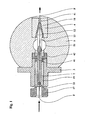
- the figure 1 represents a cladding device according to the invention.
- This device comprises a body 5 surrounding the central chamber 51 connected by a conduit to an extrusion means (not shown).
- the extrusion means has the function of supplying under pressure the central chamber of plastic or thermoplastic material in the viscous state.
- This means can be formed quite conventionally by an extruder comprising a screw disposed in a sheath whose rotational speed acts on the flow and pressure.
- the screw can also be designed to act on the plasticity and the viscosity of the material so as to deliver in the central chamber a material having the optimum characteristics for the purpose of sheathing the wire.
- extrusion means capable of delivering a pressurized material such as, for example, volumetric pumps of the gear type or the piston type.
- the device which is the subject of the present description is more particularly intended for sheathing a textile or metal wire or cable with a rubber material. It should be noted, however, that the device and method according to the invention can equally well, with the necessary adaptations to the characteristics of the materials used, be used for the sheathing of a wire by any other type of material having the viscosity characteristics. making it suitable for the sheathing operation. Thus, for the cladding of a wire by a thermoplastic material it will be necessary to take into account the thermal specificities of this material to bring it into the central chamber under the desired viscosity conditions.
- the body 5 is traversed from one side by the wire F which circulates at a given speed in the direction of the arrows passing successively through the wire guide 2, the central chamber 51 and the outlet die 4.
- the wire guide 2 is mounted on a support 3 itself secured to the body 5 by a set of screws (not shown). Its function is to center the wire at the entrance of the central chamber and to prevent the pressurized rubber present in said chamber from entering the guiding device.
- the wire guide is held on the support by two screws 23 inserted into the threads 22 as shown in FIG. figure 3 and at the figure 6 .
- the output section 21 of the wire guide is substantially equal to the section of the wire or son increased by 0.3 / 10 th of a millimeter. It will also be observed that the speed effect described above, combined with a small difference between the section of the wire and the exit section of the wire guide, act favorably to prevent the rubber present in the central chamber from coming out of the guide device. .
- the mobile die 12 is represented on the figure 1 in the "low speed" configuration, downstream of the central chamber 51 and upstream of the exit die 4.
- the shape of the mobile die 12 and of the exit die 4 are adapted so that these two dies fit into each other to reduce overall footprint.
- the outlet die 4 is fixed relative to the body 5.
- the surface of the wire is coated at the level of the central chamber 51, and the shape of the final section of the sheath is given by the calibration section S 2 located on the downstream portion 11 of the mobile die 12.
- the difference in diameter between the section S 1 and the section S 2 is of the order of 1 / 10 th to 2/10 th of a millimeter.
- the speed range can vary from 0 to 8m / s and the pressure range can be regulated without difficulty between 1 MPa and 20 MPa when it is desired to deposit on the surface of the wire a rubbery material forming a layer of a thickness 1/10 th of a millimeter,
- the mobile die 12 is driven in motion by an actuator connected to the rear part of the mobile die 12.
- the actuator passes through the central chamber 51 and the support 3, and has a front portion 13, an intermediate portion 15 and a head 17 as illustrated in the figure 4 .
- the front portion 13 of the actuator comprises a passage 14 allowing the circulation of the material from the central chamber 51 to the internal volume of the mobile die in which the wire F circulates when the device is in operation and the mobile die is placed in the "low speed" configuration.
- the intermediate portion 15 of the actuator slides freely in the support 3 and around the guide wire 2.
- longitudinal slots 16 are made on all the length of this portion 15, so as to allow the passage of the screws 23 intended to maintain the wire guide 2 in a fixed position and secured to the support 3.
- the rear part of the actuator comprises a head 17, intended to be connected to an animation mechanism (not shown) such as a pneumatic or hydraulic cylinder or an electric actuator such as a linear motor.
- an animation mechanism such as a pneumatic or hydraulic cylinder or an electric actuator such as a linear motor.
- the actuator is disposed upstream of the mobile die 12. Note that it is also possible to arrange the actuator downstream of the mobile die or to design a set of drawers suitable for driving the moving die in motion, and disposed on the side portion of the walls of the central chamber.
- a scraper 4 formed of two half-shells 41 and 42, as illustrated in FIG. figure 5 , is arranged on the front part of the support.
- the shape of the scraper is adapted to match the shape of the outer section of the front portion 13, 14 of the actuator.
- the scraper has the function of preventing the penetration of the material in the part of the support where the guide wire is arranged, and in which the actuator circulates when the actuator is moved between the upstream and downstream of the central chamber.
- the schematic view of the assembly comprising the support 3, containing the mobile die 12 provided with its actuator, the wire guide 2 and the scraper 41, 42 is illustrated in a perspective view at the figure 6 , and according to a sectional view at figure 7 .
- the figure 2 represents the cladding device in the so-called "high speed" configuration.
- the mobile die 12 is moved upstream of the device, the inner part of the mobile die is fitted around the end of the wire guide so as to clear the internal space of the central chamber 51 which is then in communication directly with the inner part of the exit die 4.
- the mobile die 12 is neutralized.
- the calibration of the wire is at the downstream portion 41 of the output die 4 whose section S 2 is greater than the section S 1 of the mobile die.
- the device which is the subject of the present description comprises a single mobile die 12 and an exit die 4. It is also possible, without departing from the spirit of the invention, to have several moving dies according to the direction of progression. of the wire, whose calibration section S i decreases according to their rank upstream of the exit die. This assembly, more complex, can solve the difficulties caused by the implementation of highly viscous materials or the realization of sheathing very thin.
- This description describes a device capable of sheathing a unitary yarn.
- the principles of the invention can also be applied when it is sought to coat a viscous material with a set of wires arranged side by side parallel to each other in the same plane and forming a sheet to obtain a strip of coated son.
- the section of the wire guide, the one or more mobile dies and the section of the exit die is elongate in the direction of the plane of the web perpendicular to the direction of progression, and adopts an oblong shape, adapted to the width of the sheet of son.
- the invention also relates to a method of sheathing by a plastic or thermoplastic material of one or more son and using the device that is the subject of the present description.
- the method consists in interposing at least one mobile die (12) of calibration section S 2 smaller than the calibration section S 1 of the exit die (4) between the central chamber (51) and the exit die (4). when the son or son circulate at reduced speed, and that the movable die (12) is brought upstream of the central chamber (51) when the son or son circulate at high speed.
- the movements of the (or) mobile die are controlled by the actuator.
- this actuator can itself be connected to an animation mechanism of the type of a pneumatic cylinder or a linear motor, and controlled by the control automation of the process.
- the arrival pressure regulating range of the material in the central chamber at a given speed and calibration section is the same as for a calibration section and a higher speed.
- a first method consists in maintaining the pressure level making it possible to obtain the desired cladding thickness for a given speed and a calibration section, and to perform a rapid movement of the mobile die combined with a rapid rise in speed, so as to end up at the speed and the corresponding upper calibration section, for the same pressure level, to the set point for obtaining a very thin sheathing thickness close to the thickness obtained at low speed in the previous configuration.
- the opposite process applies to move from high speed to low speed
- the movement of the mobile die can be extremely fast and that the dynamics of the system is primarily related to the dynamics of variation of speed of progression of the wire.
- the device and the method of use of the device according to the invention make it possible to have a means capable of producing a sheathed wire over a high speed range while maintaining a substantially constant cladding thickness. Also, the use of this device proves particularly advantageous when the device according to the invention is coupled to downstream industrial processes experiencing high instantaneous consumption variations and that we do not wish to increase the size of the buffer devices. placed between the sheathing device and the downstream process.
- the device and the method as described above make it possible to sheath a wire or a set of wires by depositing a sheath of substantially constant thickness irrespective of the speed of movement of the wire while regulating the pressure of the material in the central chamber. in a relatively small range.
- This method is used among other things to manufacture in large quantities a continuous wire sheathed in rubber, such as the son used for the realization of tires for vehicles.
- This same device can equally well be used for sheathing a wire by depositing a sheath of variable thickness, changing the calibration section at will and maintaining a speed of progression of the wire and a pressure of the material in the central chamber substantially constant. . Since the movement of the mobile die is almost instantaneous, it makes it possible to produce a yarn having different sheath thicknesses over given and predetermined lengths of thread.
- This application may be particularly advantageous when the wire is intended for example to be used as carcass reinforcing wire of a tire for which it is necessary to distinguish the cladding thicknesses of the part of the wire located in the lower zone and the part located in the summit area.
Landscapes
- Engineering & Computer Science (AREA)
- Mechanical Engineering (AREA)
- Manufacturing & Machinery (AREA)
- Textile Engineering (AREA)
- Extrusion Moulding Of Plastics Or The Like (AREA)
- Tyre Moulding (AREA)
- Ropes Or Cables (AREA)
- Manufacturing Of Electric Cables (AREA)
- Insulated Conductors (AREA)
- Flexible Shafts (AREA)
- Processing Of Terminals (AREA)
Applications Claiming Priority (1)
| Application Number | Priority Date | Filing Date | Title |
|---|---|---|---|
| FR0606977A FR2904256B1 (fr) | 2006-07-27 | 2006-07-27 | Dispositif de gainage de cable a filiere mobile |
Publications (2)
| Publication Number | Publication Date |
|---|---|
| EP1882578A1 EP1882578A1 (fr) | 2008-01-30 |
| EP1882578B1 true EP1882578B1 (fr) | 2009-09-09 |
Family
ID=37776437
Family Applications (1)
| Application Number | Title | Priority Date | Filing Date |
|---|---|---|---|
| EP07110939A Active EP1882578B1 (fr) | 2006-07-27 | 2007-06-25 | Dispositif et procédé de gainage de câblé et le câble manufacturé |
Country Status (8)
| Country | Link |
|---|---|
| US (2) | US20080038392A1 (https=) |
| EP (1) | EP1882578B1 (https=) |
| JP (1) | JP5097941B2 (https=) |
| CN (1) | CN101112787B (https=) |
| AT (1) | ATE442238T1 (https=) |
| BR (1) | BRPI0703275B1 (https=) |
| DE (1) | DE602007002343D1 (https=) |
| FR (1) | FR2904256B1 (https=) |
Families Citing this family (13)
| Publication number | Priority date | Publication date | Assignee | Title |
|---|---|---|---|---|
| FI120823B (fi) * | 2007-12-10 | 2010-03-31 | Maillefer Sa | Järjestely suulakepuristusvälineiden yhteydessä |
| CN102394160A (zh) * | 2011-11-01 | 2012-03-28 | 江苏祥源电气设备有限公司 | 一种复合绝缘子挤包机 |
| SK7309Y1 (sk) * | 2014-09-03 | 2015-12-03 | Konstrukta Industry A S | Zariadenie na reguláciu parametrov povlakovacích hláv výstužných vlákien |
| GB2530113B (en) * | 2014-09-12 | 2017-05-03 | Asterope Ltd | Wire coating technique |
| JP6152867B2 (ja) * | 2015-04-06 | 2017-06-28 | 横浜ゴム株式会社 | ゴム押出部材の製造方法及び製造装置 |
| NL2016826B1 (en) * | 2016-05-25 | 2017-12-12 | Vmi Holland Bv | Extruder head for extruding cord-reinforced extrudate |
| EP3606722B1 (en) * | 2017-04-03 | 2021-05-26 | VMI Holland B.V. | Extruder system and method for extruding cord-reinforced tire components |
| JP6868194B2 (ja) * | 2017-05-30 | 2021-05-12 | 日立金属株式会社 | 調心機構付きダイス、エナメル線の製造装置およびエナメル線の製造方法 |
| US12403503B1 (en) | 2019-10-02 | 2025-09-02 | Tau Act Gmbh | Method and control system for applying a polymer coating material to a wire using a coating apparatus |
| CN114360815B (zh) * | 2022-01-25 | 2024-01-12 | 先登高科电气股份有限公司 | 一种高自由度的自定中心涂漆模具 |
| CN114789548A (zh) * | 2022-04-02 | 2022-07-26 | 宝胜科技创新股份有限公司 | 一种电线电缆挤塑调偏辅助装置及调偏方法 |
| IT202300015501A1 (it) | 2023-07-24 | 2025-01-24 | Tre Tau Eng S R L | Metodo e dispositivo per controllare i parametri geometrici di un filo rivestito |
| US20250187278A1 (en) * | 2023-12-12 | 2025-06-12 | The Goodyear Tire & Rubber Company | Method and machine for manufacturing a cord-reinforced elastomer composition band |
Family Cites Families (27)
| Publication number | Priority date | Publication date | Assignee | Title |
|---|---|---|---|---|
| US1859901A (en) * | 1929-09-11 | 1932-05-24 | Bell Telephone Labor Inc | Extruding apparatus |
| US1911858A (en) * | 1930-12-03 | 1933-05-30 | Bell Telephone Labor Inc | Extrusion die |
| DE713693C (de) * | 1937-12-17 | 1941-11-13 | Kabelwerk Vacha A G | Pressmundstueck fuer Schlauchmaschinen |
| US3815640A (en) * | 1972-01-13 | 1974-06-11 | Takiron Co | Elongated pipe tightly coated with a projection-formed synthetic resin coating |
| DE2457249C3 (de) * | 1974-12-04 | 1979-05-17 | Reifenhaeuser Kg, 5210 Troisdorf | Querspritzkopf für einen Extruder zum Ummanteln eines Kabels |
| JPS51107863U (https=) * | 1975-02-28 | 1976-08-28 | ||
| US4093414A (en) * | 1976-09-16 | 1978-06-06 | General Cable Corporation | Single die co-extrusion apparatus for insulation |
| JPS57207046A (en) * | 1981-06-16 | 1982-12-18 | Fujikura Ltd | Method of adjusting thickness deviation of extrusion crosshead and apparatus therefor |
| JPS60110422A (ja) * | 1983-11-19 | 1985-06-15 | Kobe Steel Ltd | 線条物被覆用クロスヘツド |
| US4568507A (en) * | 1983-12-27 | 1986-02-04 | Northern Telecom Limited | Jacketing of telecommunications cable cores |
| JPS62123045A (ja) * | 1985-11-25 | 1987-06-04 | Sumitomo Electric Ind Ltd | 線材被覆装置 |
| JPS62222824A (ja) * | 1986-03-25 | 1987-09-30 | Kinugawa Rubber Ind Co Ltd | 芯材入りウエザ−ストリツプの製造装置 |
| US5169548A (en) * | 1988-04-13 | 1992-12-08 | Ausimont S.R.L. | Antirust additives for lubricants or greases based on perfluoropolyethers |
| US5215698A (en) * | 1991-11-25 | 1993-06-01 | Americraft Machined Products, Inc. | Extrusion tool and method of extrusion coating |
| US5674318A (en) * | 1994-10-11 | 1997-10-07 | Milliman; James A. | Cross-head die apparatus |
| FI105391B (fi) * | 1996-04-04 | 2000-08-15 | Nextrom Holding Sa | Menetelmä ja laite suulakepuristettavan tuotteen tekemiseksi |
| JP3206439B2 (ja) * | 1996-06-28 | 2001-09-10 | 東海興業株式会社 | モールディングの製造方法及び装置 |
| JP2002046190A (ja) * | 2000-08-03 | 2002-02-12 | Bridgestone Corp | ゴム−補強素子複合体とその製造装置及び方法並びに空気入りタイヤ |
| WO2002020898A2 (en) * | 2000-08-30 | 2002-03-14 | Owens Corning | Die for making composite cable |
| US7323055B2 (en) * | 2002-01-29 | 2008-01-29 | Matsushita Electric Industrial Co., Ltd. | Extrusion head for extruding a high viscous melting covering element of a covered core wire |
| US20050102929A1 (en) * | 2002-07-26 | 2005-05-19 | Hoffmann David J. | Seal for a loading dock bumper |
| JP4730881B2 (ja) * | 2004-10-14 | 2011-07-20 | 株式会社ブリヂストン | ゴム被覆ヘッド |
| FR2879500A1 (fr) * | 2004-12-22 | 2006-06-23 | Michelin Soc Tech | Procede et dispositif pour la fabrication et la pose d'un renforcement circonferentiel pour pneumatique et pneumatique obtenu par ledit procede |
| CA2596134C (en) * | 2005-01-28 | 2015-07-21 | Mmr Marketing & Management Ag Rotkreuz | Extruder system for extruding a fluid |
| US8147739B2 (en) * | 2005-04-27 | 2012-04-03 | Prysmian Cavi E Sistemi Energia S.R.L. | Cable manufacturing process |
| WO2006114117A1 (en) * | 2005-04-27 | 2006-11-02 | Pirelli Tyre S.P.A. | Method for extruding a polymeric material and extrusion head therefor |
| TW200926767A (en) * | 2007-12-07 | 2009-06-16 | Sunplus Mmedia Inc | Automatic flicker detection and correction apparatus and method in a video capture device |
-
2006
- 2006-07-27 FR FR0606977A patent/FR2904256B1/fr not_active Expired - Fee Related
-
2007
- 2007-06-25 EP EP07110939A patent/EP1882578B1/fr active Active
- 2007-06-25 DE DE602007002343T patent/DE602007002343D1/de active Active
- 2007-06-25 AT AT07110939T patent/ATE442238T1/de not_active IP Right Cessation
- 2007-07-18 CN CN200710136112XA patent/CN101112787B/zh active Active
- 2007-07-25 BR BRPI0703275-7A patent/BRPI0703275B1/pt active IP Right Grant
- 2007-07-26 US US11/881,638 patent/US20080038392A1/en not_active Abandoned
- 2007-07-27 JP JP2007217605A patent/JP5097941B2/ja not_active Expired - Fee Related
-
2011
- 2011-05-20 US US13/112,553 patent/US20110220254A1/en not_active Abandoned
Also Published As
| Publication number | Publication date |
|---|---|
| EP1882578A1 (fr) | 2008-01-30 |
| FR2904256B1 (fr) | 2008-11-21 |
| BRPI0703275A (pt) | 2008-03-11 |
| CN101112787B (zh) | 2011-07-27 |
| BRPI0703275A8 (pt) | 2017-12-19 |
| DE602007002343D1 (de) | 2009-10-22 |
| ATE442238T1 (de) | 2009-09-15 |
| JP5097941B2 (ja) | 2012-12-12 |
| FR2904256A1 (fr) | 2008-02-01 |
| JP2008030485A (ja) | 2008-02-14 |
| US20080038392A1 (en) | 2008-02-14 |
| CN101112787A (zh) | 2008-01-30 |
| US20110220254A1 (en) | 2011-09-15 |
| BRPI0703275B1 (pt) | 2018-01-23 |
Similar Documents
| Publication | Publication Date | Title |
|---|---|---|
| EP1882578B1 (fr) | Dispositif et procédé de gainage de câblé et le câble manufacturé | |
| EP0803878B1 (fr) | Procédé et dispositif de fabrication d'une gaine aérée en un matériau isolant autour d'un conducteur, et câble coaxial muni d'une telle gaine | |
| FR2520266A1 (fr) | Procede et dispositif de revetement de fibre optique | |
| EP1123194A1 (fr) | Corps de revolution creux et son procede de fabrication | |
| FR2515411A1 (fr) | Procede et dispositif de fabrication d'un jonc a rainures helicoidales pour cable a fibres optiques et le jonc obtenu selon le procede | |
| FR2919750A1 (fr) | Cable coaxial a faible constante dielectrique, et ses procede et outil de fabrication | |
| FR3074081A1 (fr) | Procede et installation de bobinage d'une bande de tissu pre-impregnee sur une surface inclinee | |
| FR2508374A1 (fr) | Procede permettant de former des rainures longitudinales sur un filament en materiau thermoplastique ou a la surface d'un corps cylindrique allonge | |
| EP1517781A1 (fr) | Appareil de fabrication d une structure de renforcement pour pneumatique, comprenant un mecanisme de retournement de la bandelette | |
| EP1720690B1 (fr) | Dose multicouche et son procede de fabrication | |
| EP0274317B1 (fr) | Procédé et installation d'extrusion d'un produit en forme de film, de plaque, de tube, de tige ou de fil | |
| EP3272507B1 (fr) | Procédé d'obtention d'une pièce profilée courbe en matière composite et/ou synthétique, et dispositif de mise en oeuvre de ce procédé | |
| EP3162533B1 (fr) | Installation pour la fabrication d'un revêtement de protection thermique d'un corps ou d'un ensemble arrière de propulseur et procédés associés | |
| EP2928675B1 (fr) | Dispositif d'impregnation, unite de fabrication d'un profile creux par pultrusion comprenant un tel dispositif et procede de fabrication correspondant | |
| EP3160710B1 (fr) | Procédé et dispositif de fabrication de fil métallique enrobé de caoutchouc | |
| EP2803458B1 (fr) | Procédé de réalisation d'une préforme de fibres par enroulement et outillage pour mettre en oeuvre ledit procédé | |
| WO2005072051A2 (fr) | Systeme de dosage de matiere plastique pour dispositif de production d'articles en matiere plastique | |
| EP3853001A1 (fr) | Machine de coextrusion pour melanges elastomeriques et procédé de fabrication de bande de profilé | |
| EP2047962A1 (fr) | Dispositif de gainage d'une nappe de fils à canaux d'alimentation symétriques | |
| EP0122828A1 (fr) | Produit hélicoidal du type ressort en matière plastique et son procédé et dispositif d'obtention | |
| EP1282502B1 (fr) | Distributeur de matiere dans une tete d'extrusion et tete d'extrusion utilisant ce distributeur | |
| EP2675614A1 (fr) | Ammenagement de la section d'une bandelette extrudee | |
| BE680627A (https=) | ||
| BE613103A (https=) | ||
| WO2013160013A1 (fr) | Machine et procédé de fabrication par extrusion de tuyaux d'irrigation |
Legal Events
| Date | Code | Title | Description |
|---|---|---|---|
| PUAI | Public reference made under article 153(3) epc to a published international application that has entered the european phase |
Free format text: ORIGINAL CODE: 0009012 |
|
| AK | Designated contracting states |
Kind code of ref document: A1 Designated state(s): AT BE BG CH CY CZ DE DK EE ES FI FR GB GR HU IE IS IT LI LT LU LV MC MT NL PL PT RO SE SI SK TR |
|
| AX | Request for extension of the european patent |
Extension state: AL BA HR MK YU |
|
| 17P | Request for examination filed |
Effective date: 20080730 |
|
| 17Q | First examination report despatched |
Effective date: 20080904 |
|
| AKX | Designation fees paid |
Designated state(s): AT BE BG CH CY CZ DE DK EE ES FI FR GB GR HU IE IS IT LI LT LU LV MC MT NL PL PT RO SE SI SK TR |
|
| GRAP | Despatch of communication of intention to grant a patent |
Free format text: ORIGINAL CODE: EPIDOSNIGR1 |
|
| GRAS | Grant fee paid |
Free format text: ORIGINAL CODE: EPIDOSNIGR3 |
|
| GRAA | (expected) grant |
Free format text: ORIGINAL CODE: 0009210 |
|
| AK | Designated contracting states |
Kind code of ref document: B1 Designated state(s): AT BE BG CH CY CZ DE DK EE ES FI FR GB GR HU IE IS IT LI LT LU LV MC MT NL PL PT RO SE SI SK TR |
|
| REG | Reference to a national code |
Ref country code: GB Ref legal event code: FG4D Free format text: NOT ENGLISH |
|
| REG | Reference to a national code |
Ref country code: CH Ref legal event code: EP |
|
| REG | Reference to a national code |
Ref country code: IE Ref legal event code: FG4D |
|
| REF | Corresponds to: |
Ref document number: 602007002343 Country of ref document: DE Date of ref document: 20091022 Kind code of ref document: P |
|
| PG25 | Lapsed in a contracting state [announced via postgrant information from national office to epo] |
Ref country code: SE Free format text: LAPSE BECAUSE OF FAILURE TO SUBMIT A TRANSLATION OF THE DESCRIPTION OR TO PAY THE FEE WITHIN THE PRESCRIBED TIME-LIMIT Effective date: 20090909 Ref country code: FI Free format text: LAPSE BECAUSE OF FAILURE TO SUBMIT A TRANSLATION OF THE DESCRIPTION OR TO PAY THE FEE WITHIN THE PRESCRIBED TIME-LIMIT Effective date: 20090909 Ref country code: LT Free format text: LAPSE BECAUSE OF FAILURE TO SUBMIT A TRANSLATION OF THE DESCRIPTION OR TO PAY THE FEE WITHIN THE PRESCRIBED TIME-LIMIT Effective date: 20090909 |
|
| NLV1 | Nl: lapsed or annulled due to failure to fulfill the requirements of art. 29p and 29m of the patents act | ||
| LTIE | Lt: invalidation of european patent or patent extension |
Effective date: 20090909 |
|
| PG25 | Lapsed in a contracting state [announced via postgrant information from national office to epo] |
Ref country code: LV Free format text: LAPSE BECAUSE OF FAILURE TO SUBMIT A TRANSLATION OF THE DESCRIPTION OR TO PAY THE FEE WITHIN THE PRESCRIBED TIME-LIMIT Effective date: 20090909 Ref country code: SI Free format text: LAPSE BECAUSE OF FAILURE TO SUBMIT A TRANSLATION OF THE DESCRIPTION OR TO PAY THE FEE WITHIN THE PRESCRIBED TIME-LIMIT Effective date: 20090909 Ref country code: NL Free format text: LAPSE BECAUSE OF FAILURE TO SUBMIT A TRANSLATION OF THE DESCRIPTION OR TO PAY THE FEE WITHIN THE PRESCRIBED TIME-LIMIT Effective date: 20090909 Ref country code: PL Free format text: LAPSE BECAUSE OF FAILURE TO SUBMIT A TRANSLATION OF THE DESCRIPTION OR TO PAY THE FEE WITHIN THE PRESCRIBED TIME-LIMIT Effective date: 20090909 |
|
| PG25 | Lapsed in a contracting state [announced via postgrant information from national office to epo] |
Ref country code: CY Free format text: LAPSE BECAUSE OF FAILURE TO SUBMIT A TRANSLATION OF THE DESCRIPTION OR TO PAY THE FEE WITHIN THE PRESCRIBED TIME-LIMIT Effective date: 20090909 |
|
| REG | Reference to a national code |
Ref country code: IE Ref legal event code: FD4D |
|
| PG25 | Lapsed in a contracting state [announced via postgrant information from national office to epo] |
Ref country code: RO Free format text: LAPSE BECAUSE OF FAILURE TO SUBMIT A TRANSLATION OF THE DESCRIPTION OR TO PAY THE FEE WITHIN THE PRESCRIBED TIME-LIMIT Effective date: 20090909 Ref country code: PT Free format text: LAPSE BECAUSE OF FAILURE TO SUBMIT A TRANSLATION OF THE DESCRIPTION OR TO PAY THE FEE WITHIN THE PRESCRIBED TIME-LIMIT Effective date: 20100111 Ref country code: IE Free format text: LAPSE BECAUSE OF FAILURE TO SUBMIT A TRANSLATION OF THE DESCRIPTION OR TO PAY THE FEE WITHIN THE PRESCRIBED TIME-LIMIT Effective date: 20090909 Ref country code: ES Free format text: LAPSE BECAUSE OF FAILURE TO SUBMIT A TRANSLATION OF THE DESCRIPTION OR TO PAY THE FEE WITHIN THE PRESCRIBED TIME-LIMIT Effective date: 20091220 Ref country code: EE Free format text: LAPSE BECAUSE OF FAILURE TO SUBMIT A TRANSLATION OF THE DESCRIPTION OR TO PAY THE FEE WITHIN THE PRESCRIBED TIME-LIMIT Effective date: 20090909 Ref country code: CZ Free format text: LAPSE BECAUSE OF FAILURE TO SUBMIT A TRANSLATION OF THE DESCRIPTION OR TO PAY THE FEE WITHIN THE PRESCRIBED TIME-LIMIT Effective date: 20090909 Ref country code: IS Free format text: LAPSE BECAUSE OF FAILURE TO SUBMIT A TRANSLATION OF THE DESCRIPTION OR TO PAY THE FEE WITHIN THE PRESCRIBED TIME-LIMIT Effective date: 20100109 |
|
| PG25 | Lapsed in a contracting state [announced via postgrant information from national office to epo] |
Ref country code: SK Free format text: LAPSE BECAUSE OF FAILURE TO SUBMIT A TRANSLATION OF THE DESCRIPTION OR TO PAY THE FEE WITHIN THE PRESCRIBED TIME-LIMIT Effective date: 20090909 |
|
| PG25 | Lapsed in a contracting state [announced via postgrant information from national office to epo] |
Ref country code: AT Free format text: LAPSE BECAUSE OF FAILURE TO SUBMIT A TRANSLATION OF THE DESCRIPTION OR TO PAY THE FEE WITHIN THE PRESCRIBED TIME-LIMIT Effective date: 20090909 |
|
| PLBE | No opposition filed within time limit |
Free format text: ORIGINAL CODE: 0009261 |
|
| STAA | Information on the status of an ep patent application or granted ep patent |
Free format text: STATUS: NO OPPOSITION FILED WITHIN TIME LIMIT |
|
| PG25 | Lapsed in a contracting state [announced via postgrant information from national office to epo] |
Ref country code: DK Free format text: LAPSE BECAUSE OF FAILURE TO SUBMIT A TRANSLATION OF THE DESCRIPTION OR TO PAY THE FEE WITHIN THE PRESCRIBED TIME-LIMIT Effective date: 20090909 |
|
| 26N | No opposition filed |
Effective date: 20100610 |
|
| PG25 | Lapsed in a contracting state [announced via postgrant information from national office to epo] |
Ref country code: GR Free format text: LAPSE BECAUSE OF FAILURE TO SUBMIT A TRANSLATION OF THE DESCRIPTION OR TO PAY THE FEE WITHIN THE PRESCRIBED TIME-LIMIT Effective date: 20091210 |
|
| BERE | Be: lapsed |
Owner name: MICHELIN RECHERCHE ET TECHNIQUE S.A. Effective date: 20100630 Owner name: SOC. DE TECHNOLOGIE MICHELIN Effective date: 20100630 |
|
| PG25 | Lapsed in a contracting state [announced via postgrant information from national office to epo] |
Ref country code: MC Free format text: LAPSE BECAUSE OF NON-PAYMENT OF DUE FEES Effective date: 20100630 |
|
| PG25 | Lapsed in a contracting state [announced via postgrant information from national office to epo] |
Ref country code: IT Free format text: LAPSE BECAUSE OF NON-PAYMENT OF DUE FEES Effective date: 20100625 |
|
| PG25 | Lapsed in a contracting state [announced via postgrant information from national office to epo] |
Ref country code: MT Free format text: LAPSE BECAUSE OF FAILURE TO SUBMIT A TRANSLATION OF THE DESCRIPTION OR TO PAY THE FEE WITHIN THE PRESCRIBED TIME-LIMIT Effective date: 20090909 |
|
| PG25 | Lapsed in a contracting state [announced via postgrant information from national office to epo] |
Ref country code: BE Free format text: LAPSE BECAUSE OF NON-PAYMENT OF DUE FEES Effective date: 20100630 |
|
| REG | Reference to a national code |
Ref country code: CH Ref legal event code: PL |
|
| GBPC | Gb: european patent ceased through non-payment of renewal fee |
Effective date: 20110625 |
|
| PG25 | Lapsed in a contracting state [announced via postgrant information from national office to epo] |
Ref country code: LI Free format text: LAPSE BECAUSE OF NON-PAYMENT OF DUE FEES Effective date: 20110630 Ref country code: CH Free format text: LAPSE BECAUSE OF NON-PAYMENT OF DUE FEES Effective date: 20110630 |
|
| PG25 | Lapsed in a contracting state [announced via postgrant information from national office to epo] |
Ref country code: GB Free format text: LAPSE BECAUSE OF NON-PAYMENT OF DUE FEES Effective date: 20110625 |
|
| PG25 | Lapsed in a contracting state [announced via postgrant information from national office to epo] |
Ref country code: HU Free format text: LAPSE BECAUSE OF FAILURE TO SUBMIT A TRANSLATION OF THE DESCRIPTION OR TO PAY THE FEE WITHIN THE PRESCRIBED TIME-LIMIT Effective date: 20100310 Ref country code: BG Free format text: LAPSE BECAUSE OF FAILURE TO SUBMIT A TRANSLATION OF THE DESCRIPTION OR TO PAY THE FEE WITHIN THE PRESCRIBED TIME-LIMIT Effective date: 20090909 Ref country code: LU Free format text: LAPSE BECAUSE OF NON-PAYMENT OF DUE FEES Effective date: 20100625 |
|
| PG25 | Lapsed in a contracting state [announced via postgrant information from national office to epo] |
Ref country code: TR Free format text: LAPSE BECAUSE OF FAILURE TO SUBMIT A TRANSLATION OF THE DESCRIPTION OR TO PAY THE FEE WITHIN THE PRESCRIBED TIME-LIMIT Effective date: 20090909 |
|
| REG | Reference to a national code |
Ref country code: FR Ref legal event code: PLFP Year of fee payment: 10 |
|
| REG | Reference to a national code |
Ref country code: FR Ref legal event code: PLFP Year of fee payment: 11 |
|
| REG | Reference to a national code |
Ref country code: FR Ref legal event code: PLFP Year of fee payment: 12 |
|
| REG | Reference to a national code |
Ref country code: DE Ref legal event code: R079 Ref document number: 602007002343 Country of ref document: DE Free format text: PREVIOUS MAIN CLASS: B29C0047220000 Ipc: B29C0048325000 |
|
| REG | Reference to a national code |
Ref country code: DE Ref legal event code: R081 Ref document number: 602007002343 Country of ref document: DE Owner name: COMPAGNIE GENERALE DES ETABLISSEMENTS MICHELIN, FR Free format text: FORMER OWNERS: SOCIETE DE TECHNOLOGIE MICHELIN, CLERMONT-FERRAND, FR; MICHELIN RECHERCHE ET TECHNIQUE S.A., GRANGES-PACCOT, CH |
|
| PGFP | Annual fee paid to national office [announced via postgrant information from national office to epo] |
Ref country code: DE Payment date: 20250618 Year of fee payment: 19 |
|
| PGFP | Annual fee paid to national office [announced via postgrant information from national office to epo] |
Ref country code: FR Payment date: 20250620 Year of fee payment: 19 |
|
| PGFP | Annual fee paid to national office [announced via postgrant information from national office to epo] |
Ref country code: IT Payment date: 20250624 Year of fee payment: 19 |