EP1878633A2 - Anordnung zum Aufnehmen und Übergeben und/oder Transportieren wenigstens eines Funktionsteils einer technischen Einrichtung - Google Patents
Anordnung zum Aufnehmen und Übergeben und/oder Transportieren wenigstens eines Funktionsteils einer technischen Einrichtung Download PDFInfo
- Publication number
- EP1878633A2 EP1878633A2 EP07010202A EP07010202A EP1878633A2 EP 1878633 A2 EP1878633 A2 EP 1878633A2 EP 07010202 A EP07010202 A EP 07010202A EP 07010202 A EP07010202 A EP 07010202A EP 1878633 A2 EP1878633 A2 EP 1878633A2
- Authority
- EP
- European Patent Office
- Prior art keywords
- chassis
- arrangement according
- technical device
- technical
- wheels
- Prior art date
- Legal status (The legal status is an assumption and is not a legal conclusion. Google has not performed a legal analysis and makes no representation as to the accuracy of the status listed.)
- Granted
Links
Images


Classifications
-
- B—PERFORMING OPERATIONS; TRANSPORTING
- B62—LAND VEHICLES FOR TRAVELLING OTHERWISE THAN ON RAILS
- B62B—HAND-PROPELLED VEHICLES, e.g. HAND CARTS OR PERAMBULATORS; SLEDGES
- B62B3/00—Hand carts having more than one axis carrying transport wheels; Steering devices therefor; Equipment therefor
- B62B3/002—Hand carts having more than one axis carrying transport wheels; Steering devices therefor; Equipment therefor characterised by a rectangular shape, involving sidewalls or racks
-
- B—PERFORMING OPERATIONS; TRANSPORTING
- B62—LAND VEHICLES FOR TRAVELLING OTHERWISE THAN ON RAILS
- B62B—HAND-PROPELLED VEHICLES, e.g. HAND CARTS OR PERAMBULATORS; SLEDGES
- B62B3/00—Hand carts having more than one axis carrying transport wheels; Steering devices therefor; Equipment therefor
- B62B3/04—Hand carts having more than one axis carrying transport wheels; Steering devices therefor; Equipment therefor involving means for grappling or securing in place objects to be carried; Loading or unloading equipment
- B62B3/06—Hand carts having more than one axis carrying transport wheels; Steering devices therefor; Equipment therefor involving means for grappling or securing in place objects to be carried; Loading or unloading equipment for simply clearing the load from the ground
- B62B3/0643—Hand carts having more than one axis carrying transport wheels; Steering devices therefor; Equipment therefor involving means for grappling or securing in place objects to be carried; Loading or unloading equipment for simply clearing the load from the ground the wheels remaining stationary while the supporting surface is lifted
-
- B—PERFORMING OPERATIONS; TRANSPORTING
- B29—WORKING OF PLASTICS; WORKING OF SUBSTANCES IN A PLASTIC STATE IN GENERAL
- B29C—SHAPING OR JOINING OF PLASTICS; SHAPING OF MATERIAL IN A PLASTIC STATE, NOT OTHERWISE PROVIDED FOR; AFTER-TREATMENT OF THE SHAPED PRODUCTS, e.g. REPAIRING
- B29C65/00—Joining or sealing of preformed parts, e.g. welding of plastics materials; Apparatus therefor
- B29C65/02—Joining or sealing of preformed parts, e.g. welding of plastics materials; Apparatus therefor by heating, with or without pressure
-
- B—PERFORMING OPERATIONS; TRANSPORTING
- B29—WORKING OF PLASTICS; WORKING OF SUBSTANCES IN A PLASTIC STATE IN GENERAL
- B29C—SHAPING OR JOINING OF PLASTICS; SHAPING OF MATERIAL IN A PLASTIC STATE, NOT OTHERWISE PROVIDED FOR; AFTER-TREATMENT OF THE SHAPED PRODUCTS, e.g. REPAIRING
- B29C66/00—General aspects of processes or apparatus for joining preformed parts
- B29C66/50—General aspects of joining tubular articles; General aspects of joining long products, i.e. bars or profiled elements; General aspects of joining single elements to tubular articles, hollow articles or bars; General aspects of joining several hollow-preforms to form hollow or tubular articles
- B29C66/51—Joining tubular articles, profiled elements or bars; Joining single elements to tubular articles, hollow articles or bars; Joining several hollow-preforms to form hollow or tubular articles
- B29C66/53—Joining single elements to tubular articles, hollow articles or bars
- B29C66/534—Joining single elements to open ends of tubular or hollow articles or to the ends of bars
- B29C66/5346—Joining single elements to open ends of tubular or hollow articles or to the ends of bars said single elements being substantially flat
- B29C66/53461—Joining single elements to open ends of tubular or hollow articles or to the ends of bars said single elements being substantially flat joining substantially flat covers and/or substantially flat bottoms to open ends of container bodies
-
- B—PERFORMING OPERATIONS; TRANSPORTING
- B29—WORKING OF PLASTICS; WORKING OF SUBSTANCES IN A PLASTIC STATE IN GENERAL
- B29C—SHAPING OR JOINING OF PLASTICS; SHAPING OF MATERIAL IN A PLASTIC STATE, NOT OTHERWISE PROVIDED FOR; AFTER-TREATMENT OF THE SHAPED PRODUCTS, e.g. REPAIRING
- B29C66/00—General aspects of processes or apparatus for joining preformed parts
- B29C66/80—General aspects of machine operations or constructions and parts thereof
- B29C66/81—General aspects of the pressing elements, i.e. the elements applying pressure on the parts to be joined in the area to be joined, e.g. the welding jaws or clamps
- B29C66/816—General aspects of the pressing elements, i.e. the elements applying pressure on the parts to be joined in the area to be joined, e.g. the welding jaws or clamps characterised by the mounting of the pressing elements, e.g. of the welding jaws or clamps
- B29C66/8167—Quick change joining tools or surfaces
-
- B—PERFORMING OPERATIONS; TRANSPORTING
- B29—WORKING OF PLASTICS; WORKING OF SUBSTANCES IN A PLASTIC STATE IN GENERAL
- B29C—SHAPING OR JOINING OF PLASTICS; SHAPING OF MATERIAL IN A PLASTIC STATE, NOT OTHERWISE PROVIDED FOR; AFTER-TREATMENT OF THE SHAPED PRODUCTS, e.g. REPAIRING
- B29C66/00—General aspects of processes or apparatus for joining preformed parts
- B29C66/80—General aspects of machine operations or constructions and parts thereof
- B29C66/83—General aspects of machine operations or constructions and parts thereof characterised by the movement of the joining or pressing tools
- B29C66/832—Reciprocating joining or pressing tools
- B29C66/8322—Joining or pressing tools reciprocating along one axis
-
- B—PERFORMING OPERATIONS; TRANSPORTING
- B29—WORKING OF PLASTICS; WORKING OF SUBSTANCES IN A PLASTIC STATE IN GENERAL
- B29C—SHAPING OR JOINING OF PLASTICS; SHAPING OF MATERIAL IN A PLASTIC STATE, NOT OTHERWISE PROVIDED FOR; AFTER-TREATMENT OF THE SHAPED PRODUCTS, e.g. REPAIRING
- B29C66/00—General aspects of processes or apparatus for joining preformed parts
- B29C66/80—General aspects of machine operations or constructions and parts thereof
- B29C66/84—Specific machine types or machines suitable for specific applications
- B29C66/841—Machines or tools adaptable for making articles of different dimensions or shapes or for making joints of different dimensions
-
- B—PERFORMING OPERATIONS; TRANSPORTING
- B29—WORKING OF PLASTICS; WORKING OF SUBSTANCES IN A PLASTIC STATE IN GENERAL
- B29C—SHAPING OR JOINING OF PLASTICS; SHAPING OF MATERIAL IN A PLASTIC STATE, NOT OTHERWISE PROVIDED FOR; AFTER-TREATMENT OF THE SHAPED PRODUCTS, e.g. REPAIRING
- B29C66/00—General aspects of processes or apparatus for joining preformed parts
- B29C66/80—General aspects of machine operations or constructions and parts thereof
- B29C66/84—Specific machine types or machines suitable for specific applications
- B29C66/843—Machines for making separate joints at the same time in different planes; Machines for making separate joints at the same time mounted in parallel or in series
- B29C66/8432—Machines for making separate joints at the same time mounted in parallel or in series
-
- B—PERFORMING OPERATIONS; TRANSPORTING
- B29—WORKING OF PLASTICS; WORKING OF SUBSTANCES IN A PLASTIC STATE IN GENERAL
- B29L—INDEXING SCHEME ASSOCIATED WITH SUBCLASS B29C, RELATING TO PARTICULAR ARTICLES
- B29L2031/00—Other particular articles
- B29L2031/712—Containers; Packaging elements or accessories, Packages
-
- B—PERFORMING OPERATIONS; TRANSPORTING
- B62—LAND VEHICLES FOR TRAVELLING OTHERWISE THAN ON RAILS
- B62B—HAND-PROPELLED VEHICLES, e.g. HAND CARTS OR PERAMBULATORS; SLEDGES
- B62B2203/00—Grasping, holding, supporting the objects
- B62B2203/10—Grasping, holding, supporting the objects comprising lifting means
Definitions
- the invention relates to an arrangement for receiving and transferring and / or transporting at least one functional part, in particular a tool, a technical device, in particular a device for automatically sealing containers, comprising at least one chassis carrying a functional part receiving device.
- a technical device is a device for automatically sealing containers
- this device has at least one tool for sealing the containers.
- this tool is a vacuum sealer that can be subdivided into a lower tool and an upper tool. With the lower tool to be sealed containers are guided against the upper tool, wherein between the containers and the upper tool a film is arranged, with which the containers are sealed.
- the lower tool is adapted to the shape of the container, on the other hand can be sealed with the lower tool and the upper tool from each other different numbers of containers in one operation.
- a chassis has been proposed, with which a tool can be added to a technical device can be delivered and can be transported.
- This chassis has sections that can be applied to an underside of a technical device.
- the invention is therefore an object of the invention to provide an arrangement of the type mentioned, which allows a transfer of functional parts on a chassis and vice versa universal in a variety of technical facilities.
- the arrangement comprises at least one arranged on the technical device stop element for the chassis and that at least one engageable with the stop element engaging the gripping element is arranged on the chassis.
- measures are provided on the technical device itself as on a chassis. Both components are equipped with means that allow a close contact of the chassis to the technical equipment.
- the chassis has a gripping element which can be brought into engagement with the stop element. As a result, a position-fixed assignment of the chassis to the technical equipment is possible.
- connection between the technical device and the chassis thus takes place above a floor of the technical device, namely where the stop elements are arranged on the technical device.
- These stop elements can be arranged on a variety of technical devices, so that a universal assignment of the chassis to technical facilities is possible. So that this position allocation is maintained stable for a longer period, for example, for the transfer or takeover of a tool, according to a first embodiment of the invention on the chassis at least one arranged on engagement of the gripping element to the technical device fitting element arranged.
- This investment element is applied to the technical equipment, but it is not necessary to invest in the underside of the technical equipment.
- the attachment to the technical equipment only serves to maintain a safe rest position when the gripping element is engaged with the stop element.
- the stop elements are formed, for example, as projections, while the gripping elements enclose the projections.
- the connection can nevertheless be carried out quickly in order not to delay the supply or removal of functional parts to the technical device or from the technical device.
- Each projection can be a bolt.
- each gripping element is a hook-in eye.
- This suspension eye can be easily hit on a bolt, in which it is simply hung.
- the stop elements for the chassis are preferably arranged in an upper region of a technical device.
- the gripping elements are then arranged in the same way in an upper portion of a chassis, so that the gripping of the stop elements is carried out by the gripping elements in the upper region of the chassis.
- the chassis is thus suspended in the upper part of the gripping elements quasi, by its lower center of gravity it is pressed against the technical device.
- the contact element is preferably initially arranged.
- the contact element is preferably designed as a contact surface, which is to be guided in a simple manner against a corresponding counter surface of a technical device and can rest against it.
- the contact element is arranged in a lower region of the chassis, so that it is located below the gripping elements accordingly.
- the chassis has wheels and that the wheels are added to the chassis height adjustable. With the wheels while the mobility of the chassis is guaranteed.
- the height variability of the wheels allows an adaptation of the chassis to various technical devices with arranged at different altitudes stop elements.
- front wheels and rear wheels of the chassis are combined into groups with common control of theircardinver applications.
- two front wheels together can be arranged higher or lower and are e.g. Rear wheels arranged together height adjustable.
- This separation ofcannver sections can then be exploited in a simplified approach to the technical device.
- the rear wheels front sections of the chassis tilted slightly forward. If the gripping elements are arranged in these front sections, they are guided slightly forward in order to facilitate gripping around the plug-in elements. Then then the rear wheels can be set lower again and all wheels are set so low that applies the contact element of the chassis to the technical equipment.
- Each wheel is preferably designed as a swivel castor with a 360 ° rotatability.
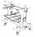
- the chassis in Fig. 1 is part of the arrangement according to the invention.
- the chassis has a composite of profiles frame structure 1.
- This frame structure 1 carries a functional part receiving device 2, with which, for example, a sealing tool of the technical device of FIG. 2 can be added.
- both suspension eyes 4 are arranged on the chassis. Both hooks 4 are connected to a bar profile 5 with each other to stabilize the defined distance between the two hooks 4.
- the frame structure 1 of the chassis stands on four wheels 6. Each wheel 6 is held vertically adjustable in a telescopic cylinder, which is arranged in a telescopic cylinder receptacle 7. By extension and retraction the 360 ° rotatable wheels 6, the height arrangement of the frame structure 1 changes over a ground, not shown.
- the technical device in Fig. 2 also has a frame 8.
- This frame 8 carries the functional parts of the technical device, inter alia an upper tool 9 and a lower tool 10.
- These tools 9, 10 serve to seal e.g. Peel.
- this tool 10 is suitable for receiving three shells in a sealing process. If other shells are to be sealed, the lower tool 10 and optionally the upper tool 9 can be seen from the technical device and replaced by another tool in each case.
- the technical device in Fig. 2 is equipped with bolts 11, which are also shown in Fig. 3.
- the bolts 11 project from an adjacent wall 12 of the technical device, so that they form a possibility of engagement for the suspension eyes 4.
- Fig. 4 shows the suspended state of the chassis to the technical device.
- the hooks 4 are brought into engagement with the bolts 11.
- the frame structure 1 is located with front telescopic cylinder shots 7 on the technical device. This system takes place in the technical device on the frame 8.
- chassis 7 contact surfaces 13 are provided on the front of the front telescopic cylinder mounts. These abutment surfaces 13 are e.g. formed by the front edges of the telescopic cylinder shots 7 top closing lid members 14.
Landscapes
- Engineering & Computer Science (AREA)
- Combustion & Propulsion (AREA)
- Transportation (AREA)
- Mechanical Engineering (AREA)
- Chemical & Material Sciences (AREA)
- Handcart (AREA)
- Closing Of Containers (AREA)
- Load-Engaging Elements For Cranes (AREA)
- Automatic Assembly (AREA)
- Multi-Process Working Machines And Systems (AREA)
- Automobile Manufacture Line, Endless Track Vehicle, Trailer (AREA)
- Sealing Of Jars (AREA)
- Refuse Receptacles (AREA)
- Refuse Collection And Transfer (AREA)
- Radar Systems Or Details Thereof (AREA)
- Containers And Plastic Fillers For Packaging (AREA)
- Specific Conveyance Elements (AREA)
Abstract
Description
- Die Erfindung betrifft eine Anordnung zum Aufnehmen und Übergeben und/oder Transportieren wenigstens eines Funktionsteils, insbesondere eines Werkzeuges, einer technischen Einrichtung, insbesondere einer Einrichtung zum automatischen Versiegeln von Behältern, umfassend wenigstens ein Fahrgestell, das eine Funktionsteilaufnahmeeinrichtung trägt.
- Technische Einrichtungen weisen verschiedene Funktionsteile auf. Handelt es sich bei einer technischen Einrichtung um eine Einrichtung zum automatischen Versiegeln von Behältern, so weist diese Einrichtung wenigstens ein Werkzeug zum Versiegeln der Behälter auf. Bei diesem Werkzeug handelt es sich beispielsweise um ein Folienschweißgerät, das in ein Unterwerkzeug und in ein Oberwerkzeug unterteilt sein kann. Mit dem Unterwerkzeug werden zu versiegelnde Behälter gegen das Oberwerkzeug geführt, wobei zwischen den Behältern und dem Oberwerkzeug eine Folie angeordnet ist, mit der die Behälter versiegelt werden.
- Für voneinander verschiedene Behälter kann das Verwenden voneinander verschiedener Werkzeuge erforderlich sein. Zum einen ist das Unterwerkzeug an die Form der Behälter angepaßt, zum anderen können mit dem Unterwerkzeug und mit dem Oberwerkzeug voneinander verschiedene Anzahlen von Behältern in einem Arbeitsgang versiegelt werden.
- Für das somit notwendige Wechseln der Werkzeuge einer Einrichtung ist in der
DE 102 09 000.9 ein Fahrgestell vorgeschlagen worden, mit dem ein Werkzeug aufgenommen werden kann, an eine technische Einrichtung abgegeben werden kann und transportiert werden kann. Dieses Fahrgestell weist Abschnitte auf, die an eine Unterseite einer technischen Einrichtung anlegbar sind. - Bei einer technischen Einrichtung, die im Bodenbereich keinen Freiraum zum Anlegen von derartigen Abschnitten aufweist, ist dieses bekannte Fahrgestell nicht ohne weiteres anwendbar.
- Der Erfindung liegt daher die Aufgabe zugrunde, eine Anordnung der eingangs genannten Gattung aufzuzeigen, die ein Überführen von Funktionsteilen auf ein Fahrgestell und umgekehrt universell bei einer Vielzahl von technischen Einrichtungen ermöglicht.
- Diese Aufgabe ist erfindungsgemäß dadurch gelöst, daß die Anordnung zumindest ein an der technischen Einrichtung angeordnetes Anschlagelement für das Fahrgestell umfaßt und daß an dem Fahrgestell zumindest ein mit dem Anschlagelement in Eingriff bringbares Greifelement angeordnet ist.
- Bei der erfindungsgemäßen Anordnung sind Maßnahmen an der technischen Einrichtung selbst wie an einem Fahrgestell vorgesehen. Beide Bauteile werden mit Mitteln ausgerüstet, die eine enge Anlage des Fahrgestelles an der technischen Einrichtung ermöglichen.
- An der technischen Einrichtung ist dazu das Anschlagelement angeordnet. Das Fahrgestell weist ein Greifelement auf, das mit dem Anschlagelement in Eingriff bringbar ist. Dadurch ist eine lagefeste Zuordnung des Fahrgestells zur technischen Einrichtung ermöglicht.
- Die Verbindung zwischen technischer Einrichtung und Fahrgestell findet somit oberhalb eines Bodens der technischen Einrichtung statt, nämlich dort, wo die Anschlagelemente an der technischen Einrichtung angeordnet sind. Diese Anschlagelemente können an den verschiedensten technischen Einrichtungen angeordnet sein, so daß eine universale Zuordnung des Fahrgestells zu technischen Einrichtungen ermöglicht ist. Damit diese Lagezuordnung auch über einen längeren Zeitraum z.B. für die Übergabe oder Übernahme eines Werkzeuges stabil erhalten bleibt, ist nach einer ersten Weiterbildung der Erfindung an dem Fahrgestell wenigstens ein bei Eingriff des Greifelementes an der technischen Einrichtung definiert anliegendes Anlageelement angeordnet. Dieses Anlageelement wird an die technische Einrichtung angelegt, dabei ist aber keine Anlage an der Unterseite der technischen Einrichtung notwendig. Die Anlage an der technischen Einrichtung dient nur noch dem Aufrechterhalten einer sicheren Ruheposition, wenn das Greifelement mit dem Anschlagelement in Eingriff steht.
- Die Anschlagelemente sind beispielsweise als Vorsprünge ausgebildet, während die Greifelemente die Vorsprünge hinterfassen. Durch das Hinterfassen von Vorsprüngen durch Greifelemente ist eine lagesichere Verbindung ermöglicht. Die Verbindung kann dabei gleichwohl schnell ausgeführt werden, um das Zuführen bzw. Wegführen von Funktionsteilen zu der technischen Einrichtung bzw. von der technischen Einrichtung nicht zu verzögern. Jeder Vorsprung kann dabei ein Bolzen sein.
- Um insbesondere das Anordnen der Greifelemente an den Vorsprüngen zu beschleunigen, ist nach einer Weiterbildung der Erfindung jedes Greifelement eine Einhängeöse. Diese Einhängeöse ist in einfacher Weise an einem Bolzen anschlagbar, in den sie einfach eingehängt wird.
- Die Anschlagelemente für das Fahrgestell sind vorzugsweise in einem oberen Bereich einer technischen Einrichtung angeordnet. Die Greifelemente sind dann in gleicher Weise in einem oberen Abschnitt eines Fahrgestells angeordnet, so daß das Ergreifen der Anschlagelemente durch die Greifelemente im oberen Bereich des Fahrgestelles erfolgt. Das Fahrgestell wird dadurch im oberen Bereich an den Greifelementen quasi aufgehängt, durch seinen tiefer angeordneten Schwerpunkt wird es gegen die technische Einrichtung gedrückt.
- In diesem Bereich der Anlage des Fahrgestells an der technischen Einrichtung ist zunächst vorzugsweise das Anlageelement angeordnet. Das Anlageelement ist vorzugsweise als Anlagefläche ausgebildet, welche in einfacher Weise gegen eine entsprechende Gegenfläche einer technischen Einrichtung zu führen ist und an dieser anliegen kann. Das Anlageelement ist dabei in einem unteren Bereich des Fahrgestells angeordnet, so daß es entsprechend unterhalb der Greifelemente befindlich ist.
- Zur weiteren Ausbildung der Erfindung ist noch vorgesehen, daß das Fahrgestell Räder hat und daß die Räder am Fahrgestell höhenveränderbar aufgenommen sind. Mit den Rädern ist dabei die Verfahrbarkeit des Fahrgestelles gewährleistet. Die Höhenveränderbarkeit der Räder ermöglicht eine Anpassung des Fahrgestells an verschiedene technische Einrichtungen mit in verschiedenen Höhenlagen angeordneten Anschlagelementen.
- Vorzugsweise sind jeweils in Annäherungsrichtung an die technischen Einrichtungen vorn angeordnete Räder und hinten angeordnete Räder des Fahrgestells zu Gruppen mit gemeinsamer Ansteuerung ihrer Höhenveränderbarkeit zusammengefaßt. Nach dieser Weiterbildung sind z.B. zwei vordere Räder gemeinsam höher oder tiefer anordbar und sind z.B. hinten angeordnete Räder gemeinsam höhenverstellbar. Diese Trennung der Höhenveränderbarkeit kann dann in einer vereinfachten Annäherung an die technische Einrichtung ausgenutzt werden. So sind durch eine stärkere Höherstellung der hinteren Räder vordere Abschnitte des Fahrgestells etwas nach vorn kippbar. Sind in diesen vorderen Abschnitten die Greifelemente angeordnet, so werden diese etwas nach vorn geführt, um ein Umgreifen der Einsteckelemente zu erleichtern. Anschließend können dann die hinteren Räder wieder niedriger eingestellt werden und alle Räder so niedrig eingestellt werden, daß sich das Anlageelement des Fahrgestells an die technische Einrichtung anlegt.
- Jedes Rad ist dabei vorzugsweise als Lenkrolle mit einer 360°-Drehbarkeit ausgebildet.
- Ein Ausführungsbeispiel der Erfindung, aus dem sich weitere erfinderische Merkmale ergeben, ist in der Zeichnung dargestellt. Es zeigen:
- Fig. 1:
- eine perspektivische Ansicht eines Fahrgestells mit einer Funktionsteilaufnahmeeinrichtung,
- Fig. 2:
- eine perspektivische Ansicht einer Einrichtung zum automatischen Versiegeln von Behältern und
- Fig. 3:
- eine maßstäblich vergrößerte Ansicht der Einzelheit III in Fig. 2 und
- Fig. 4:
- eine perspektivische Ansicht der technischen Einrichtung gemäß Fig. 2 und des Fahrgestells gemäß Fig. 1 bei Anlage des Fahrgestells an der technischen Einrichtung.
- Das Fahrgestell in Fig. 1 ist Teil der erfindungsgemäßen Anordnung. Das Fahrgestell weist einen aus Profilen zusammengesetzten Gestellaufbau 1 auf. Dieser Gestellaufbau 1 trägt eine Funktionsteilaufnahmeeinrichtung 2, mit welcher beispielsweise ein Siegelwerkzeug der technischen Einrichtung nach Fig. 2 aufgenommen werden kann.
- An Seitenwänden 3 des Gestellaufbaus 1 sind an dem Fahrgestell zwei Einhängeösen 4 angeordnet. Beide Einhängeösen 4 sind mit einem Stangenprofil 5 miteinander verbunden, um den definierten Abstand zwischen beiden Einhängeösen 4 zu stabilisieren.
- Der Gestellaufbau 1 des Fahrgestells steht auf vier Rädern 6 auf. Jedes Rad 6 ist höhenveränderbar in einem Teleskopzylinder gehalten, der in einer Teleskopzylinderaufnahme 7 angeordnet ist. Durch ein Aus- bzw. Einfahren der um 360° drehbaren Räder 6 verändert sich die Höhenanordnung des Gestellaufbaus 1 über einem nicht weiter dargestellten Boden.
- Die technische Einrichtung in Fig. 2 weist gleichfalls ein Gestell 8 auf. Dies Gestell 8 trägt die Funktionsteile der technischen Einrichtung, unter anderem ein Oberwerkzeug 9 und ein Unterwerkzeug 10. Diese Werkzeuge 9, 10 dienen dem Versiegeln von z.B. Schalen. Beim Unterwerkzeug 10 ist zu erkennen, daß dieses Werkzeug 10 für die Aufnahme von drei Schalen in einem Siegelvorgang geeignet ist. Wenn andere Schalen versiegelt werden sollen, ist das Unterwerkzeug 10 und gegebenenfalls das Oberwerkzeug 9 aus der technischen Einrichtung zu entnehmen und durch ein anderes Werkzeug jeweils zu ersetzen.
- Für eine Annäherung des Fahrgestells nach Fig. 1 ist die technische Einrichtung in Fig. 2 mit Bolzen 11 ausgerüstet, die auch in Fig. 3 dargestellt sind. Die Bolzen 11 stehen von einer benachbarten Wandung 12 der technischen Einrichtung vor, so daß sie eine Eingriffsmöglichkeit für die Einhängeösen 4 ausbilden.
- Fig. 4 zeigt den eingehängten Zustand des Fahrgestells an der technischen Einrichtung. Die Einhängeösen 4 sind mit den Bolzen 11 in Eingriff gebracht. Der Gestellaufbau 1 liegt mit vorderen Teleskopzylinderaufnahmen 7 an der technischen Einrichtung an. Diese Anlage erfolgt bei der technischen Einrichtung an dem Gestell 8. Beim Fahrgestell sind an der Vorderseite der vorderen Teleskopzylinderaufnahmen 7 Anlageflächen 13 vorgesehen. Diese Anlageflächen 13 sind z.B. durch die vorderen Kanten von den Teleskopzylinderaufnahmen 7 oben abschließenden Deckelelementen 14 ausgebildet.
Claims (11)
- Anordnung zum Aufnehmen und Übergeben und/oder Transportieren wenigstens eines Funktionsteils, insbesondere eines Werkzeuges, einer technischen Einrichtung, insbesondere einer Einrichtung zum automatischen Versiegeln von Behältern, umfassend wenigstens ein Fahrgestell, das eine Funktionsteilaufnahmeeinrichtung trägt,
dadurch gekennzeichnet,
daß sie zumindest ein an der technischen Einrichtung angeordnetes Anschlagelement für das Fahrgestell umfaßt und daß an dem Fahrgestell zumindest ein mit dem Anschlagelement in Eingriff bringbares Greifelement angeordnet ist. - Anordnung nach Anspruch 1, dadurch gekennzeichnet, daß an dem Fahrgestell wenigstens ein bei Eingriff des Greifelementes an der technischen Einrichtung definiert anliegendes Anlageelement angeordnet ist.
- Anordnung nach Anspruch 1 oder 2, dadurch gekennzeichnet, daß die Anschlagelemente als Vorsprünge ausgebildet sind und daß die Greifelemente die Vorsprünge hinterfassen.
- Anordnung nach Anspruch 3, dadurch gekennzeichnet, daß jeder Vorsprung ein Bolzen (11) ist.
- Anordnung nach Anspruch 3 oder 4, dadurch gekennzeichnet, daß jedes Greifelement eine Einhängeöse (4) ist.
- Anordnung nach einem der vorhergehenden Ansprüche, dadurch gekennzeichnet, daß das Greifelement in einem oberen Abschnitt des Fahrgestells angeordnet ist.
- Anordnung nach einem der vorhergehenden Ansprüche, dadurch gekennzeichnet, daß das Anlageelement des Fahrgestells eine Anlagefläche (13) ist.
- Anordnung nach einem der vorhergehenden Ansprüche, dadurch gekennzeichnet, daß das Anlageelement in einem unteren Bereich des Fahrgestells angeordnet ist.
- Anordnung nach einem der vorhergehenden Ansprüche, dadurch gekennzeichnet, daß das Fahrgestell Räder (6) hat und daß die Räder (6) am Fahrgestell höhenveränderbar aufgenommen sind.
- Anordnung nach Anspruch 9, dadurch gekennzeichnet, daß jeweils in Annäherungsrichtung an die technische Einrichtung vorne angeordnete Räder (6) und hinten angeordnete Räder (6) zu Gruppen mit gemeinsamer Ansteuerung ihrer Höhenveränderbarkeit zusammengefaßt sind.
- Anordnung nach Anspruch 9 oder 10, dadurch gekennzeichnet, daß jedes Rad (6) als Lenkrolle mit einer 360°-Drehbarkeit ausgebildet ist.
Priority Applications (2)
| Application Number | Priority Date | Filing Date | Title |
|---|---|---|---|
| PL07010202T PL1878633T3 (pl) | 2006-07-13 | 2007-05-23 | Układ do ustalania i przenoszenia i/lub transportowania co najmniej jednej części funkcjonalnej urządzenia technicznego |
| SI200730771T SI1878633T1 (sl) | 2006-07-13 | 2007-05-23 | Naprava za prijem, prenos in/ali transport vsaj enega funkcionalnega dela tehnične naprave |
Applications Claiming Priority (1)
| Application Number | Priority Date | Filing Date | Title |
|---|---|---|---|
| DE202006010803U DE202006010803U1 (de) | 2006-07-13 | 2006-07-13 | Anordnung zum Aufnehmen und Übergeben und/oder Transportieren wenigstens eines Funktionsteils einer technischen Einrichtung |
Publications (3)
| Publication Number | Publication Date |
|---|---|
| EP1878633A2 true EP1878633A2 (de) | 2008-01-16 |
| EP1878633A3 EP1878633A3 (de) | 2010-03-17 |
| EP1878633B1 EP1878633B1 (de) | 2011-08-31 |
Family
ID=37388180
Family Applications (1)
| Application Number | Title | Priority Date | Filing Date |
|---|---|---|---|
| EP07010202A Active EP1878633B1 (de) | 2006-07-13 | 2007-05-23 | Anordnung zum Aufnehmen und Übergeben und/oder Transportieren wenigstens eines Funktionsteils einer technischen Einrichtung |
Country Status (13)
| Country | Link |
|---|---|
| US (1) | US20080014072A1 (de) |
| EP (1) | EP1878633B1 (de) |
| AT (1) | ATE522422T1 (de) |
| AU (1) | AU2007203004B2 (de) |
| CA (1) | CA2593357A1 (de) |
| DE (1) | DE202006010803U1 (de) |
| DK (1) | DK1878633T3 (de) |
| ES (1) | ES2372870T3 (de) |
| NO (1) | NO332675B1 (de) |
| PL (1) | PL1878633T3 (de) |
| PT (1) | PT1878633E (de) |
| RU (1) | RU2433914C2 (de) |
| SI (1) | SI1878633T1 (de) |
Cited By (1)
| Publication number | Priority date | Publication date | Assignee | Title |
|---|---|---|---|---|
| EP3643631A1 (de) | 2018-10-26 | 2020-04-29 | MULTIVAC Sepp Haggenmüller SE & Co. KG | Verfahren und werkzeugwagen zum transferieren einer werkzeugkomponente |
Families Citing this family (11)
| Publication number | Priority date | Publication date | Assignee | Title |
|---|---|---|---|---|
| DE102007062983A1 (de) * | 2007-12-21 | 2009-06-25 | Ulma Packaging Gmbh | Verpackungsmaschine |
| DE102011101053B4 (de) | 2011-05-10 | 2014-06-05 | Multivac Sepp Haggenmüller Gmbh & Co. Kg | Arbeitsstation für eine Verpackungsmaschine und Verfahren zum Werkzeugwechsel |
| DE102011112658B4 (de) | 2011-09-06 | 2017-09-14 | Multivac Sepp Haggenmüller Se & Co. Kg | Andockvorrichtung für Werkzeugwechsel mittels eines Werkzeugwechselwagens |
| DE102011113968A1 (de) | 2011-09-21 | 2013-03-21 | Multivac Sepp Haggenmüller Gmbh & Co. Kg | Schalenverschließmaschine |
| GB201205150D0 (en) | 2012-03-23 | 2012-05-09 | Ishida Europ Ltd | Tool handling system |
| US20140129618A1 (en) * | 2012-11-08 | 2014-05-08 | General Instrument Corporation | Method of streaming multimedia data over a network |
| EP2907762A1 (de) | 2014-02-14 | 2015-08-19 | Multivac Sepp Haggenmüller GmbH & Co. KG | Werkzeugwechselwagen für Verpackungsmaschinen |
| US10427434B2 (en) | 2016-07-08 | 2019-10-01 | Xerox Corporation | Printing module replacement cart |
| US10279829B2 (en) * | 2016-07-15 | 2019-05-07 | Charles William Walkner | Ergonomic carts for metal forming operations |
| DE102019103196A1 (de) * | 2019-02-08 | 2020-08-13 | Buergofol GmbH | Unterwerkzeug für eine Skin-Verpackung |
| IT202000010156A1 (it) | 2020-05-07 | 2021-11-07 | Sasib Spa | Struttura per il supporto e trasporto di una pluralità di pezzi in operazioni di assemblaggio/disassemblaggio e/o di cambio configurazione in una linea manifatturiera |
Citations (2)
| Publication number | Priority date | Publication date | Assignee | Title |
|---|---|---|---|---|
| US6454512B1 (en) | 1999-03-18 | 2002-09-24 | Pri Automation, Inc. | Person-guided vehicle |
| DE10209000A1 (de) | 2002-02-28 | 2003-09-18 | Joerg Von Seggern Gmbh | Vorrichtung zum Aufnehmen und/oder Transportieren wenigstens eines Funktionsteils einer technischen Einrichtung |
Family Cites Families (26)
| Publication number | Priority date | Publication date | Assignee | Title |
|---|---|---|---|---|
| US2503388A (en) * | 1948-01-12 | 1950-04-11 | Hedlund Carl Leonard | Door hanger and trolley |
| DE876360C (de) * | 1951-10-04 | 1953-05-11 | Kodak Ag | Fahrbares Transportgestell, insbesondere fuer Werkstaetten od. dgl. |
| US2726630A (en) * | 1953-05-19 | 1955-12-13 | Robert C Dickerson | Machine for applying asphalt to roofing, flooring, and the like |
| GB1001535A (en) * | 1963-08-06 | 1965-08-18 | Lansing Bagnall Ltd | Improvements in or relating to electrically-driven vehicles |
| SU889511A1 (ru) * | 1980-04-09 | 1981-12-15 | Всесоюзный Проектно-Конструкторский Институт Сварочного Производства | Тележка дл транспортировани штучных грузов |
| US4433881A (en) * | 1981-11-16 | 1984-02-28 | Datapoint Corporation | Connecting mechanism for word processor - controlled printer output module cabinets |
| DE3320959C1 (de) * | 1983-06-10 | 1985-01-03 | K. Güthle, Maschinenbau, 7333 Ebersbach | Vorrichtung zum Wechseln der Werkzeuge von spanlos verformenden Werkzeugmaschinen |
| DE3546077A1 (de) * | 1985-12-24 | 1987-07-02 | Babcock Werke Ag | Vorrichtung zum handhaben von verschlussklappen |
| SU1643286A1 (ru) * | 1989-06-22 | 1991-04-23 | Могилевский городской центр научно-технического творчества молодежи "Импульс" | Тележка-перегружатель листового материала |
| JPH081923B2 (ja) * | 1991-06-24 | 1996-01-10 | ティーディーケイ株式会社 | クリーン搬送方法及び装置 |
| US5224812A (en) * | 1991-08-22 | 1993-07-06 | Delaware Capital Formation, Inc. | Transport cart |
| US5144369A (en) * | 1991-09-10 | 1992-09-01 | Xerox Corporation | Developer unit alignment, removal and interchange system |
| US5431521A (en) * | 1992-04-15 | 1995-07-11 | American Sterilizer Company | Indirect lock and lock release mechanism |
| DE4310838C2 (de) * | 1993-04-02 | 1996-03-14 | Dornier Gmbh Lindauer | Tragvorrichtung für das Webgeschirr einer Webmaschine |
| US5681255A (en) * | 1993-05-21 | 1997-10-28 | Ranpak Corp. | Dispensing table and guide system for a cushioning conversion machine |
| NL1000660C2 (nl) * | 1995-06-26 | 1996-12-31 | Oce Nederland Bv | Koppelinrichting voor het koppelen van een verrijdbare eenheid met een basiseenheid. |
| US6939098B2 (en) * | 1996-06-18 | 2005-09-06 | Tommy Schults | Straddle carrier |
| US6387184B1 (en) * | 1998-01-09 | 2002-05-14 | Fastar, Ltd. | System and method for interchangeably interfacing wet components with a coating apparatus |
| US6337050B1 (en) * | 1998-04-20 | 2002-01-08 | Hitachi, Ltd. | Sample rack handling system |
| SE514876C2 (sv) * | 1998-09-15 | 2001-05-07 | Gray Automotive Prod | Arrangemang för hantering av en last |
| US6205881B1 (en) * | 1998-10-13 | 2001-03-27 | Brooks Automation Gmbh | Device for controlling the drive of mechanisms operating separately from one another |
| DE10154743A1 (de) * | 2001-11-09 | 2003-05-22 | Nexpress Solutions Llc | Papiertransportwagen |
| DE102005035920A1 (de) * | 2004-07-30 | 2006-03-23 | Fritz Brinkmann | Presse und Pressensystem zur Bearbeitung von Werkstücken |
| US7621311B2 (en) * | 2005-10-05 | 2009-11-24 | Android Industries Llc | Tire-wheel assembly adjuster |
| EP1957024A4 (de) * | 2005-12-05 | 2009-05-13 | Scott M Ahlman | Patienten-einzelflächensystem |
| US7560071B2 (en) * | 2006-03-29 | 2009-07-14 | Nichols Michael J | Instrument docking station for an automated testing system |
-
2006
- 2006-07-13 DE DE202006010803U patent/DE202006010803U1/de not_active Expired - Lifetime
-
2007
- 2007-05-23 SI SI200730771T patent/SI1878633T1/sl unknown
- 2007-05-23 EP EP07010202A patent/EP1878633B1/de active Active
- 2007-05-23 PT PT07010202T patent/PT1878633E/pt unknown
- 2007-05-23 DK DK07010202.5T patent/DK1878633T3/da active
- 2007-05-23 AT AT07010202T patent/ATE522422T1/de active
- 2007-05-23 PL PL07010202T patent/PL1878633T3/pl unknown
- 2007-05-23 ES ES07010202T patent/ES2372870T3/es active Active
- 2007-06-28 AU AU2007203004A patent/AU2007203004B2/en not_active Ceased
- 2007-07-06 NO NO20073469A patent/NO332675B1/no unknown
- 2007-07-06 US US11/825,421 patent/US20080014072A1/en not_active Abandoned
- 2007-07-11 CA CA002593357A patent/CA2593357A1/en not_active Abandoned
- 2007-07-12 RU RU2007126657/11A patent/RU2433914C2/ru active
Patent Citations (2)
| Publication number | Priority date | Publication date | Assignee | Title |
|---|---|---|---|---|
| US6454512B1 (en) | 1999-03-18 | 2002-09-24 | Pri Automation, Inc. | Person-guided vehicle |
| DE10209000A1 (de) | 2002-02-28 | 2003-09-18 | Joerg Von Seggern Gmbh | Vorrichtung zum Aufnehmen und/oder Transportieren wenigstens eines Funktionsteils einer technischen Einrichtung |
Cited By (3)
| Publication number | Priority date | Publication date | Assignee | Title |
|---|---|---|---|---|
| EP3643631A1 (de) | 2018-10-26 | 2020-04-29 | MULTIVAC Sepp Haggenmüller SE & Co. KG | Verfahren und werkzeugwagen zum transferieren einer werkzeugkomponente |
| DE102018218410A1 (de) | 2018-10-26 | 2020-04-30 | Multivac Sepp Haggenmüller Se & Co. Kg | Verfahren und werkzeugwagen zum transferieren einer werkzeugkomponente |
| US11001460B2 (en) | 2018-10-26 | 2021-05-11 | Multivac Sepp Haggenmueller Se & Co. Kg | Method and tool cart for transferring a tool component |
Also Published As
| Publication number | Publication date |
|---|---|
| EP1878633A3 (de) | 2010-03-17 |
| PT1878633E (pt) | 2011-12-19 |
| ES2372870T3 (es) | 2012-01-27 |
| DK1878633T3 (da) | 2011-12-19 |
| AU2007203004A1 (en) | 2008-01-31 |
| SI1878633T1 (sl) | 2012-01-31 |
| AU2007203004B2 (en) | 2012-07-12 |
| RU2433914C2 (ru) | 2011-11-20 |
| RU2007126657A (ru) | 2009-01-20 |
| US20080014072A1 (en) | 2008-01-17 |
| CA2593357A1 (en) | 2008-01-13 |
| PL1878633T3 (pl) | 2012-03-30 |
| EP1878633B1 (de) | 2011-08-31 |
| NO20073469L (no) | 2008-01-14 |
| DE202006010803U1 (de) | 2006-10-26 |
| NO332675B1 (no) | 2012-12-03 |
| ATE522422T1 (de) | 2011-09-15 |
Similar Documents
| Publication | Publication Date | Title |
|---|---|---|
| EP1878633B1 (de) | Anordnung zum Aufnehmen und Übergeben und/oder Transportieren wenigstens eines Funktionsteils einer technischen Einrichtung | |
| EP0831028A1 (de) | Transporteinrichtung an einer Behälter-Füll- und/oder Verschliessmaschine | |
| EP2223846A1 (de) | Transportwagen | |
| DE3640407A1 (de) | Handkarren mit tankhalter | |
| EP2881124B1 (de) | Vorrichtung und Verfahren zur Behandlung von kleineren Gegenständen | |
| DE3883610T2 (de) | Vorrichtung und Verfahren zum Handhaben von schädlichen Stoffen. | |
| WO2014064033A1 (de) | Handhabungsvorrichtung zur handhabung flacher gegenstände | |
| WO2013185944A1 (de) | Vorrichtung zum transport und zur massebestimmung von objekten | |
| DE19521549A1 (de) | Vorrichtung zur Halterung von Gegenständen in Kraftfahrzeugen | |
| DE10029159C2 (de) | Vorrichtung zum Handhaben von plattenförmigen Werkstücken, insbesondere von Türen | |
| DE29703617U1 (de) | Ankopplungsvorrichtung für Sterilguttransporte | |
| EP3379987B1 (de) | Behälterbefestigungssystem | |
| DE2260224C2 (de) | Fahrzeug zum Transport von Behältern u.dgl | |
| EP0742692B1 (de) | Transportwagen mit einer grundplatte und standholmen | |
| DE202019000575U1 (de) | Vorrichtung zum Begehen von Photovoltaik-Modulen | |
| DE20303769U1 (de) | Montage- und/oder Werkstattwagen | |
| EP0557900B1 (de) | Vorrichtung zum Trennen verschiedener Komponenten im Blut | |
| EP2907762A1 (de) | Werkzeugwechselwagen für Verpackungsmaschinen | |
| EP1340667B1 (de) | Vorrichtung zum Aufnehmen und/oder Transportieren wenigstens eines Funktionsteils einer technischen Einrichtung | |
| DE102017124191A1 (de) | Mobile Hub-Kipp-Vorrichtung | |
| DE202016103063U1 (de) | Vorrichtung zur Entleerung eines Industriesaugers | |
| DE4300621C2 (de) | Lager- bzw. Speicheranordnung | |
| DE102021001337B4 (de) | Träger eines Schienen-Flurförderers und Schienen-Flurförderer mit Träger | |
| DE202009017687U1 (de) | Reinigungssystemwagen mit koppelbarem Satellitenwagen, Satellitenwagen und Kupplungsvorrichtung hierfür | |
| DE202008011299U1 (de) | Halterungssystem zur Halterung von Behältern an einem Fahrrad |
Legal Events
| Date | Code | Title | Description |
|---|---|---|---|
| PUAI | Public reference made under article 153(3) epc to a published international application that has entered the european phase |
Free format text: ORIGINAL CODE: 0009012 |
|
| AK | Designated contracting states |
Kind code of ref document: A2 Designated state(s): AT BE BG CH CY CZ DE DK EE ES FI FR GB GR HU IE IS IT LI LT LU LV MC MT NL PL PT RO SE SI SK TR |
|
| AX | Request for extension of the european patent |
Extension state: AL BA HR MK YU |
|
| PUAL | Search report despatched |
Free format text: ORIGINAL CODE: 0009013 |
|
| AK | Designated contracting states |
Kind code of ref document: A3 Designated state(s): AT BE BG CH CY CZ DE DK EE ES FI FR GB GR HU IE IS IT LI LT LU LV MC MT NL PL PT RO SE SI SK TR |
|
| AX | Request for extension of the european patent |
Extension state: AL BA HR MK RS |
|
| 17P | Request for examination filed |
Effective date: 20100505 |
|
| 17Q | First examination report despatched |
Effective date: 20100601 |
|
| AKX | Designation fees paid |
Designated state(s): AT BE BG CH CY CZ DE DK EE ES FI FR GB GR HU IE IS IT LI LT LU LV MC MT NL PL PT RO SE SI SK TR |
|
| RIC1 | Information provided on ipc code assigned before grant |
Ipc: B29C 65/00 20060101ALN20110324BHEP Ipc: B62B 3/00 20060101ALI20110324BHEP Ipc: B62B 3/06 20060101AFI20110324BHEP |
|
| GRAP | Despatch of communication of intention to grant a patent |
Free format text: ORIGINAL CODE: EPIDOSNIGR1 |
|
| GRAS | Grant fee paid |
Free format text: ORIGINAL CODE: EPIDOSNIGR3 |
|
| GRAA | (expected) grant |
Free format text: ORIGINAL CODE: 0009210 |
|
| AK | Designated contracting states |
Kind code of ref document: B1 Designated state(s): AT BE BG CH CY CZ DE DK EE ES FI FR GB GR HU IE IS IT LI LT LU LV MC MT NL PL PT RO SE SI SK TR |
|
| REG | Reference to a national code |
Ref country code: GB Ref legal event code: FG4D Free format text: NOT ENGLISH Ref country code: CH Ref legal event code: EP |
|
| REG | Reference to a national code |
Ref country code: IE Ref legal event code: FG4D Free format text: LANGUAGE OF EP DOCUMENT: GERMAN |
|
| REG | Reference to a national code |
Ref country code: DE Ref legal event code: R096 Ref document number: 502007008012 Country of ref document: DE Effective date: 20111027 |
|
| REG | Reference to a national code |
Ref country code: RO Ref legal event code: EPE |
|
| REG | Reference to a national code |
Ref country code: DK Ref legal event code: T3 Ref country code: PT Ref legal event code: SC4A Free format text: AVAILABILITY OF NATIONAL TRANSLATION Effective date: 20111128 |
|
| REG | Reference to a national code |
Ref country code: SE Ref legal event code: TRGR |
|
| REG | Reference to a national code |
Ref country code: NL Ref legal event code: T3 |
|
| REG | Reference to a national code |
Ref country code: CH Ref legal event code: NV Representative=s name: PATENTANWAELTE SCHAAD, BALASS, MENZL & PARTNER AG |
|
| REG | Reference to a national code |
Ref country code: ES Ref legal event code: FG2A Ref document number: 2372870 Country of ref document: ES Kind code of ref document: T3 Effective date: 20120127 |
|
| PG25 | Lapsed in a contracting state [announced via postgrant information from national office to epo] |
Ref country code: IS Free format text: LAPSE BECAUSE OF FAILURE TO SUBMIT A TRANSLATION OF THE DESCRIPTION OR TO PAY THE FEE WITHIN THE PRESCRIBED TIME-LIMIT Effective date: 20111231 |
|
| REG | Reference to a national code |
Ref country code: SK Ref legal event code: T3 Ref document number: E 10459 Country of ref document: SK |
|
| REG | Reference to a national code |
Ref country code: EE Ref legal event code: FG4A Ref document number: E006082 Country of ref document: EE Effective date: 20111122 |
|
| PG25 | Lapsed in a contracting state [announced via postgrant information from national office to epo] |
Ref country code: CY Free format text: LAPSE BECAUSE OF FAILURE TO SUBMIT A TRANSLATION OF THE DESCRIPTION OR TO PAY THE FEE WITHIN THE PRESCRIBED TIME-LIMIT Effective date: 20110831 |
|
| REG | Reference to a national code |
Ref country code: GR Ref legal event code: EP Ref document number: 20110402863 Country of ref document: GR Effective date: 20120117 |
|
| REG | Reference to a national code |
Ref country code: PL Ref legal event code: T3 |
|
| REG | Reference to a national code |
Ref country code: HU Ref legal event code: AG4A Ref document number: E012879 Country of ref document: HU |
|
| PLBE | No opposition filed within time limit |
Free format text: ORIGINAL CODE: 0009261 |
|
| STAA | Information on the status of an ep patent application or granted ep patent |
Free format text: STATUS: NO OPPOSITION FILED WITHIN TIME LIMIT |
|
| 26N | No opposition filed |
Effective date: 20120601 |
|
| REG | Reference to a national code |
Ref country code: DE Ref legal event code: R097 Ref document number: 502007008012 Country of ref document: DE Effective date: 20120601 |
|
| PG25 | Lapsed in a contracting state [announced via postgrant information from national office to epo] |
Ref country code: MC Free format text: LAPSE BECAUSE OF NON-PAYMENT OF DUE FEES Effective date: 20120531 |
|
| PG25 | Lapsed in a contracting state [announced via postgrant information from national office to epo] |
Ref country code: MT Free format text: LAPSE BECAUSE OF FAILURE TO SUBMIT A TRANSLATION OF THE DESCRIPTION OR TO PAY THE FEE WITHIN THE PRESCRIBED TIME-LIMIT Effective date: 20110831 |
|
| PG25 | Lapsed in a contracting state [announced via postgrant information from national office to epo] |
Ref country code: LU Free format text: LAPSE BECAUSE OF NON-PAYMENT OF DUE FEES Effective date: 20120523 |
|
| REG | Reference to a national code |
Ref country code: FR Ref legal event code: PLFP Year of fee payment: 10 |
|
| REG | Reference to a national code |
Ref country code: FR Ref legal event code: PLFP Year of fee payment: 11 |
|
| REG | Reference to a national code |
Ref country code: FR Ref legal event code: PLFP Year of fee payment: 12 |
|
| PGFP | Annual fee paid to national office [announced via postgrant information from national office to epo] |
Ref country code: NL Payment date: 20240522 Year of fee payment: 18 |
|
| PGFP | Annual fee paid to national office [announced via postgrant information from national office to epo] |
Ref country code: IE Payment date: 20240517 Year of fee payment: 18 |
|
| PGFP | Annual fee paid to national office [announced via postgrant information from national office to epo] |
Ref country code: GB Payment date: 20240522 Year of fee payment: 18 |
|
| PGFP | Annual fee paid to national office [announced via postgrant information from national office to epo] |
Ref country code: LT Payment date: 20240513 Year of fee payment: 18 |
|
| PGFP | Annual fee paid to national office [announced via postgrant information from national office to epo] |
Ref country code: DE Payment date: 20240527 Year of fee payment: 18 |
|
| PGFP | Annual fee paid to national office [announced via postgrant information from national office to epo] |
Ref country code: DK Payment date: 20240522 Year of fee payment: 18 |
|
| PGFP | Annual fee paid to national office [announced via postgrant information from national office to epo] |
Ref country code: GR Payment date: 20240517 Year of fee payment: 18 |
|
| PGFP | Annual fee paid to national office [announced via postgrant information from national office to epo] |
Ref country code: CH Payment date: 20240602 Year of fee payment: 18 |
|
| PGFP | Annual fee paid to national office [announced via postgrant information from national office to epo] |
Ref country code: ES Payment date: 20240614 Year of fee payment: 18 |
|
| PGFP | Annual fee paid to national office [announced via postgrant information from national office to epo] |
Ref country code: CZ Payment date: 20240514 Year of fee payment: 18 Ref country code: AT Payment date: 20240517 Year of fee payment: 18 |
|
| PGFP | Annual fee paid to national office [announced via postgrant information from national office to epo] |
Ref country code: SK Payment date: 20240517 Year of fee payment: 18 |
|
| PGFP | Annual fee paid to national office [announced via postgrant information from national office to epo] |
Ref country code: RO Payment date: 20240517 Year of fee payment: 18 Ref country code: FR Payment date: 20240522 Year of fee payment: 18 Ref country code: FI Payment date: 20240521 Year of fee payment: 18 Ref country code: EE Payment date: 20240516 Year of fee payment: 18 Ref country code: BG Payment date: 20240516 Year of fee payment: 18 Ref country code: SI Payment date: 20240514 Year of fee payment: 18 |
|
| PGFP | Annual fee paid to national office [announced via postgrant information from national office to epo] |
Ref country code: PL Payment date: 20240516 Year of fee payment: 18 Ref country code: PT Payment date: 20240522 Year of fee payment: 18 |
|
| PGFP | Annual fee paid to national office [announced via postgrant information from national office to epo] |
Ref country code: TR Payment date: 20240516 Year of fee payment: 18 Ref country code: SE Payment date: 20240522 Year of fee payment: 18 Ref country code: LV Payment date: 20240517 Year of fee payment: 18 Ref country code: HU Payment date: 20240621 Year of fee payment: 18 Ref country code: BE Payment date: 20240521 Year of fee payment: 18 |
|
| PGFP | Annual fee paid to national office [announced via postgrant information from national office to epo] |
Ref country code: IT Payment date: 20240531 Year of fee payment: 18 |
|
| REG | Reference to a national code |
Ref country code: DE Ref legal event code: R119 Ref document number: 502007008012 Country of ref document: DE |
|
| PG25 | Lapsed in a contracting state [announced via postgrant information from national office to epo] |
Ref country code: PT Free format text: LAPSE BECAUSE OF NON-PAYMENT OF DUE FEES Effective date: 20251124 |
|
| REG | Reference to a national code |
Ref country code: DK Ref legal event code: EBP Effective date: 20250531 |
|
| REG | Reference to a national code |
Ref country code: CH Ref legal event code: H13 Free format text: ST27 STATUS EVENT CODE: U-0-0-H10-H13 (AS PROVIDED BY THE NATIONAL OFFICE) Effective date: 20251223 |
|
| REG | Reference to a national code |
Ref country code: LT Ref legal event code: MM4D Effective date: 20250523 |
|
| REG | Reference to a national code |
Ref country code: NL Ref legal event code: MM Effective date: 20250601 |
|
| PG25 | Lapsed in a contracting state [announced via postgrant information from national office to epo] |
Ref country code: LT Free format text: LAPSE BECAUSE OF NON-PAYMENT OF DUE FEES Effective date: 20250523 |
|
| PG25 | Lapsed in a contracting state [announced via postgrant information from national office to epo] |
Ref country code: AT Free format text: LAPSE BECAUSE OF NON-PAYMENT OF DUE FEES Effective date: 20250523 |
|
| PG25 | Lapsed in a contracting state [announced via postgrant information from national office to epo] |
Ref country code: FI Free format text: LAPSE BECAUSE OF NON-PAYMENT OF DUE FEES Effective date: 20250523 |
|
| REG | Reference to a national code |
Ref country code: SK Ref legal event code: MM4A Ref document number: E 10459 Country of ref document: SK Effective date: 20250523 |
|
| PG25 | Lapsed in a contracting state [announced via postgrant information from national office to epo] |
Ref country code: HU Free format text: LAPSE BECAUSE OF NON-PAYMENT OF DUE FEES Effective date: 20250524 |
|
| REG | Reference to a national code |
Ref country code: AT Ref legal event code: MM01 Ref document number: 522422 Country of ref document: AT Kind code of ref document: T Effective date: 20250523 |
|
| PG25 | Lapsed in a contracting state [announced via postgrant information from national office to epo] |
Ref country code: GR Free format text: LAPSE BECAUSE OF NON-PAYMENT OF DUE FEES Effective date: 20251205 |
|
| PG25 | Lapsed in a contracting state [announced via postgrant information from national office to epo] |
Ref country code: CH Free format text: LAPSE BECAUSE OF NON-PAYMENT OF DUE FEES Effective date: 20250531 |
|
| PG25 | Lapsed in a contracting state [announced via postgrant information from national office to epo] |
Ref country code: CZ Free format text: LAPSE BECAUSE OF NON-PAYMENT OF DUE FEES Effective date: 20250523 Ref country code: SE Free format text: LAPSE BECAUSE OF NON-PAYMENT OF DUE FEES Effective date: 20250524 |
|
| PG25 | Lapsed in a contracting state [announced via postgrant information from national office to epo] |
Ref country code: LV Free format text: LAPSE BECAUSE OF NON-PAYMENT OF DUE FEES Effective date: 20250523 |
|
| PG25 | Lapsed in a contracting state [announced via postgrant information from national office to epo] |
Ref country code: BG Free format text: LAPSE BECAUSE OF NON-PAYMENT OF DUE FEES Effective date: 20250523 |
|
| PG25 | Lapsed in a contracting state [announced via postgrant information from national office to epo] |
Ref country code: EE Free format text: LAPSE BECAUSE OF NON-PAYMENT OF DUE FEES Effective date: 20250531 |
|
| PG25 | Lapsed in a contracting state [announced via postgrant information from national office to epo] |
Ref country code: RO Free format text: LAPSE BECAUSE OF NON-PAYMENT OF DUE FEES Effective date: 20250523 Ref country code: SK Free format text: LAPSE BECAUSE OF NON-PAYMENT OF DUE FEES Effective date: 20250523 |
|
| REG | Reference to a national code |
Ref country code: SE Ref legal event code: EUG |
|
| GBPC | Gb: european patent ceased through non-payment of renewal fee |
Effective date: 20250523 |
|
| REG | Reference to a national code |
Ref country code: BE Ref legal event code: MM Effective date: 20250531 |
|
| PG25 | Lapsed in a contracting state [announced via postgrant information from national office to epo] |
Ref country code: NL Free format text: LAPSE BECAUSE OF NON-PAYMENT OF DUE FEES Effective date: 20250601 |
|
| PG25 | Lapsed in a contracting state [announced via postgrant information from national office to epo] |
Ref country code: GB Free format text: LAPSE BECAUSE OF NON-PAYMENT OF DUE FEES Effective date: 20250523 |
|
| PG25 | Lapsed in a contracting state [announced via postgrant information from national office to epo] |
Ref country code: DK Free format text: LAPSE BECAUSE OF NON-PAYMENT OF DUE FEES Effective date: 20250531 Ref country code: IE Free format text: LAPSE BECAUSE OF NON-PAYMENT OF DUE FEES Effective date: 20250523 Ref country code: DE Free format text: LAPSE BECAUSE OF NON-PAYMENT OF DUE FEES Effective date: 20251202 |
|
| PG25 | Lapsed in a contracting state [announced via postgrant information from national office to epo] |
Ref country code: BE Free format text: LAPSE BECAUSE OF NON-PAYMENT OF DUE FEES Effective date: 20250531 Ref country code: IT Free format text: LAPSE BECAUSE OF NON-PAYMENT OF DUE FEES Effective date: 20250523 |
|
| PG25 | Lapsed in a contracting state [announced via postgrant information from national office to epo] |
Ref country code: FR Free format text: LAPSE BECAUSE OF NON-PAYMENT OF DUE FEES Effective date: 20250531 |