EP1872702A2 - Teleskopierbares Staubsauger-Saugrohr - Google Patents
Teleskopierbares Staubsauger-Saugrohr Download PDFInfo
- Publication number
- EP1872702A2 EP1872702A2 EP07012128A EP07012128A EP1872702A2 EP 1872702 A2 EP1872702 A2 EP 1872702A2 EP 07012128 A EP07012128 A EP 07012128A EP 07012128 A EP07012128 A EP 07012128A EP 1872702 A2 EP1872702 A2 EP 1872702A2
- Authority
- EP
- European Patent Office
- Prior art keywords
- tube
- vacuum cleaner
- outer tube
- cleaner suction
- sealing
- Prior art date
- Legal status (The legal status is an assumption and is not a legal conclusion. Google has not performed a legal analysis and makes no representation as to the accuracy of the status listed.)
- Granted
Links
- 238000007789 sealing Methods 0.000 claims abstract description 74
- 239000000463 material Substances 0.000 claims description 7
- 125000006850 spacer group Chemical group 0.000 claims description 5
- 238000004519 manufacturing process Methods 0.000 abstract description 4
- 239000004033 plastic Substances 0.000 abstract description 2
- 229920003023 plastic Polymers 0.000 abstract description 2
- -1 polyethylene Polymers 0.000 description 2
- 239000004952 Polyamide Substances 0.000 description 1
- 239000004698 Polyethylene Substances 0.000 description 1
- 239000004743 Polypropylene Substances 0.000 description 1
- 230000002093 peripheral effect Effects 0.000 description 1
- 229920002647 polyamide Polymers 0.000 description 1
- 229920000573 polyethylene Polymers 0.000 description 1
- 229920001155 polypropylene Polymers 0.000 description 1
- 239000012815 thermoplastic material Substances 0.000 description 1
Images


Classifications
-
- A—HUMAN NECESSITIES
- A47—FURNITURE; DOMESTIC ARTICLES OR APPLIANCES; COFFEE MILLS; SPICE MILLS; SUCTION CLEANERS IN GENERAL
- A47L—DOMESTIC WASHING OR CLEANING; SUCTION CLEANERS IN GENERAL
- A47L9/00—Details or accessories of suction cleaners, e.g. mechanical means for controlling the suction or for effecting pulsating action; Storing devices specially adapted to suction cleaners or parts thereof; Carrying-vehicles specially adapted for suction cleaners
- A47L9/24—Hoses or pipes; Hose or pipe couplings
- A47L9/242—Hose or pipe couplings
- A47L9/244—Hose or pipe couplings for telescopic or extensible hoses or pipes
Definitions
- the invention relates to a telescopic vacuum cleaner suction tube, with an inner tube and an outer tube and an end attached to the inner end of the inner tube, arranged in the space between the inner and outer tube sealing sleeve made of plastic whose sleeve wall a first, the inner end face of the inner tube associated axial end portion and has a second axial end portion facing away from the inner end surface of the inner tube, wherein the intermediate space between inner and outer tube is sealed by means of a sealing lip formed by the sealing sleeve, which is supported on an inner circumferential surface of the outer tube.
- Such vacuum cleaner suction pipes are for example in DE 40 17 721 C2 and EP 0 998 871 B1 described and are characterized in particular by the fact that the already existing clearance between the outer tube and inner tube is used to seal the suction tube. A further narrowing of the inner tube cross-section and a consequent reduction in the suction power is thus avoided.
- vacuum cleaner suction pipes of the aforementioned prior art have proven themselves in practice on a large scale, they are still considered to be capable of improvement, in particular as far as the handling during assembly, a simplified production of the sealing sleeve and a further improved sealing of the vacuum cleaner Suction pipe against leakage air flows concerns.
- a vacuum cleaner suction tube with the features of claim 1, in particular with the features of the characterizing part, according to which the second axial end portion of the sleeve wall to form an inner circumferential guide surface and under training a sealing lip which is supported on the inner lateral surface of the outer tube is widened in a funnel shape.
- the particular advantage of the further developed sealing sleeve of the vacuum cleaner suction tube according to the invention is that it can be particularly easily attached and pushed on the inner end of the inner tube thanks to its funnel-shaped enlarged guide surface.
- the sealing sleeve now in the region of the second axial end portion on the outer circumference of the inner tube slightly larger inner circumference, which avoids that due to a slightly oval deformation of the sealing sleeve or not exactly exact centering of the sealing sleeve to the inner tube, the end faces of inner tube and sealing sleeve meet. Damage to the sealing sleeve are thus effectively avoided.
- an essential part of the invention is also due to the fact that it was recognized that the funnel-shaped guide surface can be produced by a funnel-shaped expansion of the second axial end portion, thereby simultaneously formed for sealing the gap between the outer and inner tube sealing lip on the sealing sleeve is.
- the first axial end portion of the sleeve wall on an additional, on the inner circumferential surface of the outer tube supporting the sealing lip, so that the space between the inner and outer tube of the vacuum cleaner suction tube is sealed by two sealing lips, resulting in the state of the art allow the remaining, low leakage air flows and associated suction power losses to be reduced further.
- the additional sealing lip projects axially beyond the inner end face of the inner tube and is spring-loaded on the inner end face Inner lateral surface of the outer tube is supported, which has already proven to be advantageous in the prior art.
- the first end portion of the sealing sleeve inside circumference has a voltage applied to the inner end surface support collar which limits the Aufschiebweg the sealing sleeve on the inner tube and thus forms a stop.
- the seal of the intermediate space between the tubes is sealed by a sealing lip against leakage air flows whose material thickness corresponds to the eccentric contour of the intermediate space.
- the sealing can also be done by the material thickness of the sleeve wall of the eccentric contour of the gap is adjusted.
- the central contour of the intermediate space is bridged by means arranged in at least a portion of the sleeve wall, externally circumferentially on the sleeve wall spacer ribs, by means of which the sealing sleeve is supported on the inner circumferential surface of the outer tube.
- the spacer ribs can be aligned both axially and radially.
- a vacuum cleaner suction pipe is generally designated by the reference numeral 10.
- the vacuum cleaner suction tube 10 comprises an outer tube 11, an inner tube 12 and a sealing sleeve 13 and thus forms a telescopic vacuum cleaner suction tube arrangement. Between outer tube 11 and inner tube 12 there is a gap 14, which ensures the necessary clearance between the outer and inner tubes 11, 12.
- the sealing sleeve 13 is disposed on the outside of the inner tube 12, the sealing sleeve 13 being made of a sufficiently resilient thermoplastic material suitable for sealing purposes, e.g. made of polyamide, polyethylene or polypropylene.
- the sealing sleeve 13 has a first axial end portion 15 which is associated with the inner end 16 of the inner tube 12.
- a second axial end portion 17 is the inner end 16 of the inner tube 12 and whose inner end face 18 faces away and thus arranged in the region of the outer lateral surface 19 of the inner tube 12.
- the sleeve wall 20 forming the first and second axial end sections 15, 17 lies with its inner circumferential surface 21 tautly on the outer lateral surface 19 of the inner tube 12 and has circumferentially distributed locking recesses 22, which are penetrated by corresponding locking means 23 of the inner tube and the sealing sleeve 13 firmly Arrange the inner tube 12.
- the locking means 23 are formed in the present embodiment by pointing in the direction of the outer tube 11 forms 31 of the inner tube 12.
- the stop surface 25 rests with mounted sealing sleeve 13 on the end face 18 of the inner tube 12 and thus limits the Aufschubweg the sealing sleeve 13 on the inner tube 12.
- the inner end 16 of the inner tube 12 axially superior first axial end portion 15 of the sealing sleeve 13 further forms a self-resilient on the inner circumferential surface 26 of the outer tube 11 supporting, first sealing lip 27, which the gap 14 between inner tube 12 and outer tube 11 against leakage air flows closes.
- the second end portion 16 of the sleeve wall 20 is widened in a funnel shape.
- a likewise funnel-shaped, obliquely in the direction of the inner end 16 of the inner tube 12 tapered guide surface 28 is formed first.
- the sealing sleeve 13 has an inner circumference widened with respect to the outer circumference of the inner tube 12.
- sealing sleeve 13 can be slightly decentered radially with respect to the inner tube 12 to the inner end 16 of the inner tube 12 without the end face 18 of the inner tube 12 on the end face 29 in the region of the second axial end portion 17 of Sealing sleeve 13 meets and so the sealing sleeve 13 is pre-damaged.
- a second on the inner circumferential surface 26 of the outer tube 11 self-supporting supporting sealing lip 30 is provided so that leakage air flows along the gap 14 are reduced by the double seal to a minimum.
- the production of the sealing sleeve 13 can be substantially simplified if the first sealing lip 27 in the first axial end section 15 is dispensed with without fear of suction power losses compared to the prior art.
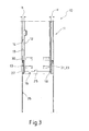
- a telescopic vacuum cleaner suction tube 10 is shown, the inner tube 12 is arranged eccentrically in the outer tube 11.
- the width of the gap 14 is therefore not constant.
- the distance between the inner and outer tubes 12, 11 therefore know in the sectional view of FIG. 3 - with respect to the drawing on the left - the width b and the width c on the right.
- the Inventively formed sealing sleeve 13 find in slightly modified form use.
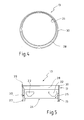
- FIGS. 4 and 5 show a sealing sleeve 13 adapted to the eccentric arrangement of outer and inner tubes 11, 12, FIG. 4 being a plan view of the funnel-shaped second axial end section 17 and FIG. 5 a sectional view of the sealing sleeve 13.
- the sealing sleeve 13 can be adapted in two ways to the eccentric contour of the intermediate space 14 following from the eccentric arrangement of the inner and outer tubes 12, 11.
- the sealing lip 27 and / or 30 is therefore up to the maximum distance b between the inner and outer tubes 12, 11 radially wider and then, adapted to the contour of the gap 14, again narrower. This ensures that the sealing lip 27 and / or 30 rests fully on the inner circumferential surface 26 of the outer tubes over its entire circumference.
- the material thickness of the sleeve wall 20 is adapted to the eccentric contour of the intermediate space 14 in the same way. Also, it is ensured that the sealing lip 27 and / or 30 rests against the inner circumferential surface 26 of the outer tube 11 over its entire circumference.
- the sleeve wall 20 is provided with axially or radially extending externally circumferentially disposed in at least a portion of the sleeve wall 20 spacer ribs.
- the sealing sleeve 13 is supported in the areas on the inner circumferential surface 26 of the outer tube 11, in which the material thickness of the sleeve wall is less than the distance between the outer and inner tubes 11, 12th
Landscapes
- Engineering & Computer Science (AREA)
- Mechanical Engineering (AREA)
- Electric Vacuum Cleaner (AREA)
Abstract
Description
- Die Erfindung betrifft ein teleskopierbares Staubsauger-Saugrohr, mit einem Innenrohr und einem Außenrohr und einer endseitig am inneren Ende des Innenrohres befestigten, im Zwischenraum zwischen Innen- und Außenrohr angeordneten Dichtungshülse aus Kunststoff, deren Hülsenwandung einen ersten, der Innenstirnfläche des Innenrohres zugeordneten, axialen Endabschnitt und einen der Innenstirnfläche des Innenrohres abgewandten, zweiten axialen Endabschnitt aufweist, wobei der Zwischenraum zwischen Innen- und Außenrohr mittels einer von der Dichtungshülse ausgebildeten, sich an einer Innenmantelfläche des Außenrohres abstützenden Dichtlippe abgedichtet ist.
- Derartige Staubsauger-Saugrohre sind beispielsweise in
DE 40 17 721 C2 undEP 0 998 871 B1 beschrieben und zeichnen sich insbesondere dadurch aus, dass zur Abdichtung des Saugrohres der ohnehin vorhandene Spielraum zwischen Außenrohr und Innenrohr genutzt wird. Eine weitere Verengung des Innenrohrquerschnittes und eine daraus folgende Verringerung der Saugleistung wird so vermieden. - Auch wenn sich die Staubsauger-Saugrohre aus dem vorgenannten Stand der Technik in der Praxis in großem Umfang bewährt haben, werden sie weiterhin als verbesserungsfähig angesehen, insbesondere soweit es die Handhabung bei der Montage, eine vereinfachte Produktion der Dichtungshülse und eine weiter verbesserte Abdichtung des Staubsauger-Saugrohres gegen Leckluftströme betrifft.
- Gelöst wird die Aufgabe von einem Staubsauger-Saugrohr mit den Merkmalen des Anspruches 1, insbesondere mit den Merkmalen des Kennzeichenteiles, wonach der zweite axiale Endabschnitt der Hülsenwandung unter Ausbildung einer innenumfänglichen Führungsfläche und unter Ausbildung einer sich an der Innenmantelfläche des Außenrohres abstützenden Dichtlippe trichterförmig erweitert ist. Der besondere Vorteil der erfindungsgemäßen weitergebildeten Dichtungshülse des Staubsauger-Saugrohres besteht darin, dass diese dank ihrer trichterförmig erweiterten Führungsfläche besonders leicht am inneren Ende des Innenrohres angesetzt und aufgeschoben werden kann.
- Gegenüber dem Stand der Technik weist die Dichtungshülse nunmehr im Bereich des zweiten axialen Endabschnittes einen gegenüber dem Außenumfang des Innenrohres leicht größeren Innenumfang auf, womit vermieden wird, dass aufgrund einer leicht ovalen Verformung der Dichtungshülse oder einer nicht ganz exakten Zentrierung von Dichtungshülse zum Innenrohr die Stirnflächen von Innenrohr und Dichtungshülse aufeinander treffen. Beschädigungen der Dichtungshülse werden somit wirksam vermieden.
- Ein wesentlicher Teil der Erfindung ist jedoch auch darin begründet, dass erkannt wurde, dass sich die trichterförmig ausgebildete Führungsfläche durch ein trichterförmiges Aufweiten des zweiten axialen Endabschnittes herstellen lässt, wodurch gleichzeitig die zur Abdichtung des Zwischenraumes zwischen Außen- und Innenrohr notwendige Dichtlippe an der Dichtungshülse ausgeformt ist.
- Bei einer bevorzugten Ausführungsform weist der erste axiale Endabschnitt der Hülsenwandung eine zusätzliche, sich an der Innenmantelfläche des Außenrohres abstützende Dichtlippe auf, so dass der Zwischenraum zwischen Innen- und Außenrohr des Staubsauger-Saugrohres mittels zweier Dichtlippen abgedichtet ist, wodurch sich die im Stand der Technik verbleibenden, geringen Leckluftströme und damit einhergehende Saugleistungsverluste weiter senken lassen.
- Besonders bevorzugt ist es, wenn die zusätzliche Dichtlippe die Innenstirnfläche des Innenrohres axial überragt und sich eigenfedernd an der Innenmantelfläche des Außenrohres abstützt, was sich schon im Stand der Technik als vorteilhaft erwiesen hat.
- Für die korrekte Positionierung der Dichtungshülse auf dem Innenrohr des Staubsauger-Saugrohres ist vorgesehen, dass der erste Endabschnitt der Dichtungshülse innenumfänglich einen an der Innenstirnfläche anliegenden Stützkragen aufweist, welcher den Aufschiebweg der Dichtungshülse auf dem Innenrohr begrenzt und demnach einen Anschlag ausbildet.
- Es vereinfacht die Herstellung eines Staubsauger-Saugrohres erheblich, wenn die Dichtungshülse auf das Innenrohr lediglich aufgerastet wird.
- Bei einem Staubsauger-Saugrohr mit im Außenrohr exzentrisch angeordnetem Innenrohr, wird die Abdichtung des zwischen den Rohren vorhandenen Zwischenraumes mittels einer Dichtlippe gegen Leckluftströmungen abgedichtet, deren Materialstärke der exzentrischen Kontur des Zwischenraumes entspricht. Die Abdichtung kann auch erfolgen, indem die Materialstärke der Hülsenwandung der exzentrischen Kontur des Zwischenraumes angepasst ist.
- Bei einer weiteren Ausführungsform mit einer Dichtungshülse, deren Hülsenwandung eine konstante Stärke aufweist, wird die zentrische Kontur des Zwischenraumes mittels, in zumindest einem Bereich der Hülsenwandung, außenumfänglich an der Hülsenwandung angeordneten Distanzrippen überbrückt, mittels derer sich die Dichtungshülse an der Innenmantelfläche des Außenrohres abstützt. Die Distanzrippen können sowohl axial wie radial ausgerichtet sein.
- Weitere Vorteile der Erfindung ergeben sich aus der folgenden Zeichnungsbeschreibung. Es zeigen:
- Fig. 1
- einen Längsschnitt durch einen axialen Teilbereich eines erfindungsgemäßen Staubsauger-Saugrohres,
- Fig. 2
- eine Dichtungshülse des Staubsauger-Saugrohres,
- Fig. 3
- den Längsschnitt durch einen axialen Teilbereich eines erfindungsgemäßen Staubsauger-Saugrohr mit exzentrisch im Außenrohr angeordneten Innenrohr,
- Fig. 4
- eine Aufsicht auf eine Dichtungshülse mit exzentrischer Kontur, und
- Fig. 5
- eine Schnittdarstellung einer Dichtungshülse mit exzentrischer Kontur.
- In den Figuren ist ein Staubsauger-Saugrohr insgesamt mit der Bezugsziffer 10 versehen.
- Das Staubsauger-Saugrohr 10 umfasst ein Außenrohr 11, ein Innenrohr 12 sowie eine Dichtungshülse 13 und bildet so eine teleskopierbare Staubsauger-Saugrohranordnung aus. Zwischen Außenrohr 11 und Innenrohr 12 befindet sich ein Zwischenraum 14, welcher das notwendige Passungsspiel zwischen Außen- und Innenrohr 11, 12 gewährleistet.
- Um Saugleistungsverluste durch Leckluftströme entlang des Zwischenraumes 14 zu vermeiden, ist die Dichtungshülse 13 außenumfänglich auf dem Innenrohr 12 angeordnet, wobei die Dichtungshülse 13 aus einem für Dichtungszwecke geeigneten, hinreichend rückstellelastischen thermoplastischen Kunststoff, wie z.B. aus Polyamid, aus Polyäthylen oder aus Polypropylen besteht.
- Die Dichtungshülse 13 weist einen ersten axialen Endabschnitt 15 auf, welcher dem inneren Ende 16 des Innenrohres 12 zugeordnet ist. Ein zweiter axialer Endabschnitt 17 ist dem inneren Ende 16 des Innenrohres 12 bzw. dessen Innenstirnfläche 18 abgewandt und folglich im Bereich der äußeren Mantelfläche 19 des Innenrohres 12 angeordnet.
- Die den ersten und zweiten axialen Endabschnitt 15, 17 bildende Hülsenwandung 20 liegt mit ihrer Innenumfangsfläche 21 straff an der äußeren Mantelfläche 19 des Innenrohres 12 an und weist umfangsverteilt Rastausnehmungen 22 auf, welche von korrespondierenden Rastmitteln 23 des Innenrohres durchgriffen werden und die Dichtungshülse 13 fest auf dem Innenrohr 12 anordnen.
- Die Rastmittel 23 sind im vorliegenden Ausführungsbeispiel von in Richtung Außenrohr 11 weisenden Ausprägungen 31 des Innenrohres 12 gebildet.
- Im Bereich des ersten axialen Endabschnittes 15 weist die Dichtungshülse innenumfänglich einen Kragen 24 auf, dessen Anschlagfläche 25 bei montierter Dichtungshülse 13 an der Stirnfläche 18 des Innenrohres 12 anliegt und somit den Aufschubweg der Dichtungshülse 13 auf dem Innenrohr 12 begrenzt.
- Der das innere Ende 16 des Innenrohres 12 axial überragende erste axiale Endabschnitt 15 der Dichtungshülse 13 bildet des weiteren eine sich an der inneren Mantelfläche 26 des Außenrohres 11 eigenfedernd abstützende, erste Dichtlippe 27 aus, welche den Zwischenraum 14 zwischen Innenrohr 12 und Außenrohr 11 gegen Leckluftströmungen verschließt.
- Um das Aufschieben der Dichtungshülse 13 auf das Innenrohr 12 wesentlich zu vereinfachen, ist der zweite Endabschnitt 16 der Hülsenwandung 20 trichterförmig erweitert. Hierdurch wird zunächst eine ebenfalls trichterförmige, schräg in Richtung des inneren Endes 16 des Innenrohres 12 zulaufende Führungsfläche 28 gebildet. Anders ausgedrückt, weist die Dichtungshülse 13 im Bereich des zweiten axialen Endabschnittes 17 einen bezüglich des Außenumfanges des Innenrohres 12 erweiterten Innenumfang auf.
- Dies hat zunächst den Vorteil, dass die Dichtungshülse 13 auch bezüglich des Innenrohres 12 leicht radial dezentriert an das innenseitige Ende 16 des Innenrohres 12 angesetzt werden kann, ohne dass die Stirnfläche 18 des Innenrohres 12 auf die Stirnfläche 29 im Bereich des zweiten axialen Endabschnittes 17 der Dichtungshülse 13 trifft und so die Dichtungshülse 13 vorgeschädigt wird.
- Beim Aufschieben der Dichtungshülse 13 auf das Innenrohr 12 gleitet dessen Stirnfläche 18 auf der Führungsfläche 28 entlang und weitet die Dichtungshülse 13 kontinuierlich auf, so dass diese schließlich stramm an der äußeren Mantelfläche 19 des Innenrohres 12 mit ihrer Innenumfangsfläche 21 anliegt, was bezüglich der Handhabung bei der Montage des Staubsauger-Saugrohres 10 ein weiterer Vorteil ist.
- Zusätzlich wird durch die trichterförmige Erweiterung der Hülsenwandung 20 im zweiten axialen Endabschnitt 17 eine zweite sich an der inneren Mantelfläche 26 des Außenrohres 11 eigenfedernd abstützende Dichtlippe 30 geschaffen, so dass Leckluftströmungen entlang des Zwischenraumes 14 durch die doppelte Abdichtung auf ein Minimum reduziert werden.
- Alternativ kann die Herstellung der Dichtungshülse 13 wesentlich vereinfacht werden, wenn auf die erste Dichtlippe 27 im ersten axialen Endabschnitt 15 verzichtet wird, ohne dass Saugleistungsverluste gegenüber dem Stand der Technik zu befürchten wären.
- In Fig. 3 ist ein teleskopierbares Staubsauger-Saugrohr 10 dargestellt, dessen Innenrohr 12 exzentrisch im Außenrohr 11 angeordnet ist. Die Breite des Zwischenraumes 14 ist daher nicht konstant. Der Abstand zwischen Innen- und Außenrohr 12, 11 weißt in der Schnittdarstellung der Fig. 3 daher - bezüglich der Zeichnung links - die Breite b und rechts die Breite c auf. Auch bei einer exzentrischen Anordnung von Innen- und Außenrohr 12,11 kann die erfindungsgemäß ausgebildete Dichtungshülse 13 in leicht modifizierter Form Verwendung finden.
- Die Fig. 4 und 5 zeigen eine an die exzentrische Anordnung von Außen- und Innenrohr 11, 12 angepassten Dichtungshülse 13, wobei Fig. 4 eine Aufsicht auf den trichterförmig erweiterten zweiten axialen Endabschnitt 17 und Fig. 5 eine Schnittdarstellung der Dichtungshülse 13 ist.
- Die Dichtungshülse 13 kann auf zweierlei Art an die aus der exzentrischen Anordnung von Innen- und Außenrohr 12, 11 folgende exzentrische Kontur des Zwischenraumes 14 angepasst werden. Zum einen ist es möglich, die Materialstärke der Dichtlippe 27 und/oder 30 an die Kontur des Zwischenraumes anzupassen. Die Dichtlippe 27 und/oder 30 wird demzufolge bis zum maximalen Abstand b zwischen Innen- und Außenrohr 12, 11 radial breiter und anschließend, der Kontur des Zwischenraumes 14 angepasst, wieder schmaler. So ist sichergestellt das die Dichtlippe 27 und/oder 30 über ihren gesamten Umfang satt an der Innenmantelfläche 26 des Außenrohre anliegt.
- Bei einer anderen Ausführungsform, wie sie in Fig. 5 dargestellt ist, wird in gleicher Weise die Materialstärke der Hülsenwandung 20 an die exzentrische Kontur des Zwischenraumes 14 angepasst. Auch so ist sicher gestellt, dass die Dichtlippe 27 und/oder 30 über ihren gesamten Umfang an der Innenmantelfläche 26 des Außenrohres 11 anliegt.
- Bei einer dritten, nicht dargestellten Ausführungsform ist die Hülsenwandung 20 mit axial oder radial verlaufenden, außenumfänglich in zumindest einem Teilbereich der Hülsenwandung 20 angeordneten Distanzrippen versehen. Mittels dieser Distanzrippen stützt sich die Dichtungshülse 13 in den Bereichen an der Innenmantelfläche 26 des Außenrohres 11 ab, in denen die Materialstärke der Hülsenwandung geringer ist als der Abstand zwischen Außen- und Innenrohr 11, 12.
Claims (8)
- Teleskopierbares Staubsauger-Saugrohr (16), mit einem Innenrohr (12) und einem Außenrohr (11) und einer endseitig am inneren Ende (16) des Innenrohres (12) befestigten, im Zwischenraum (14) zwischen Innen- und Außenrohr (12, 11) angeordneten Dichtungshülse (13) aus Kunststoff, deren Hülsenwandung (20) einen ersten, der Innenstirnfläche (18) des Innenrohres (12) zugeordneten, axialen Endabschnitt (15) und einen der Stirnfläche (18) des Innenrohres (12) abgewandten, zweiten axialen Endabschnitt (17) aufweist, wobei der Zwischenraum (14) zwischen Innen- und Außenrohr (12, 11) mittels einer von der Dichtungshülse (13) ausgebildeten, sich an einer Innenmantelfläche (26) des Außenrohres (11) abstützenden Dichtlippe (27, 30) abgedichtet ist, dadurch gekennzeichnet, dass der zweite axiale Endabschnitt (17) der Hülsenwandung (20) unter Ausbildung einer innenumfänglichen Führungsfläche (28) und unter Ausbildung einer sich an der Innenmantelfläche (26) des Außenrohres (11) abstützenden Dichtlippe (30) trichterförmig erweitert ist.
- Teleskopierbares Staubsauger-Saugrohr nach Anspruch 1, dadurch gekennzeichnet, dass der erste axiale Endabschnitt (15) der Hülsenwandung (20) eine zusätzliche, sich an der Innenmantelfläche (26) des Außenrohres (11) abstützende Dichtlippe (27) ausbildet.
- Teleskopierbares Staubsauger-Saugrohr nach Anspruch 2, dadurch gekennzeichnet, dass die Dichtlippe (27) die Innenstirnfläche (18) des Innenrohres (12) axial überragend und sich eigenfedernd an der Innenmantelfläche (26) des Außenrohres (11) abstützend ausgebildet ist.
- Teleskopierbares Staubsauger-Saugrohr nach einem der Ansprüche 1 bis 3, dadurch gekennzeichnet, dass der axiale erste Endabschnitt (15) der Dichtungshülse (13) innenumfänglich einen an der Innenstirnfläche (18) anliegenden Stützkragen (24) aufweist.
- Teleskopierbares Staubsauger-Saugrohr nach einem der Ansprüche 1 bis 4, dadurch gekennzeichnet, dass die Dichtungshülse (13) auf das Innenrohr (12) aufgerastet ist.
- Teleskopierbares Staubsauger-Saugrohr nach einem der vorhergehenden Ansprüche, dadurch gekennzeichnet, dass bei einem im Außenrohr (11) exzentrisch angeordneten Innenrohr (12) die Materialstärke der Dichtlippe (27, 30) im wesentlichen der exzentrisch verlaufenden Kontur des Zwischenraumes (14) entspricht.
- Teleskopierbares Staubsauger-Saugrohr nach einem der vorhergehenden Ansprüche, dadurch gekennzeichnet, dass bei einem im Außenrohr (11) exzentrisch angeordnetem Innenrohr (12) die Materialstärke der Hülsenwandung (20) im wesentlichen der exzentrisch verlaufenden Kontur des Zwischenraumes (14) entspricht.
- Teleskopierbares Staubsauger-Saugrohr nach einem der Ansprüche 1 bis 6, dadurch gekennzeichnet, dass bei einem im Außenrohr (11) exzentrisch angeordneten Innenrohr (12) die Hülsenwandung (20) zumindest in einem Teilbereich außenumfänglich angeordnete Distanzrippen aufweist, mittels derer die Dichtungshülse (13) an der Innenmantelfläche (26) des Außenrohres (11) abgestützt ist.
Priority Applications (1)
| Application Number | Priority Date | Filing Date | Title |
|---|---|---|---|
| PL07012128T PL1872702T3 (pl) | 2006-06-29 | 2007-06-21 | Teleskopowa rura ssąca do odkurzacza |
Applications Claiming Priority (1)
| Application Number | Priority Date | Filing Date | Title |
|---|---|---|---|
| DE102006030138A DE102006030138B3 (de) | 2006-06-29 | 2006-06-29 | Teleskopierbares Staubsauger-Saugrohr |
Publications (3)
| Publication Number | Publication Date |
|---|---|
| EP1872702A2 true EP1872702A2 (de) | 2008-01-02 |
| EP1872702A3 EP1872702A3 (de) | 2008-08-13 |
| EP1872702B1 EP1872702B1 (de) | 2010-05-19 |
Family
ID=38441941
Family Applications (1)
| Application Number | Title | Priority Date | Filing Date |
|---|---|---|---|
| EP07012128A Ceased EP1872702B1 (de) | 2006-06-29 | 2007-06-21 | Teleskopierbares Staubsauger-Saugrohr |
Country Status (5)
| Country | Link |
|---|---|
| EP (1) | EP1872702B1 (de) |
| KR (1) | KR101293932B1 (de) |
| CN (1) | CN101095605B (de) |
| DE (2) | DE102006030138B3 (de) |
| PL (1) | PL1872702T3 (de) |
Cited By (2)
| Publication number | Priority date | Publication date | Assignee | Title |
|---|---|---|---|---|
| EP2277427A2 (de) | 2009-07-24 | 2011-01-26 | Samsung Gwangju Electronics Co., Ltd. | Teleskoprohr für elektronische Vorrichtung |
| WO2013064050A1 (zh) * | 2011-11-02 | 2013-05-10 | 江苏国新金属制品有限公司 | 真空吸尘器伸缩管 |
Families Citing this family (4)
| Publication number | Priority date | Publication date | Assignee | Title |
|---|---|---|---|---|
| CN102652653B (zh) * | 2012-05-09 | 2014-10-08 | 江苏国新金属制品有限公司 | 真空吸尘器伸缩管 |
| EP2614761B1 (de) | 2012-01-10 | 2016-04-13 | Fischer Rohrtechnik GmbH | Dichtsystem für ein Staubsauger-Saugrohr |
| CN107184152A (zh) * | 2017-07-18 | 2017-09-22 | 苏州市欧陆杰电器有限公司 | 吸尘器的伸缩管结构 |
| CN109821307B (zh) * | 2019-03-28 | 2021-01-12 | 安徽春博环保科技有限公司 | 一种工业除尘器 |
Family Cites Families (10)
| Publication number | Priority date | Publication date | Assignee | Title |
|---|---|---|---|---|
| US3656771A (en) * | 1970-12-11 | 1972-04-18 | Irrigation Accessories Co | Flexible seal assembly for spigot and bell conduit joint |
| FR2139688B1 (de) * | 1971-05-28 | 1973-05-25 | Pont A Mousson Fond | |
| DE4017721A1 (de) * | 1990-06-01 | 1991-12-05 | Froh Roehren | Teleskopierbares staubsauger-saugrohr |
| DE19850355A1 (de) * | 1998-11-02 | 2000-05-11 | Froh Carl Gmbh | Teleskopierbares Staubsauger-Saugrohr |
| CN2381258Y (zh) * | 1999-07-23 | 2000-06-07 | 邬兴堂 | 吸尘器伸缩吸管的密封衬套 |
| CN2385668Y (zh) * | 1999-08-25 | 2000-07-05 | 倪祖根 | 吸尘器的偏心伸缩吸管 |
| CN2398962Y (zh) * | 1999-11-10 | 2000-10-04 | 顾建芳 | 吸尘器的无级伸缩吸尘管 |
| US6530118B2 (en) * | 2000-11-06 | 2003-03-11 | Samsung Kwangju Electronics Co., Ltd. | Sub-suction pipe assembly for vacuum cleaner |
| DE10142684C1 (de) * | 2001-08-31 | 2002-11-07 | Fischer Rohrtechnik Gmbh | Staubsauger-Saugrohr mit einem auf dem Innenrohr angeordneten Dichtring mit Nut zur Aufnahme eines O-Ringes |
| DE102005059107B3 (de) * | 2005-12-08 | 2007-03-01 | Fon Telescopic Systems Gmbh | Teleskopierbares Staubsauger-Saugrohr |
-
2006
- 2006-06-29 DE DE102006030138A patent/DE102006030138B3/de not_active Withdrawn - After Issue
-
2007
- 2007-06-21 DE DE502007003824T patent/DE502007003824D1/de active Active
- 2007-06-21 EP EP07012128A patent/EP1872702B1/de not_active Ceased
- 2007-06-21 PL PL07012128T patent/PL1872702T3/pl unknown
- 2007-06-29 CN CN200710112274XA patent/CN101095605B/zh not_active Expired - Fee Related
- 2007-06-29 KR KR1020070065096A patent/KR101293932B1/ko not_active Expired - Fee Related
Cited By (3)
| Publication number | Priority date | Publication date | Assignee | Title |
|---|---|---|---|---|
| EP2277427A2 (de) | 2009-07-24 | 2011-01-26 | Samsung Gwangju Electronics Co., Ltd. | Teleskoprohr für elektronische Vorrichtung |
| EP2277427A3 (de) * | 2009-07-24 | 2011-04-06 | Samsung Gwangju Electronics Co., Ltd. | Teleskoprohr für elektronische Vorrichtung |
| WO2013064050A1 (zh) * | 2011-11-02 | 2013-05-10 | 江苏国新金属制品有限公司 | 真空吸尘器伸缩管 |
Also Published As
| Publication number | Publication date |
|---|---|
| EP1872702A3 (de) | 2008-08-13 |
| PL1872702T3 (pl) | 2010-10-29 |
| KR20080001666A (ko) | 2008-01-03 |
| KR101293932B1 (ko) | 2013-08-08 |
| DE102006030138B3 (de) | 2007-10-18 |
| CN101095605A (zh) | 2008-01-02 |
| DE502007003824D1 (de) | 2010-07-01 |
| CN101095605B (zh) | 2011-04-13 |
| EP1872702B1 (de) | 2010-05-19 |
Similar Documents
| Publication | Publication Date | Title |
|---|---|---|
| AT401417B (de) | Schiebehülsen-verbindung für kunststoffrohre | |
| EP1872702B1 (de) | Teleskopierbares Staubsauger-Saugrohr | |
| EP3173675B1 (de) | Schlauchanschluss | |
| EP2330326B1 (de) | Rohrförmiges Bauteil | |
| DE19547982A1 (de) | Stoßverbindung von Luftkanalabschnitten | |
| WO2008086765A2 (de) | Taschensegmentkäfig für ein wälzkörperlager und wälzkörperlager mit dem taschensegmentkäfig | |
| EP1351004A1 (de) | Stossverbindung zwischen zwei Rohrabschnitten aus Blech und Verfahren zu deren Herstellung | |
| DE20012676U1 (de) | Verbindung eines Lagerringes mit einem Trägerteil | |
| EP3803180B1 (de) | Anschlussvorrichtung für eine schlauchanordnung | |
| EP2725957A1 (de) | Verbindungshülse zur verbindung von rohren mit weiteren bauteilen | |
| DE202006010149U1 (de) | Teleskopierbares Staubsauger-Saugrohr | |
| DE102023107561A1 (de) | Rohrverbinder mit Halteeinrichtung | |
| DE202009014250U1 (de) | Steckkupplung zum Verbinden von insbesondere Kunststoff-Rohren | |
| DE3420523A1 (de) | Radialwellendichtring | |
| DE3111726C1 (de) | Dichtungsring | |
| DE102007017157B4 (de) | Dichtmuffe für einen Rohrverbinder | |
| DE102007008965B4 (de) | Kolben für eine Fahrzeug-Luftfeder und Anschlussstecker zum Einstecken in eine Aufnahmeöffnung des Kolbens | |
| EP1531242A2 (de) | Entkoppelelement für Abgasanlagen | |
| DE2902960A1 (de) | Rohr-kompensator | |
| EP2982893B1 (de) | Rohrklemmanordnung | |
| EP1599690B1 (de) | Rohrkupplung mit gummielastischer dichtmanschette | |
| DE202022102316U1 (de) | Hochdichte Rohrverbindung, und Dichtungselement | |
| EP4151896A1 (de) | Rohrverbindung, und dichtung | |
| EP3401584A1 (de) | Rohr, insbesondere abgasführungsrohr | |
| DE202023101380U1 (de) | Rohrverbinder mit Haltevorrichtung |
Legal Events
| Date | Code | Title | Description |
|---|---|---|---|
| PUAI | Public reference made under article 153(3) epc to a published international application that has entered the european phase |
Free format text: ORIGINAL CODE: 0009012 |
|
| AK | Designated contracting states |
Kind code of ref document: A2 Designated state(s): AT BE BG CH CY CZ DE DK EE ES FI FR GB GR HU IE IS IT LI LT LU LV MC MT NL PL PT RO SE SI SK TR |
|
| AX | Request for extension of the european patent |
Extension state: AL BA HR MK YU |
|
| PUAL | Search report despatched |
Free format text: ORIGINAL CODE: 0009013 |
|
| AK | Designated contracting states |
Kind code of ref document: A3 Designated state(s): AT BE BG CH CY CZ DE DK EE ES FI FR GB GR HU IE IS IT LI LT LU LV MC MT NL PL PT RO SE SI SK TR |
|
| AX | Request for extension of the european patent |
Extension state: AL BA HR MK RS |
|
| 17P | Request for examination filed |
Effective date: 20090129 |
|
| AKX | Designation fees paid |
Designated state(s): DE HU PL |
|
| GRAP | Despatch of communication of intention to grant a patent |
Free format text: ORIGINAL CODE: EPIDOSNIGR1 |
|
| GRAS | Grant fee paid |
Free format text: ORIGINAL CODE: EPIDOSNIGR3 |
|
| GRAA | (expected) grant |
Free format text: ORIGINAL CODE: 0009210 |
|
| AK | Designated contracting states |
Kind code of ref document: B1 Designated state(s): DE HU PL |
|
| REF | Corresponds to: |
Ref document number: 502007003824 Country of ref document: DE Date of ref document: 20100701 Kind code of ref document: P |
|
| REG | Reference to a national code |
Ref country code: PL Ref legal event code: T3 |
|
| PLBE | No opposition filed within time limit |
Free format text: ORIGINAL CODE: 0009261 |
|
| STAA | Information on the status of an ep patent application or granted ep patent |
Free format text: STATUS: NO OPPOSITION FILED WITHIN TIME LIMIT |
|
| REG | Reference to a national code |
Ref country code: HU Ref legal event code: AG4A Ref document number: E009275 Country of ref document: HU |
|
| 26N | No opposition filed |
Effective date: 20110222 |
|
| REG | Reference to a national code |
Ref country code: DE Ref legal event code: R097 Ref document number: 502007003824 Country of ref document: DE Effective date: 20110221 |
|
| REG | Reference to a national code |
Ref country code: DE Ref legal event code: R082 Ref document number: 502007003824 Country of ref document: DE Representative=s name: PATENTANWAELTE OSTRIGA, SONNET, WIRTHS & VORWE, DE |
|
| PGFP | Annual fee paid to national office [announced via postgrant information from national office to epo] |
Ref country code: PL Payment date: 20170613 Year of fee payment: 11 |
|
| PGFP | Annual fee paid to national office [announced via postgrant information from national office to epo] |
Ref country code: HU Payment date: 20170620 Year of fee payment: 11 |
|
| PG25 | Lapsed in a contracting state [announced via postgrant information from national office to epo] |
Ref country code: HU Free format text: LAPSE BECAUSE OF NON-PAYMENT OF DUE FEES Effective date: 20180622 |
|
| PGFP | Annual fee paid to national office [announced via postgrant information from national office to epo] |
Ref country code: DE Payment date: 20190625 Year of fee payment: 13 |
|
| PG25 | Lapsed in a contracting state [announced via postgrant information from national office to epo] |
Ref country code: PL Free format text: LAPSE BECAUSE OF NON-PAYMENT OF DUE FEES Effective date: 20180621 |
|
| REG | Reference to a national code |
Ref country code: DE Ref legal event code: R119 Ref document number: 502007003824 Country of ref document: DE |
|
| PG25 | Lapsed in a contracting state [announced via postgrant information from national office to epo] |
Ref country code: DE Free format text: LAPSE BECAUSE OF NON-PAYMENT OF DUE FEES Effective date: 20210101 |