EP1980780B1 - Dichtmuffe für einen Rohrverbinder - Google Patents
Dichtmuffe für einen Rohrverbinder Download PDFInfo
- Publication number
- EP1980780B1 EP1980780B1 EP20080002992 EP08002992A EP1980780B1 EP 1980780 B1 EP1980780 B1 EP 1980780B1 EP 20080002992 EP20080002992 EP 20080002992 EP 08002992 A EP08002992 A EP 08002992A EP 1980780 B1 EP1980780 B1 EP 1980780B1
- Authority
- EP
- European Patent Office
- Prior art keywords
- sealing
- sealing sleeve
- sleeve according
- support region
- support zone
- Prior art date
- Legal status (The legal status is an assumption and is not a legal conclusion. Google has not performed a legal analysis and makes no representation as to the accuracy of the status listed.)
- Not-in-force
Links
Images
Classifications
-
- F—MECHANICAL ENGINEERING; LIGHTING; HEATING; WEAPONS; BLASTING
- F16—ENGINEERING ELEMENTS AND UNITS; GENERAL MEASURES FOR PRODUCING AND MAINTAINING EFFECTIVE FUNCTIONING OF MACHINES OR INSTALLATIONS; THERMAL INSULATION IN GENERAL
- F16L—PIPES; JOINTS OR FITTINGS FOR PIPES; SUPPORTS FOR PIPES, CABLES OR PROTECTIVE TUBING; MEANS FOR THERMAL INSULATION IN GENERAL
- F16L21/00—Joints with sleeve or socket
- F16L21/002—Sleeves or nipples for pipes of the same diameter; Reduction pieces
- F16L21/005—Sleeves or nipples for pipes of the same diameter; Reduction pieces made of elastic material, e.g. partly or completely surrounded by clamping devices
Definitions
- the invention relates to a sealing sleeve for a pipe connector with a circumferential body according to claim 1,
- DE 26 03 393 A1 discloses a method of manufacturing a plastic pipe connector, wherein the pipe connector comprises a preformed annular body into which a second annular member is injected.
- the second component covers the radial inner side of the main part except for the area of an annular stop rib.
- the main part is here made of a relatively stiff material such as polyvinyl chloride or polypropylene, while the second component can be made of a softened polyvinyl chloride.
- the first main part thus forms a support zone, while the second component forms two sealing zones. In this case, the second component is covered by the first main part, that is supported over the entire axial extent.
- a socket joint for plastic pipes wherein a sleeve has a support zone which surrounds two sealing zones radially. Between the two sealing zones, a spacer body is provided, which defines the axial distance between the sealing zones and to prevent tilting of plastic pipes within the socket joint. This sleeve connection is thus formed from the support zone, two sealing zones and a spacer.
- DE 297 18 867 U1 discloses a pipe coupling having a support zone with two support arms, wherein two sealing zones are provided. Also in this pipe coupling, the sealing zones are covered axially by the support zone.
- Another sealing sleeve is used for example in a pipe connector, which is offered under the name "NORMACONNECT Rapid” by Rasmussen GmbH, Maintal, Germany.
- a pipe connector In the frontal connection of pipes, a pipe connector is used, in each of which the end of a pipe is inserted from both end faces. In this case, the sealing lip lies against the circumference of the respective Pipe end on. Then, when the pipe connector is stretched, the sealing lip on the circumference of the respective Pipe ends pressed and thus seals the connection between the two tubes.
- the connector may have a clamp-like jacket, in which the sealing sleeve is inserted.
- such a pipe connector has a certain weight.
- the invention has for its object to save weight.
- sealing zones are arranged at axial ends of the support zone, a transition between the support zone and at least one sealing zone at an angle of ⁇ 90 ° to the peripheral wall, from which the transition proceeds, and the projection has a recess.
- the sealing zones must be able to reliably seal the inserted pipe ends.
- the sealing zones must have a certain elasticity or flexibility.
- the support zone does not have to be elastic or not elastic to the degree. Their main function is basically to connect the two sealing zones and hold them in place. For the support zone you can therefore use a material, which is less elastic, but it is lighter. This way you can weight at the Save sealing sleeve. Since a transition between the support zone and at least one sealing zone at an angle ⁇ 90 ° to the peripheral wall, from which the transition proceeds, one can on the one hand keep the material thickness in the radial direction relatively small.
- connection length between the support zone and the sealing zone becomes sufficiently long. For example, if the transition is at an angle of 45, then you have a 40% longer connection distance between the support zone and the sealing zone, which has a favorable effect on the load capacity of the sealing sleeve.
- the first material and the second material are each formed as plastic. You can then select the two plastics on their tasks, so that, for example, the sealing zones elastic enough and the support zone can form strong enough.
- the first material is a polypropylene and the second material is a thermoplastic elastomer.
- Polypropylene has the advantage of a low weight. From a waste disposal point of view, polypropylene is also cheaper than the previously widely used EPDM. It may be formed, for example, photochemically degradable, so that the disposal is beneficial.
- the proportion of the second material to the mass of the sealing sleeve can be kept small, so that one has to take less consideration for the weight, but can choose the second material, especially with regard to the function of the seal.
- Thermoplastic elastomers have the advantage that on the one hand the performance characteristics of elastomers and on the other hand possess the processing properties of thermoplastics.
- the second material is formed as a thermoplastic vulcanizate (TPV).
- TPV thermoplastic vulcanizate
- a thermoplastic vulcanizate has similar functional performances and properties as conventional vulcanized rubber products, but can be processed with the speed, efficiency and economy of thermoplastics. They are also easier to dispose of than conventional vulcanized rubbers.
- the body is formed as a 2-component injection molded part. This facilitates the production. You can form the support zone and the two sealing zones simultaneously or successively in an injection mold.
- the support zone in at least one section has a radial thickness which is at most 60% of the lowest radial thickness of the sealing zones. So you can dimension the support zone so relatively weak, because it has basically only the task of positioning the two sealing zones relative to each other and to hold in this position.
- the use of a radially thin support zone saves material and thus weight.
- the support zone has a thickening at its axial end adjacent to a sealing zone.
- the thickening on the one hand creates a sufficiently long transition between the support zone and the sealing zone, so that the sealing zone can be held with sufficient strength at the support zone.
- Anmuß the support zone otherwise not be made very thick, but they can be kept relatively thin.
- the thickening is otherwise formed integrally with a connection region of the support zone, so that here is given sufficient strength.
- the support zone has a central, radially inwardly directed projection having two parallel axial end faces which continue at their radially outer ends in diverging surfaces.
- the projection is used to separate the two tubes to be connected to the tube connector.
- the tubes abut with their end faces on the parallel axial end faces of the projection.
- the diverging surfaces ensure that the transition between the projection and the rest of the support zone has sufficient stability, even if the support zone has otherwise only a relatively small material thickness.
- each surface is at an angle in the range of 30 ° to 60 ° to its front side. This ensures sufficient thickening in the region of the transition from the projection to the rest of the support zone.
- the surface has a radial extent of not more than 75% of the radial extent of the end face. This ensures that the projection has a sufficient investment length for the end faces of the pipes to be joined. On the other hand extends the transition between the projection and the rest of the support zone over a relatively short radial length, so that is not wasted space unnecessarily.
- the projection has a recess which extends from its radial outer side.
- This recess has two advantages. On the one hand material is saved, which in turn leads to a weight saving. On the other hand, the elasticity of the support zone is increased in the region in which the two pipe ends collide, so to speak. The sealing sleeve is thus more resilient.
- the recess is formed circumferentially. This results in the same proportions in all circumferential directions.
- the recess merges with a curved transition section in the radial outer side of the support zone. This keeps loads from edges or tips small.
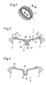
- a sealing sleeve 1 for a pipe connector has an in Fig. 2 shown in cross-section body 2, which is formed circumferentially.
- the body 2 has at its axial ends in each case a sealing lip 3, 4, which extend radially inwardly.
- the sealing lips 3, 4 are in the assembled state on the peripheral surface of two pipe ends, which are bridged by the sealing sleeve 1. By a clamp not shown, the sealing lips 3, 4 are additionally pressed on the circumference of the pipe ends.
- the body 2 has a support zone 5, which is formed from a first material made of plastic.
- the support zone 5 is in Fig. 2 shown crosshatched.
- a plastic for example, polypropylene (PP) can be used, which has a comparatively low weight.
- each have a sealing zone 6, 7 is arranged, each carrying the sealing lip 3, 4.
- the sealing zones 6, 7 are formed from a second material, which is likewise a plastic, namely preferably a thermoplastic elastomer (TPE) and particularly preferably a thermoplastic vulcanizate (TPV).
- TPE thermoplastic elastomer
- TPV thermoplastic vulcanizate
- the support zone 5 and the two sealing zones 6, 7 abut one another in each case in a transition 8, 9 and are connected to one another there.
- the transitions 8, 9 are at an angle of about 45 ° to the radial outside 10 of the body 2. This increases the effective length of the transitions 8, 9 by about 40% compared to a length that would result if the transitions 8, 9 were at right angles to Outside 10 would run.
- the body 2 is formed as a 2K element, ie as a 2-component component, wherein the two components can be injected together or in succession in the same form.
- a 2K element ie as a 2-component component
- the body 2 in the region of the transitions 8, 9 has a thickness D.
- the support zone 5 has on two support arms 11, 12 each have a much smaller thickness d, wherein this radial thickness of the support zone 5 is at most 60% of the lowest radial thickness D of the sealing zone 6, 7.
- the thickness d of the support zone 5 may be on the order of about 1 mm.
- the support arms 11, 12 at their axial ends in each case a thickening 13, 14.
- the support zone 5 has a radially inwardly directed projection 15 which has two substantially parallel axial end faces 16, 17.
- the two end faces 16, 17 of the projection 15 serve as a stop for the pipe ends, which are inserted into the sealing sleeve 1.
- the projection 15 extends radially inward than the sealing lips 3, 4.
- the end faces 16, 17 pass over into surfaces 18, 19, which diverge, ie, move away from one another in the axial direction.
- the angle at which the surfaces 18, 19 are to the end faces 16, 17, is in the range of 30 ° to 60 °, preferably at about 45 °.
- the surfaces 18, 19 have an extent in the radial direction, which is at most 75% of the radial extent of the end faces 16, 17. So you do not use too much space on the reinforcement of the support zone at the transition between the projection 15 and the support arms 11, 12th
- the support arms 11, 12 are inclined slightly outwards relative to the axial direction, for example in the range of 5 to 20 °. As a result, the support zone 5 yield elastically to a small extent in the axial direction.
- Fig. 3 shows a modified embodiment of the invention, which is largely the of Fig. 2 equivalent. The same elements are therefore provided with the same reference numerals.
- the projection 15 in the embodiment according to Fig. 3 has a central recess 20 which is formed circumferentially continuous in the circumferential direction.
- the recess 20 goes over curved transition portions 21 in the outside 10 via. Through the recess 20 can form the transition section 5 with a further reduced mass, so that the sealing sleeve 1 can build easier.
- the recess 20 has the advantage that the sealing sleeve 1 in the region where the two pipe ends to be sealed, can easily deform elastically, so that the sealing sleeve 1 is able to absorb loads that occur in the axial direction.
Landscapes
- Engineering & Computer Science (AREA)
- General Engineering & Computer Science (AREA)
- Mechanical Engineering (AREA)
- Joints With Sleeves (AREA)
Description
- Die Erfindung betrifft eine Dichtmuffe für einen Rohrverbinder mit einem umlaufenden Korpus gemäß Anspruch 1.,
- In
DE 26 03 393 A1 ist ein Verfahren zum Herstellen eines Kunststoffrohrverbinders offenbart, wobei der Rohrverbinder ein vorgeformtes ringförmiges Hauptteil aufweist, in das ein zweites ringförmiges Bauteil eingespritzt wird. Das zweite Bauteil bedeckt dabei bis auf den Bereich einer ringförmigen Anschlagrippe die radiale Innenseite des Hauptteils. Das Hauptteil ist dabei aus einem relativ steifen Material wie beispielsweise Polyvinylchlorid oder Polypropylen hergestellt, während das zweite Bauteil aus einem weich gestellten Polyvinylchlorid hergestellt werden kann. Das erste Hauptteil bildet also eine Tragzone, während das zweite Bauteil zwei Dichtzonen bildet. Dabei wird das zweite Bauteil durch das erste Hauptteil abgedeckt, also über die gesamte axiale Erstreckung gestützt. - Aus
DE 11 60 248 B ist eine Muffenverbindung für Kunststoffrohre bekannt, wobei eine Muffe eine Tragzone aufweist, die zwei Dichtzonen radial umgibt. Zwischen den zwei Dichtzonen ist ein Distanzkörper vorgesehen, der den axialen Abstand zwischen den Dichtzonen festlegt und ein Verkanten von Kunststoffrohren innerhalb der Muffenverbindung verhindern soll. Diese Muffenverbindung wird also aus der Tragzone, zwei Dichtzonen und einem Distanzkörper gebildet. -
DE 297 18 867 U1 offenbart eine Rohrkupplung, die eine Tragzone mit zwei Tragarmen aufweist, wobei zwei Dichtzonen vorgesehen sind. Auch bei dieser Rohrkupplung werden die Dichtzonen axial von der Tragzone überdeckt. - Eine weitere Dichtmuffe wird beispielsweise in einem Rohrverbinder verwendet, der unter der Bezeichnung "NORMACONNECT Rapid" von der Rasmussen GmbH, Maintal, Deutschland, angeboten wird.
- Bei der stirnseitigen Verbindung von Rohren wird ein Rohrverbinder verwendet, in den von beiden Stirnseiten her jeweils das Ende eines Rohres eingeschoben wird. Dabei legt sich die Dichtlippe an den Umfang des jeweiligen Rohrendes an. Wenn dann der Rohrverbinder gespannt wird, wird die Dichtlippe auf den Umfang der jeweiligen Rohrenden gepresst und dichtet somit die Verbindung zwischen den beiden Rohren ab. Um diese Spannkraft aufzubringen, kann der Verbinder einen schellenartigen Mantel aufweisen, in den die Dichtmuffe eingelegt ist.
- Insbesondere bei grösseren Nenndurchmessern weist ein derartiger Rohrverbinder ein gewisses Gewicht auf.
- Der Erfindung liegt die Aufgabe zugrunde, Gewicht einzusparen.
- Diese Aufgabe wird bei einer Dichtmuffe der eingangs genannten Art dadurch gelöst, dass die Dichtzonen an axialen Enden der Tragzone angeordnet sind, ein Übergang zwischen der Tragzone und mindestens einer Dichtzone unter einem Winkel von < 90° zur Umfangswand verläuft, von der der Übergang ausgeht, und der Vorsprung eine Ausnehmung aufweist.
- Bei einer derartigen Ausgestaltung kann man nun durch die Wahl von unterschiedlichen Materialien auf die speziellen Anforderungen eingehen, die an die einzelnen Bestandteile des Korpus gestellt werden. Die Dichtzonen müssen in der Lage sein, die eingeschobenen Rohrenden zuverlässig abzudichten. Hierzu müssen die Dichtzonen eine gewisse Elastizität oder Nachgiebigkeit aufweisen. Die Tragzone hingegen muss nicht oder nicht in dem Mass elastisch sein. Ihre Hauptfunktion besteht im Grunde darin, die beiden Dichtzonen zu verbinden und in Position zu halten. Für die Tragzone kann man daher ein Material verwenden, was weniger elastisch, dafür aber leichter ist. Auf diese Weise kann man Gewicht bei der Dichtmuffe einsparen. Da ein Übergang zwischen der Tragzone und mindestens einer Dichtzone unter einem Winkel < 90° zur Umfangswand verläuft, von der der Übergang ausgeht, kann man einerseits die Materialdicke in radialer Richtung relativ klein halten. Andererseits wird die Verbindungslänge zwischen der Tragzone und der Dichtzone ausreichend lang. Wenn beispielsweise der Übergang unter einem Winkel von 45 verläuft, dann hat man eine um 40 % längere Verbindungsstrecke zwischen der Tragzone und der Dichtzone, was sich günstig auf die Belastbarkeit der Dichtmuffe auswirkt.
- Vorzugsweise sind das erste Material und das zweite Material jeweils als Kunststoff ausgebildet. Man kann die beiden Kunststoffe dann auf ihre Aufgaben hin auswählen, so dass man beispielsweise die Dichtzonen elastisch genug und die Tragzone belastbar genug ausbilden kann.
- Hierbei ist bevorzugt, dass das erste Material ein Polypropylen und das zweite Material ein thermoplastisches Elastomer ist. Polypropylen hat den Vorteil eines geringen Gewichts. Auch unter Entsorgungsgesichtspunkten ist Polypropylen günstiger als das bislang vielfach verwendete EPDM. Es kann beispielsweise photochemisch abbaubar ausgebildet sein, so dass die Entsorgung günstig wird. Der Anteil des zweiten Materials an der Masse der Dichtmuffe kann klein gehalten werden, so dass man hier weniger Rücksicht auf das Gewicht nehmen muss, sondern das zweite Material vor allem im Hinblick auf die Funktion der Abdichtung wählen kann. Thermoplastische Elastomere haben den Vorteil, dass sie einerseits die Gebrauchseigenschaften von Elastomeren und andererseits die Verarbeitungseigenschaften von Thermoplasten besitzen.
- Von besonderem Vorteil ist das zweite Material als thermoplastisches Vulkanisat (TPV) ausgebildet. Ein thermoplastisches Vulkanisat verfügt über ähnliche funktionelle Leistungen und Eigenschaften wie konventionelle Produkte aus vulkanisiertem Kautschuk, sie können jedoch mit der Geschwindigkeit, Effizienz und Wirtschaftlichkeit von Thermoplasten verarbeitet werden. Sie sind auch leichter entsorgbar als klassische vulkanisierte Kautschuke.
- Vorzugsweise ist der Korpus als 2-Komponenten-Spritzgussteil ausgebildet. Dies erleichtert die Herstellung. Man kann die Tragzone und die beiden Dichtzonen gleichzeitig oder nacheinander in einer Spritzgussform formen.
- Vorzugsweise weist die Tragzone in mindestens einem Abschnitt eine radiale Dicke auf, die maximal 60% der geringsten radialen Dicke der Dichtzonen beträgt. Man kann die Tragzone also relativ schwach dimensionieren, weil sie im Grunde nur die Aufgabe hat, die beiden Dichtzonen relativ zueinander zu positionieren und in dieser Position zu halten. Durch die Verwendung einer in Radialrichtung dünnen Tragzone lässt sich Material und damit Gewicht einsparen.
- Vorzugsweise weist die Tragzone an ihrem einer Dichtzone benachbarten axialen Ende eine Verdickung auf. Durch die Verdickung wird einerseits ein ausreichend langer Übergang zwischen der Tragzone und der Dichtzone geschaffen, so dass die Dichtzone mit ausreichender Festigkeit an der Tragzone festgehalten werden kann. Anmuß die Tragzone im übrigen nicht sehr dick ausgebildet werden, sondern sie kann vergleichsweise dünn gehalten werden. Die Verdickung ist im übrigen einstückig mit einem Verbindungsbereich der Tragzone ausgebildet, so daß hier eine ausreichende Festigkeit gegeben ist.
- Die Tragzone weist einen mittigen, radial nach innen gerichteten Vorsprung auf, der zwei parallele axiale Stirnseiten aufweist, die sich an ihren radial äußeren Enden in divergierenden Flächen fortsetzen. Der Vorsprung wird verwendet, um die beiden Rohre, die mit dem Rohrverbinder verbunden werden sollen, zu trennen. Die Rohre stoßen mit ihren Stirnseiten an die parallelen axialen Stirnseiten des Vorsprungs. Damit werden gleichzeitig die Positionen der Dichtlippen in einem gewissen Abstand von den Stirnseiten der Rohrenden festgelegt. Die divergierenden Flächen sorgen dafür, daß der Übergang zwischen dem Vorsprung und dem Rest der Tragzone eine ausreichende Stabilität aufweist, auch wenn die Tragzone im übrigen nur eine relativ geringe Materialstärke aufweist.
- Vorzugsweise steht jede Fläche unter einem Winkel im Bereich von 30° bis 60° zu ihrer Stirnseite. Damit wird eine ausreichende Verdickung im Bereich des Übergangs vom Vorsprung zum Rest der Tragzone sichergestellt.
- Vorzugsweise weist die Fläche eine radiale Erstreckung von maximal 75% der radialen Erstreckung der Stirnseite auf. Damit ist sichergestellt, daß der Vorsprung eine ausreichende Anlagelänge für die Stirnseiten der zu verbindenden Rohre aufweist. Andererseits erstreckt sich der Übergang zwischen dem Vorsprung und dem Rest der Tragzone über eine vergleichsweise kurze radiale Länge, so daß nicht unnötig Raum verschenkt wird.
- Der Vorsprung weist eine Ausnehmung auf, die von seiner radialen Außenseite her ausgeht. Diese Ausnehmung hat zwei Vorteile. Zum einen wird Material eingespart, was wiederum zu einer Gewichtseinsparung führt. Zum anderen wird die Elastizität der Tragzone in dem Bereich vergrößert, in dem die beiden Rohrenden sozusagen zusammenstoßen. Die Dichtmuffe wird dadurch stärker belastbar.
- Vorzugsweise ist die Ausnehmung umlaufend ausgebildet. Damit ergeben sich in allen Umfangsrichtungen die gleichen Verhältnisse.
- Vorzugsweise geht die Ausnehmung mit einem gekrümmten Übergangsabschnitt in die radiale Außenseite der Tragzone über. Damit werden Belastungen durch Kanten oder Spitzen klein gehalten.
- Die Erfindung wird im folgenden anhand von bevorzugten Ausführungsbeispielen in Verbindung mit der Zeichnung beschrieben. Hierin zeigen:
- Fig. 1
- eine nicht erfindungsgemäße Dichtmuffe in perspektivischer Ansicht,
- Fig. 2
- einen Schnitt A-A nach
Fig. 1 in einer ersten nicht erfindungsgemäßen Ausgestaltung und - Fig. 3
- eine Ansicht nach
Fig. 2 in einer zweiten erfindungsgemäßen Ausgestaltung. - Eine Dichtmuffe 1 für einen nicht näher dargestellten Rohrverbinder weist einen in
Fig. 2 im Querschnitt dargestellten Korpus 2 auf, der umlaufend ausgebildet ist. - Der Korpus 2 weist an seinen axialen Enden jeweils eine Dichtlippe 3, 4 auf, die sich radial einwärts erstrekken. Die Dichtlippen 3, 4 liegen in montiertem Zustand an der Umfangsfläche von zwei Rohrenden an, die durch die Dichtmuffe 1 überbrückt sind. Durch eine nicht näher dargestellte Schelle werden die Dichtlippen 3, 4 noch zusätzlich auf den Umfang der Rohrenden gedrückt.
- Der Korpus 2 weist eine Tragzone 5 auf, die aus einem ersten Material aus Kunststoff gebildet ist. Die Tragzone 5 ist in
Fig. 2 kreuzschraffiert dargestellt. Als Kunststoff läßt sich beispielsweise Polypropylen (PP) verwenden, das ein vergleichsweise geringes Gewicht hat. - An den beiden axialen Enden der Tragzone 5 ist jeweils eine Dichtzone 6, 7 angeordnet, die jeweils die Dichtlippe 3, 4 trägt. Die Dichtzonen 6, 7 sind aus einem zweiten Material gebildet, das ebenfalls ein Kunststoff ist, nämlich vorzugsweise ein thermoplastisches Elastomer (TPE) und besonders bevorzugt ein thermoplastisches Vulkanisat (TPV). Ein thermoplastisches Elastomer weist zwar ein größeres spezifisches Gewicht als Polypropylen auf, kann dafür aber eine Dichtaufgabe wesentlich besser wahrnehmen.
- Die Tragzone 5 und die beiden Dichtzonen 6, 7 stoßen jeweils in einem Übergang 8, 9 aneinander an und sind dort miteinander verbunden. Die Übergänge 8, 9 stehen unter einem Winkel von etwa 45° zur radialen Außenseite 10 des Korpus 2. Dadurch wird die wirksame Länge der Übergänge 8, 9 um etwa 40% gegenüber einer Länge vergrößert, die sich ergeben würde, wenn die Übergänge 8, 9 unter einem rechten Winkel zur Außenseite 10 verlaufen würden.
- Der Korpus 2 ist als 2K-Element ausgebildet, also als 2-Komponenten-Bauteil, wobei die beiden Komponenten gemeinsam oder nacheinander in der gleichen Form gespritzt werden können. Beim Spritzen ergibt sich eine ausreichend stabile Verbindung zwischen der Tragzone 5 und den beiden Dichtzonen 6, 7.
- Um eine ausreichend belastbare Verbindung zwischen der Tragzone 5 und den beiden Dichtzonen 6, 7 herstellen zu können, weist der Korpus 2 im Bereich der Übergänge 8, 9 eine Dicke D auf. Die Tragzone 5 weist an zwei Tragarmen 11, 12 jeweils eine wesentlich geringere Dicke d auf, wobei diese radiale Dicke der Tragzone 5 maximal 60% der geringsten radialen Dicke D der Dichtzone 6, 7 beträgt. Die Dicke d der Tragzone 5 kann in der Größenordnung von etwa 1 mm liegen. Um den Übergang zwischen den Tragarmen 11, 12 und den Dichtzonen 6, 7 auf einfache Weise zu ermöglichen, weisen die Tragarme 11, 12 an ihren axialen Enden jeweils eine Verdickung 13, 14 auf.
- Etwa in der Mitte weist die Tragzone 5 einen radial nach innen gerichteten Vorsprung 15 auf, der zwei im wesentlichen parallele axiale Stirnseiten 16, 17 aufweist. Die beiden Stirnseiten 16, 17 des Vorsprungs 15 dienen als Anschlag für die Rohrenden, die in die Dichtmuffe 1 eingeschoben werden. Der Vorsprung 15 erstreckt sich radial weiter nach innen als die Dichtlippen 3, 4.
- Am radial äußeren Ende gehen die Stirnseiten 16, 17 über in Flächen 18, 19, die divergieren, also sich voneinander in axialer Richtung entfernen. Der Winkel, unter dem die Flächen 18, 19 zu den Stirnseiten 16, 17 stehen, liegt im Bereich von 30° bis 60°, vorzugsweise bei etwa 45°. Dadurch wird zwischen dem Vorsprung 15 und den Tragarmen 11, 12 ein ausreichend stabiler Übergang geschaffen, so daß die Tragzone 5 mechanisch in ausreichendem Maße belastbar ist.
- Die Flächen 18, 19 haben in radialer Richtung eine Erstreckung, die maximal 75% der radialen Erstreckung der Stirnseiten 16, 17 beträgt. Man verwendet also nicht allzuviel Bauraum auf die Verstärkung der Tragzone beim Übergang zwischen dem Vorsprung 15 und den Tragarmen 11, 12.
- Die Tragarme 11, 12 sind gegenüber der Axialrichtung etwas nach außen geneigt, beispielsweise im Bereich von 5 bis 20°. Dadurch kann die Tragzone 5 in Axialrichtung in geringem Umfang elastisch nachgeben.
-
Fig. 3 zeigt eine abgewandelte erfindungsgemäße Ausgestaltung, die weitgehend der derFig. 2 entspricht. Gleiche Elemente sind daher mit den gleichen Bezugszeichen versehen. - Modifiziert wurde hier der Vorsprung 15. Der Vorsprung 15 bei der Ausgestaltung nach
Fig. 3 weist eine mittige Ausnehmung 20 auf, die in Umfangsrichtung umlaufend durchgehend ausgebildet ist. Die Ausnehmung 20 geht über gekrümmte Übergangsabschnitte 21 in die Außenseite 10 über. Durch die Ausnehmung 20 kann man den Übergangsabschnitt 5 mit einer weiter reduzierten Masse ausbilden, so daß die Dichtmuffe 1 leichter bauen kann. - Darüber hinaus hat die Ausnehmung 20 den Vorteil, daß die Dichtmuffe 1 in dem Bereich, wo sich die beiden abzudichtenden Rohrenden gegenüberstehen, leichter elastisch verformen kann, so daß die Dichtmuffe 1 in der Lage ist, Belastungen, die in Axialrichtung auftreten, aufzunehmen.
Claims (11)
- Dichtmuffe für einen Rohrverbinder mit einem umlaufenden Korpus (2), der an seinen axialen Enden jeweils mindestens eine radial nach innen gerichtete Dichtlippe (3, 4) aufweist, die auf den Umfang eines Rohres spannbar ist, wobei der Korpus (2) eine Tragzone (5) aus einem ersten Material und zwei jeweils eine Dichtlippe (3, 4) aufweisende Dichtzonen (6, 7) aus einem zweiten Material aufweist, wobei sich das erste Material und das zweite Material voneinander unterscheiden, wobei die Dichtzonen (6, 7) an axialen Enden der Tragzone (5) angeordnet sind und ein Übergang (8, 9) zwischen der Tragzone (5) und mindestens einer Dichtzone (6, 7) unter einem Winkel < 90° zur Umfangswand (10) verläuft, von der der Übergang (8, 9) ausgeht, dadurch gekennzeichnet, daß die Tragzone (5) einen mittigen, radial nach innen gerichteten Vorsprung (15) aufweist, der zwei parallele axiale Stirnseiten (16, 17) aufweist, die sich an ihren radial äußeren Enden in divergierenden Flächen (18, 19) fortsetzen, wobei der Vorsprung (15) eine Ausnehmung (20) aufweist, die von seiner radialen Außenseite her ausgeht.
- Dichtmuffe nach Anspruch 1, dadurch gekennzeichnet, daß das erste Material und das zweite Material jeweils als Kunststoff ausgebildet sind.
- Dichtmuffe nach Anspruch 1 oder 2, dadurch gekennzeichnet, daß das erste Material ein Polypropylen und das zweite Material ein thermoplastisches Elastomer ist.
- Dichtmuffe nach Anspruch 3, dadurch gekennzeichnet, daß das zweite Material als thermoplastisches Vulkanisat ausgebildet ist.
- Dichtmuffe nach einem der Ansprüche 1 bis 4, dadurch gekennzeichnet, daß der Korpus (2) als 2-Komponenten-Spritzgußteil ausgebildet ist.
- Dichtmuffe nach einem der Ansprüche 1 bis 5, dadurch gekennzeichnet, daß die Tragzone (5) in mindestens einem Abschnitt (11, 12) eine radiale Dikke (d) aufweist, die maximal 60% der geringsten radialen Dicke (D) der Dichtzonen (6, 7) beträgt.
- Dichtmuffe nach Anspruch 6, dadurch gekennzeichnet, daß die Tragzone (5) an ihrem einer Dichtzone (6, 7) benachbarten axialen Ende eine Verdickung (13, 14) aufweist.
- Dichtmuffe nach einem der Ansprüche 1 bis 7, dadurch gekennzeichnet, daß jede Fläche (18, 19) unter einem Winkel im Bereich von 30° bis 60° zu ihrer Stirnseite (16, 17) steht.
- Dichtmuffe nach einem der Ansprüche 1 bis 8, dadurch gekennzeichnet, daß die Fläche (18, 19) eine radiale Erstreckung von maximal 75% der radialen Erstrekkung der Stirnseite (16, 17) aufweist.
- Dichtmuffe nach einem der Ansprüche 1 bis 9, dadurch gekennzeichnet, daß die Ausnehmung (20) umlaufend ausgebildet ist.
- Dichtmuffe nach einem der Ansprüche 1 bis 10, dadurch gekennzeichnet, daß die Ausnehmung (20) mit einem gekrümmten Übergangsabschnitt (21) in die radiale Außenseite (10) der Tragzone (5) übergeht.
Applications Claiming Priority (1)
| Application Number | Priority Date | Filing Date | Title |
|---|---|---|---|
| DE200710017157 DE102007017157B4 (de) | 2007-04-11 | 2007-04-11 | Dichtmuffe für einen Rohrverbinder |
Publications (2)
| Publication Number | Publication Date |
|---|---|
| EP1980780A1 EP1980780A1 (de) | 2008-10-15 |
| EP1980780B1 true EP1980780B1 (de) | 2009-11-04 |
Family
ID=39474051
Family Applications (1)
| Application Number | Title | Priority Date | Filing Date |
|---|---|---|---|
| EP20080002992 Not-in-force EP1980780B1 (de) | 2007-04-11 | 2008-02-19 | Dichtmuffe für einen Rohrverbinder |
Country Status (2)
| Country | Link |
|---|---|
| EP (1) | EP1980780B1 (de) |
| DE (1) | DE102007017157B4 (de) |
Cited By (1)
| Publication number | Priority date | Publication date | Assignee | Title |
|---|---|---|---|---|
| WO2012054704A3 (en) * | 2010-10-21 | 2012-11-29 | Armond Sarkisian | Improved gasket for piping |
Families Citing this family (1)
| Publication number | Priority date | Publication date | Assignee | Title |
|---|---|---|---|---|
| DE202014102958U1 (de) * | 2014-06-30 | 2015-10-01 | Rehau Ag + Co | Rohrformteil |
Family Cites Families (16)
| Publication number | Priority date | Publication date | Assignee | Title |
|---|---|---|---|---|
| DE1160248B (de) * | 1959-07-13 | 1963-12-27 | Anger Kunststoff | Muffenverbindung fuer Kunststoffrohre |
| US3430989A (en) * | 1967-12-20 | 1969-03-04 | Pacific Clay Products | Pipe coupling |
| DE2501273C3 (de) * | 1975-01-15 | 1981-07-23 | Wolf, Franz Josef, 6483 Bad Soden-Salmünster | Rohrsteckverbindung |
| GB1477074A (en) | 1975-01-31 | 1977-06-22 | Hepworth Iron Co Ltd | Manufacture of pipe couplings |
| FR2405122A2 (fr) * | 1976-11-22 | 1979-05-04 | Pont A Mousson | Element de tuyauterie constitutif d'un joint et dispositif pour sa fabrication |
| GB1595225A (en) * | 1977-02-04 | 1981-08-12 | Hepworth Iron Co Ltd | Coupling pipes |
| AT354197B (de) * | 1978-04-04 | 1979-12-27 | Eternit Werke Hatschek L | Rohrkupplung |
| US4319775A (en) * | 1979-08-31 | 1982-03-16 | Owens-Corning Fiberglas Corporation | Pipe coupling with internal stop collar and elastomeric pipe separators interlocked therewith |
| GB8516613D0 (en) * | 1985-07-01 | 1985-08-07 | Naylor Bros Clayware Ltd | Pipe connector |
| DE29711027U1 (de) | 1997-06-25 | 1997-09-04 | iloma Automatisierungstechnik GmbH, 49086 Osnabrück | Rohrkupplung |
| DE19925817C1 (de) * | 1999-06-07 | 2000-08-31 | Hobas Engineering Gmbh Klagenf | Rohrkupplung und Verfahren zu ihrer Herstellung |
| JP2002295750A (ja) * | 2001-03-28 | 2002-10-09 | Nippon Chutetsukan Kk | 管継手用カラー |
| GB2381050B (en) * | 2001-10-18 | 2005-01-12 | Mckechnie Engineered Plastics | Pipe coupling |
| US20040183304A1 (en) * | 2003-03-21 | 2004-09-23 | Steel Dragon Enterprise Co., Ltd. | Watertight coupler |
| US7351762B2 (en) * | 2004-02-13 | 2008-04-01 | The Goodyear Tire & Rubber Company | Polymeric composition for seals and gaskets |
| US7829623B2 (en) * | 2004-11-05 | 2010-11-09 | Exxonmobil Chemical Patents Inc. | Thermoplastic vulcanizates having improved fabricability |
-
2007
- 2007-04-11 DE DE200710017157 patent/DE102007017157B4/de not_active Expired - Fee Related
-
2008
- 2008-02-19 EP EP20080002992 patent/EP1980780B1/de not_active Not-in-force
Cited By (1)
| Publication number | Priority date | Publication date | Assignee | Title |
|---|---|---|---|---|
| WO2012054704A3 (en) * | 2010-10-21 | 2012-11-29 | Armond Sarkisian | Improved gasket for piping |
Also Published As
| Publication number | Publication date |
|---|---|
| DE102007017157A1 (de) | 2008-10-16 |
| DE102007017157B4 (de) | 2014-01-16 |
| EP1980780A1 (de) | 2008-10-15 |
Similar Documents
| Publication | Publication Date | Title |
|---|---|---|
| EP0638754B1 (de) | Schubgesicherte Steckmuffenverbindung | |
| EP2304301B1 (de) | Anordnung mit einem fitting, einem kraftübertragungselement und einer gleithülse, sowie verfahren zur herstellung einer unlösbaren werkstückverbindung | |
| DE102012014318B4 (de) | Federfunktionsbauteil für ein hydroelastisches Lager und hydroelastisches Lager | |
| DE102010028297B4 (de) | Lagerbuchsen-Anordnung für eine teleskopartige Lenkwelle und damit ausgestattetes Lenksystem | |
| EP2793334B1 (de) | Kabelverschraubung mit integralem Gelenk | |
| EP1811210B1 (de) | Radialdichtung | |
| EP1726865A2 (de) | Verbindungsanordnung mit Endabschnitten zweier zu verbindender Fluidleitungen | |
| DE202009005363U1 (de) | Schraubteil | |
| EP0848200B1 (de) | Rohrpresskupplung | |
| DE102014211844A1 (de) | Kupplungselement zur flexiblen Verbindung zweier Elemente zur Führung von Medien | |
| EP2000681B1 (de) | Stützhülse | |
| EP1726862B1 (de) | Verbindungsanordnung mit koaxialen Endabschnitten zweier zu verbindender Fluidleitungen | |
| EP1872702B1 (de) | Teleskopierbares Staubsauger-Saugrohr | |
| EP1980780B1 (de) | Dichtmuffe für einen Rohrverbinder | |
| EP2677615B1 (de) | Tülle | |
| WO2015035991A1 (de) | Federbeingleitlager | |
| DE102017210844A1 (de) | Presshülse | |
| EP2487398B1 (de) | Rohr- oder Schlauchanschluss | |
| DE102017106200A1 (de) | Kunststoff-Abgasmuffenrohr sowie Heizungssystem | |
| EP1323958B1 (de) | Dichtring | |
| DE102007011607A1 (de) | Rohrverbindung | |
| WO1982003440A1 (en) | Sealed coupling of plastic material pipes resisting to thrust forces | |
| DE102004038811B3 (de) | Rohrmuffe | |
| DE202009014250U1 (de) | Steckkupplung zum Verbinden von insbesondere Kunststoff-Rohren | |
| EP2016314B1 (de) | Fluidtechnisches gerät |
Legal Events
| Date | Code | Title | Description |
|---|---|---|---|
| PUAI | Public reference made under article 153(3) epc to a published international application that has entered the european phase |
Free format text: ORIGINAL CODE: 0009012 |
|
| AK | Designated contracting states |
Kind code of ref document: A1 Designated state(s): AT BE BG CH CY CZ DE DK EE ES FI FR GB GR HR HU IE IS IT LI LT LU LV MC MT NL NO PL PT RO SE SI SK TR |
|
| AX | Request for extension of the european patent |
Extension state: AL BA MK RS |
|
| 17P | Request for examination filed |
Effective date: 20080930 |
|
| 17Q | First examination report despatched |
Effective date: 20081208 |
|
| AKX | Designation fees paid |
Designated state(s): FR GB SE |
|
| GRAP | Despatch of communication of intention to grant a patent |
Free format text: ORIGINAL CODE: EPIDOSNIGR1 |
|
| REG | Reference to a national code |
Ref country code: DE Ref legal event code: 8566 |
|
| GRAS | Grant fee paid |
Free format text: ORIGINAL CODE: EPIDOSNIGR3 |
|
| GRAA | (expected) grant |
Free format text: ORIGINAL CODE: 0009210 |
|
| AK | Designated contracting states |
Kind code of ref document: B1 Designated state(s): FR GB SE |
|
| REG | Reference to a national code |
Ref country code: GB Ref legal event code: FG4D Free format text: NOT ENGLISH |
|
| REG | Reference to a national code |
Ref country code: SE Ref legal event code: TRGR |
|
| PLBE | No opposition filed within time limit |
Free format text: ORIGINAL CODE: 0009261 |
|
| STAA | Information on the status of an ep patent application or granted ep patent |
Free format text: STATUS: NO OPPOSITION FILED WITHIN TIME LIMIT |
|
| 26N | No opposition filed |
Effective date: 20100805 |
|
| PGFP | Annual fee paid to national office [announced via postgrant information from national office to epo] |
Ref country code: SE Payment date: 20140220 Year of fee payment: 7 |
|
| PGFP | Annual fee paid to national office [announced via postgrant information from national office to epo] |
Ref country code: FR Payment date: 20140218 Year of fee payment: 7 |
|
| PGFP | Annual fee paid to national office [announced via postgrant information from national office to epo] |
Ref country code: GB Payment date: 20140220 Year of fee payment: 7 |
|
| REG | Reference to a national code |
Ref country code: SE Ref legal event code: EUG |
|
| GBPC | Gb: european patent ceased through non-payment of renewal fee |
Effective date: 20150219 |
|
| REG | Reference to a national code |
Ref country code: FR Ref legal event code: ST Effective date: 20151030 |
|
| PG25 | Lapsed in a contracting state [announced via postgrant information from national office to epo] |
Ref country code: SE Free format text: LAPSE BECAUSE OF NON-PAYMENT OF DUE FEES Effective date: 20150220 |
|
| PG25 | Lapsed in a contracting state [announced via postgrant information from national office to epo] |
Ref country code: GB Free format text: LAPSE BECAUSE OF NON-PAYMENT OF DUE FEES Effective date: 20150219 |
|
| PG25 | Lapsed in a contracting state [announced via postgrant information from national office to epo] |
Ref country code: FR Free format text: LAPSE BECAUSE OF NON-PAYMENT OF DUE FEES Effective date: 20150302 |