EP1599690B1 - Rohrkupplung mit gummielastischer dichtmanschette - Google Patents
Rohrkupplung mit gummielastischer dichtmanschette Download PDFInfo
- Publication number
- EP1599690B1 EP1599690B1 EP04714377A EP04714377A EP1599690B1 EP 1599690 B1 EP1599690 B1 EP 1599690B1 EP 04714377 A EP04714377 A EP 04714377A EP 04714377 A EP04714377 A EP 04714377A EP 1599690 B1 EP1599690 B1 EP 1599690B1
- Authority
- EP
- European Patent Office
- Prior art keywords
- pipe coupling
- coupling according
- rods
- reinforcement
- pipe
- Prior art date
- Legal status (The legal status is an assumption and is not a legal conclusion. Google has not performed a legal analysis and makes no representation as to the accuracy of the status listed.)
- Expired - Lifetime
Links
- 230000008878 coupling Effects 0.000 title claims abstract description 37
- 238000010168 coupling process Methods 0.000 title claims abstract description 37
- 238000005859 coupling reaction Methods 0.000 title claims abstract description 37
- 238000007789 sealing Methods 0.000 title abstract description 46
- 239000005060 rubber Substances 0.000 title abstract description 4
- 230000002787 reinforcement Effects 0.000 claims abstract description 27
- 239000002184 metal Substances 0.000 claims abstract description 10
- 229910052751 metal Inorganic materials 0.000 claims abstract description 10
- 239000007769 metal material Substances 0.000 claims description 5
- 239000004033 plastic Substances 0.000 claims description 3
- 229920003023 plastic Polymers 0.000 claims description 3
- 229920002430 Fibre-reinforced plastic Polymers 0.000 claims description 2
- 239000011151 fibre-reinforced plastic Substances 0.000 claims description 2
- 239000002759 woven fabric Substances 0.000 claims 3
- 238000012856 packing Methods 0.000 claims 2
- 239000013536 elastomeric material Substances 0.000 claims 1
- 239000004744 fabric Substances 0.000 description 7
- 239000013013 elastic material Substances 0.000 description 6
- 238000004873 anchoring Methods 0.000 description 4
- 238000005452 bending Methods 0.000 description 3
- 239000000835 fiber Substances 0.000 description 3
- 239000003365 glass fiber Substances 0.000 description 3
- XEEYBQQBJWHFJM-UHFFFAOYSA-N Iron Chemical compound [Fe] XEEYBQQBJWHFJM-UHFFFAOYSA-N 0.000 description 2
- 229920000271 Kevlar® Polymers 0.000 description 2
- 239000004952 Polyamide Substances 0.000 description 2
- 238000004519 manufacturing process Methods 0.000 description 2
- 229920002647 polyamide Polymers 0.000 description 2
- OKTJSMMVPCPJKN-UHFFFAOYSA-N Carbon Chemical compound [C] OKTJSMMVPCPJKN-UHFFFAOYSA-N 0.000 description 1
- 229920000049 Carbon (fiber) Polymers 0.000 description 1
- 229910000831 Steel Inorganic materials 0.000 description 1
- 229910052799 carbon Inorganic materials 0.000 description 1
- 239000004917 carbon fiber Substances 0.000 description 1
- 230000006735 deficit Effects 0.000 description 1
- 230000000694 effects Effects 0.000 description 1
- 230000002349 favourable effect Effects 0.000 description 1
- 239000011152 fibreglass Substances 0.000 description 1
- 239000007789 gas Substances 0.000 description 1
- 238000009499 grossing Methods 0.000 description 1
- 238000003780 insertion Methods 0.000 description 1
- 230000037431 insertion Effects 0.000 description 1
- 238000009434 installation Methods 0.000 description 1
- 229910052742 iron Inorganic materials 0.000 description 1
- 239000007788 liquid Substances 0.000 description 1
- 239000000463 material Substances 0.000 description 1
- 239000010959 steel Substances 0.000 description 1
- 238000003466 welding Methods 0.000 description 1
Images

Classifications
-
- F—MECHANICAL ENGINEERING; LIGHTING; HEATING; WEAPONS; BLASTING
- F16—ENGINEERING ELEMENTS AND UNITS; GENERAL MEASURES FOR PRODUCING AND MAINTAINING EFFECTIVE FUNCTIONING OF MACHINES OR INSTALLATIONS; THERMAL INSULATION IN GENERAL
- F16L—PIPES; JOINTS OR FITTINGS FOR PIPES; SUPPORTS FOR PIPES, CABLES OR PROTECTIVE TUBING; MEANS FOR THERMAL INSULATION IN GENERAL
- F16L21/00—Joints with sleeve or socket
- F16L21/08—Joints with sleeve or socket with additional locking means
-
- F—MECHANICAL ENGINEERING; LIGHTING; HEATING; WEAPONS; BLASTING
- F16—ENGINEERING ELEMENTS AND UNITS; GENERAL MEASURES FOR PRODUCING AND MAINTAINING EFFECTIVE FUNCTIONING OF MACHINES OR INSTALLATIONS; THERMAL INSULATION IN GENERAL
- F16L—PIPES; JOINTS OR FITTINGS FOR PIPES; SUPPORTS FOR PIPES, CABLES OR PROTECTIVE TUBING; MEANS FOR THERMAL INSULATION IN GENERAL
- F16L17/00—Joints with packing adapted to sealing by fluid pressure
- F16L17/02—Joints with packing adapted to sealing by fluid pressure with sealing rings arranged between outer surface of pipe and inner surface of sleeve or socket
- F16L17/04—Joints with packing adapted to sealing by fluid pressure with sealing rings arranged between outer surface of pipe and inner surface of sleeve or socket with longitudinally split or divided sleeve
-
- F—MECHANICAL ENGINEERING; LIGHTING; HEATING; WEAPONS; BLASTING
- F16—ENGINEERING ELEMENTS AND UNITS; GENERAL MEASURES FOR PRODUCING AND MAINTAINING EFFECTIVE FUNCTIONING OF MACHINES OR INSTALLATIONS; THERMAL INSULATION IN GENERAL
- F16L—PIPES; JOINTS OR FITTINGS FOR PIPES; SUPPORTS FOR PIPES, CABLES OR PROTECTIVE TUBING; MEANS FOR THERMAL INSULATION IN GENERAL
- F16L21/00—Joints with sleeve or socket
- F16L21/002—Sleeves or nipples for pipes of the same diameter; Reduction pieces
- F16L21/005—Sleeves or nipples for pipes of the same diameter; Reduction pieces made of elastic material, e.g. partly or completely surrounded by clamping devices
Definitions
- the invention relates to a pipe coupling with a substantially cylindrical, preferably consisting of metallic material housing and a centrally arranged in the housing, substantially sleeve-shaped sealing sleeve made of rubber-elastic material.
- Such pipe couplings are used for connecting smoothing pipes and Ar valves. Depending on the design of the pipe couplings, these can be used for tensile or non-tensile pipe joints.
- Pipe couplings are used as needed for both pressure lines and vacuum lines. Between the pipes to be connected an axial distance is usually respected, or the like changes in length of the tubes due to temperature changes. to compensate or to avoid that the mostly metallic tubes abut each other uncontrollably and / or transmit vibrations.
- a tape insert made of metal or plastic centric in the cuff.
- This tape insert thus supports the sleeve in a vacuum attack and is in contact with the medium (eg gases or aspirated liquids) in the pipeline and can be attacked by corrosive media, for example, or they may be doped inadvertently.
- a loose in the sealing sleeve band insert can fall out during transport or handling of the clutch and then be forgotten when mounting the clutch.
- such tape inserts must be supplied as a special accessory, which means an additional logistical effort and could also be forgotten. This is particularly serious and safety-relevant, since with a fully assembled clutch from the outside is not apparent whether a tape insert was used.
- EP 0 066 825 B1 discloses a pipe coupling in which individual hard, relatively narrow rings are embedded in some annular sections of the sealing collar. The rings are thus in planes that extend perpendicular to the axial direction of the sealing sleeve. As a result, certain areas of the cuff are to be stiffened against internal pressure, as is known, for example, in conventional hoses.
- This pipe coupling is a so-called drain clamp, which is used for drain pipes with low internal pressure (up to 5 bar), whereby the housing of the pipe coupling has an extremely thin wall thickness, is bent up during installation and placed around the sealing collar.
- the invention has for its object to provide a pipe coupling whose sealing sleeve is protected even with larger pipe gaps without the use of an additional tape insert against damage due to vacuum action.
- the cuff should thus be used as desired for internal pressure and external pressure (vacuum).
- the sealing collar has a reinforcement extending in the axial direction over a substantial part of its length in the interior, wherein the reinforcement is deformable in the radial direction and is resistant to bending in the axial direction.
- the reinforcement inside the cuff eliminates the need for a tape insert.
- the wall thickness of the sleeve can be kept lower, which has a favorable effect on the manufacturing costs, since rubber is a relatively expensive material.
- in particular can be dispensed with known ribs or webs on the inside of the sealing sleeve, which simplifies the production forms for such cuffs.
- the reinforcement is advantageously formed as a smooth or wave-shaped in cross-section plate.
- a corrugated sheet is deformable without major resistance in the radial direction. In the longitudinal direction of the sealing collar, however, a corrugated sheet has a higher flexural rigidity.
- the wall thickness of the sheet is suitably about 0.1 to 0.5 mm. Due to this relatively small wall thickness of the sheet, the radial deformability is ensured with sufficient flexural rigidity.
- the wave height of the corrugated sheet is advantageously 10 to 30 times the wall thickness. This ratio results in an optimal flexural rigidity while maintaining the radial deformability.
- the sheet has expedient perforations on. Such perforations result in a good positive connection of the sheet with this rubber-elastic material surrounding on both sides.
- the perforations are formed more advantageously than round holes or slots extending in the axial direction. Due to the perforations, in particular in the form of slots, the radial deformability of the sheet is further increased without significantly affecting the rigidity in the axial direction.
- the reinforcement is formed as a fabric.
- the radial and axial deformability of the sealing sleeve can be influenced accordingly.
- the fabric is advantageously made of fibers, for example glass fibers or cord.
- Glass fibers have a very high toughness and strength and a good temperature resistance.
- any other suitable fibers or cords such as those shown in U.S. Pat. in the tire industry are common.
- polyamide fibers, steel cord, Kevlar®, carbon fibers or the like are also. applicable depending on the detail use in the invention.
- the fabric consists of metallic wires or metal cord.
- the wires may have different wire thicknesses and spring characteristics.
- the reinforcement alternatively consists advantageously of a plurality of circumferentially distributed, extending in the axial direction bars.
- Such rods result in virtually no impairment of the radial deformability of the sealing sleeve.
- the rods are conveniently made of metallic material or plastic.
- the rods are made of fiber-reinforced plastic.
- fiber-reinforced plastic Such as glass fiber reinforced plastics have and a low weight and a very high strength.
- polyamide, carbon or Kevlar® are available.
- the rods are advantageously connected to a grid extending transversely to the longitudinal direction of the bars webs.
- a grid can be produced, for example, from tape as a piece of goods and cut to length for the different diameters of the sealing sleeve.
- the cross section of the webs is expediently lower than that of the rods.
- the webs thus has, in contrast to that of the rods, a good deformability (This thus means exactly the opposite of the known and above-mentioned ring reinforcements).
- the webs may advantageously consist of flexible wire.
- the connection of the webs made of wire with the rods can be done for example by spot welding or by wrapping the rods by means of the wire.
- the tube coupling shown in FIGS. 1 and 2 has a housing 1, preferably made of a metallic material, with integrally formed tabs 2 on.
- a housing 1 preferably made of a metallic material, with integrally formed tabs 2 on.
- cylindrical locking pin 3 are arranged in the tabs 2 .
- the locking bolts 3 are penetrated by clamping screws 4, which allow a clamping of the pipe coupling on the pipe ends to be joined together.
- anchoring rings 5 are arranged, which are supported in the corners of the housing 1. These anchoring rings 5 allow a tensile bonding of pipes. For non-tensile pipe joints anchoring rings 5 are omitted.
- an existing of a rubber elastic material sealing sleeve 6a is used.
- the sealing sleeve 6a has oppositely directed sealing lips 7, which create when mounting the pipe coupling to the outside of the pipes to be joined and thus allow sealing of the pipe gap.
- the web 8, the sealing lips 7 and the tubes together form a cavity 9 in which the guided into the pipeline medium can enter through the pipe gap in this cavity 9.
- vacuum-carrying pipelines formed in this cavity 9 also a negative pressure through which the web 8 is pulled radially inward. According to the invention, this is prevented by a reinforcement 10 embedded in the rubber-elastic material of the sealing collar 6a and extending over a substantial part of its length in the axial direction.
- the reinforcement is formed as a corrugated sheet 11.
- the ends of the corrugated sheet 11 may be connected together to form a sleeve or left open.
- the corrugated sheet 11 allows a good radial deformability of the sealing sleeve 6a. Due to the corrugated cross section, the reinforcement 10 at the same time in the longitudinal direction has a high bending stiffness and thus results in an optimal reinforcement of the web 8 of the sealing sleeve 6a.
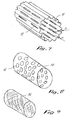
- Fig.7 shows the corrugated metal 11 existing reinforcement 10 alone, without the surrounding sealing sleeve 6a.
- the wave height h is about 10 to 30 times the wall thickness s of the corrugated sheet 11.
- the corrugated sheet 11 is provided with longitudinal slots 12, which give a good positive connection of the rubber-elastic material on the inside and outside. Through the slots 12 and the radial deformability of the corrugated sheet 11 is still improved.
- FIG. 8 shows a variant of the reinforcement 10 with a smooth sleeve 13, which is provided with distributed over its length and its circumference arranged holes 14. These holes 14 also serve the better connection of the sleeve 13 with the surrounding rubber-elastic material of the sealing sleeve 6a.
- FIG. 5 shows a sealing collar 6b with individual, longitudinally aligned rods 16a, which are embedded in the sealing sleeve 6b.
- the rods 16a also allow radial deformation of the sealing collar 6b and a high flexural rigidity in the longitudinal direction.
- bars 16b of a reinforcement are connected to a grid 18 by means of webs 17 extending transversely thereto.
- the cross section of the webs 17 is relatively small in relation to that of the rods 16. This also allows a good deformability of the sealing sleeve 6 in the radial direction and a high bending stiffness in the longitudinal direction.
- FIG. 10 Another embodiment of a reinforcement 10 according to the invention is shown in FIG.
- This reinforcement 10 consists of a fabric 15, for example of glass fibers or metallic wires.
- the fabric 15 may be circumferentially aligned or, for example, as shown, positioned at a certain angle to the longitudinal axis.
- combinations of the apparent from the individual figures versions can be formed.
Landscapes
- Engineering & Computer Science (AREA)
- General Engineering & Computer Science (AREA)
- Mechanical Engineering (AREA)
- Physics & Mathematics (AREA)
- Fluid Mechanics (AREA)
- Gasket Seals (AREA)
- Pressure Vessels And Lids Thereof (AREA)
- Orthopedics, Nursing, And Contraception (AREA)
Description
- Die Erfindung betrifft eine Rohrkupplung mit im wesentlichen zylindrischem, vorzugsweise aus metallischem Werkstoff bestehendem Gehäuse und einer zentrisch im Gehäuse angeordneten, im wesentlichen hülsenförmigen Dichtmanschette aus gummielastischem Werkstoff.
- Solche Rohrkupplungen dienen zum Verbinden glattendiger Rohre und Ar maturen. Je nach Bauweise der Rohrkupplungen können diese für zugfeste oder nicht zugfeste Rohrverbindungen eingesetzt werden. Rohrkupplungen werden je nach Bedarf sowohl für Druckleitungen als auch für Vakuumleitungen verwendet. Zwischen den zu verbindenden Rohren wird in der Regel ein axialer Abstand eingehalten, um Längenänderungen der Rohre infolge von Temperaturänderungen o.dgl. auszugleichen oder um zu vermeiden, dass die meistens metallischen Rohre unkontrolliert aneinander stossen und/oder Schwingungen übertragen.
- Bei vakuumführenden Leitungen besteht dabei die Gefahr, dass die Dichtmanschette infolge des Vakuums in den Rohrspalt eingesaugt und dabei beschädigt wird bzw. dadurch die Kupplung undicht wird. Bei Auswinkelungen, d.h. Verändern der Winkellage der mittels der Rohrkupplung verbundenen Rohre zueinander, besteht ebenfalls die Gefahr von Beschädigungen der Dichtmanschette.
- Um solche Beschädigungen zu vermeiden, ist es üblich, eine Bandeinlage aus Metall oder Kunststoff zentrisch in die Manschette einzusetzen. Diese Bandeinlage stützt somit bei Vakuumangriff die Manschette und steht in Kontakt mit dem Medium (z.B. Gase oder abgesaugte Flüssigkeiten) in der Rohrleitung und kann beispielsweise bei korrosiven Medien von diesen angegriffen werden, bzw. diese u.U. ungewollt dotieren.
- Eine sich lose in der Dichtmanschette befindliche Bandeinlage kann beim Transport oder bei der Handhabung der Kupplung herausfallen und dann bei der Montage der Kupplung vergessen werden. Alternativ müssen solche Bandeinlagen als Sonderzubehör geliefert werden, was einen zusätzlichen logistischen Aufwand bedeutet und ebenso vergessen werden könnte. Dies ist besonders schwerwiegend und sicherheitsrelevant, da bei einer fertig montierten Kupplung von aussen nicht erkennbar ist, ob eine Bandeinlage eingesetzt wurde.
- Aus der EP 0 066 825 B1 ist eine Rohrkupplung ersichtlich, bei der einzelne harte, relativ schmale Ringe in einige Ringabschnitte der Dichtmanschette eingebettet sind. Die Ringe liegen somit in Ebenen, die sich senkrecht zur axialen Richtung der Dichtmanschette erstrecken. Dadurch sollen bestimmte Bereiche der Manschette gegen Innendruck versteift werden, wie dies beispielsweise auch bei herkömmlichen Schläuchen bekannt ist. Bei dieser Rohrkupplung handelt es sich um eine sogenannte Ablaufschelle, welche für Ablaufrohre mit geringem Innendruck (bis max. 5 bar verwendet wird. Dabei weist das Gehäuse der Rohrkupplung eine extrem dünne Wandstärke auf, wird bei der Montage aufgebogen und um die Dichtmanschette herum gelegt. Bezüglich dem Entgegenwirken des Einsaugens der Dichtmanschette in den Rohrspalt haben diese einzelnen, relativ schmalen Ringe jedoch nur eine beschränkte Wirkung, da die Bereiche der Dichtmanschette zwischen den Ringen gegen ein Einsaugen in den freien Kupplungsraum nicht geschützt sind. Diese Rohrkupplung ist daher auch nicht für die Verwendung im Vakuum vorgesehen und ihre Anwendung ist für solche Zwecke dem Fachmann auch nicht nahegelegt.
- Der Erfindung liegt die Aufgabe zugrunde, eine Rohrkupplung zu schaffen deren Dichtmanschette auch bei grösseren Rohrspalten ohne den Einsatz einer zusätzlichen Bandeinlage gegen Beschädigung infolge Vakuumeinwirkung geschützt ist. Die Manschette soll somit beliebig für Innendruck und Aussendruck (Vakuum) einsetzbar sein.
- Erfindungsgemäss wird dies dadurch erreicht, dass die Dichtmanschette im Innern eine sich über einen wesentlichen Teil ihrer Länge in axialer Richtung erstreckende Armierung aufweist, wobei die Armierung in radialer Richtung verformbar ist und in Axialrichtung biegesteit ist.
- Durch die Armierung im Innern der Manschette kann die Anwendung einer Bandeinlage entfallen. Ausserdem kann die Wandstärke der Manschette geringer gehalten werden, was sich günstig auf die Herstellkosten auswirkt, da Gummi ein vergleichsweise teures Material ist. Weiters kann insbesondere auf bekannte Rippen oder Stege auf der Innenseite der Dichtmanschette verzichtet werden, was die Herstellformen für solche Manschetten vereinfacht.
- Durch die Verformbarkeit der Armierung in radialer Richtung ist auch die Verformbarkeit der gesamten Dichtmanschette in radialer Richtung gewährleistet. Diese ist wichtig bei Rohrkupplungen mit relativ steifem Gehäuse, da bei solchen Rohrkupplungen die Dichtmanschette an einer Stelle radial nach innen eingebuchtet und somit im Aussendurchmesser verkleinert wird, wonach sie in das Gehäuse eingesetzt werden und sich darin wieder entspannen kann.
- Die Armierung ist vorteilhafter als glattes oder im Querschnitt wellenförmiges Blech ausgebildet. Ein wellenförmiges Blech ist ohne grösseren Widerstand in radialer Richtung verformbar. In Längsrichtung der Dichtmanschette weist ein wellenförmiges Blech jedoch eine höhere Biegesteifigkeit auf.
- Die Wandstärke des Blechs beträgt zweckmässig etwa 0.1 bis 0.5 mm.
Durch diese relativ geringe Wandstärke des Blechs ist bei genügender Biegesteifigkeit die radiale Verformbarkeit gewährleistet. - Die Wellenhöhe des gewellten Blechs beträgt vorteilhaft das 10- bis 30-fache der Wandstärke. Durch dieses Verhältnis ergibt sich eine optimale Biegesteifigkeit bei gleichzeitiger Aufrechterhaltung der radialen Verformbarkeit.
- Das Blech weisst zweckmässig Perforationen auf. Solche Perforationen ergeben eine gute formschlüssige Verbindung des Blechs mit dem dieses auf beiden Seiten umgebenden gummielastischen Werkstoff.
- Die Perforationen sind vorteilhafter als runde Löcher oder als in axialer Richtung verlaufende Schlitze ausgebildet. Durch die Perforationen, insbesondere in der Form von Schlitzen, wird die radiale Verformbarkeit des Blechs noch vergrössert, ohne die Steifigkeit in Axialrichtung wesentlich zu beeinflussen.
- Eine weitere zweckmässige Ausführung besteht darin, dass die Armierung als Gewebe ausgebildet ist. Je nach Ausrichtung des Gewebes kann die radiale und axiale Verformbarkeit der Dichtmanschette entsprechend beeinflusst werden.
- Das Gewebe besteht vorteilhaft aus Fasern, beispielsweise Glasfasern oder Cord. Glasfasern weisen eine sehr hohe Zähigkeit und Festigkeit sowie eine gute Temperaturbeständigkeit auf. Alternativ stehen jedoch auch beliebige andere geeignete Fasern oder Corde, wie sie z.B. in der Pneuindustrie gang und gäbe sind zur Verfügung. Somit sind auch Polyamidfasern, Stahlcord, Kevlar®, Kohlenstofffasern o.dgl. je nach Detaileinsatz im Rahmen der Erfindung anwendbar.
- Eine zweckmässige Ausführung besteht darin, dass das Gewebe aus metallischen Drähten oder Metallcord besteht. Je nach Anforderungen können die Drähte unterschiedliche Drahtstärken und Federeigenschaften aufweisen.
- Die Armierung besteht alternativ vorteilhaft aus mehreren über den Umfang verteilt angeordneten, in axialer Richtung verlaufenden Stäben. Solche Stäbe ergeben praktisch keine Beeinträchtigung der radialen Verformbarkeit der Dichtmanschette.
- Die Stäbe bestehen zweckmässigerweise aus metallischem Werkstoff oder aus Kunststoff. Bei einer weiteren zweckmässigen Ausführung bestehen die Stäbe aus fasernverstärktem Kunststoff. Solche beispielsweise glasfasernverstärkte Kunststoffe weisen und ein geringes Gewicht und eine sehr hohe Festigkeit auf. Alternativ stehen beispielsweise auch Polyamid, Carbon oder Kevlar® zur Verfuegung.
- Um das Einlegen der Stäbe in die Vulkanisierform zum Herstellen der Dichtmanschette zu erleichtern, sind die Stäbe vorteilhaft über quer zur Längsrichtung der Stäbe verlaufende Stege zu einem Gitter verbunden. Ein solches Gitter kann beispielsweise ab Band als Meterware produziert und für die unterschiedlichen Durchmesser der Dichtmanschette entsprechend abgelängt werden.
- Der Querschnitt der Stege ist zweckmässiger weise geringer als derjenige der Stäbe. Die Stege weist somit im Unterschied zu derjenigen der Stäbe eine gute Verformbarkeit auf (Dies bedeutet somit genau das Gegenteil zu den bekannten und oben angegebenen Ring-Verstärkungen).
- Die Stege können vorteilhaft aus flexiblem Draht bestehen. Die Verbindung der aus Draht bestehenden Stege mit den Stäben kann beispielsweise durch Punktschweissungen oder durch Umwickeln der Stäbe mittels dem Draht erfolgen.
- Die Bezugszeichenliste und die Fig.1 bis Fig.9 bilden, zusammen mit den in den Ansprüchen beschriebenen, beziehungsweise geschützten Gegenständen, integrierende Bestandteile der Offenbarung dieser Anmeldung. Die Figuren werden zusammenhängend und übergreifend beschrieben. Gleiche Bezugszeichen bedeuten gleiche Bauteile, Bezugszeichen mit unterschiedlichen Indizes geben funktionengleiche Bauteile an.
- Die Erfindung soll nachstehend, anhand der sie beispielsweise wiedergebenden Zeichnungen näher erläutert werden. Es zeigen:
- Fig.1
- Eine Rohrkupplung in unverspanntem Zustand, in Stirnansicht,
- Fig.2
- eine Seitenansicht der in Fig.1 dargestellten Rohrkupplungen, teilweise im Schnitt dargestellt,
- Fig.3
- einen Querschnitt durch die in Fig.2 dargestellte Dichtmanschette,
- Fig.4
- einen Längsschnitt durch die Dichtmanschette gemäss Fig.3,
- Fig.5
- eine weitere Ausführung einer Erfindungsgemässen, teilweise aufgeschnittenen Dichtmanschette,
- Fig.6
- eine erfindungsgemässe Armierung für Dichtmanschetten,
- Fig.7
- eine weitere Ausführung einer Armierung für Dichtmanschetten und
- Fig.8
- eine Variante der in Fig.7 dargestellten Dichtmanschette und
- Fig.9
- Eine weitere Ausführung einer erfindungsgemässen Armierung für Dichtmanschetten
- Die aus Fig.1 und Fig.2 ersichtliche Rohrkupplung weist ein vorzugsweise aus metallischem Werkstoff bestehendes Gehäuse 1 mit angeformten Laschen 2 auf. In den Laschen 2 sind zylindrische Verschlussbolzen 3 angeordnet. Die Verschlussbolzen 3 werden von Spannschrauben 4 durchsetzt, welche ein Verspannen der Rohrkupplung auf den miteinander zu verbindenden Rohrenden ermöglichen.. Im Gehäuse 1 der Rohrkupplung sind Verankerungsringe 5 angeordnet, welche sich in den Ecken des Gehäuses 1 abstützen. Diese Verankerungsringe 5 ermöglichen ein zugfestes Verbinden von Rohren. Für nicht zugfeste Rohrverbindungen werden die Verankerungsringe 5 weggelassen.
- Im Gehäuse 1 ist eine aus einem gummielastischen Werkstoff bestehende Dichtmanschette 6a eingesetzt. Die Dichtmanschette 6a weist gegeneinander gerichtete Dichtlippen 7 auf, welche sich beim Montieren der Rohrkupplung an die Aussenseite der zu verbindenden Rohre anlegen und somit ein Abdichten des Rohrspaltes ermöglichen. Zwischen den Dichtlippen 7 befindet sich ein relativ dünnwandiger Steg 8, welcher bei Überdruck der Rohrleitung gegen die Wandung des Gehäuses 1 gepresst wird. Der Steg 8, die Dichtlippen 7 und die Rohre bilden zusammen einen Hohlraum 9 in welchen das in den Rohrleitung geführte Medium durch den Rohrspalt in diesen Hohlraum 9 eintreten kann. Bei Vakuum führenden Rohrleitungen entsteht in diesem Hohlraum 9 ebenfalls ein Unterdruck durch den der Steg 8 radial nach innen gezogen wird. Erfindungsgemäss wird dies verhindert durch eine in den gummielastischen Werkstoff der Dichtmanschette 6a eingebettete, sich über einen wesentlichen Teil ihrer Länge in axialer Richtung erstreckende Armierung 10.
- In Fig.3 und Fig.4 ist die Armierung als Wellblech 11 ausgebildet. Die Enden des Wellblechs 11 können miteinander zu einer Hülse verbunden werden oder offen bleiben. Das Wellblech 11 ermöglicht eine gute radiale Verformbarkeit der Dichtmanschette 6a. Durch den gewellten Querschnitt weist die Armierung 10 gleichzeitig in Längsrichtung eine hohe Biegesteifigkeit auf und ergibt somit eine optimale Verstärkung des Steges 8 der Dichtmanschette 6a.
- Fig.7 zeigt die aus Wellblech 11 bestehende Armierung 10 allein, ohne die sie umgebende Dichtmanschette 6a. Die Wellenhöhe h beträgt etwa das 10-bis 30-fache der Wandstärke s des Wellblechs 11. Das Wellblech 11 ist mit Längsschlitzen 12 versehen, welche eine gute formschlüssige Verbindung des gummielastischen Werkstoffes auf der Innen- und Aussenseite ergeben. Durch die Schlitze 12 wird auch die radiale Verformbarkeit des Wellblechs 11 noch verbessert.
- Fig.8 zeigt eine Variante der Armierung 10 mit einer glatten Hülse 13, welche mit über ihre Länge und ihren Umfang verteilt angeordneten Löchern 14 versehen ist. Diese Löcher 14 dienen ebenfalls der besseren Verbindung der Hülse 13 mit dem sie umgebenden gummielastischen Werkstoff der Dichtmanschette 6a.
- Fig.5 zeigt eine Dichtmanschette 6b mit einzelnen, in Längsrichtung ausgerichtete Stäben 16a, welche in die Dichtmanschette 6b eingebettet sind. Die Stäbe 16a ermöglichen ebenfalls eine radiale Verformung der Dichtmanschette 6b und eine hohe Biegesteifigkeit in Längsrichtung.
- Aus Fig.6 sind Stäbe 16b einer Armierung mittels quer dazu verlaufenden Stegen 17 zu einem Gitter 18 verbunden. Der Querschnitt der Stege 17 ist im Verhältnis zu demjenigen der Stäbe 16 relativ gering. Dies ermöglicht ebenfalls eine gute Verformbarkeit der Dichtmanschette 6 in radialer Richtung und eine hohe Biegesteifigkeit in Längsrichtung.
- Eine weitere Ausführung einer erfindungsgemässen Armierung 10 ist in Fig.9 dargestellt. Diese Armierung 10 besteht aus einem Gewebe 15, beispielsweise aus Glasfasern oder metallischen Drähten. Das Gewebe 15 kann in Umfangsrichtung ausgerichtet oder beispielsweise, wie dargestellt unter einem bestimmten Winkel zur Längsachse angeordnet werden.
- Gegebenenfalls können auch Kombinationen der aus den einzelnen Figuren ersichtlichen Ausführungen gebildet werden. So ist es beispielsweise möglich, ein Gitter 18 zusätzlich durch ein Gewebe 15 zu verstärken.
-
- 1
- Gehäuse
- 2
- Lasche
- 3
- Verschlussbolzen
- 4
- Spannschraube
- 5
- Verankerungsring
- 6a, 6b
- Dichtmanschette
- 7
- Dichtlippe
- 8
- Steg
- 9
- Hohlraum
- 10
- Armierung
- 11
- Wellblech
- 12
- Schnitze
- 13
- Hülse
- 14
- Löcher
- 15
- Gewebe
- 16a, 16b
- Stab
- 17
- Steg
- 18
- Gitter
Claims (16)
- Rohrkupplung mit im wesentlichen zylindrischem, vorzugsweise aus metallischem Werkstoff bestehendem Gehäuse und einer darin angeordneten, im wesentlichen hülsenförmigen Dichtmanschette aus gummielastischem Werkstoff, dadurch gekennzeichnet, dass die Dichtmanschette (6a, 6b) im Innern eine hülsenförmige oder stabförmige, sich über einen wesentlichen Teil ihrer Länge in axialer Richtung erstreckende Armierung (10, 11, 13, 18) aufweist, wobei die Armierung (10, 11, 13, 18) in radialer Richtung verformbar ist und in Axialrichtung biegesteif ist.
- Rohrkupplung nach Anspruch 1, dadurch gekennzeichnet, dass die Armierung als glattes oder im Querschnitt wellenförmiges Blech (11, 13) ausgebildet ist.
- Rohrkupplung nach Anspruch 2, dadurch gekennzeichnet, dass die Wandstärke (s) des Blechs 0,05mm bis 1,0 mm beträgt.
- Rohrkupplung nach einem der Ansprüche 2 oder 3, dadurch gekennzeichnet, dass die Wellenhöhe (h) des gewellten Blechs (11) das 5 bis 30-fache der Wandstärke (s) beträgt.
- Rohrkupplung nach einem der Ansprüche 2 bis 4, dadurch gekennzeichnet, dass das Blech (11, 13) Perforationen (12, 14) aufweist.
- Rohrkupplung nach Anspruch 5, dadurch gekennzeichnet, dass die Perforationen als runde Löcher (14) oder als in axialer Richtung verlaufende Schlitze (12) ausgebildet sind.
- Rohrkupplung nach einem der vorhergehenden Ansprüche , dadurch gekennzeichnet, dass die Armierung als Gewebe (15) ausgebildet ist.
- Rohrkupplung nach Anspruch 7, dadurch gekennzeichnet, dass das Gewebe (15) aus Fasern oder Cord besteht.
- Rohrkupplung nach Anspruch 7 oder 8, dadurch gekennzeichnet, dass das Gewebe (15) aus metallischen Drähten oder Metallcord besteht.
- Rohrkupplung nach einem der vorhergehenden Ansprüche , dadurch gekennzeichnet, dass die Armierung aus mehreren über den Umfang verteilt angeordneten, in axialer Richtung verlaufenden Stäben (16a, 16b) besteht.
- Rohrkupplung nach Anspruch 10, dadurch gekennzeichnet, dass die Stäbe (16a, 16b) aus einem metallischen Werkstoff bestehen.
- Rohrkupplung nach Anspruch 10, dadurch gekennzeichnet, dass die Stäbe (16a, 16b) aus Kunststoff bestehen.
- Rohrkupplung nach Anspruch 12, dadurch gekennzeichnet, dass die Stäbe (16a, 16b) aus faserverstärktem Kunststoff bestehen.
- Rohrkupplung nach einem der Ansprüche 10 bis 13, dadurch gekennzeichnet, dass die Stäbe (16b) über quer zur Längsrichtung der Stäbe verlaufende Stege (17) zu einem Gitter (18) verbunden sind.
- Rohrkupplung nach Anspruch 14, dadurch gekennzeichnet, dass der Querschnitt der Stege (17) wesentlich geringer ist als derjenige der Stäbe (16b).
- Rohrkupplung nach Anspruch 14 oder 15, dadurch gekennzeichnet, dass die Stege (17) aus flexiblem Draht bestehen.
Applications Claiming Priority (3)
| Application Number | Priority Date | Filing Date | Title |
|---|---|---|---|
| CH306032003 | 2003-02-27 | ||
| CH3062003 | 2003-02-27 | ||
| PCT/IB2004/000470 WO2004076905A1 (de) | 2003-02-27 | 2004-02-25 | Rohrkupplung mit gummielastischer dichtmanschette |
Publications (2)
| Publication Number | Publication Date |
|---|---|
| EP1599690A1 EP1599690A1 (de) | 2005-11-30 |
| EP1599690B1 true EP1599690B1 (de) | 2006-09-20 |
Family
ID=32913656
Family Applications (1)
| Application Number | Title | Priority Date | Filing Date |
|---|---|---|---|
| EP04714377A Expired - Lifetime EP1599690B1 (de) | 2003-02-27 | 2004-02-25 | Rohrkupplung mit gummielastischer dichtmanschette |
Country Status (4)
| Country | Link |
|---|---|
| EP (1) | EP1599690B1 (de) |
| AT (1) | ATE340328T1 (de) |
| DE (1) | DE502004001535D1 (de) |
| WO (1) | WO2004076905A1 (de) |
Cited By (1)
| Publication number | Priority date | Publication date | Assignee | Title |
|---|---|---|---|---|
| US11193611B2 (en) | 2019-10-14 | 2021-12-07 | Fernco, Inc. | Pipe coupling apparatus |
Families Citing this family (1)
| Publication number | Priority date | Publication date | Assignee | Title |
|---|---|---|---|---|
| DE202011107927U1 (de) * | 2011-11-16 | 2013-02-20 | M.D.S. Meyer Gmbh | Verbindungsvorrichtung zum Verbinden von zwei Rohren |
Family Cites Families (3)
| Publication number | Priority date | Publication date | Assignee | Title |
|---|---|---|---|---|
| US400600A (en) * | 1889-04-02 | Insulating pipe-coupling | ||
| US3453006A (en) * | 1966-03-28 | 1969-07-01 | C & L Ind Inc | Conduit coupling |
| DE3122708C2 (de) * | 1981-06-06 | 1983-04-21 | Rasmussen Gmbh, 6457 Maintal | Gummimuffe für eine Breitbandschelle |
-
2004
- 2004-02-25 EP EP04714377A patent/EP1599690B1/de not_active Expired - Lifetime
- 2004-02-25 DE DE502004001535T patent/DE502004001535D1/de not_active Expired - Fee Related
- 2004-02-25 WO PCT/IB2004/000470 patent/WO2004076905A1/de not_active Ceased
- 2004-02-25 AT AT04714377T patent/ATE340328T1/de not_active IP Right Cessation
Cited By (1)
| Publication number | Priority date | Publication date | Assignee | Title |
|---|---|---|---|---|
| US11193611B2 (en) | 2019-10-14 | 2021-12-07 | Fernco, Inc. | Pipe coupling apparatus |
Also Published As
| Publication number | Publication date |
|---|---|
| WO2004076905A1 (de) | 2004-09-10 |
| EP1599690A1 (de) | 2005-11-30 |
| DE502004001535D1 (de) | 2006-11-02 |
| ATE340328T1 (de) | 2006-10-15 |
Similar Documents
| Publication | Publication Date | Title |
|---|---|---|
| DE4127039C2 (de) | Schnellanschlußverbinder für Plastikschläuche | |
| EP2603728B1 (de) | System zur abdichtung eines rohrleitungssystems | |
| DE10334775A1 (de) | Schlauch mit metallischem Wellrohr | |
| EP1599691B1 (de) | Schlauch mit eingebauter kupplung und verfahren zu seiner herstellung | |
| DE202008008421U1 (de) | Steckverbindung für Fluid-Leitungen | |
| DE102007050655A1 (de) | Wellenschlauch | |
| EP2154409A1 (de) | Rohr für eine aus mehreren miteinander zu verbindenden bestehende Rohrleitung und Verfahren zur Verbindung von derartigen Rohren | |
| DE102008021326A1 (de) | Flexible Rohrkupplung | |
| EP1599690B1 (de) | Rohrkupplung mit gummielastischer dichtmanschette | |
| DE102018205891B3 (de) | Durch Fluidbeaufschlagung aktivierbare Betätigungseinrichtung mit Rastmechanismus | |
| DE202008014425U1 (de) | Mehrkanalschlauch | |
| DE102010034679A1 (de) | Dickstoffpumpe | |
| DE102008034777B4 (de) | Luftkanalanordnung für ein Luftleitungssystem eines Flugzeugs | |
| DE102006030138B3 (de) | Teleskopierbares Staubsauger-Saugrohr | |
| EP3712479B1 (de) | Montage einer leitung an oder in einer öffnung | |
| DE202011000678U1 (de) | Dichtmanschette und Übergangskupplung mit Dichtmanschette | |
| DE102005026576A1 (de) | Verbindungs- und Anschlussstück für einen Wellenschlauch | |
| EP3885625B1 (de) | Wellrohrverbindungsanordnung | |
| DE2834136C2 (de) | ||
| EP0108722A1 (de) | Rohrmuffe | |
| EP0895015B1 (de) | Schlauch, insbesondere Kraftfahrzeug-Kühlwasserschlauch | |
| DE19533492A1 (de) | Biegsame Schlauchleitung | |
| DE60216093T2 (de) | Rohrverbindung | |
| DE102016103848B4 (de) | Flexibles Leitungsteil | |
| WO2024114861A1 (de) | Abschlussvorrichtung einer faserverbundwerkstoffstruktur |
Legal Events
| Date | Code | Title | Description |
|---|---|---|---|
| PUAI | Public reference made under article 153(3) epc to a published international application that has entered the european phase |
Free format text: ORIGINAL CODE: 0009012 |
|
| 17P | Request for examination filed |
Effective date: 20050927 |
|
| AK | Designated contracting states |
Kind code of ref document: A1 Designated state(s): AT BE BG CH CY CZ DE DK EE ES FI FR GB GR HU IE IT LI LU MC NL PT RO SE SI SK TR |
|
| AX | Request for extension of the european patent |
Extension state: AL LT LV MK |
|
| GRAP | Despatch of communication of intention to grant a patent |
Free format text: ORIGINAL CODE: EPIDOSNIGR1 |
|
| DAX | Request for extension of the european patent (deleted) | ||
| GRAS | Grant fee paid |
Free format text: ORIGINAL CODE: EPIDOSNIGR3 |
|
| GRAA | (expected) grant |
Free format text: ORIGINAL CODE: 0009210 |
|
| AK | Designated contracting states |
Kind code of ref document: B1 Designated state(s): AT BE BG CH CY CZ DE DK EE ES FI FR GB GR HU IE IT LI LU MC NL PT RO SE SI SK TR |
|
| PG25 | Lapsed in a contracting state [announced via postgrant information from national office to epo] |
Ref country code: CZ Free format text: LAPSE BECAUSE OF FAILURE TO SUBMIT A TRANSLATION OF THE DESCRIPTION OR TO PAY THE FEE WITHIN THE PRESCRIBED TIME-LIMIT Effective date: 20060920 Ref country code: SK Free format text: LAPSE BECAUSE OF FAILURE TO SUBMIT A TRANSLATION OF THE DESCRIPTION OR TO PAY THE FEE WITHIN THE PRESCRIBED TIME-LIMIT Effective date: 20060920 Ref country code: SI Free format text: LAPSE BECAUSE OF FAILURE TO SUBMIT A TRANSLATION OF THE DESCRIPTION OR TO PAY THE FEE WITHIN THE PRESCRIBED TIME-LIMIT Effective date: 20060920 Ref country code: RO Free format text: LAPSE BECAUSE OF FAILURE TO SUBMIT A TRANSLATION OF THE DESCRIPTION OR TO PAY THE FEE WITHIN THE PRESCRIBED TIME-LIMIT Effective date: 20060920 Ref country code: NL Free format text: LAPSE BECAUSE OF FAILURE TO SUBMIT A TRANSLATION OF THE DESCRIPTION OR TO PAY THE FEE WITHIN THE PRESCRIBED TIME-LIMIT Effective date: 20060920 Ref country code: IE Free format text: LAPSE BECAUSE OF FAILURE TO SUBMIT A TRANSLATION OF THE DESCRIPTION OR TO PAY THE FEE WITHIN THE PRESCRIBED TIME-LIMIT Effective date: 20060920 Ref country code: FI Free format text: LAPSE BECAUSE OF FAILURE TO SUBMIT A TRANSLATION OF THE DESCRIPTION OR TO PAY THE FEE WITHIN THE PRESCRIBED TIME-LIMIT Effective date: 20060920 Ref country code: IT Free format text: LAPSE BECAUSE OF FAILURE TO SUBMIT A TRANSLATION OF THE DESCRIPTION OR TO PAY THE FEE WITHIN THE PRESCRIBED TIME-LIMIT;WARNING: LAPSES OF ITALIAN PATENTS WITH EFFECTIVE DATE BEFORE 2007 MAY HAVE OCCURRED AT ANY TIME BEFORE 2007. THE CORRECT EFFECTIVE DATE MAY BE DIFFERENT FROM THE ONE RECORDED. Effective date: 20060920 |
|
| REG | Reference to a national code |
Ref country code: GB Ref legal event code: FG4D Free format text: NOT ENGLISH |
|
| REG | Reference to a national code |
Ref country code: CH Ref legal event code: EP |
|
| REG | Reference to a national code |
Ref country code: IE Ref legal event code: FG4D Free format text: LANGUAGE OF EP DOCUMENT: GERMAN |
|
| REF | Corresponds to: |
Ref document number: 502004001535 Country of ref document: DE Date of ref document: 20061102 Kind code of ref document: P |
|
| REG | Reference to a national code |
Ref country code: CH Ref legal event code: NV Representative=s name: ROSENICH PAUL; GISLER CHRISTIAN PATENTBUERO PAUL R |
|
| PG25 | Lapsed in a contracting state [announced via postgrant information from national office to epo] |
Ref country code: SE Free format text: LAPSE BECAUSE OF FAILURE TO SUBMIT A TRANSLATION OF THE DESCRIPTION OR TO PAY THE FEE WITHIN THE PRESCRIBED TIME-LIMIT Effective date: 20061220 Ref country code: DK Free format text: LAPSE BECAUSE OF FAILURE TO SUBMIT A TRANSLATION OF THE DESCRIPTION OR TO PAY THE FEE WITHIN THE PRESCRIBED TIME-LIMIT Effective date: 20061220 Ref country code: BG Free format text: LAPSE BECAUSE OF FAILURE TO SUBMIT A TRANSLATION OF THE DESCRIPTION OR TO PAY THE FEE WITHIN THE PRESCRIBED TIME-LIMIT Effective date: 20061220 |
|
| PG25 | Lapsed in a contracting state [announced via postgrant information from national office to epo] |
Ref country code: ES Free format text: LAPSE BECAUSE OF FAILURE TO SUBMIT A TRANSLATION OF THE DESCRIPTION OR TO PAY THE FEE WITHIN THE PRESCRIBED TIME-LIMIT Effective date: 20061231 |
|
| GBT | Gb: translation of ep patent filed (gb section 77(6)(a)/1977) |
Effective date: 20061219 |
|
| PG25 | Lapsed in a contracting state [announced via postgrant information from national office to epo] |
Ref country code: MC Free format text: LAPSE BECAUSE OF NON-PAYMENT OF DUE FEES Effective date: 20070228 |
|
| NLV1 | Nl: lapsed or annulled due to failure to fulfill the requirements of art. 29p and 29m of the patents act | ||
| PG25 | Lapsed in a contracting state [announced via postgrant information from national office to epo] |
Ref country code: PT Free format text: LAPSE BECAUSE OF FAILURE TO SUBMIT A TRANSLATION OF THE DESCRIPTION OR TO PAY THE FEE WITHIN THE PRESCRIBED TIME-LIMIT Effective date: 20070312 |
|
| REG | Reference to a national code |
Ref country code: IE Ref legal event code: FD4D |
|
| EN | Fr: translation not filed | ||
| PLBE | No opposition filed within time limit |
Free format text: ORIGINAL CODE: 0009261 |
|
| STAA | Information on the status of an ep patent application or granted ep patent |
Free format text: STATUS: NO OPPOSITION FILED WITHIN TIME LIMIT |
|
| 26N | No opposition filed |
Effective date: 20070621 |
|
| BERE | Be: lapsed |
Owner name: STRAUB WERKE A.G. Effective date: 20070228 |
|
| PG25 | Lapsed in a contracting state [announced via postgrant information from national office to epo] |
Ref country code: BE Free format text: LAPSE BECAUSE OF NON-PAYMENT OF DUE FEES Effective date: 20070228 |
|
| PG25 | Lapsed in a contracting state [announced via postgrant information from national office to epo] |
Ref country code: GR Free format text: LAPSE BECAUSE OF FAILURE TO SUBMIT A TRANSLATION OF THE DESCRIPTION OR TO PAY THE FEE WITHIN THE PRESCRIBED TIME-LIMIT Effective date: 20061221 Ref country code: FR Free format text: LAPSE BECAUSE OF FAILURE TO SUBMIT A TRANSLATION OF THE DESCRIPTION OR TO PAY THE FEE WITHIN THE PRESCRIBED TIME-LIMIT Effective date: 20070518 |
|
| PG25 | Lapsed in a contracting state [announced via postgrant information from national office to epo] |
Ref country code: AT Free format text: LAPSE BECAUSE OF NON-PAYMENT OF DUE FEES Effective date: 20070225 |
|
| PG25 | Lapsed in a contracting state [announced via postgrant information from national office to epo] |
Ref country code: EE Free format text: LAPSE BECAUSE OF FAILURE TO SUBMIT A TRANSLATION OF THE DESCRIPTION OR TO PAY THE FEE WITHIN THE PRESCRIBED TIME-LIMIT Effective date: 20060920 |
|
| PG25 | Lapsed in a contracting state [announced via postgrant information from national office to epo] |
Ref country code: FR Free format text: LAPSE BECAUSE OF FAILURE TO SUBMIT A TRANSLATION OF THE DESCRIPTION OR TO PAY THE FEE WITHIN THE PRESCRIBED TIME-LIMIT Effective date: 20060920 |
|
| PGFP | Annual fee paid to national office [announced via postgrant information from national office to epo] |
Ref country code: DE Payment date: 20090227 Year of fee payment: 6 |
|
| PGFP | Annual fee paid to national office [announced via postgrant information from national office to epo] |
Ref country code: CH Payment date: 20090108 Year of fee payment: 6 Ref country code: GB Payment date: 20090223 Year of fee payment: 6 |
|
| PG25 | Lapsed in a contracting state [announced via postgrant information from national office to epo] |
Ref country code: CY Free format text: LAPSE BECAUSE OF FAILURE TO SUBMIT A TRANSLATION OF THE DESCRIPTION OR TO PAY THE FEE WITHIN THE PRESCRIBED TIME-LIMIT Effective date: 20060920 Ref country code: LU Free format text: LAPSE BECAUSE OF NON-PAYMENT OF DUE FEES Effective date: 20070225 |
|
| PG25 | Lapsed in a contracting state [announced via postgrant information from national office to epo] |
Ref country code: HU Free format text: LAPSE BECAUSE OF FAILURE TO SUBMIT A TRANSLATION OF THE DESCRIPTION OR TO PAY THE FEE WITHIN THE PRESCRIBED TIME-LIMIT Effective date: 20070321 Ref country code: TR Free format text: LAPSE BECAUSE OF FAILURE TO SUBMIT A TRANSLATION OF THE DESCRIPTION OR TO PAY THE FEE WITHIN THE PRESCRIBED TIME-LIMIT Effective date: 20060920 |
|
| REG | Reference to a national code |
Ref country code: CH Ref legal event code: PL |
|
| GBPC | Gb: european patent ceased through non-payment of renewal fee |
Effective date: 20100225 |
|
| PG25 | Lapsed in a contracting state [announced via postgrant information from national office to epo] |
Ref country code: LI Free format text: LAPSE BECAUSE OF NON-PAYMENT OF DUE FEES Effective date: 20100228 Ref country code: CH Free format text: LAPSE BECAUSE OF NON-PAYMENT OF DUE FEES Effective date: 20100228 |
|
| PG25 | Lapsed in a contracting state [announced via postgrant information from national office to epo] |
Ref country code: DE Free format text: LAPSE BECAUSE OF NON-PAYMENT OF DUE FEES Effective date: 20100901 |
|
| PG25 | Lapsed in a contracting state [announced via postgrant information from national office to epo] |
Ref country code: GB Free format text: LAPSE BECAUSE OF NON-PAYMENT OF DUE FEES Effective date: 20100225 |