EP1871237B1 - Hand triggered tissue sealant spray apparatus and system - Google Patents
Hand triggered tissue sealant spray apparatus and system Download PDFInfo
- Publication number
- EP1871237B1 EP1871237B1 EP06718085A EP06718085A EP1871237B1 EP 1871237 B1 EP1871237 B1 EP 1871237B1 EP 06718085 A EP06718085 A EP 06718085A EP 06718085 A EP06718085 A EP 06718085A EP 1871237 B1 EP1871237 B1 EP 1871237B1
- Authority
- EP
- European Patent Office
- Prior art keywords
- gas
- sealant
- actuating member
- applicator assembly
- passageway
- Prior art date
- Legal status (The legal status is an assumption and is not a legal conclusion. Google has not performed a legal analysis and makes no representation as to the accuracy of the status listed.)
- Expired - Lifetime
Links
Images


Classifications
-
- A—HUMAN NECESSITIES
- A61—MEDICAL OR VETERINARY SCIENCE; HYGIENE
- A61J—CONTAINERS SPECIALLY ADAPTED FOR MEDICAL OR PHARMACEUTICAL PURPOSES; DEVICES OR METHODS SPECIALLY ADAPTED FOR BRINGING PHARMACEUTICAL PRODUCTS INTO PARTICULAR PHYSICAL OR ADMINISTERING FORMS; DEVICES FOR ADMINISTERING FOOD OR MEDICINES ORALLY; BABY COMFORTERS; DEVICES FOR RECEIVING SPITTLE
- A61J1/00—Containers specially adapted for medical or pharmaceutical purposes
- A61J1/05—Containers specially adapted for medical or pharmaceutical purposes for collecting, storing or administering blood, plasma or medical fluids ; Infusion or perfusion containers
-
- B—PERFORMING OPERATIONS; TRANSPORTING
- B05—SPRAYING OR ATOMISING IN GENERAL; APPLYING FLUENT MATERIALS TO SURFACES, IN GENERAL
- B05B—SPRAYING APPARATUS; ATOMISING APPARATUS; NOZZLES
- B05B7/00—Spraying apparatus for discharge of liquids or other fluent materials from two or more sources, e.g. of liquid and air, of powder and gas
- B05B7/02—Spray pistols; Apparatus for discharge
- B05B7/04—Spray pistols; Apparatus for discharge with arrangements for mixing liquids or other fluent materials before discharge
- B05B7/0408—Spray pistols; Apparatus for discharge with arrangements for mixing liquids or other fluent materials before discharge with arrangements for mixing two or more liquids
-
- A—HUMAN NECESSITIES
- A61—MEDICAL OR VETERINARY SCIENCE; HYGIENE
- A61B—DIAGNOSIS; SURGERY; IDENTIFICATION
- A61B17/00—Surgical instruments, devices or methods
- A61B17/00491—Surgical glue applicators
-
- B—PERFORMING OPERATIONS; TRANSPORTING
- B05—SPRAYING OR ATOMISING IN GENERAL; APPLYING FLUENT MATERIALS TO SURFACES, IN GENERAL
- B05B—SPRAYING APPARATUS; ATOMISING APPARATUS; NOZZLES
- B05B7/00—Spraying apparatus for discharge of liquids or other fluent materials from two or more sources, e.g. of liquid and air, of powder and gas
- B05B7/02—Spray pistols; Apparatus for discharge
- B05B7/04—Spray pistols; Apparatus for discharge with arrangements for mixing liquids or other fluent materials before discharge
- B05B7/0416—Spray pistols; Apparatus for discharge with arrangements for mixing liquids or other fluent materials before discharge with arrangements for mixing one gas and one liquid
- B05B7/0483—Spray pistols; Apparatus for discharge with arrangements for mixing liquids or other fluent materials before discharge with arrangements for mixing one gas and one liquid with gas and liquid jets intersecting in the mixing chamber
-
- B—PERFORMING OPERATIONS; TRANSPORTING
- B05—SPRAYING OR ATOMISING IN GENERAL; APPLYING FLUENT MATERIALS TO SURFACES, IN GENERAL
- B05C—APPARATUS FOR APPLYING FLUENT MATERIALS TO SURFACES, IN GENERAL
- B05C17/00—Hand tools or apparatus using hand held tools, for applying liquids or other fluent materials to, for spreading applied liquids or other fluent materials on, or for partially removing applied liquids or other fluent materials from, surfaces
- B05C17/005—Hand tools or apparatus using hand held tools, for applying liquids or other fluent materials to, for spreading applied liquids or other fluent materials on, or for partially removing applied liquids or other fluent materials from, surfaces for discharging material from a reservoir or container located in or on the hand tool through an outlet orifice by pressure without using surface contacting members like pads or brushes
- B05C17/00503—Details of the outlet element
- B05C17/00516—Shape or geometry of the outlet orifice or the outlet element
-
- B—PERFORMING OPERATIONS; TRANSPORTING
- B05—SPRAYING OR ATOMISING IN GENERAL; APPLYING FLUENT MATERIALS TO SURFACES, IN GENERAL
- B05C—APPARATUS FOR APPLYING FLUENT MATERIALS TO SURFACES, IN GENERAL
- B05C17/00—Hand tools or apparatus using hand held tools, for applying liquids or other fluent materials to, for spreading applied liquids or other fluent materials on, or for partially removing applied liquids or other fluent materials from, surfaces
- B05C17/005—Hand tools or apparatus using hand held tools, for applying liquids or other fluent materials to, for spreading applied liquids or other fluent materials on, or for partially removing applied liquids or other fluent materials from, surfaces for discharging material from a reservoir or container located in or on the hand tool through an outlet orifice by pressure without using surface contacting members like pads or brushes
- B05C17/00553—Hand tools or apparatus using hand held tools, for applying liquids or other fluent materials to, for spreading applied liquids or other fluent materials on, or for partially removing applied liquids or other fluent materials from, surfaces for discharging material from a reservoir or container located in or on the hand tool through an outlet orifice by pressure without using surface contacting members like pads or brushes with means allowing the stock of material to consist of at least two different components
-
- B—PERFORMING OPERATIONS; TRANSPORTING
- B05—SPRAYING OR ATOMISING IN GENERAL; APPLYING FLUENT MATERIALS TO SURFACES, IN GENERAL
- B05C—APPARATUS FOR APPLYING FLUENT MATERIALS TO SURFACES, IN GENERAL
- B05C17/00—Hand tools or apparatus using hand held tools, for applying liquids or other fluent materials to, for spreading applied liquids or other fluent materials on, or for partially removing applied liquids or other fluent materials from, surfaces
- B05C17/005—Hand tools or apparatus using hand held tools, for applying liquids or other fluent materials to, for spreading applied liquids or other fluent materials on, or for partially removing applied liquids or other fluent materials from, surfaces for discharging material from a reservoir or container located in or on the hand tool through an outlet orifice by pressure without using surface contacting members like pads or brushes
- B05C17/015—Hand tools or apparatus using hand held tools, for applying liquids or other fluent materials to, for spreading applied liquids or other fluent materials on, or for partially removing applied liquids or other fluent materials from, surfaces for discharging material from a reservoir or container located in or on the hand tool through an outlet orifice by pressure without using surface contacting members like pads or brushes with pneumatically or hydraulically actuated piston or the like
-
- A—HUMAN NECESSITIES
- A61—MEDICAL OR VETERINARY SCIENCE; HYGIENE
- A61B—DIAGNOSIS; SURGERY; IDENTIFICATION
- A61B17/00—Surgical instruments, devices or methods
- A61B17/00491—Surgical glue applicators
- A61B2017/00495—Surgical glue applicators for two-component glue
Definitions
- This invention relates to a system for applying tissue sealant, such as tissue sealant, to a work surface, such as biological tissue.
- sealant in the form of tissue sealants have been applied to human and animal tissue, for example, to seal or repair tissue at a surgical or wound site, to stop bleeding, seal wounds, treat burns or skin grafts and a variety of other purposes.
- tissue sealant has typically been applied by a syringe-type applicator that ejects tissue sealant directly onto the tissue.
- a syringe-type applicator that ejects tissue sealant directly onto the tissue.
- Examples of such applicators are shown in U.S. Patent Nos. 4,846,405 , 5,582,596 , 5,665,067 , 6,461,361 and 6,585,696 , PCT Publication Nos. WO 96/39212 WO 95/31138 and WO 97/20585 and European publication no. EP-A-0, 634, 140 . Further examples of such applicators also are sold under the Tissomat and Duploject trademarks, which are marketed by Baxter AG.
- the tissue sealant employed in treating biological tissue is typically made of one or more components, such as biocompatible compounds that can be absorbed by the body and do not require later removal from the patient.
- One example of a known tissue sealant is made of fibrinogen and thrombin.
- the tissue sealant may be contained in more than one container which can be mixed into an adhesive combination upon ejection from the tissue sealant applicator.
- the components may exit from two separate outlets positioned in proximity with one another so that these components are mixed to create an adhesive tissue sealant upon ejection from the applicator.
- Tissue sealant applicators also may provide tissue sealant that is atomized by means of pressurized, sterile gas such as, for example, air, to form a spray which is a combination of tissue sealant and a sterile gas or air.
- the applicator is connected to an air or gas source by tubing that supplies the gas or air to the distal end of the applicator in the vicinity of the outlets of the one or more tissue sealant components.
- gas may communicate with one or more of the tissue sealant components within a mixing area defined by the applicator.
- the gas may mix with the tissue sealant components after ejection from the applicator.
- the gas or air outlet preferably is located in close proximity to the outlets of one or more of the tissue sealant components and may, for example, be in the form of an annular shaped outlet which surrounds at least one of the tissue sealant component outlets.
- the supply of gas or air is preferably coordinated so that, for example, gas is essentially simultaneously supplied to the applicator upon ejection of tissue sealant.
- gas is essentially simultaneously supplied to the applicator upon ejection of tissue sealant.
- synchronizing the timing of this supply with the ejection of tissue sealant or its components has proven awkward and difficult, particularly where multiple tissue sealant components are used.
- tissue sealant applicators have relied on the user, such as a surgeon or hospital staff member, to simultaneously activate the supply of gas with the ejection of tissue sealant with separate motions.
- the user is required to manually turn on and off the supply of gas, such as by foot actuation, in addition to the separate movement required to manually eject tissue sealant or components, such as, for example, by pressing on a syringe plunger or the like. It has proven difficult for the user to coordinate the timing of these two separate motions. Therefore, it is desired to provide a tissue sealant applicator which simplifies activation of a spray discharge of tissue sealant and which further provides a reliable and continuous spray discharge of tissue sealant.
- the present invention provides a sealant applicator assembly according to claim 1.
- the present invention is generally directed to a system and apparatus for applying or, an apparatus for use in applying, sealant, such as tissue sealant, to a work surface, such as biological tissue, in which a supply of gas may be reliably actuated essentially simultaneously with the ejection of the sealant.
- sealant such as tissue sealant
- a sealant applicator assembly for use with an apparatus of the type having an elongated body defining an interior bore for containing sealant, for example, tissue sealant, and having proximal and distal ends.
- the apparatus further includes a piston movably positioned in the bore and a pusher member operatively associated with the piston and extending through the proximal end of the bore.
- the sealant applicator assembly comprises a spray adaptor which is adapted to communicate with the bore of the body and defines a distal outlet.
- the sealant applicator assembly further comprises a first gas passageway which is cooperatively associated with the distal outlet and is configured to direct gas to create a spray discharge of the sealant.
- An actuating member is adapted to be cooperatively associated with the pusher member for moving the piston toward the distal end of the body to eject sealant through the distal outlet and operative to simultaneously actuate a supply of gas to the first gas passageway for creating a spray discharge of sealant.
- a control unit is provided.
- the control unit is operable upon receipt of a control signal from the apparatus to activate a flow of gas suitable for communication with the first gas passageway to create a spray discharge of sealant.
- the actuating member is operatively connected to the gas supply source to at least selectively actuate the flow of gas through the first gas passageway to create a spray discharge of sealant for application to the work surface.
- the applicator assembly is cooperatively associated with a gas supplying device adapted to controllably supply a pressurized source of gas through a first gas outlet and also having an input to receive a supply signal and control the supply of the source of gas in at least partial dependence on the signal.
- the applicator assembly further comprises tubing in fluid communication with the first gas passageway and adapted to be placed in fluid communication with the first gas outlet.
- the actuating member is configured to generate the supply signal during movement of the pusher such that gas is supplied from the first gas outlet in at least partial dependence on the signal.
- the applicator assembly comprises a first apparatus comprising an elongated body defining an interior bore for containing sealant and having proximal and distal ends.
- a piston is movably positioned in the bore, and a pusher member operatively associated with the piston extending through the proximal end of the bore.
- Such applicator assembly also comprises a gas supplying device having a first gas outlet, a supply signal input to receive a supply signal, a switch to actuate a flow of gas to the first gas outlet, and a control mechanism to cooperatively associate the switch and a signal supplied to the supply signal input.
- the applicator assembly comprises an apparatus comprising an elongated body defining an interior bore for containing sealant and having proximal and distal ends, a piston movably positioned in the bore, and a pusher member operatively associated with the piston extending through the proximal end of the bore, wherein the pusher member is adapted to be cooperatively associated with an actuating member of the applicator assembly. Additional aspects or features of the present invention may be set forth in the following description.
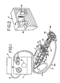
- Fig. 1 is a top perspective view of an apparatus, with portions of the apparatus being shown as transparent to aid illustration, and also includes a sealant applicator assembly, a control unit, and a gas supply source, shown schematically.
- Fig. 2 is a back perspective view of the control unit shown in Fig. 1 .
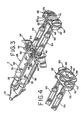
- Fig. 3 is an enlarged top perspective view of the apparatus shown in Fig. 1 .
- Fig. 4 is a partial enlarged top perspective view of the proximal end of the apparatus shown in Fig. 1 .
- Fig. 5 is a bottom perspective view of the apparatus shown in Fig. 1 .
- Fig. 6 is a front perspective view of an actuating member of the apparatus.
- Fig. 7 is a back perspective view of the actuating member.
- Fig. 8 is a top view of the apparatus in Fig. 1 .
- Fig. 9 is a side view of the apparatus shown in Fig. 1 .
- Fig. 10 is a partial enlarged bottom view of the proximal end of the apparatus shown in Fig. 1 .
- Fig. 11 is a front view of a pusher member shown in Fig. 1 .
- Fig. 12 is a sectional view along line 12-12 of Fig. 11 .
- Fig. 13 is a rear view of the pusher member.
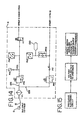
- Fig. 14 is a pneumatic diagram of the control unit shown in Fig. 1 .
- Fig. 15 is a flow chart of an electrical circuit employed in the control unit.
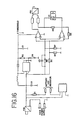
- Fig. 16 is a schematic of an electrical circuit employed in the control unit.
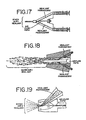
- Fig. 17 shows a modified spray adaptor in which gas mixes with one of the sealant components.
- Fig. 18 shows another modified spray adaptor in which gas separately mixes with each of the sealant components.
- Fig. 19 shows yet another modified spray adaptor in which gas mixes with both of the sealant components after the components are mixed together.
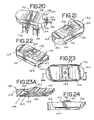
- Fig. 20 is a top perspective view of an alternative actuating member, with portions of the apparatus being shown removed to aid illustration.
- Fig. 21 is a right side perspective view of the actuating member shown in Fig. 20 .
- Fig. 22 is a left side perspective view of the actuating member shown in Fig. 20 .
- Fig. 23 is a top view of the actuating member shown in Fig. 20 .
- Fig. 23A is a cross-sectional view taken along plane 23A shown in Fig. 23 .
- Fig. 24 is a rear view of the actuating member shown in Fig. 20 .
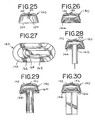
- Fig. 25 is a right side view of the actuating member shown in Fig. 20 .
- Fig 26 is a left side view of the actuating member shown in Fig. 20 .
- Fig. 27 is a bottom view of the actuating member shown in Fig. 20 .
- Fig. 28 is a view similar to Fig. 26 further including a plunger member associated with the actuating member.
- Fig. 29 is a view similar to Fig. 28 except that it includes a different plunger member having a larger diameter size than that shown Fig. 28 .
- Fig. 30 is a view similar to Fig. 29 except that it includes an alternate plunger member having a larger diameter size than shown in Fig. 29 .
- Fig. 31 is a top perspective view of an alternate embodiment of an apparatus of the present invention, with portions of the apparatus being shown removed to aid illustration.
- Fig. 32 is a top perspective view of a yet further embodiment of an apparatus of the present invention.
- Fig. 1 generally illustrates a system for applying sealant, such as tissue sealant, to a work surface, such as biological tissue.
- the system preferably includes a tissue sealant apparatus, generally indicated at 2, a control unit, generally indicated at 4, and a pressurized, sterile gas or air supply source, generally indicated at 6.
- tissue sealant apparatus generally indicated at 2
- control unit generally indicated at 4
- pressurized, sterile gas or air supply source generally indicated at 6.
- the tissue sealant apparatus 2 includes a distal end, generally indicated at 12, and a proximal end, generally indicated at 14.
- the apparatus 2 is preferably connected to the control unit 4 by first and second gas passageways 8 and 10, respectively, which may be formed, at least in part, by tubing which preferably connects the control unit 4 and the apparatus 2.
- first gas passageway 8 is associated or fluidly communicates with the distal end 12 of the apparatus and the second passageway 10 is associated with or fluidly communicates with the proximal end 14.
- Ends 15 of the tubing may have different shaped ends, such as male or female type connectors, where they are attached to the control unit 4 so as to allow for removable connection of the tubing to the control unit and prevent improper loading of the tubing on the control unit.
- the apparatus 2 is preferably constructed so that it may be easily disposed of after use.
- the control unit 4 is preferably connected to the gas supply source 6 using a supply passageway 16 which extends from the control unit 4. It is also possible that the gas supply source 6 may be incorporated integrally with the control unit 4.
- the control unit 4 preferably supplies gas to one or both of the gas passageways 8 and 10, and which will be described in further detail below.
- the supply of gas may have a pressure range of approximately 350 to 700 kPa (3.5 to 7 bar), although other ranges are also possible.
- the control unit 4 further may include a pressure control knob 18 for manually controlling the pressure of gas supplied to the apparatus through at least one of the first and second gas passageways 8 and 10 and preferably the first gas passageway 8.
- a pressure gauge 20 may allow for visible monitoring of the pressure of the gas in the first gas passageway 8 to facilitate the setting of the desired pressure.
- the desired pressure ranges from 10 to 300 kPa (0.1 to 3 bar) and the pressure gauge may indicate pressures from 0 to 400 kPa (0.0 to 4.0 bar).
- the rear surface of the control unit 4 may include a horizontally-disposed clamping member 22 and/or a vertical-disposed clamping member 24 having a biasing member 26 to assist attachment of the control unit to a table, rod, pole or other horizontally or vertically-disposed clamping surfaces during use.
- the apparatus 2 of Fig. 1 generally includes an elongated body 28 having a proximal end, generally indicated at 27 and a distal end, generally indicated at 29.
- Figs. 1 and 3 show the elongated body 28 defining two interior bores 30 and 32, for example, an apparatus of the type having a double-barrel syringe applicator where each barrel contains a tissue sealant component.
- Each bore 30 and 32 is adapted to contain a component of the tissue sealant.
- each bore may contain one of fibrinogen or thrombin or other like tissue sealant components.
- the illustrated structure is shown by way of example and not limitation and it is realized that other structures are also possible.
- the apparatus may employ alternative structures, such as single and multiple interior bores, and such structure may depend on the type of sealant employed.
- a frame 34 preferably carries the interior bores 30 and 32 within a corresponding cavity 36 and 38 so that the interior bores extend along an axis parallel to each other.
- the frame 34 may also define slots 40 and 42, shown in Fig. 3 , at a proximal end of the frame in which a flanged end 44 and 46 of the corresponding bore 30 and 32 is received.
- a piston 48 and 50 is movably positioned in each respective interior bore 30 and 32.
- a pusher member is operatively associated with the pistons 48 and 50 and includes plunger members 53 and 54 that extend through the proximal end of each bore 30 and 32 corresponding to each piston 48 and 50. Movement of the pusher member 52 toward the distal end 12 of the apparatus 2 simultaneously moves the pistons 48 and 50 to eject the tissue sealant contained therein.
- an extension arm 56 may be provided which extends proximally from the frame 34 parallel to the plunger members 52 and 53 to a proximal platform 58 of the pusher member 52 and is slidably attached to the frame to allow for movement of the pusher member 52 relative to the body 2.
- a flanged end 60 and 62 of each respective plunger member 53 and 54 may be received in a corresponding slot 64 and 66 (also shown in Figs. 12-13 ) defined in a distal surface 68 of the proximal platform 58, so as to synchronize the movement of the plunger members 53 and 54 by pressing on the pusher member 52.
- the pusher member 52 may be comprised of plunger members 53 and 54 integrally attached with proximal platform 58.
- the pusher member 52 is provided with a proximal surface 70 which includes two ridges 72 spaced from one another extending from a bottom edge 76 to a top edge 78 of the pusher member 52.
- a ramp 74 is preferably positioned on each ridge 72 and is spaced between the top and bottom edges 76 and 78.
- the ramp 74 forms an inclined surface which extends from a recessed edge 79 defined near the bottom edge 76 to a notch 80 defined near the top edge 78.
- each ramp 74 is inclined at a 2° angle from the recessed edge 79 to the notch 80.
- two channels, grooves or the like 82 and 84 are preferably formed in the proximal surface 70 in the valley defined between the ridges 72.
- the channels 82 and 84 extend into the proximal surface 70 in a distal direction at an oblique angle, as best shown in Fig. 10 .
- an actuating member is cooperatively associated with the pistons 48 and 50 to eject sealant.
- cooperatively associated it is meant that the actuating member may be part of the structure that actuates the ejection of the sealant or the actuating member may be operatively attached to or carried by such structure or may be separate from the structure but interactive directly or indirectly with such structure.
- the actuating member is preferably removably carried by or mounted to the pusher member 52. It is also possible for the actuating member to be formed integrally with the pusher members (as shown in Figs. 22-31 ) and/or with other elements of the apparatus (as shown in Fig. 32 ).
- the actuating member is connected to the proximal end of the pusher member 52 although other locations are also possible.
- the actuating member is also operative to actuate a supply of gas to create a spray discharge, simultaneously with the ejection of tissue sealant. It is contemplated that the actuating member may be operable to actuate a spray discharge in a variety of ways. Actuation by the actuating member may be provided by air, pressure, electricity and other mechanisms. By way of example and not limitation, it is possible that the actuating member may be operated for actuation by an electrical switch or the like. Actuation may also be triggered by a variation in a control gas pressure, either by an increase or decrease. This description is not exhaustive of the techniques which may be employed to create actuation of a spray discharge and it is realized that other variations are possible in addition to those discussed herein.
- the actuating member comprises a second gas passageway that includes an opening which permits gas flow.
- the second gas passageway may be placed in fluid communication with the supply signal input of the gas supply device.
- the opening is restricted, generating the supply signal to the gas supplying device.
- the actuating member 86 preferably includes a proximal portion 88 which defines a user-contact surface and a distal portion 90 which attaches to the pusher member 52.
- the user-contact surface may be associated with a manually or electrically-actuated switch which causes a variation in gas or pressure or generates an electrical signal so as to actuate the supply of gas to the first gas passageway 8. It is also possible that the user-contact surface may be associated with different portions of the actuating member 86 other than the proximal portion 88.
- the proximal portion 88 preferably includes a depression 92 having a concave shape or configuration that is adapted to receive a user's finger, such as a thumb.
- the depression 92 may include a tubular protrusion 94 positioned in the depression 92 such that the user's finger generally contacts this protrusion 94 during ejection of tissue sealant.
- the protrusion 94 is preferably defined around an opening 96.
- the actuating member 86 preferably forms a portion of the second flow passageway 10 and the opening 96 permits gas flow to or from the second gas flow passageway 10.
- tubing which preferably defines another portion of the second flow passageway 10 fluidly communicates with the actuating member 86 by connection to a flow port 102 defined in the actuating member on one side thereof, as shown in Fig. 6 .
- the positioning of the opening 96 and the flow port 102 are shown in Figs. 5-7 on the proximal portion 88 and a side portion, respectively, of the actuating member 86, other variations are also possible.
- the actuating member 86 preferably defines two parallel ribs 98 and 99 extending from the distal portion 90.
- the ribs 98 and 99 may extend between the side edges 97 and preferably are generally symmetrical about a lateral line A.
- the actuating member 86 also preferably includes two angled projections 100 and 101 which are positioned between the ridges 98 and 99 and extend in a distal direction at an oblique angle.
- the projections 100 and 101 generally are symmetrical about a vertical line B.
- each projection 100 and 101 is preferably shaped and angled to be received by the corresponding channels 82 and 84 such that the actuating member 86 is removably attached to the pusher member 52.
- Other fastening structures may be employed to connect the actuating member other than the structures shown and described. Further, attachment may be provided by a projection formed in the pusher member 52 which is received by the actuating member 86.
- the actuating member may be removably attached by slidably inserting the projections 100 and 101 into the corresponding channels 82 and 84.
- the ribs 98 and 99 traverse the ridges 72 and ramps 74 until the leading rib 98 is received by the notches 80 and the following rib 99 engages the recessed edge 79.
- the projections 100 and 101 engage channels 82 and 84.
- the inclined surfaces of the ramps 74 preferably contact the leading rib 98 causing the actuating member to slightly flex in a leaf spring-like manner and provide increased resistance to movement as the incline increases.
- the actuating member 86 may be slidably removed by the user urging the rib 98 out of notch 80 and along the ramps 74 and moving the rib 99 out of the recessed edge 79.
- the ribs 98 and 99 preferably have sufficient flexibility to permit slidable insertion and removal. It is also possible to attach the actuating member to the pusher member 52 in an orientation 180 degrees rotated relative to orientation shown in the drawings, for example, where it is desired that the tubing may extend from the other side of the actuating member.
- a spray adaptor 104 is provided that is preferably carried by or connected to the distal end 29 of the body.
- distal outlets 106 and 108 may be associated with the respective interior bores 30 and 32 of the body 28 to allow ejection of the sealant components and for communication with the spray adaptor 104.
- Respective sealant passageways 110 and 112 may be formed in the spray adaptor 104 for communication of sealant from the respective interior bores 30 and 32.
- the spray adaptor 104 may define separate outlets 114 and 116 for each sealant component, as shown in Fig. 8 , or, alternatively, may allow ejection of a mixed component stream, as shown in Fig. 19 , in which the mixture of the components is provided inside the spray adaptor 104. It is contemplated that the spray adaptor 104 in Figs. 8 and 9 shown by way of example and not limitation, and other configurations are possible.
- the spray adaptor 104 also preferably forms a portion of the first gas passageway 8 and preferably connects to the tubing that forms another portion of the first gas passageway 8.
- the spray adaptor 104 defines a gas flow path 118 which communicates with a gas outlet 120.
- a portion of the gas flow path 118 preferably has an annular or circular shape, although other shapes are also possible, such as, for example, oval, oblong, or the like.
- Figs. 8 and 9 also show the gas outlet 120 disposed around the sealant outlets 114 and 116 although other variations are also possible including where a separate gas outlet is disposed around each sealant outlet.
- gas it is possible for the gas to mix with at least one of the sealant components either before or after the components are mixed together.
- gas mixes with one of the sealants, as in Fig. 17 , and or two sealants, as in Fig. 18 , before the sealant components are mixed together and, in Fig. 19 , gas mixes with an already mixed sealant upstream of a combined gas and sealant distal outlet.
- the operation of the actuating member 86 provides a supply of gas to the spray adaptor 104 through the first gas passageway 8 simultaneously with the ejection of sealant.
- a sealant applicator assembly 122 as best shown in Fig. 1 , is provided that includes a spray adaptor 104, a first gas passageway 8 and an actuating member 86, as shown and described above.
- These structures of the sealant applicator assembly preferably are attached to one another in the configuration shown in Fig. 1 , and may be sold as a disposable set for use with a double-barrel syringe plunger structure for ejecting tissue sealant, similar to the syringe plunger structure shown and described above, or other like structures.
- the spray adaptor and actuating member of the sealant applicator assembly are preferably removably attached to the appropriate locations of the syringe plunger structure, similar to the above description.
- the syringe plunger structure may be used and adapted for use with other sealant applicator assembly disposable sets which contain other adaptors, such as a catheter or cannula, or other adaptors for that provide a spray or non-spray discharge of tissue sealant. It is also possible for the syringe plunger structure to be included with the sealant applicator assembly as a combined disposable set.
- control unit 4 may be provided for use with any of the described system and apparatuses. As shown in Fig. 1 , the control unit 4 is cooperatively associated with the apparatus to simultaneously activate the supply of gas with the ejection of tissue sealant.
- Figs. 14-16 show an example of the control unit 4 which may be used to supply and control gas to the first and second gas passageways 8 and 10. It is contemplated that this description is not exhaustive and that modifications to the control unit 4 are possible and will depend on the structures employed to apply tissue sealant and how they are operated or actuated, such as for example, by pneumatic, electric, or other types of actuation techniques.
- the control unit 4 may be supplied by gas from the gas supply source 6 through a supply passageway 16.
- the incoming gas supply may be filtered by a filter IF1.
- the supply of gas may flow to a first flow branch 126 and a second flow branch 128.
- Each flow branch 126 and 128 preferably includes a corresponding pressure regulator PR1 and PR2.
- Each pressure regulator preferably is configured to monitor the pressure along its respective flow branch and may further be adjustable to accommodate variations in tubing, such as the inner diameter and length of such tubing.
- the pressure of gas preferably is adapted for manual control and/or adjustment by the user by way of the pressure control knob 18, as shown in Fig. 1 .
- a pressure gauge PG1 as also shown at 20 in Fig. 1
- a flow controller FC2 may also be provided to monitor the pressure, which preferably may be in the range of approximately 0 to 300 kPa (0 to 3 bars), and more preferably may be in the range of approximately 200 to 300 kPa (2 to 3 bars).
- the first flow branch 126 preferably includes an outlet 127 which is adapted for communication with the first flow passageway 8 so as to control the desired spray discharge pressure and further includes a pressure safety switch PS1 and a supply valve V1.
- the supply valve V1 may be normally biased to a closed position such that no gas is supplied to the first gas passageway 8 and, thus, no spray discharge is created.
- the pressure safety switch PS1 and supply valve V1 will be described in further detail below.
- the second flow branch 128 may include a corresponding flow controller FC1 and preferably maintains a control gas pressure.
- the control gas pressure is preferably a predetermined pressure or pressure range, which may be set during the manufacturing process.
- the control gas pressure preferably is in the range of approximately 1 to 20 kPa (0.01 - .20 bar), and more preferably in the range of approximately 5 to 15 kPa (0.05 - 0.15 bar).
- the control gas pressure is preferably supplied through an outlet 129 ( Fig. 14 ) to the second gas passageway 10 to exit the opening 96 defined in the actuating member 86.
- control gas pressure is preferably sufficient to provide a tactile sensation to the user's finger so as to indicate to the user when such finger is positioned over the opening 96.
- control gas pressure it is also possible for the control gas pressure to be maintained under conditions such that gas does not exit the opening 96.
- the control unit 4 further preferably comprises a pressure switch PS2 which communicates with the flow branch 128.
- the pressure switch PS2 is preferably operably associated with the supply valve V1 which communicates with the other flow branch 126.
- the pressure switch PS2 is operable to open the supply valve V1 such that gas is supplied to the first gas passageway 8 thus providing a spray discharge of tissue sealant.
- the pressure switch PS2 preferably activates to open the valve in response to receiving a control signal from the apparatus. The control signal is created when the user-applied force is supplied to eject tissue sealant.
- the user-applied force simultaneously causes a variation in pressure.
- Such user-applied force preferably restricts or occludes the exit of gas from the opening 96 so as to prevent gas from exiting the opening and cause an increase in pressure sufficient for the control signal to be received by the pressure switch.
- the user-applied force may trigger a decrease in pressure if the user-applied force allows gas to be released from the opening which otherwise does not exit the opening 96.
- the pressure switch PS2 preferably monitors for such variation in pressure in the second gas passageway 10 and activates to open or close the valve in response to such variation in pressure.
- the resulting spray discharge provides a combined gas and tissue sealant spray from the distal end of the apparatus 2.
- the ejection of tissue sealant may stop immediately, or, alternatively, the supply of gas may be stopped after a predetermined time delay.
- a timing delay control member PFC1 may be operatively connected to the control unit 4, such as the pressure switch PS2.
- the timing delay control member PFC1 preferably prevents the pressure switch PS2 from closing the valve for a predetermined period of time after the user applied force is removed.
- the timing delay control member PFC1 preferably communicates with the flow passageway 118 (shown in Figs. 8-9 ) and may utilize additional tubing 130.
- the time delay is within the range of approximately 0.1 seconds to 0.9 seconds and, more preferably, approximately 0.5 seconds.
- the time delay provides a discharge of gas after the user has stopped the ejection of tissue sealant. The additional gas discharge may be helpful in dislodging any remaining tissue sealant from the distal end of the apparatus so as to prevent clogging or fouling of the distal end.
- a pressure safety switch PS1 may communicate with the flow passageway 126 and provided for overpressure protection.
- the pressure safety switch preferably prevents the pressure of the supply of gas to the apparatus from exceeding a predetermined threshold level. When the threshold level is reached, the supply of gas to the distal end of the apparatus may be automatically shut off.
- Figs. 15 and 16 illustrate a flow chart and schematic of an electrical circuit which may be used in connection with the operation of the pressure switch PS2 and the supply valve V1, as described above.
- the pressure switch PS2 is connected to a main power supply, such as a battery.
- a battery LED indicator may be used to indicate when the battery is running out of the necessary charge.
- the activation of the pressure switch PS2 closes the electronic circuit so as to supply voltage to the valve V1, thus, opening the valve V1.
- the voltage which is supplied to the valve V1 is compared to a predetermined threshold voltage V THRESHOLD . If the voltage exceeds the threshold voltage V THRESHOLD , then the pressure safety switch PS1 overrides the pressure switch PS2 and closes the valve V1.
- the pusher member may be integral with the actuating member.
- the pusher member may be separate from and adapted to be cooperatively associated with the actuating member.
- An alternative embodiment of an actuating member, generally indicated at 140, is shown in Figs. 20-30 for use with an apparatus similar to the apparatus described in Figs. 1-16 .
- Such embodiment is similar to the embodiment described in Figs. 6-7 , except that the embodiment in Figs. 20-30 includes an actuating member 140 which is formed as an integral part of the pusher member or members that are associated with a conventional syringe piston construction. Accordingly, those portions of the apparatus which are identical to those portions in Figs. 1-16 will not be repeated.
- the actuating member 140 includes a proximal or top portion 142 which defines a user-contact surface and a distal portion or underside 144 which attaches to plunger members 146 and 148 of the syringe(s).
- the actuating member 140 may define a gas passageway 150 which extends between first and second ends 152 and 154.
- the first end 152 may be defined in the user contact surface 142 (as shown in Figs. 20-24 ) and the second end 154 of the passageway 150 may be defined along a side edge of the actuating member extending between the proximal and distal portions 142 and 144 (or top side and underside, respectively) (see Figs.
- the second end 154 of the passageway 150 preferably communicates via tubing 156 to a control unit and gas or pressure source (such as indicated at 4 and 6 in Fig. 1 ).
- the proximal portion or user-contact surface 142 has a contoured surface different than that shown in Figs. 1-13 .
- the proximal portion 142 in Figs. 20-24 preferably includes a raised central portion 158 in which the first end 152 of the passageway 150 may be defined and concave portions 160 which extend to each side of the raised portion 158.
- the first end 152 of the passageway 150 may terminate slightly above the raised portion 158 so that the user may determine the location of the first end 152 based on tactile feel.
- the first end 152 may be recessed or flush with the raised portion 158.
- the distal portion or underside 144 includes laterally disposed slots 162, 164 and 166 for receiving plunger members 146 and 148 having differently sized flanged ends.
- small, medium and large diameter-sized flanged ends may be received in correspondingly-sized slots 162, 164 and 166.
- the size of the flange is typically different for different size (volume) syringes. This allows one actuator to accommodate different syringe sizes (volumes) that may be needed for different procedures.
- each of the slots 162, 164 and 166 may be sized and configured to receive a single plunger member or a pair of plunger members oriented in a side-by-side relationship.
- the embodiment of Figs. 20-30 may be associated with the control unit 4 (as shown in Fig. 1 ) to supply and control gas from a gas source.
- the gas passageway 150 is occluded by the user when the user's thumb is placed over the second opening 152 formed in the user-contact surface 142.
- the gas passageway 150 may fluidly communicate with the control unit and/or gas or pressure source (e.g., indicated at 4 and 6 in Figure 1 ) via tubing 156 connected to the second end 154 of the gas passageway 150.
- connection may be achieved by attaching an end of the tubing 156 having a projection or hook 168 which engages a behind a ramped detent or lug 170 on the user contact surface 142.
- Other types of fastening structures are also possible and are not limited to those shown and described.
- a supply of gas is preferably supplied to the distal end of the applicator via appropriate tubing (e.g. as indicated at 8 in Figure 1 ).
- an apparatus in Fig. 31 , includes an actuating member 174 which is also combined with the pusher member, similar to the previously described embodiments, and includes a top side or user-contact surface 176 having a contour similar to that shown in Figures 1-13 and a distal or underside portion 178.
- the embodiment in Fig. 31 includes a frame 180 having a slidable extension arm 182 and includes a pair of adjacent hollow cavities 184 and 186.
- the cavities 184 and 186 receive respective cylindrical bores (not shown) containing tissue sealant components.
- the distal portion (or underside) 178 of the actuating member 172 preferably includes two slots 190 and 192 which each slidably receives a flanged end of a plunger member extending proximally from each fluid-containing bore disposed in respective cavities 184 and 186.
- FIG 32 shows an alternate tissue sealant apparatus, indicated generally at 200.
- the apparatus 200 generally defines a body 202 and a handle 204.
- the body 202 defines respective cavities for receiving fluid-filled cylindrical bores 206 having respective plunger members 208 extending therefrom. Each proximal end of the plunger member 208 is received by a pusher member 210.
- An actuating member, generally indicated at 212, is preferably operatively associated with the pusher member 210.
- the actuating member 212 includes a lever 214 which may be distally located and pivotally movable relative to the handle 204.
- the lever 214 may be operatively connected to the pusher member 210 by a drive mechanism shown and described in U.S. Patent No. 6,585,696 , which is assigned to Baxter International Inc., the assignee of the present application.
- the lever 214 is preferably pivotally connected to the handle 204.
- the lever 214 may be pivoted in a direction towards and/or away from the handle 204 for actuation.
- the lever 214 also preferably defines at least a portion of a gas passageway 216.
- a first end or opening 218 of the passageway 216 is preferably defined in a distal portion of the lever 214.
- the user may cover or occlude the first end 218 of the passageway 216, such as with an index finger.
- a second end 220 of the passageway 216 preferably connects to a supply of gas via tubing 222 which preferably defines another portion of the gas passageway 216 so as to provide gas or pressure to the passageway 216.
- a supply of gas is also preferably supplied to the distal end of the apparatus 200 via appropriate tubing 224.
- the lever 214 pivotally moves to eject tissue sealant from the bores 206 through the spray end 226 of the device.
- Gas or pressure may be simultaneously supplied to the spray end 226 through tubing 224 upon occlusion of the opening 218 formed in the lever 214, in accordance with the above described invention.
- the supply of gas may be stopped, either immediately or with a time delay, when the user stops occluding the opening 218, also in accordance with the above described invention.
Landscapes
- Engineering & Computer Science (AREA)
- Health & Medical Sciences (AREA)
- Mechanical Engineering (AREA)
- Life Sciences & Earth Sciences (AREA)
- Surgery (AREA)
- Animal Behavior & Ethology (AREA)
- Veterinary Medicine (AREA)
- Public Health (AREA)
- General Health & Medical Sciences (AREA)
- Nuclear Medicine, Radiotherapy & Molecular Imaging (AREA)
- Medical Informatics (AREA)
- Molecular Biology (AREA)
- Heart & Thoracic Surgery (AREA)
- Biomedical Technology (AREA)
- Physics & Mathematics (AREA)
- Geometry (AREA)
- Hematology (AREA)
- Pharmacology & Pharmacy (AREA)
- Surgical Instruments (AREA)
- Media Introduction/Drainage Providing Device (AREA)
- Nozzles (AREA)
- Coating Apparatus (AREA)
- Prostheses (AREA)
Priority Applications (2)
| Application Number | Priority Date | Filing Date | Title |
|---|---|---|---|
| PL06718085T PL1871237T3 (pl) | 2005-01-12 | 2006-01-12 | Ręcznie wyzwalany aparat rozpraszający klej tkankowy oraz układ |
| EP12177176A EP2514369A1 (en) | 2005-01-12 | 2006-01-12 | Hand triggered tissue sealant spray apparatus and system |
Applications Claiming Priority (2)
| Application Number | Priority Date | Filing Date | Title |
|---|---|---|---|
| US64336805P | 2005-01-12 | 2005-01-12 | |
| PCT/US2006/000970 WO2006076427A2 (en) | 2005-01-12 | 2006-01-12 | Hand triggered tissue sealant spray apparatus and system |
Related Child Applications (2)
| Application Number | Title | Priority Date | Filing Date |
|---|---|---|---|
| EP12177176A Division-Into EP2514369A1 (en) | 2005-01-12 | 2006-01-12 | Hand triggered tissue sealant spray apparatus and system |
| EP12177176A Division EP2514369A1 (en) | 2005-01-12 | 2006-01-12 | Hand triggered tissue sealant spray apparatus and system |
Publications (2)
| Publication Number | Publication Date |
|---|---|
| EP1871237A2 EP1871237A2 (en) | 2008-01-02 |
| EP1871237B1 true EP1871237B1 (en) | 2012-10-24 |
Family
ID=36218163
Family Applications (2)
| Application Number | Title | Priority Date | Filing Date |
|---|---|---|---|
| EP06718085A Expired - Lifetime EP1871237B1 (en) | 2005-01-12 | 2006-01-12 | Hand triggered tissue sealant spray apparatus and system |
| EP12177176A Withdrawn EP2514369A1 (en) | 2005-01-12 | 2006-01-12 | Hand triggered tissue sealant spray apparatus and system |
Family Applications After (1)
| Application Number | Title | Priority Date | Filing Date |
|---|---|---|---|
| EP12177176A Withdrawn EP2514369A1 (en) | 2005-01-12 | 2006-01-12 | Hand triggered tissue sealant spray apparatus and system |
Country Status (17)
| Country | Link |
|---|---|
| US (3) | US7537174B2 (pt) |
| EP (2) | EP1871237B1 (pt) |
| JP (1) | JP4873749B2 (pt) |
| KR (1) | KR101225359B1 (pt) |
| CN (1) | CN101102722B (pt) |
| AU (1) | AU2006205001B2 (pt) |
| BR (1) | BRPI0606642B8 (pt) |
| CA (1) | CA2593973C (pt) |
| DK (1) | DK1871237T3 (pt) |
| ES (1) | ES2398229T3 (pt) |
| HR (1) | HRP20070311B1 (pt) |
| MX (1) | MX2007008374A (pt) |
| PL (1) | PL1871237T3 (pt) |
| PT (1) | PT1871237E (pt) |
| RU (1) | RU2397714C2 (pt) |
| WO (1) | WO2006076427A2 (pt) |
| ZA (1) | ZA200705689B (pt) |
Families Citing this family (38)
| Publication number | Priority date | Publication date | Assignee | Title |
|---|---|---|---|---|
| MX2007008374A (es) * | 2005-01-12 | 2007-11-21 | Baxter Int | Aparato y sistema de aspersion de sellador de tejido activado con la mano. |
| US20090038701A1 (en) | 2006-01-17 | 2009-02-12 | Baxter International Inc. | Device, system and method for mixing |
| DK1973475T3 (da) * | 2006-01-17 | 2010-10-18 | Baxter Int | Blandeindretning, -system og -fremgangsmåde |
| BRPI0708152A2 (pt) * | 2006-02-24 | 2011-05-17 | Sulzer Mixpac Ag | dispositivo de administração para uma seringa dupla |
| JP5007056B2 (ja) * | 2006-03-13 | 2012-08-22 | テルモ株式会社 | 塗布具 |
| CN101442954B (zh) * | 2006-05-17 | 2010-12-08 | 药物混合系统股份公司 | 具有喷射组件的给药装置 |
| US9622731B2 (en) * | 2008-01-28 | 2017-04-18 | Baxter International Inc. | Sealant applicator with malleable section |
| CA2748492C (en) | 2008-12-30 | 2017-05-30 | Baxter International Inc. | Tissue sealing system and apparatus |
| US8840593B2 (en) * | 2009-01-13 | 2014-09-23 | Medmix Systems Ag | Discharge apparatus having compressed gas support |
| BRPI1008909B8 (pt) * | 2009-02-20 | 2021-06-22 | Covidien Lp | sistema para tratar uma veia |
| US20100246316A1 (en) * | 2009-03-31 | 2010-09-30 | Baxter International Inc. | Dispenser, kit and mixing adapter |
| ES2332032B1 (es) * | 2009-06-09 | 2010-06-07 | Grifols, S.A. | Dispositivo de aplicacion de adhesivo de fibrina. |
| US8926561B2 (en) | 2009-07-30 | 2015-01-06 | Tandem Diabetes Care, Inc. | Infusion pump system with disposable cartridge having pressure venting and pressure feedback |
| CA2766229A1 (en) | 2009-09-08 | 2011-03-17 | Baxter International Inc. | Reconstitution and applicator system for wound sealant product |
| JP5557275B2 (ja) * | 2009-11-10 | 2014-07-23 | 株式会社 モデルクリエイト | 二液型反応液の同時吐出装置 |
| US8641661B2 (en) * | 2010-01-05 | 2014-02-04 | Baxter International Inc. | Mixing system, kit and mixer adapter |
| CA2726566A1 (en) * | 2010-01-11 | 2011-07-11 | Baxter International Inc. | Pipette system, pipette tip assembly and kit |
| JP2013521984A (ja) * | 2010-03-23 | 2013-06-13 | ハイパーブランチ メディカル テクノロジー, インコーポレイテッド | 多成分配合物のための使い捨ての注射器アプリケータおよびその使用方法 |
| CN102933243A (zh) * | 2010-04-05 | 2013-02-13 | 尼奥文股份有限公司 | 用于创口密封剂施加的方法和设备 |
| USD726304S1 (en) * | 2012-03-22 | 2015-04-07 | Terumo Kabushiki Kaisha | Medicament sprayer |
| US8973847B2 (en) * | 2012-07-09 | 2015-03-10 | Easy Spray Llc | Non-aerosol liquid spray device with continuous spray |
| DE102013103552A1 (de) * | 2013-04-09 | 2014-10-09 | Ivoclar Vivadent Ag | Spritze |
| US10085729B2 (en) | 2014-03-06 | 2018-10-02 | Ethicon, Inc. | Methods and devices for forming biomedical coatings using variable mixing ratios of multi-part compositions |
| EP3125774B1 (en) | 2014-04-04 | 2020-05-27 | HyperBranch Medical Technology, Inc. | Extended tip spray applicator for two-component surgical selant, and methods of use thereof |
| CN104324440A (zh) * | 2014-07-30 | 2015-02-04 | 杭州普济医药技术开发有限公司 | 一种猪纤维蛋白粘合剂雾化给药装置 |
| DE102015101126A1 (de) * | 2015-01-27 | 2016-07-28 | Heraeus Medical Gmbh | Pasten-Applikationsvorrichtung zum Mischen einer Paste aus zwei Komponenten |
| CH711347A1 (de) * | 2015-07-22 | 2017-01-31 | Medmix Systems Ag | Austragvorrichtung für zwei Spritzen. |
| US9572555B1 (en) * | 2015-09-24 | 2017-02-21 | Ethicon, Inc. | Spray or drip tips having multiple outlet channels |
| CN106075712A (zh) * | 2016-07-25 | 2016-11-09 | 江西高大生物医疗科技有限公司 | 一种医用双液体均匀混合喷雾器 |
| US10625032B2 (en) * | 2016-08-16 | 2020-04-21 | Ethicon, Inc. | Spray tips for simultaneous multi-directional delivery of dissimilar fluids |
| CN114668931B (zh) * | 2017-04-19 | 2024-07-30 | 巴克斯特国际公司 | 无堵塞分配装置 |
| CN107975217A (zh) * | 2017-12-22 | 2018-05-01 | 中建八局第建设有限公司 | 一种能够自动泄压的充电式填缝枪 |
| US11596741B2 (en) * | 2018-04-19 | 2023-03-07 | Ethicon, Inc. | Adapter manifold for multi-barrel syringe applicator |
| US11517527B2 (en) | 2018-11-05 | 2022-12-06 | Ethicon, Inc. | Systems, devices and methods for making and expressing foam used in medical procedures |
| WO2020096587A1 (en) * | 2018-11-07 | 2020-05-14 | Baxter International Inc. | Dual check valve one handed applicator |
| CN111203363B (zh) * | 2018-11-22 | 2023-02-21 | 伊利诺斯工具制品有限公司 | 喷嘴 |
| US20210299688A1 (en) * | 2020-03-31 | 2021-09-30 | Easy Spray Llc | Recyclable vacuum-driven dispenser |
| WO2025101187A1 (en) * | 2023-11-08 | 2025-05-15 | Bard Peripheral Vascular, Inc. | Multi-component sealant delivery systems having two free-standing barrels |
Family Cites Families (37)
| Publication number | Priority date | Publication date | Assignee | Title |
|---|---|---|---|---|
| GB962163A (en) * | 1959-09-04 | 1964-07-01 | British United Shoe Machinery | Improvements in or relating to apparatus for handling cement |
| DE3725552A1 (de) | 1987-08-01 | 1989-02-09 | Hoechst Ag | Spruehkopf zum applizieren eines mehrkomponentenmaterials mittels gas |
| SU1666571A1 (ru) * | 1988-11-15 | 1991-07-30 | Куйбышевский авиационный институт им.акад.С.П.Королева | Порошковый материал дл напылени защитных покрытий и способ его получени |
| ES2130412T5 (es) * | 1992-09-26 | 2005-03-16 | Juridical Foundation The Chemo-Sero-Therapeutic Research Institute | Aplicador de adhesivo destinado para tejidos. |
| AT400304B (de) * | 1994-02-28 | 1995-12-27 | Immuno Ag | Vorrichtung zur applikation eines mehrkomponenten-gewebeklebstoffes |
| WO1995031138A1 (de) * | 1994-05-12 | 1995-11-23 | Omrix Biopharmaceuticals S.A. | Manuell betätigbare vorrichtung zum ausgeben eines fluids |
| US5419491A (en) * | 1994-05-23 | 1995-05-30 | Mattson Spray Equipment, Inc. | Two component fluid spray gun and method |
| US5605541A (en) * | 1994-12-07 | 1997-02-25 | E. R. Squibb And Sons, Inc. | Fibrin sealant applicatoor |
| EP0957772A2 (en) | 1995-06-06 | 1999-11-24 | Quantic Biomedical Partners | Wound sealant preparation and application device and method |
| IL124672A0 (en) * | 1995-12-07 | 1998-12-06 | Bristol Myers Squibb Co | A device and method for applying a mixture of two liquid components |
| US5759169A (en) * | 1996-03-13 | 1998-06-02 | New York Blood Center Inc. | Fibrin sealant glue-gun |
| BR9708993A (pt) * | 1996-05-13 | 2000-05-02 | Braun Medical Inc | Recipiente flexìvel para droga, com compartimentos múltiplos, e método de fabricação e uso do mesmo |
| US5944709A (en) | 1996-05-13 | 1999-08-31 | B. Braun Medical, Inc. | Flexible, multiple-compartment drug container and method of making and using same |
| AR013829A1 (es) * | 1996-07-12 | 2001-01-31 | Baxter Int | Un dispositivo medico para suministrar cantidades volumetricas de un primer y un segundo fluido, bioquimicamente reactivos, y metodo para suministrarfibrina a una superficie con dicho dispositivo |
| US5759171A (en) * | 1996-09-27 | 1998-06-02 | Thermogenesis Corp. | Sprayer for fibrin glue |
| CA2583144C (en) * | 1996-11-15 | 2009-03-10 | Bristol Myers Squibb Company | Devices and methods for applying a mixture of two or more liquid components to form a biomaterial |
| US6613020B1 (en) * | 1996-12-06 | 2003-09-02 | Bristol-Myers Squibb Company | Method of applying a mixture of two liquid components as well as a device for carrying out the method |
| DE19709896C1 (de) * | 1997-03-11 | 1998-12-24 | Omrix Biopharm Sa | Applikator zum Auftragen eines Ein- oder Mehrkomponenten-Fluids und Verfahren zum Aufsprühen eines derartigen Fluids |
| US6331172B1 (en) * | 1997-04-14 | 2001-12-18 | Baxter International Inc. | Applicator for dispensing measured quantities with use of controlled suction |
| US6770050B2 (en) * | 1997-04-14 | 2004-08-03 | Baxter International Inc. | Multipurpose fluid applicator and method, with surgical uses |
| US6733472B1 (en) * | 1997-04-14 | 2004-05-11 | Baxter International Inc. | Sealant applicator tip and application method |
| US5971956A (en) * | 1997-04-15 | 1999-10-26 | Biosurgical Corporation | Medical suctioning apparatus and methods of use |
| CA2306513C (en) * | 1997-04-14 | 2008-06-17 | Biosurgical Corporation | Medical suctioning apparatus and methods of use |
| US6884230B1 (en) * | 1998-03-09 | 2005-04-26 | Baxter International Inc. | Dispensing head for a tissue sealant applicator and process of use |
| US6047861A (en) * | 1998-04-15 | 2000-04-11 | Vir Engineering, Inc. | Two component fluid dispenser |
| US6461361B1 (en) * | 1998-05-01 | 2002-10-08 | Baxter International Inc. | Gas-driven spraying of mixed sealant agents |
| EP1076517A4 (en) * | 1998-05-06 | 2003-01-15 | Bristol Myers Squibb Co | DIRECTIONAL ENDOSCOPIC TRANSPORT OF MATERIAL |
| AU6151799A (en) * | 1998-09-17 | 2000-04-03 | Focal, Inc. | Self-cleaning fluid delivery device for medical applications |
| DE19910972C1 (de) * | 1999-03-09 | 2000-10-26 | Omrix Biopharm Sa | Vorrichtung zum Auftragen eines fließfähigen Mediums, insbesondere eines Gewebeklebstoffs |
| US6432084B1 (en) * | 1999-05-07 | 2002-08-13 | Baxter International Inc. | Non-newtonian fluid spray applicator and method |
| CA2316554C (en) * | 1999-08-25 | 2007-10-23 | Bristol-Myers Squibb Company | Applicator and electro-mechanical applicator drive system |
| RU2195897C2 (ru) * | 2000-03-03 | 2003-01-10 | Новиков Николай Николаевич | Устройство для нанесения антисептического покрытия на поверхность медицинских изделий |
| US6585696B2 (en) * | 2000-12-22 | 2003-07-01 | Baxter International, Inc. | Method and apparatus for applying a medically useful multiple component material |
| GB2374014A (en) * | 2001-04-02 | 2002-10-09 | Cambridge Consultants | Biological sealant storage and dispensing system |
| CA2371466C (en) * | 2002-02-12 | 2010-02-09 | Medical International Technology (Mit) Inc. | Needleless injector |
| US6852099B2 (en) * | 2002-06-04 | 2005-02-08 | Baxter International Inc. | Device for controllably applying liquids to body surfaces |
| MX2007008374A (es) * | 2005-01-12 | 2007-11-21 | Baxter Int | Aparato y sistema de aspersion de sellador de tejido activado con la mano. |
-
2006
- 2006-01-12 MX MX2007008374A patent/MX2007008374A/es active IP Right Grant
- 2006-01-12 CA CA2593973A patent/CA2593973C/en not_active Expired - Lifetime
- 2006-01-12 JP JP2007551351A patent/JP4873749B2/ja not_active Expired - Lifetime
- 2006-01-12 PT PT67180851T patent/PT1871237E/pt unknown
- 2006-01-12 US US11/331,243 patent/US7537174B2/en active Active
- 2006-01-12 EP EP06718085A patent/EP1871237B1/en not_active Expired - Lifetime
- 2006-01-12 BR BRPI0606642A patent/BRPI0606642B8/pt not_active IP Right Cessation
- 2006-01-12 ES ES06718085T patent/ES2398229T3/es not_active Expired - Lifetime
- 2006-01-12 KR KR1020077015827A patent/KR101225359B1/ko not_active Expired - Fee Related
- 2006-01-12 EP EP12177176A patent/EP2514369A1/en not_active Withdrawn
- 2006-01-12 PL PL06718085T patent/PL1871237T3/pl unknown
- 2006-01-12 HR HRP20070311AA patent/HRP20070311B1/hr not_active IP Right Cessation
- 2006-01-12 RU RU2007130712/14A patent/RU2397714C2/ru not_active IP Right Cessation
- 2006-01-12 CN CN2006800022485A patent/CN101102722B/zh not_active Expired - Fee Related
- 2006-01-12 WO PCT/US2006/000970 patent/WO2006076427A2/en not_active Ceased
- 2006-01-12 DK DK06718085.1T patent/DK1871237T3/da active
- 2006-01-12 AU AU2006205001A patent/AU2006205001B2/en not_active Ceased
-
2007
- 2007-07-11 ZA ZA200705689A patent/ZA200705689B/xx unknown
-
2009
- 2009-02-20 US US12/390,014 patent/US7909267B2/en not_active Expired - Lifetime
-
2011
- 2011-03-21 US US13/053,201 patent/US8469289B2/en not_active Expired - Lifetime
Also Published As
Similar Documents
| Publication | Publication Date | Title |
|---|---|---|
| EP1871237B1 (en) | Hand triggered tissue sealant spray apparatus and system | |
| US6461361B1 (en) | Gas-driven spraying of mixed sealant agents | |
| EP1998843B1 (en) | Dual air regulated spray applicator | |
| US6331172B1 (en) | Applicator for dispensing measured quantities with use of controlled suction | |
| CA2485487C (en) | Wound closure material applicator | |
| EP2550045A1 (en) | Gas-assited fluid dispensing device | |
| CA2297773A1 (en) | Fluid applicator for dispensing measured quantities with use of controlled suction |
Legal Events
| Date | Code | Title | Description |
|---|---|---|---|
| PUAI | Public reference made under article 153(3) epc to a published international application that has entered the european phase |
Free format text: ORIGINAL CODE: 0009012 |
|
| 17P | Request for examination filed |
Effective date: 20070713 |
|
| AK | Designated contracting states |
Kind code of ref document: A2 Designated state(s): AT BE BG CH CY CZ DE DK EE ES FI FR GB GR HU IE IS IT LI LT LU LV MC NL PL PT RO SE SI SK TR |
|
| DAX | Request for extension of the european patent (deleted) | ||
| RAP1 | Party data changed (applicant data changed or rights of an application transferred) |
Owner name: BAXTER HEALTHCARE S.A. Owner name: BAXTER INTERNATIONAL INC. |
|
| 17Q | First examination report despatched |
Effective date: 20100906 |
|
| GRAP | Despatch of communication of intention to grant a patent |
Free format text: ORIGINAL CODE: EPIDOSNIGR1 |
|
| GRAC | Information related to communication of intention to grant a patent modified |
Free format text: ORIGINAL CODE: EPIDOSCIGR1 |
|
| GRAS | Grant fee paid |
Free format text: ORIGINAL CODE: EPIDOSNIGR3 |
|
| GRAA | (expected) grant |
Free format text: ORIGINAL CODE: 0009210 |
|
| AK | Designated contracting states |
Kind code of ref document: B1 Designated state(s): AT BE BG CH CY CZ DE DK EE ES FI FR GB GR HU IE IS IT LI LT LU LV MC NL PL PT RO SE SI SK TR |
|
| REG | Reference to a national code |
Ref country code: GB Ref legal event code: FG4D |
|
| REG | Reference to a national code |
Ref country code: CH Ref legal event code: NV Representative=s name: KIRKER & CIE S.A. Ref country code: CH Ref legal event code: EP |
|
| REG | Reference to a national code |
Ref country code: RO Ref legal event code: EPE |
|
| REG | Reference to a national code |
Ref country code: AT Ref legal event code: REF Ref document number: 580459 Country of ref document: AT Kind code of ref document: T Effective date: 20121115 |
|
| REG | Reference to a national code |
Ref country code: IE Ref legal event code: FG4D |
|
| REG | Reference to a national code |
Ref country code: NL Ref legal event code: T3 |
|
| REG | Reference to a national code |
Ref country code: DE Ref legal event code: R096 Ref document number: 602006032631 Country of ref document: DE Effective date: 20121213 |
|
| REG | Reference to a national code |
Ref country code: EE Ref legal event code: FG4A Ref document number: E007049 Country of ref document: EE Effective date: 20121029 |
|
| REG | Reference to a national code |
Ref country code: PT Ref legal event code: SC4A Free format text: AVAILABILITY OF NATIONAL TRANSLATION Effective date: 20121207 |
|
| REG | Reference to a national code |
Ref country code: DK Ref legal event code: T3 |
|
| REG | Reference to a national code |
Ref country code: SE Ref legal event code: TRGR |
|
| REG | Reference to a national code |
Ref country code: GR Ref legal event code: EP Ref document number: 20120402653 Country of ref document: GR Effective date: 20130122 |
|
| REG | Reference to a national code |
Ref country code: ES Ref legal event code: FG2A Ref document number: 2398229 Country of ref document: ES Kind code of ref document: T3 Effective date: 20130314 |
|
| REG | Reference to a national code |
Ref country code: SE Ref legal event code: RPOT |
|
| PG25 | Lapsed in a contracting state [announced via postgrant information from national office to epo] |
Ref country code: IS Free format text: LAPSE BECAUSE OF FAILURE TO SUBMIT A TRANSLATION OF THE DESCRIPTION OR TO PAY THE FEE WITHIN THE PRESCRIBED TIME-LIMIT Effective date: 20130224 Ref country code: FI Free format text: LAPSE BECAUSE OF FAILURE TO SUBMIT A TRANSLATION OF THE DESCRIPTION OR TO PAY THE FEE WITHIN THE PRESCRIBED TIME-LIMIT Effective date: 20121024 |
|
| PG25 | Lapsed in a contracting state [announced via postgrant information from national office to epo] |
Ref country code: LV Free format text: LAPSE BECAUSE OF FAILURE TO SUBMIT A TRANSLATION OF THE DESCRIPTION OR TO PAY THE FEE WITHIN THE PRESCRIBED TIME-LIMIT Effective date: 20121024 Ref country code: CY Free format text: LAPSE BECAUSE OF FAILURE TO SUBMIT A TRANSLATION OF THE DESCRIPTION OR TO PAY THE FEE WITHIN THE PRESCRIBED TIME-LIMIT Effective date: 20121024 Ref country code: SI Free format text: LAPSE BECAUSE OF FAILURE TO SUBMIT A TRANSLATION OF THE DESCRIPTION OR TO PAY THE FEE WITHIN THE PRESCRIBED TIME-LIMIT Effective date: 20121024 |
|
| REG | Reference to a national code |
Ref country code: PL Ref legal event code: T3 |
|
| PG25 | Lapsed in a contracting state [announced via postgrant information from national office to epo] |
Ref country code: SK Free format text: LAPSE BECAUSE OF FAILURE TO SUBMIT A TRANSLATION OF THE DESCRIPTION OR TO PAY THE FEE WITHIN THE PRESCRIBED TIME-LIMIT Effective date: 20121024 Ref country code: BG Free format text: LAPSE BECAUSE OF FAILURE TO SUBMIT A TRANSLATION OF THE DESCRIPTION OR TO PAY THE FEE WITHIN THE PRESCRIBED TIME-LIMIT Effective date: 20130124 |
|
| PG25 | Lapsed in a contracting state [announced via postgrant information from national office to epo] |
Ref country code: MC Free format text: LAPSE BECAUSE OF NON-PAYMENT OF DUE FEES Effective date: 20130131 |
|
| PLBE | No opposition filed within time limit |
Free format text: ORIGINAL CODE: 0009261 |
|
| STAA | Information on the status of an ep patent application or granted ep patent |
Free format text: STATUS: NO OPPOSITION FILED WITHIN TIME LIMIT |
|
| 26N | No opposition filed |
Effective date: 20130725 |
|
| REG | Reference to a national code |
Ref country code: HU Ref legal event code: AG4A Ref document number: E017386 Country of ref document: HU Ref country code: DE Ref legal event code: R097 Ref document number: 602006032631 Country of ref document: DE Effective date: 20130725 |
|
| PG25 | Lapsed in a contracting state [announced via postgrant information from national office to epo] |
Ref country code: LT Free format text: LAPSE BECAUSE OF FAILURE TO SUBMIT A TRANSLATION OF THE DESCRIPTION OR TO PAY THE FEE WITHIN THE PRESCRIBED TIME-LIMIT Effective date: 20121024 |
|
| PG25 | Lapsed in a contracting state [announced via postgrant information from national office to epo] |
Ref country code: LU Free format text: LAPSE BECAUSE OF NON-PAYMENT OF DUE FEES Effective date: 20130112 |
|
| REG | Reference to a national code |
Ref country code: FR Ref legal event code: PLFP Year of fee payment: 11 |
|
| PGFP | Annual fee paid to national office [announced via postgrant information from national office to epo] |
Ref country code: DK Payment date: 20160125 Year of fee payment: 11 |
|
| REG | Reference to a national code |
Ref country code: FR Ref legal event code: PLFP Year of fee payment: 12 |
|
| PGFP | Annual fee paid to national office [announced via postgrant information from national office to epo] |
Ref country code: EE Payment date: 20161227 Year of fee payment: 12 Ref country code: CZ Payment date: 20161229 Year of fee payment: 12 |
|
| PGFP | Annual fee paid to national office [announced via postgrant information from national office to epo] |
Ref country code: RO Payment date: 20161221 Year of fee payment: 12 Ref country code: PT Payment date: 20161227 Year of fee payment: 12 Ref country code: PL Payment date: 20161221 Year of fee payment: 12 |
|
| PGFP | Annual fee paid to national office [announced via postgrant information from national office to epo] |
Ref country code: NL Payment date: 20170126 Year of fee payment: 12 |
|
| PGFP | Annual fee paid to national office [announced via postgrant information from national office to epo] |
Ref country code: SE Payment date: 20170127 Year of fee payment: 12 Ref country code: GR Payment date: 20170130 Year of fee payment: 12 Ref country code: CH Payment date: 20170127 Year of fee payment: 12 |
|
| PGFP | Annual fee paid to national office [announced via postgrant information from national office to epo] |
Ref country code: HU Payment date: 20161227 Year of fee payment: 12 Ref country code: IE Payment date: 20170127 Year of fee payment: 12 Ref country code: BE Payment date: 20170127 Year of fee payment: 12 |
|
| REG | Reference to a national code |
Ref country code: DK Ref legal event code: EBP Effective date: 20170131 |
|
| REG | Reference to a national code |
Ref country code: FR Ref legal event code: PLFP Year of fee payment: 13 |
|
| PG25 | Lapsed in a contracting state [announced via postgrant information from national office to epo] |
Ref country code: DK Free format text: LAPSE BECAUSE OF NON-PAYMENT OF DUE FEES Effective date: 20170131 |
|
| REG | Reference to a national code |
Ref country code: EE Ref legal event code: MM4A Ref document number: E007049 Country of ref document: EE Effective date: 20180131 |
|
| REG | Reference to a national code |
Ref country code: SE Ref legal event code: EUG |
|
| REG | Reference to a national code |
Ref country code: CH Ref legal event code: PL |
|
| REG | Reference to a national code |
Ref country code: NL Ref legal event code: MM Effective date: 20180201 |
|
| PG25 | Lapsed in a contracting state [announced via postgrant information from national office to epo] |
Ref country code: SE Free format text: LAPSE BECAUSE OF NON-PAYMENT OF DUE FEES Effective date: 20180113 Ref country code: PT Free format text: LAPSE BECAUSE OF NON-PAYMENT OF DUE FEES Effective date: 20180712 Ref country code: RO Free format text: LAPSE BECAUSE OF NON-PAYMENT OF DUE FEES Effective date: 20180112 Ref country code: HU Free format text: LAPSE BECAUSE OF NON-PAYMENT OF DUE FEES Effective date: 20180113 Ref country code: EE Free format text: LAPSE BECAUSE OF NON-PAYMENT OF DUE FEES Effective date: 20180131 |
|
| REG | Reference to a national code |
Ref country code: IE Ref legal event code: MM4A |
|
| REG | Reference to a national code |
Ref country code: BE Ref legal event code: MM Effective date: 20180131 |
|
| PG25 | Lapsed in a contracting state [announced via postgrant information from national office to epo] |
Ref country code: LI Free format text: LAPSE BECAUSE OF NON-PAYMENT OF DUE FEES Effective date: 20180131 Ref country code: GR Free format text: LAPSE BECAUSE OF NON-PAYMENT OF DUE FEES Effective date: 20180802 Ref country code: BE Free format text: LAPSE BECAUSE OF NON-PAYMENT OF DUE FEES Effective date: 20180131 Ref country code: CH Free format text: LAPSE BECAUSE OF NON-PAYMENT OF DUE FEES Effective date: 20180131 Ref country code: CZ Free format text: LAPSE BECAUSE OF NON-PAYMENT OF DUE FEES Effective date: 20180112 Ref country code: NL Free format text: LAPSE BECAUSE OF NON-PAYMENT OF DUE FEES Effective date: 20180201 |
|
| PG25 | Lapsed in a contracting state [announced via postgrant information from national office to epo] |
Ref country code: IE Free format text: LAPSE BECAUSE OF NON-PAYMENT OF DUE FEES Effective date: 20180112 |
|
| PG25 | Lapsed in a contracting state [announced via postgrant information from national office to epo] |
Ref country code: PL Free format text: LAPSE BECAUSE OF NON-PAYMENT OF DUE FEES Effective date: 20180112 |
|
| PGFP | Annual fee paid to national office [announced via postgrant information from national office to epo] |
Ref country code: ES Payment date: 20230210 Year of fee payment: 18 Ref country code: AT Payment date: 20221206 Year of fee payment: 18 |
|
| PGFP | Annual fee paid to national office [announced via postgrant information from national office to epo] |
Ref country code: TR Payment date: 20230109 Year of fee payment: 18 Ref country code: IT Payment date: 20221116 Year of fee payment: 18 |
|
| PGFP | Annual fee paid to national office [announced via postgrant information from national office to epo] |
Ref country code: GB Payment date: 20231219 Year of fee payment: 19 |
|
| PGFP | Annual fee paid to national office [announced via postgrant information from national office to epo] |
Ref country code: FR Payment date: 20231219 Year of fee payment: 19 |
|
| PGFP | Annual fee paid to national office [announced via postgrant information from national office to epo] |
Ref country code: DE Payment date: 20231219 Year of fee payment: 19 |
|
| REG | Reference to a national code |
Ref country code: AT Ref legal event code: MM01 Ref document number: 580459 Country of ref document: AT Kind code of ref document: T Effective date: 20240112 |
|
| PG25 | Lapsed in a contracting state [announced via postgrant information from national office to epo] |
Ref country code: AT Free format text: LAPSE BECAUSE OF NON-PAYMENT OF DUE FEES Effective date: 20240112 |
|
| PG25 | Lapsed in a contracting state [announced via postgrant information from national office to epo] |
Ref country code: AT Free format text: LAPSE BECAUSE OF NON-PAYMENT OF DUE FEES Effective date: 20240112 |
|
| PG25 | Lapsed in a contracting state [announced via postgrant information from national office to epo] |
Ref country code: IT Free format text: LAPSE BECAUSE OF NON-PAYMENT OF DUE FEES Effective date: 20240112 |
|
| REG | Reference to a national code |
Ref country code: ES Ref legal event code: FD2A Effective date: 20250227 |
|
| PG25 | Lapsed in a contracting state [announced via postgrant information from national office to epo] |
Ref country code: ES Free format text: LAPSE BECAUSE OF NON-PAYMENT OF DUE FEES Effective date: 20240113 |
|
| REG | Reference to a national code |
Ref country code: DE Ref legal event code: R119 Ref document number: 602006032631 Country of ref document: DE |
|
| GBPC | Gb: european patent ceased through non-payment of renewal fee |
Effective date: 20250112 |
|
| PG25 | Lapsed in a contracting state [announced via postgrant information from national office to epo] |
Ref country code: DE Free format text: LAPSE BECAUSE OF NON-PAYMENT OF DUE FEES Effective date: 20250801 |
|
| PG25 | Lapsed in a contracting state [announced via postgrant information from national office to epo] |
Ref country code: GB Free format text: LAPSE BECAUSE OF NON-PAYMENT OF DUE FEES Effective date: 20250112 |
|
| PG25 | Lapsed in a contracting state [announced via postgrant information from national office to epo] |
Ref country code: FR Free format text: LAPSE BECAUSE OF NON-PAYMENT OF DUE FEES Effective date: 20250131 |