EP1869331B1 - Systeme d'accouplement pour assemblage amovible rapide de parties de meubles, a faible encombrement au stockage, et sieges - Google Patents
Systeme d'accouplement pour assemblage amovible rapide de parties de meubles, a faible encombrement au stockage, et sieges Download PDFInfo
- Publication number
- EP1869331B1 EP1869331B1 EP06742262A EP06742262A EP1869331B1 EP 1869331 B1 EP1869331 B1 EP 1869331B1 EP 06742262 A EP06742262 A EP 06742262A EP 06742262 A EP06742262 A EP 06742262A EP 1869331 B1 EP1869331 B1 EP 1869331B1
- Authority
- EP
- European Patent Office
- Prior art keywords
- region
- section
- edge
- retaining
- coupling system
- Prior art date
- Legal status (The legal status is an assumption and is not a legal conclusion. Google has not performed a legal analysis and makes no representation as to the accuracy of the status listed.)
- Not-in-force
Links
- 230000008878 coupling Effects 0.000 title claims description 66
- 238000010168 coupling process Methods 0.000 title claims description 66
- 238000005859 coupling reaction Methods 0.000 title claims description 66
- 230000007704 transition Effects 0.000 claims description 8
- 238000007373 indentation Methods 0.000 description 52
- 238000003780 insertion Methods 0.000 description 28
- 230000037431 insertion Effects 0.000 description 28
- 239000000969 carrier Substances 0.000 description 8
- 238000006243 chemical reaction Methods 0.000 description 5
- 239000000463 material Substances 0.000 description 5
- 230000003068 static effect Effects 0.000 description 3
- 239000002023 wood Substances 0.000 description 3
- 239000000919 ceramic Substances 0.000 description 2
- 238000010276 construction Methods 0.000 description 2
- 238000004519 manufacturing process Methods 0.000 description 2
- 230000015572 biosynthetic process Effects 0.000 description 1
- 230000015556 catabolic process Effects 0.000 description 1
- 150000001875 compounds Chemical class 0.000 description 1
- 238000005336 cracking Methods 0.000 description 1
- 238000006731 degradation reaction Methods 0.000 description 1
- 238000011161 development Methods 0.000 description 1
- 230000018109 developmental process Effects 0.000 description 1
- 230000001771 impaired effect Effects 0.000 description 1
- 239000000203 mixture Substances 0.000 description 1
- 239000002699 waste material Substances 0.000 description 1
Images


Classifications
-
- A—HUMAN NECESSITIES
- A47—FURNITURE; DOMESTIC ARTICLES OR APPLIANCES; COFFEE MILLS; SPICE MILLS; SUCTION CLEANERS IN GENERAL
- A47C—CHAIRS; SOFAS; BEDS
- A47C4/00—Foldable, collapsible or dismountable chairs
- A47C4/02—Dismountable chairs
- A47C4/021—Dismountable chairs connected by slotted joints
-
- A—HUMAN NECESSITIES
- A47—FURNITURE; DOMESTIC ARTICLES OR APPLIANCES; COFFEE MILLS; SPICE MILLS; SUCTION CLEANERS IN GENERAL
- A47B—TABLES; DESKS; OFFICE FURNITURE; CABINETS; DRAWERS; GENERAL DETAILS OF FURNITURE
- A47B47/00—Cabinets, racks or shelf units, characterised by features related to dismountability or building-up from elements
- A47B47/04—Cabinets, racks or shelf units, characterised by features related to dismountability or building-up from elements made mainly of wood or plastics
- A47B47/042—Panels connected without frames
-
- A—HUMAN NECESSITIES
- A47—FURNITURE; DOMESTIC ARTICLES OR APPLIANCES; COFFEE MILLS; SPICE MILLS; SUCTION CLEANERS IN GENERAL
- A47C—CHAIRS; SOFAS; BEDS
- A47C4/00—Foldable, collapsible or dismountable chairs
- A47C4/02—Dismountable chairs
- A47C4/03—Non-upholstered chairs, e.g. metal, plastic or wooden chairs
-
- F—MECHANICAL ENGINEERING; LIGHTING; HEATING; WEAPONS; BLASTING
- F16—ENGINEERING ELEMENTS AND UNITS; GENERAL MEASURES FOR PRODUCING AND MAINTAINING EFFECTIVE FUNCTIONING OF MACHINES OR INSTALLATIONS; THERMAL INSULATION IN GENERAL
- F16B—DEVICES FOR FASTENING OR SECURING CONSTRUCTIONAL ELEMENTS OR MACHINE PARTS TOGETHER, e.g. NAILS, BOLTS, CIRCLIPS, CLAMPS, CLIPS OR WEDGES; JOINTS OR JOINTING
- F16B12/00—Jointing of furniture or the like, e.g. hidden from exterior
- F16B12/10—Jointing of furniture or the like, e.g. hidden from exterior using pegs, bolts, tenons, clamps, clips, or the like
- F16B12/12—Jointing of furniture or the like, e.g. hidden from exterior using pegs, bolts, tenons, clamps, clips, or the like for non-metal furniture parts, e.g. made of wood, of plastics
- F16B12/125—Jointing of furniture or the like, e.g. hidden from exterior using pegs, bolts, tenons, clamps, clips, or the like for non-metal furniture parts, e.g. made of wood, of plastics using mortise and tenon joints
-
- F—MECHANICAL ENGINEERING; LIGHTING; HEATING; WEAPONS; BLASTING
- F16—ENGINEERING ELEMENTS AND UNITS; GENERAL MEASURES FOR PRODUCING AND MAINTAINING EFFECTIVE FUNCTIONING OF MACHINES OR INSTALLATIONS; THERMAL INSULATION IN GENERAL
- F16B—DEVICES FOR FASTENING OR SECURING CONSTRUCTIONAL ELEMENTS OR MACHINE PARTS TOGETHER, e.g. NAILS, BOLTS, CIRCLIPS, CLAMPS, CLIPS OR WEDGES; JOINTS OR JOINTING
- F16B12/00—Jointing of furniture or the like, e.g. hidden from exterior
- F16B12/10—Jointing of furniture or the like, e.g. hidden from exterior using pegs, bolts, tenons, clamps, clips, or the like
- F16B12/12—Jointing of furniture or the like, e.g. hidden from exterior using pegs, bolts, tenons, clamps, clips, or the like for non-metal furniture parts, e.g. made of wood, of plastics
- F16B12/22—Jointing of furniture or the like, e.g. hidden from exterior using pegs, bolts, tenons, clamps, clips, or the like for non-metal furniture parts, e.g. made of wood, of plastics using keyhole-shaped slots and pins
-
- F—MECHANICAL ENGINEERING; LIGHTING; HEATING; WEAPONS; BLASTING
- F16—ENGINEERING ELEMENTS AND UNITS; GENERAL MEASURES FOR PRODUCING AND MAINTAINING EFFECTIVE FUNCTIONING OF MACHINES OR INSTALLATIONS; THERMAL INSULATION IN GENERAL
- F16B—DEVICES FOR FASTENING OR SECURING CONSTRUCTIONAL ELEMENTS OR MACHINE PARTS TOGETHER, e.g. NAILS, BOLTS, CIRCLIPS, CLAMPS, CLIPS OR WEDGES; JOINTS OR JOINTING
- F16B5/00—Joining sheets or plates, e.g. panels, to one another or to strips or bars parallel to them
- F16B5/10—Joining sheets or plates, e.g. panels, to one another or to strips or bars parallel to them by means of bayonet connections
Definitions
- the invention relates to a coupling system for releasably connecting furniture parts with two connecting elements and furniture, in particular seating furniture pieces whose furniture parts, such as supports, beams, etc., are releasably coupled by means of the coupling system.
- connection system for releasably connecting furniture parts with two connecting elements, wherein the connecting elements are deformable and / or displaceable relative to each other, so that at least one releasable non-positive connection between the furniture parts and / or at least one furniture part can be produced.
- the one connecting element consists essentially of a holding portion, which can be brought into engagement with a recess. This holding portion is formed in the top view substantially T-shaped.
- the transport of the conventional connection system proves to be costly because they occupy a lot of space in the stored state.
- the storage of the Conventional connection system not only requires a lot of storage space but also causes high storage costs because the conventional connection system has to be carefully packaged and set aside.
- the other connecting element consists of a recess.
- the recess comprises an insertion region and a holding region.
- the insertion area is open to one side.
- the conventional connection system is characterized in that the holding section of the one connecting element is inserted laterally through the opening of the insertion area into the insertion area and then moved further into the holding area adjoining the insertion area. As soon as the holding section is located in the holding region, the holding section of the one connecting element is pivoted and thus engages with the edge regions bounding the holding region laterally.
- This conventional connection system shows lack of dimensional stability, because the recess is open at least on one side by the laterally arranged insertion region and just when the furniture parts are made of wood, a deformability in the region of the insertion of the recess is able to occur.
- the conventional connection system is characterized by lack of statics of the other connection element, because a support by superimposed recesses with high force on the two support elements, which are arranged laterally, for example, a piece of seating furniture , is impaired and there is a risk of tilting.
- the conventional coupling system proves to be disadvantageous because limited by the open at least one side recess the load capacity of the connecting elements, which have the recesses.
- the conventional coupling system comprises a rotary member having a front portion of a U-shaped T-head, a cap having an opening, a spring and the two panel boards to be joined, which have openings of different configuration for receiving a T-head of the rotary member.
- the conventional coupling system has the disadvantage that for coupling the panel elements are arranged surface parallel to each other, then the openings of the two panel boards are aligned to each other such that the headpiece is to introduce shape after its alignment in both openings without jamming.
- connection system is not characterized by a sufficient dimensional stability, because the first plate-shaped connection part has a holding portion which is accessible from one side of the first connection part as an insertion region via a recess from the outside. Via the insertion region, a head piece of the second plate-shaped connecting element is inserted and pivoted in the holding region of the first connecting part.
- the insertion of the holding portion of the first connecting part is in the pivoted state of lack of dimensional stability, because the holding area delimiting plate areas are not interconnected, so that these plate portions are movable in the pivoted state of the connection system under load to each other and there is a risk of loosening the interconnected connecting parts ,
- the conventional furniture connection allows in the production of furniture connection a smaller waste and cost-effective production.
- the conventional furniture connection consists of a flat element and an elongated Element.
- the planar element has laterally offset an L-shaped opening with lateral further branches and a laterally accessible insertion region, which is accessible from one side of the planar element and the insertion of the T-shaped elongated element is used.
- connection system couples two panel boards.
- the one panel board comprises a centrally located opening and two side openings opposite the opening.
- the opposite recesses are arranged with the breakthrough along a straight line.
- the other panel board is T-shaped at a free end.
- two laterally arranged pins are integrally formed on the other panel board.
- the other panel board is passed with its tee through the opening.
- the lateral pins of the other panel board are received in the recesses of a panel board.
- the T-shaped head portion protrudes beyond the surface of the one panel board so that the area between the T-shaped head and the undercut portion is engaged by a turntable for wedging to allow an interference fit of the panel boards.
- the object of the invention is to provide a coupling system which ensures sufficient dimensional stability even at high load and only slight deformability allows, if any, even in heavyweight persons, for example when using the coupling system to be provided in seating.
- the coupling system to be provided should enable a permanent positive connection between the two connecting elements to be connected, without the solubility being reduced when the furniture is dismantled and tools or other aids being used.
- the coupling system to be provided should allow a permanent positive connection between the two connecting elements to be connected under load, so that there is no risk of loosening of the interconnected connecting parts.
- the furniture should be quickly and easily decoupled or disassembled and inexpensive to transport.
- furniture parts of the disassembled furniture should take up little space in their storage and have a certain robustness during storage.
- the invention also relates to furniture which, as furniture parts supports, supports and other parts, in particular backrests, comprise, wherein the supports, the support and or other parts of the furniture by the above-mentioned coupling system are releasably connected to each other.
- the supports and the support of the furniture are detachably connected by the coupling system and the supports and / or support formed with the connecting elements, wherein the connecting elements are designed to be displaceable relative to one another and at least one detachable connection between the furniture parts can be produced
- the other connecting element is a breakthrough in a first furniture part and a connecting element is a holding section which can be brought into engagement with the opening and is arranged on a second furniture part
- the holding portion of the one connecting element has a base portion, a portion adjoining the base portion, and a portion adjoining the portion web-like connecting portion which merges at the free end of the holding portion in an undercut head portion
- the head section has at least one undercut region which forms an engagement region for the other connection part with an edge region of the section which is spaced apart from the region, on the retaining section at least two oppositely open engagement regions are formed, the engagement regions are bounded towards the connection section by a base edge, which are characterized in that the portion tap
- the holding section of the one connecting element is guided through the lead-through area such that the guided holding section is pivotable relative to its center longitudinal axis M at least by a predetermined angle, in particular by 90 °, from the executed state into a pivoted state, the holding section in the pivoted state strikes with its connecting portion of the indentations and is not traceable from the holding portion along the cylinder axis A of the holding portion such as the pivoted in the holding area to the stop connection portion is limited by the indentations in the pivoted state only in one direction of rotation pivotally limited.
- the coupling system according to the invention for releasably connecting furniture parts may also comprise two plate-shaped connecting elements, wherein the connecting elements are designed to be displaceable relative to each other and at least one releasable, preferably non-positive, positive and / or frictional, connection between the furniture parts produced, the other Connecting element is a breakthrough in a first furniture part and a connecting element is a breakthrough engageable, arranged on a second furniture part holding portion, wherein the holding portion of a connecting element has a base portion, a portion adjoining the base portion and one to the portion itself subsequent web-like connection section has, which merges at the free end of the holding portion in an undercut head portion, the head section has at least one undercut region which forms an engagement region for the other connection part with an edge region of the section which is spaced apart from the region, on the retaining section at least two oppositely open engagement regions are formed, the portion tapers towards the free end of the holding portion in plan view, the engagement regions are bounded towards the connection section by a base edge
- the furniture according to the invention may include supports, supports and / or other parts, such as backrests, wherein the supports, the supports and / or the other parts of the furniture by the ö.g. Coupling systems are releasably connected to each other.
- the one connecting element has a holding section.
- the one connecting element comprises a base section, which merges into a section.
- the section may be part of the basic section.
- the section extends into a web-shaped connecting section.
- the connecting portion is rectangular in cross section.
- the portion tapers towards the connection portion.
- the connecting section merges into a head section.
- the base portion may also pass without a portion in the web-shaped connecting portion.
- the width B1 of the head portion is larger than the width B2 of the connection portion.
- the width B3 of the section is preferably greater than the width B1 of the head section and / or the B2 of the connection section.
- the width B3 of the section may also correspond to the width B4 of the base section of the one connecting element.
- width B1 also means the distance of the two opposite sides of the head section, which are aligned perpendicular to the sides of the section facing the head section.
- width B2 is also understood to mean the distance between the two opposite sides of the connecting section, which are aligned perpendicular to the sides of the section facing the head section.
- width B3 is also understood to mean the distance of the two opposite sides of the section in its upper region facing the head section, which extend in the direction of the head section.
- width B4 is also understood to mean the distance of the two opposite sides of the base section, which are located below the head section.
- the head portion forms, with the connecting portion and the portion, two engaging portions, which are opposed to each other.
- Each engagement region is bounded by the edge region of the section or the base section and by the region of the head section which lies opposite the edge region of the section or the base section.
- the region and the edge region, or in the plane of the plate, are preferably aligned parallel to one another.
- the border area and the area define a base border.
- the base edge is called the engagement region facing edge of the connecting portion or groove bottom.
- the base edge merges with the formation of an invagination in the section or base section.
- the head portion is formed with the connecting portion T-shaped.
- the engagement region is preferably slot-shaped.
- the one connecting element is plate-shaped and / or one-piece.
- the other connection element comprises a breakthrough.
- the breakthrough has a lead-through area and a holding area.
- the lead-through area is substantially rectangular in plan view, wherein this passes into the arcuate holding area.
- the lead-through area has opposite side walls, which can at least partially limit the lead-through area.
- the other connecting element is plate-shaped and / or one-piece.
- the lead-through area has side walls, which are arranged opposite one another.
- Breakthrough in the context of the invention also means an opening in the other connecting element, which is not accessible from the side.
- the opening comprises the lead-through area and the holding area, wherein the lead-through area transitions centrally into the holding area which is circular in plan view or into a holding area with two approximately semicircular inner spaces.
- the interior of the opening formed by the passage area and the holding area can be delimited in plan view by the edge areas, the edge arches and the side walls.
- the interior of the holding area is cylindrical with a cylinder axis A.
- two indentations are arranged, which can be aligned symmetrically with respect to the cylinder axis A of the holding area.
- the indentations protrude into the hollow cylindrical holding area.
- the indentations are spaced apart.
- the invaginations are preferably in plan view of matching size and / or shape.
- the interior of the holding area comprises two partial areas, which can each be assigned to the marginal arches.
- the two subareas can through a plane rotation, preferably of 180 °, to bring the cylinder axis A of the holding area to coincide.
- the first indentation has a first edge portion which can continue as a side wall of the lead-through area.
- the first edge region may face a second edge region, which may continue as a side wall of the lead-through region.
- the second edge region may be shorter than the first edge region.
- a third edge region of the second indentation may face the first edge region and continue as an opposite side wall of the leadthrough region.
- the third edge region may face a fourth edge region, which may continue as a side wall of the lead-through region.
- the fourth edge area may be the same length as the second edge area and / or the first edge area may be the same length as the third edge area.
- the fourth edge region may be shorter than the third edge region. Perpendicular to the first edge region, the fifth edge region of the first indentation continues.
- the third edge region is spaced from the first edge region and preferably aligned parallel to the first edge region.
- the third edge region continues as the sixth edge region, the sixth edge region being aligned perpendicular to the third edge region in cross-section or top view.
- first edge region Opposite the first edge region is located parallel to this, a second edge region, which is also the side wall of the lead-through area.
- the second edge area is shorter than the first edge area.
- a fourth edge region is also opposite the third edge region, wherein the third edge region and the fourth edge region are aligned parallel to one another.
- the second border area and the fourth border area have matching lengths or distance A4.
- the first edge region and the third edge region have matching lengths or spacing A 3.
- the opening of the other connecting element may have a guide region of rectangular design in plan view, which, preferably in the center, merges into a hollow-cylindrical extended holding region.
- the holding region may have two indentations arranged symmetrically to its cylinder axis A or to the center longitudinal axis A.
- the indentations are preferably spaced from each other and protrude into a hollow cylindrical interior of the holding area. Since the indentations can be made to coincide by a plane rotation about the cylinder axis A, they can be symmetrical, e.g. centrally symmetric.
- the invaginations can bez. be arranged opposite to the cylinder axis A of the holding area.
- the first indentation into the holding region has a first edge region and a fifth edge region.
- the fifth edge region is oriented perpendicular to the first edge region.
- the first edge area is opposite to a second edge area.
- the second edge region merges into an arc-shaped first edge arc, the first edge arc extending around the cylinder axis A.
- the first edge arc extends into a sixth edge region, wherein the sixth edge region merges into a third edge region aligned perpendicular to it.
- the third runs parallel to the first edge area.
- the third edge region is opposite a fourth edge region, which merges into a second arcuate edge arc.
- the fourth edge region is aligned parallel to the second edge region, which second edge arc extends around the cylinder axis A.
- the second edge bend merges into the fifth edge region, which is aligned parallel to the sixth edge region.
- the first edge region, the second edge region, the third edge region and the fourth edge region essentially form the side walls of the lead-through region.
- Coming Side areas as side walls connect the first to the second and the third to the fourth edge area.
- the side areas are aligned as perpendicular to the first edge area aligned side walls.
- the opening of the other connecting element can be bounded laterally both from the first to the sixth edge region and from the edge arcs and the side walls .
- the first edge region and the third edge region can be surface-parallel to each other; likewise, the second edge region and the fourth edge region can be surface-parallel to each other.
- the first edge region and the second edge region can be parallel to each other in the surface and / or for the third edge region and the fourth edge region to be parallel to each other.
- the sixth and fifth edge regions in the plane of the plate may be oriented perpendicular to the longitudinal extent of the feedthrough region and may be e.g. the marginal arches are quarter-circle arch-shaped or more than quarter-circular arc-shaped.
- the guided through the lead-through area along its longitudinal center axis A guided portion is arranged in the lead-in area in the inserted state such that by subsequent pivoting of the holding portion from the inserted state in the pivoted state in a direction towards the invaginations (see arrow) clockwise, the two opposite engaging portions of the holding portion, the first and the second edge bow of the holding portion, preferably form-fitting record.
- the pivoting of the holding section takes place about the center longitudinal axis M or center longitudinal axis A of the lead-through area for the purpose of receiving the first and second edge bow into the engagement area.
- the thickness of the edge arches or their plate thickness may correspond to the distance A5 of the engagement regions or be slightly greater than the distance A5, to prevent tilting during pivoting.
- the first edge bow is located between the second edge region and the sixth edge region and the second edge curve is arranged between the fourth edge region and the fifth edge region.
- the edge arcs are preferably designed in a quarter-circle shape around the center longitudinal axis A of the lead-through area or cylinder axis A of the holding area.
- the holding portion of the one connecting element is passed through the lead-in area with its head section along the center longitudinal axis A of the lead-through area, wherein the center longitudinal axis A of the lead-through area coincides with the center longitudinal axis M of the one connecting element.
- the guided through the lead-through portion holding section can be pivoted with respect to its center longitudinal axis M and the center longitudinal axis A at least by a predetermined angle, in particular by 90 °, from a completed state to a pivoted state.
- the plate-shaped one connecting element with its holding portion is clamped in the pivoted state transversely to the plate-shaped other connecting element and can no longer be out in the pivoted state along the center longitudinal axis M and the center longitudinal axis A of the lead-through area or the cylinder axis A of the holding area. It is first required a return pivoting of the located in the transverse position to the other connecting member holding portion from the transverse position or from the pivoted state in the feasible area, then to allow a return movement of a connecting element with its holding portion along the longitudinal axis A and M respectively.
- the holding section engages with its engagement regions the edge arcs or the plate-shaped edge arcs of the other connecting element, so that the two edge arcs rest positively on the side edges, head section, connecting section and section facing the edge arcs.
- the pivotability of the holding portion and define the pivot angle of the one connecting element, which is preferably 90 °, since the plate-shaped connecting portion with one side to the sixth edge region of the holding portion and with its other side to the fifth edge region of the holding portion in pivoted state rests.
- the swivel angle may depend on the angle enclosed by the first edge region and the sixth edge region, which is preferably 90 °.
- the swivel angle can be greater or less than 90 °.
- the region of the head section and the edge regions of the section and the base edge of the connecting section abut against the three sides of the edge arcs or of the edge arcs of the plate-shaped other connecting element, embrace them so that a sufficient form, frictional and / or force fit is achieved is made possible and the forces acting on the one connecting element in the pivoted state can be uniformly transmitted to the edge arcs or their areas of the holding area.
- the opening and its natural Genevacich be bounded laterally by the side walls, so that in any area of the opening and in the areas surrounding the breakthrough areas of the other connecting element deformations under load, even at high stress of a connecting element caused by high load capacity, in contrast to the prior art occur.
- the two connecting elements are adapted to one another so far that the passage of the holding portion through the lead-through area, the subsequent donation of the holding portion from the lead-in area in the holding area in the pivoted state and possibly the pivoting back of the holding portion from the swung state from the holding area towards feedthrough area without Jamming or tilting can be done.
- the arrangement of the narrowing to the portion of the tapered base portion of the one connecting element supports the tilt-free passage of the holding portion.
- the pivoting of a connecting element in the direction of invaginations is facilitated by the section, because not all of the free end facing side of the base portion is able to rub on the other connecting element.
- the wide support which the section in the pivoted state offers the area around the edge arches, sufficiently ensures a uniform action of the forces under load of the seat piece of furniture connected by coupling systems according to the invention.
- the passage area has a diameter D2, which may correspond to the distance between the two side walls of the lead-through area to one another.
- the lead-through area has a center longitudinal axis A which can coincide with the cylinder axis A of the holding area.
- the fasteners are adapted to each other, the following dimensions include a certain, albeit negligible, tolerance in the dimensional ratios of Parts to each other, so that the passing through and the transfer can be made from the guided in the pivoted state without tilting; in the gifted state, however, a connection of the one with the other connection element caused by, for example, a press fit is made possible.
- the diameter D2 of the lead-through region corresponds to the width B1 of the head section or D2 is slightly larger, because the lead-through region passes through the head section, without it being able to jam or tilt during pivoting.
- the diameter D3 of the holding portion may substantially correspond to the width B 2 of the connecting portion or is slightly larger for the purpose of avoiding jamming.
- the width B2 of the connecting portion corresponds to the distance between the two opposite ground edges of the connecting portion from each other.
- the width B1 of the head portion corresponds to the distance of the opposite sides of the head portion.
- the opposite sides of the head portion are aligned in the plan view perpendicular to the tip of the holding portion facing side or edge portion of the portion.
- the second edge region of the other connecting element has a spacing A4.
- the distance A4 is the distance between the transition region from the second edge region into the first edge arc or from the fourth edge region into the second edge arc and the side walls delimiting the two sides of the lead-through region.
- the distance A1 is the distance of the third edge region from the fourth edge region or the distance of the second edge region from the first edge region.
- the distance A1 corresponds substantially or is slightly larger than the thickness of the plate-shaped holding portion. Slightly larger than the distance A1 may be to pass the holding portion without tilting or jamming through the lead-through area.
- the area distance A1 of the first of the second edge region and the third of the fourth edge region of the width of the passage opening may correspond.
- the area distance A 1 between the first and second edge regions may correspond to the thickness D1 of the holding portion of the one connecting element, or A1 may be slightly larger than D1.
- the area distance A 2 between the fifth and the sixth edge regions corresponds to the thickness D1 of the one connecting element.
- D1 may correspond to the plate thickness of the plate-shaped holding portion.
- the distance A2 is the distance of the plane of the fifth edge portion from that of the sixth edge portion, and may also correspond to the plate thickness of the holding portion.
- the coupling system according to the invention can be used for furniture or pieces of furniture whose furniture parts, such as supports, supports and / or other parts can be releasably coupled by means of the coupling system according to the invention.
- the furniture parts are preferably plate-shaped.
- the furniture parts are made with wood, stone-like materials, ceramics and / or plastic-like materials.
- the seat piece of furniture according to the invention may include supports and straps and other furniture parts.
- the supports and carriers as furniture parts are detachably connected by the coupling systems according to the invention without the aid of tools.
- the one connecting elements may be integrally formed with the holding portions.
- the openings of the other connecting elements may be milled, which are suitable for receiving the holding portions for providing the respective compounds.
- One of the carrier may be formed as a seat plate. Another carrier can be used as a back plate.
- the one connecting elements may be integrally formed with the holding portions for cooperation with the openings of the other connecting elements of the supports.
- the back plate preferably at least one recess is milled out, which is arranged at the height of the seat plate in the assembled unloaded state of the piece of seating furniture.
- the seat plate may taper in its region facing the back plate to a, for example, plate-shaped, tongue portion.
- a tongue portion may be integrally formed or coupled.
- the tongue portion may preferably protrude into the recess of the back plate 93a or be led out through the recess so far that at least a part of the tongue portion protrudes.
- the tongue portion may be centered in the recess of the back plate, so that, for example, in the unloaded state of the tongue portion is not able to abut on the recess bounding sides. It is also possible that the tongue portion in the unloaded state is able to abut against the lower of the recess bounding sides by means of a force application.
- the led out of the recess front part of the tongue portion, which faces away from the seat plate can be secured with a pin connection without the aid of tools.
- Suitable pin connections are pins, dowel pins, grooved pins, etc., which are inserted into an aperture milled in the front led-out portion of the tongue portion.
- the pin connections can be additionally secured releasably with securing elements without hindering the disassembly.
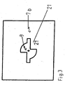
- the pictures Fig. 1 to Fig. 5 show the cross section of the coupling system according to the invention.
- the one connecting element 7a is plate-shaped or part of a plate 22. At the two ends of a connecting element 7a holding portions 26 are formed. Each holding section 26 comprises a head section 1, a connecting section 1a, a section 5 and a base section 6. The base section 6 merges into the section 5, which tapers in the direction of the free end 98. The base portion 6 can pass in a further embodiment without section 5 in the connecting portion 1a.
- the section 5 merges into the connecting section 1 a, which continues as the head section 1.
- the head portion 1 forms, with the connecting portion 1a and the portion 5, the two opposing engaging portions 4.
- the engaging portions 4 are slit-shaped.
- the plate-shaped edge arcs 10, 15 of the holding region 19 of the other connecting element 7b engage in the engagement regions 4.
- the engagement region 4 is bounded laterally by the region 27 of the head section 1 and the edge region 2 of the section 5 as well as by the base edge 3 arranged between the region 27 and the edge region 2.
- the engagement region 4 is open to one side.
- the base edge 3 merges into the edge region 2 of the section 5 or of the base section 6 to form a recess groove 8.
- the Einstülpnut 8 is aligned perpendicular to the longitudinal center axis M of a connecting element 7a.
- the one connecting element 7a is integrally formed with its two holding portions 26 or at least with a holding portion 26.
- the other connecting element 7 b is part of a plate with an opening 9, which is milled out of the plate 22.
- the opening 9 comprises a lead-through area 18 and a holding area 19.
- the lead-through area 18 merges at least partially into a hollow-cylindrical extended holding area 19.
- the lead-through region 18 is rectangular in plan view and is adapted to the holding section 26.
- the passage area 18 allows the passage of the holding portion 26 with its head portion 1 along the center longitudinal axis A of the lead-through area.
- the holding region 19 is hollow cylindrical, in which protrude inwards 31, 32. The indentations can be brought to coincide by a plane rotation, preferably of 180 °, about the cylinder axis A of the holding region 19.
- the connecting portion 1 a of the holding portion 26 pivoted into the holding area 19 can not be pivoted further counterclockwise by the indentations 31, 32, but can only be pivoted back into the lead-through area 18 in the opposite direction, the direction of rotation of the holding portion 26 is determined by FIG Indentations 31, 32 limited.
- the connecting portion 1 a of the holding portion 26 which is pivoted into the holding area 19 as far as the stop the connection provided by the sufficient clamping fit of both connecting elements 7 a, 7 b is provided.
- the pivot axis or rotation axis of the holding region 19 coincides with the center longitudinal axis M of the one connecting element 7a and with the cylinder axis and the center longitudinal axis A of the lead-through region 18 of the holding region 19.
- the lead-through area 18 also has opposite side walls. The opposite offset to each other side walls 12 with 16 and 11 with 17 and 13 with 14 correspond in length.
- the lead-through region 18 has a center longitudinal axis A. Along the center longitudinal axis A, the holding section 26 is passed, so that the marginal arches 10 and 15 are arranged at the level of the engagement areas and the head section 1 is outside the lead-through area.
- the holding portion 19 is circular arc in plan view.
- the holding area 19 is bez. its interior cylindrical and has a center longitudinal axis A, which may correspond to its cylinder axis A.
- the holding area 19 is also limited in plan view by two approximately quarter-circle-arcuate marginal arcs 10, 15.
- the quadrant arcs of the marginal arcs 10 and 15 correspond to each other.
- In the holding area 19 engage two indentations 31, 32 a.
- the two recesses 31, 32 which are offset from one another can be aligned symmetrically with respect to the cylinder axis A or center longitudinal axis A, or they can be aligned with each other center-symmetrically.
- the cylinder axis A coincides with the center longitudinal axis A of the holding region 19 or that of the lead-through region 18.
- the first indentation 31 has a first edge region 12, which continues as a side wall of the lead-through region 18.
- the first edge region 12 is opposite to a second edge region 11.
- the second edge region 11 is aligned parallel to the first edge region 12.
- the first edge region 12 is longer than the second edge region 11.
- the second indentation 32 likewise has a third edge region 16, which continues as a side wall of the leadthrough region 18.
- Opposite the third edge region 16 is a fourth edge region 17, which is aligned parallel to the third edge region 16.
- the fourth edge region 17 has the same length in plan view as the second edge region 11, and the first edge region 12 has the same length in plan view like the third edge area 16.
- the opening comprises the lead-through area 18 and the holding area 19 and is laterally delimited in plan view.
- the interior 41 of the opening 9 of the other connecting part 7b is also delimited by the first to the sixth edge regions 11, 12, 14, 17, 16, 13, formed as side walls, by the edge arches 15, 10 and by the side regions 80 formed as side walls.
- the opening 9 is not open in the plan view laterally.
- the distance A1 between the third edge region 16 and the fourth edge region 17 or between the first edge region 12 and the second edge region 11 corresponds approximately to the thickness or plate thickness of the holding section 26 of the one connecting element 7a.
- the distance A1 may be slightly greater than the plate thickness to facilitate the passage of the holding portion 26 with its head portion 1 through the lead-through area 18 and to avoid tilting.
- the first, the second, third and fourth edge regions are aligned in the plane parallel to the plate and the fifth and the sixth transversely to the longitudinal extent of the lead-through area; the marginal arcs are approximately quarter-circular arc-shaped.
- B2 can also be slightly smaller than D3 to avoid jamming or jamming. Therefore, reference may be made to terms such as "about”, “substantially” when indicating other dimensions and proportions.
- the distance A2 and the distance A1 may coincide with each other and the plate thickness of the holding portion 26 of the plate-shaped one connecting element 7a correspond.
- the holding portion 19 is also characterized both by the two opposite, offset from each other or spaced-apart indentations 31, 32 as well as by the two quarter-circular arc-shaped opposite edge sheets 10, 15; the holding area 19 is supported by its side walls, e.g. from the sixth edge region 13, the fifth edge region, the first edge bend 10 and the second edge bend of the holding region 19.
- the holding region 19 is formed in the plan view of the plate plane at least partially circular, its circle center or cylinder axis A coincides with the center longitudinal axis A of the passage opening 18.
- the holding portion 26 is guided with its head portion 1 through the lead-through area 18, so that the engagement area 4 in height of the plate-shaped indentations 31, 32 is located.
- the other connecting element 7b is also plate-shaped.
- the holding portion 26 is pivoted in the direction of indentations 31, 32 (see arrow) counterclockwise and lies down with its connecting portion 1a to the fifth edge portion 14 and to the sixth edge portion 13 of the two indentations 31, 32 of the holding portion 19 at.
- the two opposite engagement regions 4 receive the two plate-shaped circular arc-shaped edge arches 10, 15, so that each edge arc with the head portion 1 and the region 27 on the one and with the portion 5 and the edge region 2 on the other side in the pivoted state form fit is encompassed, so that a connection caused by a clamping fit between the two connecting elements is made possible.
- the connection is supported by force and friction.
- the base edge 3 of the connecting portion 1a abuts against the side walls 61 of the edge sheets 10, 15.
- the pivoting of the holding portion 26 in the holding area 19 about the center longitudinal axis A is the inward indentations 31, 32 and their fifth and sixth edge areas 14, 13 limited and the angle is 90 °.
- the holding portion 26 in the pivoted state is in transverse position to the other connecting part 7b.
- the one connecting element 7a can not be moved out of the holding region 19 along the center longitudinal axis A, because the marginal arches 10, 15 are firmly engaged in the engaging regions 4.
- the holding section 26, which is swiveled in the holding area 19, allows the fixed location of the connecting elements 7a, 7b coupled to one another.
- connection system according to the invention in the pivoted state not only allows a sufficient positive engagement of the two connecting elements 7a, 7b each other, but also a force and friction.
- the forces on the one Load fastener 7a are transferred to the other connecting element 7b and vice versa, without it occur in certain areas of the coupled furniture parts to deformations, form instabilities or even unintentional release of the interconnected fasteners.
- the side parts 92 designed as supports with the opening 9 of the other connecting element 7b.
- the seat surface or plate 93 as a support is formed with the holding portion 26 of the one connecting member 7a.
- the furniture according to the invention show that the openings 19 in contrast to the recesses conventional Connection systems can be arranged not only in the lateral edge regions of the furniture parts, but rather it may be the convenience and the desire of the user to decide in which places breakthroughs are arranged as another connection element.
- An inventive piece of seating furniture comprises with supports and carriers, wherein the supports 92 and support 93 are detachably connected as furniture parts by the coupling systems according to the invention.
- the supports 92 and support 93 are aligned perpendicular to each other.
- the one connecting elements 7a are integrally formed with the holding portions and the supports 92 have the openings 9 of the other connecting elements 7b, in which the holding portions 26 are receivable to provide the respective connections.
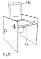
- a carrier 93a is designed as a seat plate and another carrier is designed as a back plate 93a as furniture parts.
- the one connecting element 7a with the holding portions 26 for cooperation with the openings 9 of the other connecting elements 7b of the supports 92 is formed.
- At least one recess 95 which is arranged at the height of the seat plate 93, is milled out of the back plate 93a.
- the seat plate 93 tapers in its region facing the back plate 93a, so that it is formed into a tongue section 96.
- the tongue portion protrudes into the recess 95 of the back plate 93a or is at least partially passed through the recess 95 in another embodiment.
- the tongue portion 96 is centered in the recess 95 of the back plate 93a.
- the front part 96a of the tongue portion 96 guided out of the recess 95 is secured without tools by means of a pin inserted into a cut-out milled in the front part 96a.
- the assembly of the seat piece of furniture according to the invention is carried out in a simple and rapid manner without the aid of tools or other aids, by inserting the holding portions 26 of the back plate 93a in the lead-through areas 18 of the openings 9 of the side parts 92 and transferring the holding portions 26 in the pivoted state by folding up the back plate 93a, so that the holding portions 26a in the holding portions 19 until it stops against the indentations 31, 32 or at the edge regions 13, 15 of the indentations 31, 32 are pivoted in the pivoted state, Inserting the holding portions 26 of the seat plate 93 in the openings 9 of the side parts 92 and Transferring the holding portions 26 of the seat plate 93 in the pivoted state by pivoting down the seat plate 93 with insertion of the tongue portion 96 in the recess 95 of the back plate 93 a, so that the holding portions 26a are pivoted into the holding regions 19 until they abut against the indentations 31, 32 or against the edge regions 13, 15 of the indentations 31, 32 in the pivoted
- the flexibility of assembling the piece of seating furniture according to the invention is also evident in that the steps for assembling can be changed as follows in a further embodiment by inserting the holding portions 26 of the back plate 93a in the lead-through areas 18 of the openings 9 of the side parts 92 and after slightly folding up the same insertion of the holding portions 26 of the seat plate 93 in the openings 9 of the side parts 92, Conversion of the holding portions 26 of the back plate 93a in the pivoted state by folding up the back plate 93a, so that the holding portions 26a in the holding portions 19 until it stops against the indentations 31, 32 and to the edge regions 13, 15 of the indentations 31, 32 in the tilted state to be panned, Transferring the holding portions 26 of the seat plate 93 in the pivoted state by pivoting down the seat plate 93 with insertion of the tongue portion 96 in the recess 95 of the back plate 93 a, so that the holding portions 26a are pivoted into the holding regions 19 until they abut against the indentations
- the tongue portion 96 located in the recess 95 allows increased stability and seat safety of the seat piece of furniture according to the invention even with increased seat load thereof by a user.
- the dimensional stability of the seating furniture piece according to the invention is considerably increased by the tongue portion arranged in the recess, because the springback of the seat plate in the direction of footing due to high, acting on the seat plate forces is limited by the rest of the tongue portion on the lower side of the recess.
- the insertion area which is open towards one side and the orientation of the recess which is arranged laterally as possible in a furniture part is not required.
- the furniture parts coupled to the furniture by means of the coupling system according to the invention do not restrict the overall aesthetic impression, but even promote it and contribute to the balance in appearance, statics and expediency.
- furniture and parts thereof any materials such as wood, stone-like materials, ceramics and / or plastic-like materials and mixtures thereof.
- the furniture according to the invention can be quickly and easily decoupled or dismounted and inexpensively transported.
- furniture parts of the disassembled furniture of the invention require little space in their storage and are characterized by a certain robustness during storage.
- the furniture according to the invention are insensitive to damage provide a rapid assembly of furniture.
- the seat piece of furniture according to the invention is characterized by a stability and seat safety as well -by a high load capacity and sufficient durability of the connections by a sufficient durability of the furniture parts and their fasteners as well as its assembly and its degradation are distinguished through a little time-consuming construction without the aid of tools and other aids such as through very low demands on the skill of the user, and smallest footprint of the furniture parts during storage advantageously from.
Landscapes
- Engineering & Computer Science (AREA)
- General Engineering & Computer Science (AREA)
- Mechanical Engineering (AREA)
- Life Sciences & Earth Sciences (AREA)
- Wood Science & Technology (AREA)
- Connection Of Plates (AREA)
- Furniture Connections (AREA)
- Telephone Set Structure (AREA)
- Cabinets, Racks, Or The Like Of Rigid Construction (AREA)
- Combinations Of Kitchen Furniture (AREA)
Claims (31)
- Système de couplage pour assembler des éléments de meuble de manière à pouvoir les désolidariser à nouveau, ledit système de couplage comportant deux éléments d'assemblage (7a, 7b) en forme de plaque,a. les éléments d'assemblage (7a, 7b) étant réalisés de manière déplaçable l'un par rapport à l'autre, et au moins un assemblage pouvant à nouveau être désolidarisé est réalisable entre les éléments de meuble, l'autre des éléments d'assemblage (7b), comportant un trou débouchant (9), qui peut équiper un premier élément du meuble et l'un des éléments d'assemblage (7a) est une partie de fixation (26), propre à être agencée sur un deuxième élément de meuble et apte être amenée en prise avec le trou débouchant (9),b. la partie de fixation (26) de l'un des éléments d'assemblage (7a) possède une partie de base (6), une partie (5) adjacente à la partie de base (6), et une partie de liaison (1a) en forme de traverse, qui est adjacente à la partie (5) et qui se prolonge au niveau de l'extrémité libre de la partie de fixation (26) par une partie de tête (1) dégagée,c. la partie de tête (1) comporte au moins une zone dégagée (27) qui forme, avec une zone de bordure (2), de la partie (5) située à distance de la zone dégagée (27), des zones de prise (4) pour l'autre des éléments d'assemblage (7b), au moins deux zones de prise (4), ouvertes en sens opposé, étant réalisées sur la partie de fixation (26),d. les zones de prise (4) sont délimitées vers la partie de liaison (1a) par un bord de base (3),
caractérisé en ce quee. la partie (5), en vue de dessus, se rétrécit vers l'extrémité libre de la partie de fixation (26),f. une zone de transition, entre le bord de base (3) et la zone de bordure (2) de la partie (5), est restreinte en formant une rainure pénétrante (8),
etg. la rainure pénétrante (8) est orientée transversalement à un axe médian longitudinal M de l'un des éléments d'assemblage (7a),h. le trou débouchant (9) est délimité sur tous les côtés dans la vue de dessus, comporte une zone de passage (18), pour faire passer la partie de fixation (26) de l'un des éléments d'assemblage (7a) avec sa partie de tête (1) le long de l'axe médian longitudinal A de la zone de passage (18), et une zone de retenue (19) pour recevoir la partie de fixation (26) de l'un des éléments d'assemblage (7a) dans la position pivotée,i. la zone de passage (18) est rectangulaire en vue de dessus et se prolonge de manière centrée par la zone de retenue (19) élargie en forme de cylindre creux, dans laquelle s'engagent des enfoncements (31, 32) qui sont disposés face à face et à distance l'un de l'autre,j. la partie de fixation (26), dans la position pivotée, vient buter avec sa partie de liaison (1a) contre les enfoncements (31, 32). - Système de couplage selon la revendication 1, caractérisé en ce que
le pivotement de la partie de fixation (26), passée à travers la zone de passage le long de l'axe médian longitudinal A de celle-ci, dans la zone de retenue (19) depuis la position introduite vers la position pivotée dans une direction vers les enfoncements (31, 32) autour de l'axe médian longitudinal A, est limité par les enfoncements (31, 32) et leur cinquième zone de bordure (14) et leur sixième zone de bordure (13), et
la partie de liaison (1a) de la partie de fixation (26) est pivotée dans la zone de retenue (19) à travers les enfoncements (31, 32) jusqu'à la butée, l'un des éléments d'assemblage (7a) avec sa partie de fixation (26) dans la position pivotée est bloquée en position transversale par rapport à l'autre des éléments d'assemblage (7b), la zone (27) de la partie de tête (1) et les zones de bordure (2) de la partie (5), ainsi que les bords de base (3) de la partie de liaison (1a) sont en appui contre les trois côtés des arcs de bordure (10, 15) de l'autre des éléments d'assemblage (7b) et entourent ceux-ci pour réaliser un assemblage par complémentarité de forme, un assemblage par frottement et/ou un assemblage par adhérence. - Système de couplage selon la revendication 1 ou 2, caractérisé en ce que le pivotement de la partie de fixation (26) dans la zone de retenue (19), à partir de la position introduite vers la position pivotée, s'effectue autour de l'axe médian longitudinal A de la zone de passage (18).
- Système de couplage selon l'une quelconque des revendications 1 à 3, caractérisé en ce que pour le mouvement de retour de l'un des éléments d'assemblage (7a) avec sa partie de fixation (26) le long de l'axe médian longitudinal A, la partie de fixation (26) de l'un des éléments d'assemblage (7a), située en position transversale par rapport à l'autre des éléments d'assemblage (7b), pivote en retour dans la zone de passage (18) autour de l'axe médian longitudinal A, hors de la position transversale ou hors de la position pivotée vers la position introduite.
- Système de couplage selon l'une quelconque des revendications 1 à 4, caractérisé en ce qu'une largeur B3 de la partie (5) et/ou une largeur B4 de la partie de base (6) sont supérieures à une largeur B1 de la partie de tête (1).
- Système de couplage selon l'une quelconque des revendications 1 à 5, caractérisé en ce que la largeur B3 de la partie (5) est 1,2 fois à 2,0 fois plus grande que la largeur B1 de la partie de tête (1).
- Système de couplage selon l'une quelconque des revendications 1 à 6, caractérisé en ce qu'une largeur B4 de la partie de base (6) est supérieure à la largeur B3 de la partie (5).
- Système de couplage selon l'une quelconque des revendications 1 à 7, caractérisé en ce que la zone de retenue (19) comporte deux enfoncements (31, 32) disposés symétriquement à son axe de cylindre A, lesdits enfoncements (31, 32) sont situés à distance l'un de l'autre et sont agencés de manière à faire saillie dans un espace intérieur (41) en forme de cylindre creux de la zone de retenue (19).
- Système de couplage selon l'une quelconque des revendications 5 à 8, caractérisé en ce qu'un diamètre D3 de la zone de retenue (19) est inférieur à la largeur B3 de la partie (5).
- Système de couplage selon la revendication 8 ou 9, caractérisé en ce que la partie de fixation (26) de l'un des éléments d'assemblage (7a) est guidée à travers la zone de passage (18) de telle sorte que la partie de fixation (26), ayant traversé ladite zone, est apte à pivoter, hors de sa position introduite dans une position pivotée, par rapport à son axe médian longitudinal M au moins selon un angle prédéfini, en particulier de 90°, la partie de fixation (26), dans la position pivotée, ne pouvant pas être ramenée hors de la zone de retenue (19) le long de l'axe du cylindre A de la zone de retenue (19).
- Système de couplage selon l'une quelconque des revendications 1 à 10, caractérisé en ce que la partie de liaison (1a), pivotée dans la zone de retenue (19) jusqu'à la butée, est apte, dans la position pivotée, à pivoter de manière limitée par les enfoncements (31, 32) seulement dans un sens de rotation.
- Système de couplage selon l'une quelconque des revendications 1 à 11, caractérisé en ce que dans la position pivotée, la partie de liaison (1a) est en appui contre une cinquième zone de bordure (14) et une sixième zone de bordure (13) de la zone de retenue (19), et l'axe médian longitudinal M coïncide, dans la position pivotée, avec l'axe du cylindre A et/ou l'axe médian longitudinal A de la zone de passage (18) de la zone de retenue (19).
- Système de couplage selon l'une quelconque des revendications 1 à 12, caractérisé en ce que le premier enfoncement (31) comporte une première zone de bordure (12) et une cinquième zone de bordure (14), la cinquième zone de bordure (14) est orientée perpendiculairement à la première zone de bordure (12), une deuxième zone de bordure (11) est située en face de la première zone de bordure (12), la deuxième zone de bordure (11) se prolonge par un premier arc de bordure (10) courbe, le premier arc de bordure (10) s'étend autour de l'axe du cylindre A, le premier arc de bordure (10) se prolonge par une sixième zone de bordure (13), la sixième zone de bordure (13) se prolonge par une troisième zone de bordure (16) orientée perpendiculairement à celle-ci, la troisième zone de bordure s'étend parallèlement à la première zone de bordure (12), en face de la troisième zone de bordure (16) est disposée une quatrième zone de bordure (17), qui se prolonge par un deuxième arc de bordure (15) courbe, la quatrième zone de bordure (17) est orientée parallèlement à la deuxième zone de bordure (11), lequel deuxième arc de bordure (15) s'étend autour de l'axe du cylindre A, le deuxième arc de bordure (15) se prolonge par la cinquième zone de bordure (14) qui est orientée parallèlement à la sixième zone de bordure (13), les première (12), deuxième (11), troisième (16) et quatrième (17) zones de bordure sont réalisées sous forme de parois latérales de la zone de passage (18), laquelle zone de passage (18) est délimitée latéralement par des zones latérales formant des parois latérales (80), orientées perpendiculairement à la première zone de bordure (12), sachant que l'une des parois latérales (80) relie la première zone de bordure (12) à la deuxième zone de bordure (11) et l'autre paroi latérale (80) relie la troisième zone de bordure (16) à la quatrième zone de bordure (17).
- Système de couplage selon l'une quelconque des revendications 1 à 13, caractérisé en ce que la première zone de bordure (12), la troisième zone de bordure (16), la deuxième zone de bordure (11) et/ou la quatrième zone de bordure (17) sont disposées de manière planes et parallèles entre elles.
- Système de couplage selon l'une quelconque des revendications 1 à 14, caractérisé en ce que les arcs de bordure (10, 15) sont réalisés en forme de quart de cercle.
- Système de couplage selon l'une quelconque des revendications 1 à 15, caractérisé en ce que en vue de dessus, le trou débouchant (9) de l'autre des éléments d'assemblage (7b) est délimité latéralement par la première jusqu'à la sixième zone de bordure (12, 11, 16, 17, 14, 13), par les arcs de bordure (10, 15) et par les parois latérales (80).
- Système de couplage selon l'une quelconque des revendications 1 à 16, caractérisé en ce que le diamètre D3 de la zone de retenue (19) est inférieur au diamètre D2 de la zone de passage (18).
- Système de couplage selon l'une quelconque des revendications 1 à 17, caractérisé en ce que le diamètre D3 de la zone de retenue (19) correspond à la largeur B2 de la partie de liaison (1a).
- Système de couplage selon l'une quelconque des revendications 1 à 18, caractérisé en ce que la longueur A4 de la deuxième zone de bordure (11) et/ou la longueur A4 de la quatrième zone de bordure (17) correspondent à la distance A6 de la zone de prise (4).
- Système de couplage selon l'une quelconque des revendications 1 à 19, caractérisé en ce que l'épaisseur des arcs de bordure (10, 15) correspond à la distance A5 entre la zone de bordure (2) de la partie (5) et la zone (27) de la partie de tête (1).
- Système de couplage selon l'une quelconque des revendications 1 à 20, caractérisé en ce que les zones de prise (4) sont réalisées en forme de fente.
- Système de couplage selon l'une quelconque des revendications 1 à 21, caractérisé en ce que l'un des éléments d'assemblage est réalisé d'un seul tenant.
- Système de couplage selon l'une quelconque des revendications 1 à 22, caractérisé en ce que l'autre des éléments d'assemblage est réalisé d'un seul tenant.
- Meubles, qui comportent, comme éléments de meuble, des appuis, supports et/ou autres éléments, en particulier des dossiers, les appuis (92), les supports (93) et/ou les autres éléments de meubles étant assemblés entre eux de manière à pouvoir les désolidariser par le système de couplage selon l'une quelconque des revendications précédentes.
- Meubles selon la revendication 24, caractérisés en ce que les éléments des meubles sont réalisés sous la forme de plaques.
- Meubles selon la revendication 24 ou 25, caractérisés en ce que les appuis (92) et/ou les supports (93) sont réalisés avec les éléments d'assemblage (7a, 7b),
les éléments d'assemblage (7a, 7b) sont réalisés de manière déplaçable l'un par rapport à l'autre, et au moins un assemblage pouvant à nouveau être désolidarisé peut être réalisé entre les éléments de meuble, l'autre des éléments d'assemblage (7b) comporte un trou débouchant (9) dans un premier élément de meuble et l'un des éléments d'assemblage (7a) est une partie de fixation (26), agencée sur un deuxième élément de meuble et apte à être amenée en prise avec le trou débouchant (9),
la partie de fixation (26) de l'un des éléments d'assemblage (7a) possède une partie de base (6), une partie (5) adjacente à la partie de base (6), et une partie de liaison (1a) en forme de traverse, qui est adjacente à la partie (5) et qui se prolonge au niveau de l'extrémité libre de la partie de fixation (26) par une partie de tête (1) dégagée,
la partie de tête (1) comporte au moins une zone dégagée (27) qui, avec une zone de bordure (2), située à distance de la zone dégagée (27), de la partie (5), forme une zone de prise (4) pour l'autre des éléments d'assemblage (7b), au moins deux zones de prise (4), ouvertes en sens opposé, sont réalisées sur la partie de fixation (26),
les zones de prise (4) sont délimitées vers la partie de liaison (1a) par un bord de base (3),
la partie (5), en vue de dessus, se rétrécit vers l'extrémité libre de la partie de fixation (26),
une zone de transition, entre le bord de base (3) et la zone de bordure (2) de la partie (5), est restreinte en formant une rainure pénétrante (8),
et
la rainure pénétrante (8) est orientée transversalement à un axe médian longitudinal M de l'un des éléments d'assemblage (7a),
le trou débouchant (9), délimité latéralement, de l'autre des éléments d'assemblage (7b) comporte une zone de passage (18) de forme rectangulaire en vue de dessus, qui se prolonge de manière centrée par une zone de retenue (19) élargie en forme de cylindre creux, la zone de retenue (19) comporte deux enfoncements (31, 32), disposés symétriquement par rapport à son axe de cylindre A, les enfoncements (31, 32) sont situés à distance l'un de l'autre et sont disposés en faisant saillie dans un espace intérieur (41) cylindrique creux de la zone de retenue (19),
la partie de fixation (26) de l'un des éléments d'assemblage (7a) est passé à travers la zone de passage (18), de telle sorte que la partie de fixation (26), ayant passé à travers ladite zone, est apte à pivoter, hors de sa position introduite dans une position pivotée, par rapport à son axe médian longitudinal M au moins selon un angle prédéfini, en particulier de 90°, la partie de fixation (26), dans la position pivotée, vient buter avec sa partie de liaison (1a) contre les enfoncements (31, 32) et ne peut pas être ramenée hors de la zone de retenue (19) le long de l'axe du cylindre A de la zone de retenue (19),
et
la partie de liaison (1a), pivotée dans la zone de retenue (19) jusqu'à la butée, est apte, dans la position pivotée, à pivoter de manière limitée par les enfoncements (31, 32) seulement dans un sens de rotation. - Siège avec des appuis (92) et des supports (93), caractérisé en ce que les appuis (92) et les supports (93) formant des éléments du meuble sont assemblés de manière à pouvoir les désolidariser par l'intermédiaire d'au moins un système de couplage selon l'une quelconque des revendications 1 à 23.
- Siège selon la revendication 27, caractérisé en ce que les unes des éléments d'assemblage (7a) avec les parties de fixation (26) sont formés sur les supports (93) formant le deuxième élément du meuble,
et
les appuis (92) formant le premier élément du meuble comportent les trous débouchants (9) des autres des éléments d'assemblage (7b), lesquels sont propres à recevoir les parties de fixation (26) pour réaliser les assemblages respectifs. - Siège selon la revendication 28, caractérisé en ce que
un support (93) est réalisé sous la forme d'un plateau d'assise,
le siège comporte un plateau de dossier (93a) formant un élément du meuble, sur lequel sont formés les uns des éléments d'assemblage (7a) formant le deuxième élément du meuble, avec les parties de fixation pour coopérer avec les trous débouchants (9) des autres des éléments d'assemblage (7b),
le plateau de dossier (93a) comporte au moins un évidement (95) qui est situé à hauteur du plateau d'assise (93) dans la position non sollicitée, le plateau d'assise (93) se rétrécit dans sa zone orientée vers le plateau de dossier (93a) et forme au moins une languette (96) qui fait saillie dans l'évidement (95) du plateau de dossier (93a) ou est guidé au moins partiellement à travers l'évidement (95), de préférence la languette (96) est agencée de manière centrée dans l'évidement du plateau de dossier. - Siège selon la revendication 29, caractérisé en ce qu'une partie avant (96a) de la patte (96), guidée hors de l'évidement (95) est immobilisée sans outil avec une goupille introduite dans un trou débouchant fraisé dans la partie avant (96a).
- Siège selon la revendication 30, caractérisé en ce que la goupille formant un assemblage par goupille est, en plus, immobilisé de manière à pouvoir le désolidariser par des éléments d'immobilisation.
Applications Claiming Priority (2)
| Application Number | Priority Date | Filing Date | Title |
|---|---|---|---|
| DE102005016998A DE102005016998B4 (de) | 2005-04-13 | 2005-04-13 | Kopplungssystem zum raschen lösbaren Verbinden von Möbelteilen und mit geringem Platzbedarf bei Lagerung |
| PCT/DE2006/000719 WO2006108415A1 (fr) | 2005-04-13 | 2006-04-12 | Systeme d'accouplement pour assemblage amovible rapide de parties de meubles, a faible encombrement au stockage, et sieges |
Publications (2)
| Publication Number | Publication Date |
|---|---|
| EP1869331A1 EP1869331A1 (fr) | 2007-12-26 |
| EP1869331B1 true EP1869331B1 (fr) | 2010-02-24 |
Family
ID=36694203
Family Applications (1)
| Application Number | Title | Priority Date | Filing Date |
|---|---|---|---|
| EP06742262A Not-in-force EP1869331B1 (fr) | 2005-04-13 | 2006-04-12 | Systeme d'accouplement pour assemblage amovible rapide de parties de meubles, a faible encombrement au stockage, et sieges |
Country Status (4)
| Country | Link |
|---|---|
| EP (1) | EP1869331B1 (fr) |
| AT (1) | ATE458915T1 (fr) |
| DE (4) | DE102005016998B4 (fr) |
| WO (1) | WO2006108415A1 (fr) |
Cited By (1)
| Publication number | Priority date | Publication date | Assignee | Title |
|---|---|---|---|---|
| DE202014104925U1 (de) * | 2014-10-16 | 2016-01-19 | Grass Gmbh | Verbindungsvorrichtung |
Families Citing this family (5)
| Publication number | Priority date | Publication date | Assignee | Title |
|---|---|---|---|---|
| SE1150145A1 (sv) * | 2011-02-22 | 2012-02-28 | Hl Display Ab | Hyllanordning |
| DE102014101997A1 (de) | 2014-02-18 | 2015-08-20 | Karl Storz Gmbh & Co. Kg | Gerätewagen |
| CN104963922A (zh) * | 2015-06-08 | 2015-10-07 | 湖州美胜机械有限公司 | 一种座椅组装用连接装置 |
| CN106901531B (zh) * | 2017-04-15 | 2019-11-29 | 诸暨易和项目投资有限公司 | 一种教室用可调节翻转座椅 |
| CN114893478A (zh) * | 2022-02-17 | 2022-08-12 | 成都新骏装饰材料有限公司 | 一种单边连接件及铝合金薄板柜 |
Family Cites Families (7)
| Publication number | Priority date | Publication date | Assignee | Title |
|---|---|---|---|---|
| CH483819A (de) * | 1967-12-23 | 1970-01-15 | Efka Werke Kiehn Gmbh Fritz | Knotenelement |
| US4657462A (en) * | 1985-08-08 | 1987-04-14 | Simmons Fastener Corporation | Quarter-turn fastener |
| DE29610533U1 (de) * | 1996-06-15 | 1996-08-29 | Wilhelm Hardeweg GmbH, 46342 Velen | Verbindungssystem zum Verbinden von Möbelteilen |
| GB2323652B (en) * | 1997-03-26 | 2000-12-20 | Miles Roland William Bozeat | Means of assembly |
| DE29902857U1 (de) * | 1999-02-18 | 1999-09-02 | Nähring, Ralf, Dipl.-Designer, 48477 Hörstel | Verbindung von horizontalen und vertikalen Plattenwerkstoffen beliebiger Größe, die bei Bedarf wieder lösbar sind |
| DE10327775A1 (de) * | 2003-06-20 | 2005-01-05 | Hellmich, Stefan | Möbelverbindung |
| DE202005005807U1 (de) * | 2005-04-07 | 2005-09-08 | REISS Büromöbel GmbH | Möbel |
-
2005
- 2005-04-13 DE DE102005016998A patent/DE102005016998B4/de not_active Expired - Fee Related
-
2006
- 2006-04-12 AT AT06742262T patent/ATE458915T1/de active
- 2006-04-12 DE DE502006006242T patent/DE502006006242D1/de active Active
- 2006-04-12 WO PCT/DE2006/000719 patent/WO2006108415A1/fr not_active Ceased
- 2006-04-12 DE DE202006006146U patent/DE202006006146U1/de not_active Expired - Lifetime
- 2006-04-12 DE DE112006001566T patent/DE112006001566A5/de not_active Withdrawn
- 2006-04-12 EP EP06742262A patent/EP1869331B1/fr not_active Not-in-force
Cited By (1)
| Publication number | Priority date | Publication date | Assignee | Title |
|---|---|---|---|---|
| DE202014104925U1 (de) * | 2014-10-16 | 2016-01-19 | Grass Gmbh | Verbindungsvorrichtung |
Also Published As
| Publication number | Publication date |
|---|---|
| DE202006006146U1 (de) | 2006-10-05 |
| EP1869331A1 (fr) | 2007-12-26 |
| DE502006006242D1 (de) | 2010-04-08 |
| ATE458915T1 (de) | 2010-03-15 |
| DE112006001566A5 (de) | 2008-03-27 |
| DE102005016998A1 (de) | 2006-10-19 |
| WO2006108415A1 (fr) | 2006-10-19 |
| DE102005016998B4 (de) | 2007-11-15 |
Similar Documents
| Publication | Publication Date | Title |
|---|---|---|
| EP3862510B1 (fr) | Support de compensation | |
| DE202015009438U1 (de) | Eckverbinder für stabförmige Profilelemente | |
| EP0099972B1 (fr) | Elément d'assemblage pour plaques | |
| EP1869331B1 (fr) | Systeme d'accouplement pour assemblage amovible rapide de parties de meubles, a faible encombrement au stockage, et sieges | |
| DE69210796T3 (de) | Klammer, insbesondere zur Befestigung von Heizkörpern | |
| EP2014171B1 (fr) | Plateau de cuisson | |
| EP0287981A2 (fr) | Connecteur pour le raccordement de deux éléments | |
| DE202005002790U1 (de) | Bausatz zur Verbindung von Trägerelementen | |
| EP1257185A1 (fr) | Element de raccordement pour un meuble, notamment pour une table | |
| DE3121265C2 (de) | Kleinmöbel mit stufenlos neigbarer Platte, insbesondere zur Verwendung als Hocker | |
| AT11947U1 (de) | Zerleg- und zusammensetzbares möbel mit feder-nut-verbindung | |
| DE3317190A1 (de) | Kreuzkupplung | |
| DE4406212C2 (de) | Tragsystem mit Tragprofilen für Messestandsysteme, Stellwände, Möbel oder dgl. | |
| WO2000021418A2 (fr) | Assemblage enfichable pour systeme de presentation | |
| DE60003658T2 (de) | Spannvorrichtung | |
| DE3119817C2 (de) | Klemmelement | |
| DE102012200315A1 (de) | Montagerahmen zum Einbau eines Kochfelds | |
| DE29610533U1 (de) | Verbindungssystem zum Verbinden von Möbelteilen | |
| EP1420211A2 (fr) | Dispositif de suppor mural d'un radiateur | |
| DE19920447C2 (de) | Gestellsystem | |
| DE2752580A1 (de) | Befestigungsvorrichtung fuer tablars und haengeschraenke | |
| DE1654655C3 (de) | Lagergestell | |
| DE202023102174U1 (de) | Haltevorrichtung zur Anbringung eines Einsatzteils an einem Regalpfosten sowie Regalpfosten zur Anbringung eines Einsatzteils an diesem | |
| AT508987B1 (de) | Regal mit einem bodenteil und zumindest einem seitenteil | |
| AT11949U1 (de) | Werkzeuglos zerleg- und zusammensetzbares möbel |
Legal Events
| Date | Code | Title | Description |
|---|---|---|---|
| PUAI | Public reference made under article 153(3) epc to a published international application that has entered the european phase |
Free format text: ORIGINAL CODE: 0009012 |
|
| 17P | Request for examination filed |
Effective date: 20071018 |
|
| AK | Designated contracting states |
Kind code of ref document: A1 Designated state(s): AT BE BG CH CY CZ DE DK EE ES FI FR GB GR HU IE IS IT LI LT LU LV MC NL PL PT RO SE SI SK TR |
|
| 17Q | First examination report despatched |
Effective date: 20080509 |
|
| DAX | Request for extension of the european patent (deleted) | ||
| GRAP | Despatch of communication of intention to grant a patent |
Free format text: ORIGINAL CODE: EPIDOSNIGR1 |
|
| GRAS | Grant fee paid |
Free format text: ORIGINAL CODE: EPIDOSNIGR3 |
|
| GRAA | (expected) grant |
Free format text: ORIGINAL CODE: 0009210 |
|
| AK | Designated contracting states |
Kind code of ref document: B1 Designated state(s): AT BE BG CH CY CZ DE DK EE ES FI FR GB GR HU IE IS IT LI LT LU LV MC NL PL PT RO SE SI SK TR |
|
| REG | Reference to a national code |
Ref country code: GB Ref legal event code: FG4D Free format text: NOT ENGLISH |
|
| REG | Reference to a national code |
Ref country code: CH Ref legal event code: EP |
|
| REG | Reference to a national code |
Ref country code: IE Ref legal event code: FG4D Free format text: LANGUAGE OF EP DOCUMENT: GERMAN |
|
| REF | Corresponds to: |
Ref document number: 502006006242 Country of ref document: DE Date of ref document: 20100408 Kind code of ref document: P |
|
| REG | Reference to a national code |
Ref country code: NL Ref legal event code: VDEP Effective date: 20100224 |
|
| LTIE | Lt: invalidation of european patent or patent extension |
Effective date: 20100224 |
|
| PG25 | Lapsed in a contracting state [announced via postgrant information from national office to epo] |
Ref country code: IS Free format text: LAPSE BECAUSE OF FAILURE TO SUBMIT A TRANSLATION OF THE DESCRIPTION OR TO PAY THE FEE WITHIN THE PRESCRIBED TIME-LIMIT Effective date: 20100624 Ref country code: PT Free format text: LAPSE BECAUSE OF FAILURE TO SUBMIT A TRANSLATION OF THE DESCRIPTION OR TO PAY THE FEE WITHIN THE PRESCRIBED TIME-LIMIT Effective date: 20100625 Ref country code: LT Free format text: LAPSE BECAUSE OF FAILURE TO SUBMIT A TRANSLATION OF THE DESCRIPTION OR TO PAY THE FEE WITHIN THE PRESCRIBED TIME-LIMIT Effective date: 20100224 |
|
| PG25 | Lapsed in a contracting state [announced via postgrant information from national office to epo] |
Ref country code: PL Free format text: LAPSE BECAUSE OF FAILURE TO SUBMIT A TRANSLATION OF THE DESCRIPTION OR TO PAY THE FEE WITHIN THE PRESCRIBED TIME-LIMIT Effective date: 20100224 Ref country code: SI Free format text: LAPSE BECAUSE OF FAILURE TO SUBMIT A TRANSLATION OF THE DESCRIPTION OR TO PAY THE FEE WITHIN THE PRESCRIBED TIME-LIMIT Effective date: 20100224 Ref country code: LV Free format text: LAPSE BECAUSE OF FAILURE TO SUBMIT A TRANSLATION OF THE DESCRIPTION OR TO PAY THE FEE WITHIN THE PRESCRIBED TIME-LIMIT Effective date: 20100224 Ref country code: FI Free format text: LAPSE BECAUSE OF FAILURE TO SUBMIT A TRANSLATION OF THE DESCRIPTION OR TO PAY THE FEE WITHIN THE PRESCRIBED TIME-LIMIT Effective date: 20100224 |
|
| REG | Reference to a national code |
Ref country code: IE Ref legal event code: FD4D |
|
| PG25 | Lapsed in a contracting state [announced via postgrant information from national office to epo] |
Ref country code: NL Free format text: LAPSE BECAUSE OF FAILURE TO SUBMIT A TRANSLATION OF THE DESCRIPTION OR TO PAY THE FEE WITHIN THE PRESCRIBED TIME-LIMIT Effective date: 20100224 Ref country code: IE Free format text: LAPSE BECAUSE OF FAILURE TO SUBMIT A TRANSLATION OF THE DESCRIPTION OR TO PAY THE FEE WITHIN THE PRESCRIBED TIME-LIMIT Effective date: 20100224 Ref country code: GR Free format text: LAPSE BECAUSE OF FAILURE TO SUBMIT A TRANSLATION OF THE DESCRIPTION OR TO PAY THE FEE WITHIN THE PRESCRIBED TIME-LIMIT Effective date: 20100525 Ref country code: SE Free format text: LAPSE BECAUSE OF FAILURE TO SUBMIT A TRANSLATION OF THE DESCRIPTION OR TO PAY THE FEE WITHIN THE PRESCRIBED TIME-LIMIT Effective date: 20100224 Ref country code: EE Free format text: LAPSE BECAUSE OF FAILURE TO SUBMIT A TRANSLATION OF THE DESCRIPTION OR TO PAY THE FEE WITHIN THE PRESCRIBED TIME-LIMIT Effective date: 20100224 Ref country code: ES Free format text: LAPSE BECAUSE OF FAILURE TO SUBMIT A TRANSLATION OF THE DESCRIPTION OR TO PAY THE FEE WITHIN THE PRESCRIBED TIME-LIMIT Effective date: 20100604 Ref country code: CY Free format text: LAPSE BECAUSE OF FAILURE TO SUBMIT A TRANSLATION OF THE DESCRIPTION OR TO PAY THE FEE WITHIN THE PRESCRIBED TIME-LIMIT Effective date: 20100224 Ref country code: RO Free format text: LAPSE BECAUSE OF FAILURE TO SUBMIT A TRANSLATION OF THE DESCRIPTION OR TO PAY THE FEE WITHIN THE PRESCRIBED TIME-LIMIT Effective date: 20100224 |
|
| BERE | Be: lapsed |
Owner name: WILHELM HARDEWEG G.M.B.H. & CO. KG Effective date: 20100430 |
|
| PG25 | Lapsed in a contracting state [announced via postgrant information from national office to epo] |
Ref country code: MC Free format text: LAPSE BECAUSE OF NON-PAYMENT OF DUE FEES Effective date: 20100430 Ref country code: CZ Free format text: LAPSE BECAUSE OF FAILURE TO SUBMIT A TRANSLATION OF THE DESCRIPTION OR TO PAY THE FEE WITHIN THE PRESCRIBED TIME-LIMIT Effective date: 20100224 Ref country code: BG Free format text: LAPSE BECAUSE OF FAILURE TO SUBMIT A TRANSLATION OF THE DESCRIPTION OR TO PAY THE FEE WITHIN THE PRESCRIBED TIME-LIMIT Effective date: 20100524 Ref country code: SK Free format text: LAPSE BECAUSE OF FAILURE TO SUBMIT A TRANSLATION OF THE DESCRIPTION OR TO PAY THE FEE WITHIN THE PRESCRIBED TIME-LIMIT Effective date: 20100224 |
|
| REG | Reference to a national code |
Ref country code: CH Ref legal event code: PL |
|
| PLBE | No opposition filed within time limit |
Free format text: ORIGINAL CODE: 0009261 |
|
| STAA | Information on the status of an ep patent application or granted ep patent |
Free format text: STATUS: NO OPPOSITION FILED WITHIN TIME LIMIT |
|
| REG | Reference to a national code |
Ref country code: FR Ref legal event code: ST Effective date: 20101230 |
|
| PG25 | Lapsed in a contracting state [announced via postgrant information from national office to epo] |
Ref country code: DK Free format text: LAPSE BECAUSE OF FAILURE TO SUBMIT A TRANSLATION OF THE DESCRIPTION OR TO PAY THE FEE WITHIN THE PRESCRIBED TIME-LIMIT Effective date: 20100224 |
|
| 26N | No opposition filed |
Effective date: 20101125 |
|
| PG25 | Lapsed in a contracting state [announced via postgrant information from national office to epo] |
Ref country code: CH Free format text: LAPSE BECAUSE OF NON-PAYMENT OF DUE FEES Effective date: 20100430 Ref country code: LI Free format text: LAPSE BECAUSE OF NON-PAYMENT OF DUE FEES Effective date: 20100430 |
|
| PG25 | Lapsed in a contracting state [announced via postgrant information from national office to epo] |
Ref country code: IT Free format text: LAPSE BECAUSE OF FAILURE TO SUBMIT A TRANSLATION OF THE DESCRIPTION OR TO PAY THE FEE WITHIN THE PRESCRIBED TIME-LIMIT Effective date: 20100224 Ref country code: BE Free format text: LAPSE BECAUSE OF NON-PAYMENT OF DUE FEES Effective date: 20100430 |
|
| REG | Reference to a national code |
Ref country code: NL Ref legal event code: RD1H Effective date: 20110407 |
|
| REG | Reference to a national code |
Ref country code: NL Ref legal event code: RD2H Effective date: 20110617 |
|
| REG | Reference to a national code |
Ref country code: NL Ref legal event code: T3 |
|
| PGRI | Patent reinstated in contracting state [announced from national office to epo] |
Ref country code: NL Effective date: 20110715 |
|
| PG25 | Lapsed in a contracting state [announced via postgrant information from national office to epo] |
Ref country code: FR Free format text: LAPSE BECAUSE OF NON-PAYMENT OF DUE FEES Effective date: 20100430 |
|
| PG25 | Lapsed in a contracting state [announced via postgrant information from national office to epo] |
Ref country code: LU Free format text: LAPSE BECAUSE OF NON-PAYMENT OF DUE FEES Effective date: 20100412 Ref country code: HU Free format text: LAPSE BECAUSE OF FAILURE TO SUBMIT A TRANSLATION OF THE DESCRIPTION OR TO PAY THE FEE WITHIN THE PRESCRIBED TIME-LIMIT Effective date: 20100825 |
|
| PG25 | Lapsed in a contracting state [announced via postgrant information from national office to epo] |
Ref country code: TR Free format text: LAPSE BECAUSE OF FAILURE TO SUBMIT A TRANSLATION OF THE DESCRIPTION OR TO PAY THE FEE WITHIN THE PRESCRIBED TIME-LIMIT Effective date: 20100224 |
|
| REG | Reference to a national code |
Ref country code: AT Ref legal event code: MM01 Ref document number: 458915 Country of ref document: AT Kind code of ref document: T Effective date: 20110412 |
|
| PG25 | Lapsed in a contracting state [announced via postgrant information from national office to epo] |
Ref country code: AT Free format text: LAPSE BECAUSE OF NON-PAYMENT OF DUE FEES Effective date: 20110412 |
|
| PGFP | Annual fee paid to national office [announced via postgrant information from national office to epo] |
Ref country code: GB Payment date: 20130415 Year of fee payment: 8 |
|
| PGFP | Annual fee paid to national office [announced via postgrant information from national office to epo] |
Ref country code: NL Payment date: 20130412 Year of fee payment: 8 |
|
| REG | Reference to a national code |
Ref country code: NL Ref legal event code: V1 Effective date: 20141101 |
|
| GBPC | Gb: european patent ceased through non-payment of renewal fee |
Effective date: 20140412 |
|
| PG25 | Lapsed in a contracting state [announced via postgrant information from national office to epo] |
Ref country code: GB Free format text: LAPSE BECAUSE OF NON-PAYMENT OF DUE FEES Effective date: 20140412 |
|
| PG25 | Lapsed in a contracting state [announced via postgrant information from national office to epo] |
Ref country code: NL Free format text: LAPSE BECAUSE OF FAILURE TO SUBMIT A TRANSLATION OF THE DESCRIPTION OR TO PAY THE FEE WITHIN THE PRESCRIBED TIME-LIMIT Effective date: 20141101 |
|
| PGFP | Annual fee paid to national office [announced via postgrant information from national office to epo] |
Ref country code: DE Payment date: 20150416 Year of fee payment: 10 |
|
| REG | Reference to a national code |
Ref country code: DE Ref legal event code: R119 Ref document number: 502006006242 Country of ref document: DE |
|
| PG25 | Lapsed in a contracting state [announced via postgrant information from national office to epo] |
Ref country code: DE Free format text: LAPSE BECAUSE OF NON-PAYMENT OF DUE FEES Effective date: 20161101 |