EP1868481B1 - Förderbandartiger geschirrspüler mit mehreren behältern und betriebsverfahren dafür - Google Patents
Förderbandartiger geschirrspüler mit mehreren behältern und betriebsverfahren dafür Download PDFInfo
- Publication number
- EP1868481B1 EP1868481B1 EP06739796A EP06739796A EP1868481B1 EP 1868481 B1 EP1868481 B1 EP 1868481B1 EP 06739796 A EP06739796 A EP 06739796A EP 06739796 A EP06739796 A EP 06739796A EP 1868481 B1 EP1868481 B1 EP 1868481B1
- Authority
- EP
- European Patent Office
- Prior art keywords
- liquid
- wash zone
- tank
- zone
- type dishwasher
- Prior art date
- Legal status (The legal status is an assumption and is not a legal conclusion. Google has not performed a legal analysis and makes no representation as to the accuracy of the status listed.)
- Expired - Fee Related
Links
Images


Classifications
-
- A—HUMAN NECESSITIES
- A47—FURNITURE; DOMESTIC ARTICLES OR APPLIANCES; COFFEE MILLS; SPICE MILLS; SUCTION CLEANERS IN GENERAL
- A47L—DOMESTIC WASHING OR CLEANING; SUCTION CLEANERS IN GENERAL
- A47L15/00—Washing or rinsing machines for crockery or tableware
- A47L15/24—Washing or rinsing machines for crockery or tableware with movement of the crockery baskets by conveyors
- A47L15/241—Washing or rinsing machines for crockery or tableware with movement of the crockery baskets by conveyors the dishes moving in a horizontal plane
Definitions
- the invention relates to a multitank conveyor-type dishwasher and to an operating method for it.
- the invention relates to a multitank conveyor-type dishwasher, in particular to a flight-type dishwasher or a rack-conveyor dishwasher.
- a multitank conveyor-type dishwasher of the type described in the preamble of Claim 1 is known from EP 0 838 190 B1 .
- Conveyor-type dishwashers are used in the commercial sector. In contrast to domestic dishwashers in which the item to be cleaned remains fixed in position in the machine during cleaning, in the case of conveyor-type dishwashers the item to be washed is conveyed through various spray zones of the conveyor-type dishwasher. Each spray zone has an associated tank which collects liquid which has been sprayed in the relevant spray zone.
- the conveyor-type dishwasher comprises in particular at least two spray zones which are in the form of wash zones in which soil, for example leftover food, is cleaned off the item to be washed.
- liquid is deflected counter to the conveying direction, in particular in the case of a large item to be washed, with the result that there may be too little liquid in a rear wash zone, as seen in the conveying direction.
- the deflection of liquid involves liquid which is sprayed onto the item to be washed in one wash zone, as seen in the conveying direction, flowing back into the previous wash zone.
- the object of the invention is to eliminate a lack of liquid in a tank of a rear wash zone, as seen in a conveying direction, of a multitank conveyor-type dishwasher in a simple, cost-effective manner conserving resources.
- this object is achieved by a multitank conveyor-type dishwasher according to Claim 1 and by a method for operating a multitank conveyor-type dishwasher according to Claim 9.
- the lack of supply of fresh water needed to satisfy a rear wash zone can be avoided or reduced by recirculating liquid of a front wash zone, as seen in the conveying direction, to a rear wash zone, as seen in the conveying direction. This reduces the consumption of water by the multitank conveyor-type dishwasher.
- the reduced supply of fresh water lowers the consumption of detergent Heating energy is also saved by recirculating liquid since the liquid of the front wash zone is generally at a higher temperature than fresh water.
- liquid of a front wash zone 8 is supplied to this rear wash zone 6.
- liquid of the front zone always refers to a liquid which originates from the front zone, irrespective of whether the liquid is recirculated from the front zone itself or whether the liquid is recirculated to the front zone after it has flowed out of the front zone.
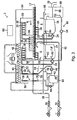
- FIG. 1 , Fig. 2 and Fig. 3 The embodiments of an inventive multitank conveyor-type dishwasher 2 for washing items 10 to be washed which are illustrated in Fig. 1 , Fig. 2 and Fig. 3 have a conveying apparatus 12 for conveying the item 10 to be washed through the multitank conveyor-type dishwasher 2 in a conveying direction 4.
- a belt-conveying apparatus with an endless belt which has fingers for holding items 10 to be washed is illustrated in the drawings.
- the conveying apparatus 12 can furthermore be in the form of a rack-conveying apparatus.
- each wash zone 6, 8 has an associated tank 14, 16 and associated spray nozzles 18, 20 for spraying liquid from the relevant tank onto the item 10 to be washed.
- Each wash zone 6, 8 has an associated circulation pump 22, 24 for delivering liquid from the relevant tank 14, 16 to spray nozzles 18, 20 of the respective wash zone 6, 8.
- the spray nozzles 18, 20 can be arranged in a known manner, for example in a wall of the relevant zone or on a spray pipe, as illustrated in the drawings.
- the front wash zone 8 as seen in the conveying direction 4, is in the form of a recirculating precleaning zone.
- the front wash zone 8 may be in the form of a manual precleaning zone.
- the rear wash zone 6, as seen in the conveying direction 4, is in the form of a main wash zone in which a wash liquid, such as detergent mixed with water, is circulated by means of the pump 22 and is sprayed onto the item 10 to be washed by means of the associated spray nozzles 18.
- a wash liquid such as detergent mixed with water
- the liquid forward-flow apparatus 26 is formed by an overflow channel which connects the tanks 14, 16 of the relevant zones 6, 8 in terms of flow such that liquid from the tank 14 of the rear zone 6 automatically passes into the tank 16 of the front zone 8 when a liquid level in the rear tank exceeds a predetermined level. It is possible to provide a forward-flow line with or without pumping apparatus in place of the overflow channel, as is known, for example, from EP 0 838 190 B1 .
- a recirculating rinsing zone 32 and a fresh-water rinsing zone 34 follow the rear wash zone 6 in the conveying direction 4.
- liquid is supplied predominantly by means of continuous fresh-water rinsing which involves fresh-water rinsing liquid, which contains fresh water or comprises fresh water, being sprayed onto the item 10 to be washed from corresponding spray nozzles 36.
- the water is collected after the first spraying operation (final rinse) and then flows via a cascade system from tank to tank until it reaches the outflow.
- the rinsing liquid is supplied to a heat exchanger 40 via a line 38, the said heat exchanger drawing off heat from the exhaust air and the water vapours of the multitank conveyor-type dishwasher 2 and preheating the rinsing liquid.
- the rinsing liquid is then conducted through a heating apparatus 42 which heats up the rinsing liquid further before it is supplied to the spray nozzles 36 of the fresh-water rinsing zone 34 in order to be sprayed by these spray nozzles 36 onto the item 10 to be washed.
- the heating apparatus 42 can be, for example, a boiler or a throughflow heater.
- the rinsing liquid can be delivered to the spray nozzles 36 using a pump 44 or by means of a sufficient water pressure prevailing in the relevant line.
- a metering device for rinse aid and cleaner is not illustrated in the drawings; a metering device of this type can be provided at the locations which are customary for this.
- the sprayed rinsing liquid flows into a tank 46 which is associated with both the fresh-water rinsing zone 34 and the pump rinsing zone 32.
- a rinsing pump 48 is provided for delivering the rinsing liquid from this tank 46 to the rinsing nozzles 50 by which the rinsing liquid is sprayed onto the item 10 to be washed.
- rinsing liquid delivered by the rinsing pump 48 is supplied to one or more prerinsing nozzles 52.
- the rinsing liquid sprayed by the prerinsing nozzle 52 is used to remove the generally alkali cleaning liquid from the item 10 to be washed.
- the rinsing liquid sprayed by the prerinsing nozzle 52 is supplied to the tank 14 of the rear wash zone 6 through at least one baffle plate 54, the said tank being continuously supplied with liquid in this way.
- a detergent may also be provided to tank 14.
- further spray nozzles can be provided in the respective spray zones 6, 8, 32, 34.
- curtain elements 56 can be provided particularly at the edges of the spray zones of the multitank conveyor-type dishwasher 2, these curtain elements in particular acting as spray protection in order to reduce liquid unintentionally passing between the zones.
- Liquid is deflected from the rear wash zone 6 into the front wash zone 8 and this may be so severe, in particular in the case of a large item 10 to be washed, that the continuous supply of liquid from zone 32 to zone 6 is not sufficient to compensate for the loss of liquid in zone 6.
- a liquid recirculation apparatus 60 is provided for transferring sprayed liquid of the front wash zone 8, as seen in the conveying direction 4, into the rear wash zone 6 which is arranged downstream of the front wash zone 8, as seen in the conveying direction 4, counter to the forward-flow direction 28.
- a lack of liquid in the rear wash zone 6, which occurs on account of liquid being deflected, can be compensated for in particular.
- the liquid recirculation apparatus 60 has a return line 62 and an associated recirculation pump 64 for pumping the liquid of the front wash zone 8 into the rear wash zone 6.
- the liquid recirculation apparatus 60 is designed to supply liquid to the tank 14 which is associated with the rear wash zone 6. Furthermore, the liquid recirculation apparatus 60 can be designed to supply liquid to the spray nozzles 18 of the rear wash zone 6.
- the front wash zone 8 has an overflow 66 which issues into a collecting container 68, and the liquid recirculation apparatus 60 is designed to remove liquid of the front wash zone 8 from the collecting container 68.
- the return line 62 is connected to the collecting container 68.
- the collecting container 68 can have an overflow 70 through which liquid flows out from the collecting container 68 when the liquid level in the collecting container 68 is above the overflow 70.
- the collecting container 68 can have a level sensor 72 and an outlet 74 with a controllable valve 76 which is opened or closed as a function of the liquid level detected by the level sensor 72.
- the liquid recirculation apparatus 60 is designed to remove liquid from the tank 16 which is associated with the front wash zone 8.
- the return line 62 is connected to the tank of the front wash zone 8.
- the multitank conveyor-type dishwasher 2 has a control device 80 for controlling components of the multitank conveyor-type dishwasher 2, in particular for controlling the correspondingly designed liquid recirculation apparatus 60, here the recirculation pump 64.
- the rear wash zone 6 has a level sensor 82 for detecting a liquid level in the tank 14 of the rear wash zone 6, wherein the control device 80 is designed to operate the liquid recirculation apparatus 60 as a function of the liquid level in the tank of the rear wash zone 6.
- the level sensor 82 is in the form of a level switch.
- the control device 80 can be designed to operate the recirculation pump 64 when the liquid level in the tank of the rear wash zone 6 falls below the switching level of the level sensor 82.
- the switching level of the level sensor 82 can, for example, correspond to a setpoint level of the liquid in the tank 14 of the rear wash zone 6.
- the front wash zone 8 has a level sensor 84, which is in the form of a level switch, for detecting a liquid level in the tank 16 which is associated with the front wash zone 8, and the control device 80 is designed to operate the liquid recirculation apparatus 60 as a function of the liquid level in the tank 16 of the front wash zone 8.
- a switching level of the level sensor 84 can, for example, correspond to a setpoint level of the liquid in the tank 16 of the front wash zone 8.
- the control device 80 operates the liquid recirculation apparatus 60 when the liquid level falls below a predetermined level value in the front wash zone 8.
- the liquid recirculation apparatus 60 then delivers liquid from the collecting container 68 to the tank of the rear wash zone 6, liquid flowing from the said tank into the tank of the front wash zone 8 by means of the liquid forward-flow apparatus 26 and raising the liquid level here.
- the control device 80 switches off the liquid recirculation apparatus 60.
- Level sensors which are designed to detect more than two level values may be provided in place of the level switches.
- the amount of liquid supplied to the multitank conveyor-type dishwasher 2 and the corresponding amount of liquid which is flowing out for example the amount of liquid flowing out of the rear wash zone 6, to be measured using corresponding flowmeters (not illustrated), and for the liquid recirculation apparatus 60 to be operated by the control device 80 to recirculate liquid into a rear wash zone 6 when the amount of liquid supplied to the multitank conveyor-type dishwasher is less than the amount of liquid flowing out.
- the multitank conveyor-type dishwasher 2 illustrated in Fig. 1 and Fig. 3 has a turbidity sensor 86 for measuring the degree of contamination of the liquid of the front wash zone 8, and the control device 80 is designed to operate the liquid recirculation apparatus 60 as a function of the degree of contamination of the liquid of the front wash zone 8.
- the turbidity sensor 86 can be arranged in the collecting container 68, as illustrated in Figs 1 and 3 .
- a turbidity sensor can be arranged in the tank 16 of the front wash zone 8 (not illustrated).
- a turbidity sensor can be arranged in the tank of the front wash zone 8 if required.
- the control device 80 may be designed so that it operates the liquid recirculation apparatus 60 only if the degree of contamination of the liquid of the front wash zone 8 is below a predetermined degree of contamination. As a result, undesired contamination of the liquid in the tank 14 of the rear wash zone 6 can be avoided.
- the tank 14 of the rear wash zone 6 may have an associated fresh-water supply apparatus 88, as illustrated in the drawings, using which fresh water can be supplied to the tank 14 of the rear wash zone 6, wherein the control device 80 is designed to operate the fresh-water supply apparatus 88 as a function of a fresh-water requirement and in this way supply fresh water to the tank 14 of the rear wash zone 6.
- the tank 16 of the front wash zone 8 may have an associated fresh-water supply apparatus 88, using which fresh water can be supplied to the front tank (not illustrated).
- Fresh water may be required, for example, when there is too little liquid in the tank of the rear wash zone 6 and the degree of contamination in the tank of the front wash zone 8 is above a predetermined limit value.
- "Too little liquid in the tank 14 of the rear wash zone 6" may, in this case, mean that the level of liquid in the tank 14 of the rear wash zone 6 is below the switching level of the level sensor 82, for example that the level in the tank 14 of the rear wash zone is not sufficient to allow liquid to pass from the tank 14 of the rear zone 6 into the tank 16 of the front zone 8 via the liquid forward-flow apparatus 26.
- a further level sensor 90 may be arranged in the tank 14 of the rear wash zone 6 below the level sensor 82, as illustrated by dashed lines in Fig. 3 by way of example.
- "too little liquid in the tank 14 of the rear wash zone 6" may mean that the liquid level in the tank of the rear wash zone is below the switching level of the further level sensor 90.
- the further level sensor 90 ensures that enough liquid is available for the spray nozzles 18.
- a level which is below a minimum level of the liquid from the front wash zone 8 can be a condition for a fresh-water requirement.
- a level sensor 92 as illustrated by a dashed line in Fig. 3 , which monitors a minimum level in the collecting container 68 may be provided in the collecting container 68.
- fresh water is required when the liquid level in the collecting container 68 is below the minimum level and liquid is required in the rear zone 6.
- a level sensor 94 as illustrated by a dashed line in Fig.
- fresh water may be required, for example, when, in the embodiment of Fig. 2 , the respective liquid level both in the tank 14 of the rear wash zone 6 and in the tank 16 of the front wash zone 8 is below the corresponding setpoint value.
- one preferred embodiment of a multitank conveyor-type dishwasher 2 as illustrated in Fig. 1 and Fig. 3 for example, is designed and can be operated in such a way that a liquid requirement is detected in the rear wash zone, for example by a liquid level in a tank 14 of the rear wash zone 6 being detected, that the degree of contamination of the liquid of the front wash zone 8 is detected, and that, when liquid is required in the rear wash zone 6, liquid of the front wash zone 8 is supplied to the rear wash zone 6 if the degree of contamination is below a predetermined limit value, and that, when liquid is required in the rear wash zone 6, fresh water is supplied to the rear wash zone 6 if the degree of contamination is equal to the predetermined limit value or is above the predetermined limit value.
- provision may be made to supply both fresh water and also liquid of the front wash zone 8, for example simultaneously, successively or alternately at specific time intervals.
- provision may be made for both fresh water and also liquid of the front wash zone 8 to be supplied to the rear wash zone 6 when the degree of contamination of the liquid of the front wash zone 8 is above a predetermined contamination limit value.
- detection includes in particular "automatic detection”.
- one or more further wash zones can be arranged between the front wash zone 8 (preclearing zone) and the rear wash zone 6 (main wash zone).
- the liquid recirculation apparatus 60 may be designed to remove liquid from a further wash zone and/or to transfer the removed liquid into a further wash zone.
Landscapes
- Washing And Drying Of Tableware (AREA)
Claims (10)
- Mehrtank-Transportspülmaschine (2) zum Spülen von Spülgut (10), die eine Transportvorrichtung (12) zum Transport des Spülguts (10) in einer Transportrichtung (4) durch die Mehrtank-Transportspülmaschine (2), mindestens zwei Reinigungszonen (6, 8), die in der Transportrichtung (4) nacheinander angeordnet sind, wobei jeder Reinigungszone (6, 8) ein Tank (14, 16) und Sprühdüsen (18, 20) zum Sprühen von Flüssigkeit aus dem zugeordneten Tank (14, 16) auf das Spülgut (10) zugeordnet sind, und eine Flüssigkeitsvorlaufvorrichtung (26) zwischen jeweils zwei aufeinanderfolgenden Reinigungszonen (6, 8) zur Überführung von Flüssigkeit zwischen diesen Reinigungszonen (6, 8) in einer Vorlaufrichtung (28) entgegen der Transportrichtung (4) umfasst,
dadurch gekennzeichnet, dass
eine Flüssigkeitsrückführvorrichtung (60) zur Überführung von Flüssigkeit vorgesehen ist, die vom Spülgut entgegen der Transportrichtung (4) von einer in der Transportrichtung (4) gesehen vorderen Reinigungszone (8) in eine in der Transportrichtung (4) gesehen stromabwärts von der vorderen Reinigungszone (8) angeordnete hintere Reinigungszone (6) abgelenkt worden ist,
wobei die Flüssigkeitsrückführvorrichtung (60) eine Rückführleitung und eine zugeordnete Pumpe (64) aufweist, um die Flüssigkeit der vorderen Reinigungszone (8) in die hintere Reinigungszone (6) zu pumpen, und
wobei die Flüssigkeitsrückführvorrichtung (60) zum Zuführen von Flüssigkeit in den der hinteren Reinigungszone (6) zugeordneten Tank (14) ausgelegt ist. - Mehrtank-Transportspülmaschine (2) nach Anspruch 1, wobei die Flüssigkeitsrückführvorrichtung (60) dazu ausgelegt ist, Flüssigkeit der vorderen Reinigungszone (8) aus dem der vorderen Reinigungszone (8) zugeordneten Tank (16) zu entnehmen.
- Mehrtank-Transportspülmaschine (2) nach Anspruch 1 oder 2, wobei die vordere Reinigungszone (8) einen Ablauf (66) aufweist, der in einen Sammelbehälter (68) mündet, und wobei die Flüssigkeitsrückführvorrichtung (60) zum Entnehmen von Flüssigkeit der vorderen Reinigungszone (8) aus dem Sammelbehälter (68) ausgelegt ist.
- Mehrtank-Transportspülmaschine (2) nach einem der vorhergehenden Ansprüche, wobei eine Steuereinrichtung (80) zum Steuern von Komponenten der Mehrtank-Transportspülmaschine (2) vorgesehen ist.
- Mehrtank-Transportspülmaschine (2) nach Anspruch 4, wobei die hintere Reinigungszone (6) mindestens einen Niveausensor (82, 90) zum Erfassen eines Flüssigkeitsniveaus in dem der hinteren Reinigungszone (6) zugeordneten Tank (14) aufweist und die Steuereinrichtung (80) zum Betreiben der Flüssigkeitsrückführvorrichtung (60) in Abhängigkeit von dem Flüssigkeitsniveau in dem Tank (14) der hinteren Reinigungszone (6) ausgelegt ist.
- Mehrtank-Transportspülmaschine (2) nach Anspruch 4 oder 5, wobei die vordere Reinigungszone (8) mindestens einen Niveausensor (84, 94) zum Erfassen eines Flüssigkeitsniveaus in dem der vorderen Reinigungszone (8) zugeordneten Tank (16) aufweist und die Steuereinrichtung (80) zum Betreiben der Flüssigkeitsrückführvorrichtung (60) in Abhängigkeit von dem Flüssigkeitsniveau in dem Tank (16) der vorderen Reinigungszone (8) ausgelegt ist.
- Mehrtank-Transportspülmaschine (2) nach einem der Ansprüche 4 bis 6, wobei ein Trübungssensor (86) zum Messen des Verschmutzungsgrades der Flüssigkeit der vorderen Reinigungszone (8) vorgesehen ist und die Steuereinrichtung (80) zum Betreiben der Flüssigkeitsrückführvorrichtung (60) in Abhängigkeit vom Verschmutzungsgrad der Flüssigkeit der vorderen Reinigungszone (8) ausgelegt ist.
- Mehrtank-Transportspülmaschine (2) nach einem der Ansprüche 4 bis 7, wobei dem Tank (14) der hinteren Reinigungszone (6) eine Frischwasserzufuhrvorrichtung (88) zugeordnet ist, mit der dem Tank (14) der hinteren Reinigungszone (6) Frischwasser zuführbar ist, und wobei die Steuereinrichtung (80) zum Betreiben der Frischwasserzufuhrvorrichtung (88) in Abhängigkeit von einem Frischwasserbedarf der hinteren Reinigungszone (6) ausgelegt ist.
- Verfahren zum Betrieb einer Mehrtank-Transportspülmaschine (2), wobei bei einem entsprechenden Flüssigkeitsbedarf in einer in einer Transportrichtung (4) gesehen hinteren Reinigungszone (6) der hinteren Reinigungszone (6) Flüssigkeit einer in der Transportrichtung (4) gesehen vorderen Reinigungszone (8) zugeführt wird,
dadurch gekennzeichnet, dass
bei einem Flüssigkeitsbedarf in der hinteren Reinigungszone (6) Flüssigkeit der vorderen Reinigungszone (8) über eine Rückführleitung und eine zugeordnete Pumpe (64) in einen der hinteren Reinigungszone (6) zugeordneten Tank (14) gepumpt wird. - Verfahren nach Anspruch 9, wobei ein Flüssigkeitsbedarf in der hinteren Reinigungszone (6) erfasst wird, der Verschmutzungsgrad der Flüssigkeit der vorderen Reinigungszone (8) erfasst wird und bei einem Flüssigkeitsbedarf in der hinteren Reinigungszone (6) der hinteren Reinigungszone (6) Flüssigkeit der vorderen Reinigungszone (8) zugeführt wird, wenn der Verschmutzungsgrad unter einem vorbestimmten Grenzwert liegt, und wobei bei Flüssigkeitsbedarf in der hinteren Reinigungszone (6) der hinteren Reinigungszone (6) Frischwasser zugeführt wird, wenn der Verschmutzungsgrad gleich dem vorbestimmten Grenzwert ist oder über dem vorbestimmten Grenzwert liegt.
Applications Claiming Priority (2)
| Application Number | Priority Date | Filing Date | Title |
|---|---|---|---|
| DE102005015157A DE102005015157A1 (de) | 2005-04-02 | 2005-04-02 | Mehrtank-Transportspülmaschine und ein Betriebsverfahren hierfür |
| PCT/US2006/011231 WO2006107650A1 (en) | 2005-04-02 | 2006-03-28 | Multitank conveyor-type dishwasher and an operating method for it |
Publications (2)
| Publication Number | Publication Date |
|---|---|
| EP1868481A1 EP1868481A1 (de) | 2007-12-26 |
| EP1868481B1 true EP1868481B1 (de) | 2010-06-23 |
Family
ID=36646195
Family Applications (1)
| Application Number | Title | Priority Date | Filing Date |
|---|---|---|---|
| EP06739796A Expired - Fee Related EP1868481B1 (de) | 2005-04-02 | 2006-03-28 | Förderbandartiger geschirrspüler mit mehreren behältern und betriebsverfahren dafür |
Country Status (5)
| Country | Link |
|---|---|
| US (1) | US8042557B2 (de) |
| EP (1) | EP1868481B1 (de) |
| CA (1) | CA2601528C (de) |
| DE (2) | DE102005015157A1 (de) |
| WO (1) | WO2006107650A1 (de) |
Cited By (2)
| Publication number | Priority date | Publication date | Assignee | Title |
|---|---|---|---|---|
| WO2015104312A1 (de) | 2014-01-10 | 2015-07-16 | Meiko Maschinenbau Gmbh & Co. Kg | Transportspülmaschine mit mehreren behandlungszonen |
| EP2881028B1 (de) | 2011-07-15 | 2016-06-29 | Comenda Ali S.p.A. | Verbessertes mehrstufiges Spülmodul für Tunnelgeschirrspüler und Tunnelgeschirrspüler mit solch einem Modul |
Families Citing this family (5)
| Publication number | Priority date | Publication date | Assignee | Title |
|---|---|---|---|---|
| DE102007009252A1 (de) | 2007-02-22 | 2008-08-28 | Meiko Maschinenbau Gmbh & Co. Kg | Verfahren zum Betrieb einer Durchlaufgeschirrspülmaschine |
| EP2732748B1 (de) | 2012-11-20 | 2017-01-04 | Premark FEG L.L.C. | System zur erkennung von motorausfällen bei geschirrspülmaschinenpumpen, sowie zugehöriges verfahren |
| DE102014114719A1 (de) * | 2014-10-10 | 2016-04-14 | Winterhalter Gastronom Gmbh | Transportgeschirrspülmaschine |
| CN111772549B (zh) * | 2020-06-15 | 2024-02-09 | 田吉星 | 一种多功能洗碗机 |
| CN114260242B (zh) * | 2021-12-30 | 2022-10-04 | 新昌县海博科技股份有限公司 | 一种网带式清洗机及其清洗方法 |
Family Cites Families (19)
| Publication number | Priority date | Publication date | Assignee | Title |
|---|---|---|---|---|
| DE712150C (de) | 1934-01-21 | 1941-10-13 | Enzinger Union Werke Akt Ges | Reinigungsmaschine fuer Flaschen |
| US2564798A (en) * | 1946-01-25 | 1951-08-21 | James N Allensworth | Washing liquid and drying air-heating means for dishwashers |
| US3789860A (en) * | 1971-11-05 | 1974-02-05 | Hobart Mfg Co | Method and apparatus for treating dishwasher discharge |
| US3849197A (en) * | 1973-03-08 | 1974-11-19 | B Sorrentino | Method and apparatus for decontaminating a rinse liquid |
| US4319930A (en) * | 1980-03-28 | 1982-03-16 | Daiwa Can Company, Limited | Method for multi-stage washing |
| US4326551A (en) * | 1980-10-27 | 1982-04-27 | Hobart Corporation | Heat recovery system for a dishwasher |
| US4357176A (en) * | 1981-02-23 | 1982-11-02 | Anthony John A | System for conserving energy and washing agents in a dishwasher |
| SE8105811L (sv) * | 1981-10-01 | 1983-04-02 | Electrolux Ab | Kontinuerlig diskmaskin |
| US4561904A (en) | 1984-09-21 | 1985-12-31 | Hobart Corporation | Control system and method of controlling a dishwashing machine |
| DE3938755A1 (de) * | 1989-11-23 | 1991-05-29 | Henkel Kgaa | Verfahren zur kontinuierlichen maschinellen reinigung von gebrauchsgeschirr |
| US5038807A (en) * | 1990-04-16 | 1991-08-13 | Ecolab, Inc. | Performance monitoring system for warewashing machines |
| US5287866A (en) * | 1990-10-24 | 1994-02-22 | Hoshizaki Denki Kabushiki Kaisha | Dishwashing system |
| DE4311064A1 (de) | 1993-04-03 | 1994-10-06 | Lang Apparatebau Gmbh | Verfahren zur Messung der Schmutzbefrachtung einer Waschflotte |
| DE19644438C2 (de) * | 1996-10-25 | 1998-11-12 | Premark Feg L L C N D Ges D St | Durchlaufgeschirrspülvorrichtung sowie Verfahren zum Reinigen von Geschirr- und/oder Tabletteilen |
| DE19836739A1 (de) | 1998-08-13 | 2000-02-17 | Meiko Maschinenbau Gmbh & Co | Geschirrspülmaschine |
| EP1046370A1 (de) * | 1999-04-19 | 2000-10-25 | CHEMISCHE FABRIK DR. WEIGERT (GMBH & CO.) | Bandspülmaschine |
| MXPA02000949A (es) * | 1999-07-27 | 2002-07-30 | Unilever Nv | Metodo y dispositivo de monitoreo para monitorear un proceso de lavado. |
| US6530996B2 (en) * | 2000-07-13 | 2003-03-11 | Fuuga-Controls Oy | Method for washing items |
| DE10253017B4 (de) | 2002-11-14 | 2004-09-09 | Whirlpool Corp., Benton Harbor | Verfahren zum Betreiben einer Geschirrspülmaschine mit einer zentralen Steuereinheit |
-
2005
- 2005-04-02 DE DE102005015157A patent/DE102005015157A1/de not_active Withdrawn
-
2006
- 2006-03-28 CA CA2601528A patent/CA2601528C/en not_active Expired - Fee Related
- 2006-03-28 DE DE602006015041T patent/DE602006015041D1/de active Active
- 2006-03-28 EP EP06739796A patent/EP1868481B1/de not_active Expired - Fee Related
- 2006-03-28 WO PCT/US2006/011231 patent/WO2006107650A1/en active Application Filing
- 2006-03-28 US US11/909,722 patent/US8042557B2/en not_active Expired - Fee Related
Cited By (3)
| Publication number | Priority date | Publication date | Assignee | Title |
|---|---|---|---|---|
| EP2881028B1 (de) | 2011-07-15 | 2016-06-29 | Comenda Ali S.p.A. | Verbessertes mehrstufiges Spülmodul für Tunnelgeschirrspüler und Tunnelgeschirrspüler mit solch einem Modul |
| WO2015104312A1 (de) | 2014-01-10 | 2015-07-16 | Meiko Maschinenbau Gmbh & Co. Kg | Transportspülmaschine mit mehreren behandlungszonen |
| DE102014000448A1 (de) | 2014-01-10 | 2015-07-16 | Meiko Maschinenbau Gmbh & Co. Kg | Transportspülmaschine mit mehreren Behandlungszonen |
Also Published As
| Publication number | Publication date |
|---|---|
| US8042557B2 (en) | 2011-10-25 |
| WO2006107650A1 (en) | 2006-10-12 |
| US20090277477A1 (en) | 2009-11-12 |
| EP1868481A1 (de) | 2007-12-26 |
| DE102005015157A1 (de) | 2006-10-05 |
| CA2601528A1 (en) | 2006-10-12 |
| DE602006015041D1 (de) | 2010-08-05 |
| CA2601528C (en) | 2011-02-01 |
Similar Documents
| Publication | Publication Date | Title |
|---|---|---|
| EP1868481B1 (de) | Förderbandartiger geschirrspüler mit mehreren behältern und betriebsverfahren dafür | |
| CN1972623B (zh) | 传送带式餐具清洗机及其运行方法 | |
| US7938913B2 (en) | Conveyor dishwasher and operating method for same | |
| CN101977699B (zh) | 传送式器皿清洗机及其使用方法 | |
| EP2346619B1 (de) | System zum waschen von spülgut und verfahren zum betreiben eines derartigen systems | |
| CN1972624B (zh) | 传送带式餐具清洗机及其运行方法 | |
| CN100563545C (zh) | 传送带式餐具清洗机及其运行方法 | |
| US10335011B2 (en) | Cleaning device having an individually switchable rinsing nozzle system | |
| US20060213543A1 (en) | Conveyor-type dishwasher and method for it | |
| CN106659355B (zh) | 器皿清洗机的清洗臂过滤器装置 | |
| US20090159097A1 (en) | Dishwasher in the form of a programmable machine and its operating method | |
| CN1972620B (zh) | 传送带式餐具清洗机及其运行方法 | |
| EP2818089B1 (de) | Geschirrspülmaschine der Fördererart | |
| EP3280309B1 (de) | Förderbandartiger geschirrspüler und verfahren für den betrieb eines förderbandartigen geschirrspülers | |
| CN108289587B (zh) | 器皿清洗机怠速系统和方法 | |
| JP2012152676A (ja) | 洗浄装置 | |
| EP3280308B1 (de) | Förderbandartiger geschirrspüler und verfahren für den betrieb eines förderbandartigen geschirrspülers | |
| EP3424400B1 (de) | Verfahren zum betrieb einer professionellen tunnelgeschirrspülmaschine | |
| US20240099541A1 (en) | Conveyor warewasher and method for operating a conveyor warewasher | |
| WO2009023466A1 (en) | Dishwasher and method for cleaning items to be washed with such a diswasher |
Legal Events
| Date | Code | Title | Description |
|---|---|---|---|
| PUAI | Public reference made under article 153(3) epc to a published international application that has entered the european phase |
Free format text: ORIGINAL CODE: 0009012 |
|
| 17P | Request for examination filed |
Effective date: 20070831 |
|
| AK | Designated contracting states |
Kind code of ref document: A1 Designated state(s): DE FR GB IT |
|
| RIN1 | Information on inventor provided before grant (corrected) |
Inventor name: BERNER, DIETRICH Inventor name: PADTBERG, KLAUS Inventor name: DISCH, HARALD |
|
| DAX | Request for extension of the european patent (deleted) | ||
| RBV | Designated contracting states (corrected) |
Designated state(s): DE FR GB IT |
|
| 17Q | First examination report despatched |
Effective date: 20090107 |
|
| R17C | First examination report despatched (corrected) |
Effective date: 20090126 |
|
| GRAP | Despatch of communication of intention to grant a patent |
Free format text: ORIGINAL CODE: EPIDOSNIGR1 |
|
| GRAS | Grant fee paid |
Free format text: ORIGINAL CODE: EPIDOSNIGR3 |
|
| GRAA | (expected) grant |
Free format text: ORIGINAL CODE: 0009210 |
|
| AK | Designated contracting states |
Kind code of ref document: B1 Designated state(s): DE FR GB IT |
|
| REF | Corresponds to: |
Ref document number: 602006015041 Country of ref document: DE Date of ref document: 20100805 Kind code of ref document: P |
|
| PLBE | No opposition filed within time limit |
Free format text: ORIGINAL CODE: 0009261 |
|
| STAA | Information on the status of an ep patent application or granted ep patent |
Free format text: STATUS: NO OPPOSITION FILED WITHIN TIME LIMIT |
|
| 26N | No opposition filed |
Effective date: 20110324 |
|
| REG | Reference to a national code |
Ref country code: DE Ref legal event code: R097 Ref document number: 602006015041 Country of ref document: DE Effective date: 20110323 |
|
| PGFP | Annual fee paid to national office [announced via postgrant information from national office to epo] |
Ref country code: FR Payment date: 20120406 Year of fee payment: 7 |
|
| PGFP | Annual fee paid to national office [announced via postgrant information from national office to epo] |
Ref country code: GB Payment date: 20120326 Year of fee payment: 7 Ref country code: IT Payment date: 20120323 Year of fee payment: 7 |
|
| PGFP | Annual fee paid to national office [announced via postgrant information from national office to epo] |
Ref country code: DE Payment date: 20130327 Year of fee payment: 8 |
|
| GBPC | Gb: european patent ceased through non-payment of renewal fee |
Effective date: 20130328 |
|
| REG | Reference to a national code |
Ref country code: FR Ref legal event code: ST Effective date: 20131129 |
|
| PG25 | Lapsed in a contracting state [announced via postgrant information from national office to epo] |
Ref country code: GB Free format text: LAPSE BECAUSE OF NON-PAYMENT OF DUE FEES Effective date: 20130328 Ref country code: FR Free format text: LAPSE BECAUSE OF NON-PAYMENT OF DUE FEES Effective date: 20130402 |
|
| PG25 | Lapsed in a contracting state [announced via postgrant information from national office to epo] |
Ref country code: IT Free format text: LAPSE BECAUSE OF NON-PAYMENT OF DUE FEES Effective date: 20130328 |
|
| REG | Reference to a national code |
Ref country code: DE Ref legal event code: R119 Ref document number: 602006015041 Country of ref document: DE |
|
| REG | Reference to a national code |
Ref country code: DE Ref legal event code: R119 Ref document number: 602006015041 Country of ref document: DE Effective date: 20141001 |
|
| PG25 | Lapsed in a contracting state [announced via postgrant information from national office to epo] |
Ref country code: DE Free format text: LAPSE BECAUSE OF NON-PAYMENT OF DUE FEES Effective date: 20141001 |