EP1867390A1 - Procede de traitement de sulfure d hydrogene, procede de production d hydrogene et reacteur de photocatalyseur - Google Patents
Procede de traitement de sulfure d hydrogene, procede de production d hydrogene et reacteur de photocatalyseur Download PDFInfo
- Publication number
- EP1867390A1 EP1867390A1 EP06730518A EP06730518A EP1867390A1 EP 1867390 A1 EP1867390 A1 EP 1867390A1 EP 06730518 A EP06730518 A EP 06730518A EP 06730518 A EP06730518 A EP 06730518A EP 1867390 A1 EP1867390 A1 EP 1867390A1
- Authority
- EP
- European Patent Office
- Prior art keywords
- photocatalyst
- hydrogen sulfide
- liquid
- electrode
- liquid tank
- Prior art date
- Legal status (The legal status is an assumption and is not a legal conclusion. Google has not performed a legal analysis and makes no representation as to the accuracy of the status listed.)
- Withdrawn
Links
- 229910000037 hydrogen sulfide Inorganic materials 0.000 title claims abstract description 136
- RWSOTUBLDIXVET-UHFFFAOYSA-N Dihydrogen sulfide Chemical compound S RWSOTUBLDIXVET-UHFFFAOYSA-N 0.000 title claims abstract description 133
- 239000011941 photocatalyst Substances 0.000 title claims abstract description 126
- 229910052739 hydrogen Inorganic materials 0.000 title claims abstract description 71
- 239000001257 hydrogen Substances 0.000 title claims abstract description 71
- UFHFLCQGNIYNRP-UHFFFAOYSA-N Hydrogen Chemical compound [H][H] UFHFLCQGNIYNRP-UHFFFAOYSA-N 0.000 title claims abstract description 61
- 238000000034 method Methods 0.000 title claims abstract description 59
- 238000004519 manufacturing process Methods 0.000 title description 9
- 239000007788 liquid Substances 0.000 claims abstract description 128
- 229910052751 metal Inorganic materials 0.000 claims abstract description 58
- 239000002184 metal Substances 0.000 claims abstract description 58
- 238000005341 cation exchange Methods 0.000 claims abstract description 21
- 239000012528 membrane Substances 0.000 claims abstract description 21
- 239000000126 substance Substances 0.000 claims abstract description 16
- 239000003929 acidic solution Substances 0.000 claims abstract description 13
- 229910052976 metal sulfide Inorganic materials 0.000 claims abstract description 9
- 239000010419 fine particle Substances 0.000 claims abstract description 7
- 239000002088 nanocapsule Substances 0.000 claims abstract description 7
- 239000007789 gas Substances 0.000 claims description 62
- CURLTUGMZLYLDI-UHFFFAOYSA-N Carbon dioxide Chemical compound O=C=O CURLTUGMZLYLDI-UHFFFAOYSA-N 0.000 claims description 50
- 239000000243 solution Substances 0.000 claims description 48
- 239000001569 carbon dioxide Substances 0.000 claims description 25
- 229910002092 carbon dioxide Inorganic materials 0.000 claims description 25
- CRVGTESFCCXCTH-UHFFFAOYSA-N methyl diethanolamine Chemical compound OCCN(C)CCO CRVGTESFCCXCTH-UHFFFAOYSA-N 0.000 claims description 22
- 238000013032 photocatalytic reaction Methods 0.000 claims description 22
- 239000000463 material Substances 0.000 claims description 17
- 230000005587 bubbling Effects 0.000 claims description 16
- 238000005192 partition Methods 0.000 claims description 10
- 238000010438 heat treatment Methods 0.000 claims description 5
- 150000002431 hydrogen Chemical class 0.000 claims description 5
- 238000000354 decomposition reaction Methods 0.000 abstract description 6
- BASFCYQUMIYNBI-UHFFFAOYSA-N platinum Chemical compound [Pt] BASFCYQUMIYNBI-UHFFFAOYSA-N 0.000 description 17
- -1 hydrogen ions Chemical class 0.000 description 15
- 238000005406 washing Methods 0.000 description 15
- 238000005868 electrolysis reaction Methods 0.000 description 14
- 229910052724 xenon Inorganic materials 0.000 description 13
- FHNFHKCVQCLJFQ-UHFFFAOYSA-N xenon atom Chemical compound [Xe] FHNFHKCVQCLJFQ-UHFFFAOYSA-N 0.000 description 13
- HEMHJVSKTPXQMS-UHFFFAOYSA-M Sodium hydroxide Chemical compound [OH-].[Na+] HEMHJVSKTPXQMS-UHFFFAOYSA-M 0.000 description 12
- QAOWNCQODCNURD-UHFFFAOYSA-N Sulfuric acid Chemical compound OS(O)(=O)=O QAOWNCQODCNURD-UHFFFAOYSA-N 0.000 description 12
- XLYOFNOQVPJJNP-UHFFFAOYSA-N water Substances O XLYOFNOQVPJJNP-UHFFFAOYSA-N 0.000 description 11
- NINIDFKCEFEMDL-UHFFFAOYSA-N Sulfur Chemical compound [S] NINIDFKCEFEMDL-UHFFFAOYSA-N 0.000 description 10
- 238000006243 chemical reaction Methods 0.000 description 9
- 229910052717 sulfur Inorganic materials 0.000 description 9
- 239000011593 sulfur Substances 0.000 description 9
- RAHZWNYVWXNFOC-UHFFFAOYSA-N Sulphur dioxide Chemical compound O=S=O RAHZWNYVWXNFOC-UHFFFAOYSA-N 0.000 description 8
- RTAQQCXQSZGOHL-UHFFFAOYSA-N Titanium Chemical compound [Ti] RTAQQCXQSZGOHL-UHFFFAOYSA-N 0.000 description 8
- 229910052697 platinum Inorganic materials 0.000 description 8
- 229910052719 titanium Inorganic materials 0.000 description 8
- 239000010936 titanium Substances 0.000 description 8
- 239000004925 Acrylic resin Substances 0.000 description 7
- 229920000178 Acrylic resin Polymers 0.000 description 7
- 238000002474 experimental method Methods 0.000 description 7
- PXHVJJICTQNCMI-UHFFFAOYSA-N Nickel Chemical compound [Ni] PXHVJJICTQNCMI-UHFFFAOYSA-N 0.000 description 6
- 239000003054 catalyst Substances 0.000 description 6
- 239000003574 free electron Substances 0.000 description 6
- WABPQHHGFIMREM-UHFFFAOYSA-N lead(0) Chemical compound [Pb] WABPQHHGFIMREM-UHFFFAOYSA-N 0.000 description 6
- 239000011347 resin Substances 0.000 description 6
- 229920005989 resin Polymers 0.000 description 6
- BZHJMEDXRYGGRV-UHFFFAOYSA-N Vinyl chloride Chemical compound ClC=C BZHJMEDXRYGGRV-UHFFFAOYSA-N 0.000 description 5
- 229910052980 cadmium sulfide Inorganic materials 0.000 description 5
- 230000003197 catalytic effect Effects 0.000 description 5
- 238000006477 desulfuration reaction Methods 0.000 description 5
- 230000023556 desulfurization Effects 0.000 description 5
- WUPHOULIZUERAE-UHFFFAOYSA-N 3-(oxolan-2-yl)propanoic acid Chemical compound OC(=O)CCC1CCCO1 WUPHOULIZUERAE-UHFFFAOYSA-N 0.000 description 4
- 239000010779 crude oil Substances 0.000 description 4
- 238000004090 dissolution Methods 0.000 description 4
- 230000000694 effects Effects 0.000 description 4
- 230000000977 initiatory effect Effects 0.000 description 4
- 150000002500 ions Chemical class 0.000 description 4
- 238000005259 measurement Methods 0.000 description 4
- 238000006722 reduction reaction Methods 0.000 description 4
- 239000010865 sewage Substances 0.000 description 4
- OKKJLVBELUTLKV-UHFFFAOYSA-N Methanol Chemical compound OC OKKJLVBELUTLKV-UHFFFAOYSA-N 0.000 description 3
- 230000002378 acidificating effect Effects 0.000 description 3
- 239000003513 alkali Substances 0.000 description 3
- 239000002585 base Substances 0.000 description 3
- 239000000470 constituent Substances 0.000 description 3
- 230000007613 environmental effect Effects 0.000 description 3
- 239000003344 environmental pollutant Substances 0.000 description 3
- 239000011521 glass Substances 0.000 description 3
- 229910052759 nickel Inorganic materials 0.000 description 3
- 230000003647 oxidation Effects 0.000 description 3
- 238000007254 oxidation reaction Methods 0.000 description 3
- 229920001021 polysulfide Polymers 0.000 description 3
- 239000005077 polysulfide Substances 0.000 description 3
- 150000008117 polysulfides Polymers 0.000 description 3
- 238000000926 separation method Methods 0.000 description 3
- 239000010409 thin film Substances 0.000 description 3
- 239000002351 wastewater Substances 0.000 description 3
- QGZKDVFQNNGYKY-UHFFFAOYSA-N Ammonia Chemical compound N QGZKDVFQNNGYKY-UHFFFAOYSA-N 0.000 description 2
- RYGMFSIKBFXOCR-UHFFFAOYSA-N Copper Chemical compound [Cu] RYGMFSIKBFXOCR-UHFFFAOYSA-N 0.000 description 2
- HCHKCACWOHOZIP-UHFFFAOYSA-N Zinc Chemical compound [Zn] HCHKCACWOHOZIP-UHFFFAOYSA-N 0.000 description 2
- 238000005273 aeration Methods 0.000 description 2
- GPRLSGONYQIRFK-UHFFFAOYSA-N hydron Chemical compound [H+] GPRLSGONYQIRFK-UHFFFAOYSA-N 0.000 description 2
- 239000002917 insecticide Substances 0.000 description 2
- 238000011835 investigation Methods 0.000 description 2
- VNWKTOKETHGBQD-UHFFFAOYSA-N methane Chemical compound C VNWKTOKETHGBQD-UHFFFAOYSA-N 0.000 description 2
- 239000002245 particle Substances 0.000 description 2
- 239000003208 petroleum Substances 0.000 description 2
- 229910052725 zinc Inorganic materials 0.000 description 2
- 239000011701 zinc Substances 0.000 description 2
- OKTJSMMVPCPJKN-UHFFFAOYSA-N Carbon Chemical compound [C] OKTJSMMVPCPJKN-UHFFFAOYSA-N 0.000 description 1
- 241000270722 Crocodylidae Species 0.000 description 1
- UEEJHVSXFDXPFK-UHFFFAOYSA-N N-dimethylaminoethanol Chemical compound CN(C)CCO UEEJHVSXFDXPFK-UHFFFAOYSA-N 0.000 description 1
- UCKMPCXJQFINFW-UHFFFAOYSA-N Sulphide Chemical compound [S-2] UCKMPCXJQFINFW-UHFFFAOYSA-N 0.000 description 1
- 241000276425 Xiphophorus maculatus Species 0.000 description 1
- 239000005083 Zinc sulfide Substances 0.000 description 1
- QCWXUUIWCKQGHC-UHFFFAOYSA-N Zirconium Chemical compound [Zr] QCWXUUIWCKQGHC-UHFFFAOYSA-N 0.000 description 1
- 238000010521 absorption reaction Methods 0.000 description 1
- 230000001464 adherent effect Effects 0.000 description 1
- 238000003915 air pollution Methods 0.000 description 1
- 229910021529 ammonia Inorganic materials 0.000 description 1
- 150000001450 anions Chemical class 0.000 description 1
- 230000000844 anti-bacterial effect Effects 0.000 description 1
- 238000010420 art technique Methods 0.000 description 1
- 244000052616 bacterial pathogen Species 0.000 description 1
- 229910052799 carbon Inorganic materials 0.000 description 1
- 238000006555 catalytic reaction Methods 0.000 description 1
- 239000003795 chemical substances by application Substances 0.000 description 1
- 238000004140 cleaning Methods 0.000 description 1
- 239000011248 coating agent Substances 0.000 description 1
- 238000000576 coating method Methods 0.000 description 1
- 150000001875 compounds Chemical class 0.000 description 1
- 238000009833 condensation Methods 0.000 description 1
- 230000005494 condensation Effects 0.000 description 1
- 229960002887 deanol Drugs 0.000 description 1
- 230000007423 decrease Effects 0.000 description 1
- LNNWVNGFPYWNQE-GMIGKAJZSA-N desomorphine Chemical compound C1C2=CC=C(O)C3=C2[C@]24CCN(C)[C@H]1[C@@H]2CCC[C@@H]4O3 LNNWVNGFPYWNQE-GMIGKAJZSA-N 0.000 description 1
- 230000003009 desulfurizing effect Effects 0.000 description 1
- 239000012972 dimethylethanolamine Substances 0.000 description 1
- 238000009713 electroplating Methods 0.000 description 1
- 230000002349 favourable effect Effects 0.000 description 1
- 239000000383 hazardous chemical Substances 0.000 description 1
- 238000005984 hydrogenation reaction Methods 0.000 description 1
- RWSOTUBLDIXVET-UHFFFAOYSA-M hydrosulfide Chemical compound [SH-] RWSOTUBLDIXVET-UHFFFAOYSA-M 0.000 description 1
- 238000007654 immersion Methods 0.000 description 1
- 239000004615 ingredient Substances 0.000 description 1
- 230000001678 irradiating effect Effects 0.000 description 1
- 239000003595 mist Substances 0.000 description 1
- 239000000203 mixture Substances 0.000 description 1
- 239000003345 natural gas Substances 0.000 description 1
- 231100000956 nontoxicity Toxicity 0.000 description 1
- 230000001590 oxidative effect Effects 0.000 description 1
- 230000035699 permeability Effects 0.000 description 1
- 231100000719 pollutant Toxicity 0.000 description 1
- 239000002244 precipitate Substances 0.000 description 1
- 238000004321 preservation Methods 0.000 description 1
- 239000002994 raw material Substances 0.000 description 1
- 230000035484 reaction time Effects 0.000 description 1
- 238000005215 recombination Methods 0.000 description 1
- 230000006798 recombination Effects 0.000 description 1
- 238000011084 recovery Methods 0.000 description 1
- 238000007670 refining Methods 0.000 description 1
- 239000004065 semiconductor Substances 0.000 description 1
- 239000010703 silicon Substances 0.000 description 1
- 229910052710 silicon Inorganic materials 0.000 description 1
- 229910052979 sodium sulfide Inorganic materials 0.000 description 1
- GRVFOGOEDUUMBP-UHFFFAOYSA-N sodium sulfide (anhydrous) Chemical compound [Na+].[Na+].[S-2] GRVFOGOEDUUMBP-UHFFFAOYSA-N 0.000 description 1
- 238000001179 sorption measurement Methods 0.000 description 1
- 150000003464 sulfur compounds Chemical class 0.000 description 1
- 231100000331 toxic Toxicity 0.000 description 1
- 230000002588 toxic effect Effects 0.000 description 1
- 230000000007 visual effect Effects 0.000 description 1
- 238000010792 warming Methods 0.000 description 1
- 229910052984 zinc sulfide Inorganic materials 0.000 description 1
- DRDVZXDWVBGGMH-UHFFFAOYSA-N zinc;sulfide Chemical compound [S-2].[Zn+2] DRDVZXDWVBGGMH-UHFFFAOYSA-N 0.000 description 1
- 229910052726 zirconium Inorganic materials 0.000 description 1
Images


Classifications
-
- B—PERFORMING OPERATIONS; TRANSPORTING
- B01—PHYSICAL OR CHEMICAL PROCESSES OR APPARATUS IN GENERAL
- B01D—SEPARATION
- B01D53/00—Separation of gases or vapours; Recovering vapours of volatile solvents from gases; Chemical or biological purification of waste gases, e.g. engine exhaust gases, smoke, fumes, flue gases, aerosols
- B01D53/34—Chemical or biological purification of waste gases
- B01D53/46—Removing components of defined structure
- B01D53/48—Sulfur compounds
- B01D53/52—Hydrogen sulfide
-
- B—PERFORMING OPERATIONS; TRANSPORTING
- B01—PHYSICAL OR CHEMICAL PROCESSES OR APPARATUS IN GENERAL
- B01D—SEPARATION
- B01D53/00—Separation of gases or vapours; Recovering vapours of volatile solvents from gases; Chemical or biological purification of waste gases, e.g. engine exhaust gases, smoke, fumes, flue gases, aerosols
- B01D53/34—Chemical or biological purification of waste gases
- B01D53/74—General processes for purification of waste gases; Apparatus or devices specially adapted therefor
- B01D53/86—Catalytic processes
- B01D53/8603—Removing sulfur compounds
- B01D53/8612—Hydrogen sulfide
-
- B—PERFORMING OPERATIONS; TRANSPORTING
- B01—PHYSICAL OR CHEMICAL PROCESSES OR APPARATUS IN GENERAL
- B01J—CHEMICAL OR PHYSICAL PROCESSES, e.g. CATALYSIS OR COLLOID CHEMISTRY; THEIR RELEVANT APPARATUS
- B01J21/00—Catalysts comprising the elements, oxides, or hydroxides of magnesium, boron, aluminium, carbon, silicon, titanium, zirconium, or hafnium
- B01J21/06—Silicon, titanium, zirconium or hafnium; Oxides or hydroxides thereof
-
- C—CHEMISTRY; METALLURGY
- C01—INORGANIC CHEMISTRY
- C01B—NON-METALLIC ELEMENTS; COMPOUNDS THEREOF; METALLOIDS OR COMPOUNDS THEREOF NOT COVERED BY SUBCLASS C01C
- C01B17/00—Sulfur; Compounds thereof
- C01B17/16—Hydrogen sulfides
-
- C—CHEMISTRY; METALLURGY
- C01—INORGANIC CHEMISTRY
- C01B—NON-METALLIC ELEMENTS; COMPOUNDS THEREOF; METALLOIDS OR COMPOUNDS THEREOF NOT COVERED BY SUBCLASS C01C
- C01B3/00—Hydrogen; Gaseous mixtures containing hydrogen; Separation of hydrogen from mixtures containing it; Purification of hydrogen
- C01B3/02—Production of hydrogen or of gaseous mixtures containing a substantial proportion of hydrogen
- C01B3/04—Production of hydrogen or of gaseous mixtures containing a substantial proportion of hydrogen by decomposition of inorganic compounds, e.g. ammonia
-
- C—CHEMISTRY; METALLURGY
- C25—ELECTROLYTIC OR ELECTROPHORETIC PROCESSES; APPARATUS THEREFOR
- C25B—ELECTROLYTIC OR ELECTROPHORETIC PROCESSES FOR THE PRODUCTION OF COMPOUNDS OR NON-METALS; APPARATUS THEREFOR
- C25B1/00—Electrolytic production of inorganic compounds or non-metals
- C25B1/50—Processes
- C25B1/55—Photoelectrolysis
-
- B—PERFORMING OPERATIONS; TRANSPORTING
- B01—PHYSICAL OR CHEMICAL PROCESSES OR APPARATUS IN GENERAL
- B01J—CHEMICAL OR PHYSICAL PROCESSES, e.g. CATALYSIS OR COLLOID CHEMISTRY; THEIR RELEVANT APPARATUS
- B01J27/00—Catalysts comprising the elements or compounds of halogens, sulfur, selenium, tellurium, phosphorus or nitrogen; Catalysts comprising carbon compounds
- B01J27/02—Sulfur, selenium or tellurium; Compounds thereof
- B01J27/04—Sulfides
-
- B—PERFORMING OPERATIONS; TRANSPORTING
- B01—PHYSICAL OR CHEMICAL PROCESSES OR APPARATUS IN GENERAL
- B01J—CHEMICAL OR PHYSICAL PROCESSES, e.g. CATALYSIS OR COLLOID CHEMISTRY; THEIR RELEVANT APPARATUS
- B01J35/00—Catalysts, in general, characterised by their form or physical properties
- B01J35/30—Catalysts, in general, characterised by their form or physical properties characterised by their physical properties
- B01J35/39—Photocatalytic properties
-
- Y—GENERAL TAGGING OF NEW TECHNOLOGICAL DEVELOPMENTS; GENERAL TAGGING OF CROSS-SECTIONAL TECHNOLOGIES SPANNING OVER SEVERAL SECTIONS OF THE IPC; TECHNICAL SUBJECTS COVERED BY FORMER USPC CROSS-REFERENCE ART COLLECTIONS [XRACs] AND DIGESTS
- Y02—TECHNOLOGIES OR APPLICATIONS FOR MITIGATION OR ADAPTATION AGAINST CLIMATE CHANGE
- Y02E—REDUCTION OF GREENHOUSE GAS [GHG] EMISSIONS, RELATED TO ENERGY GENERATION, TRANSMISSION OR DISTRIBUTION
- Y02E60/00—Enabling technologies; Technologies with a potential or indirect contribution to GHG emissions mitigation
- Y02E60/30—Hydrogen technology
- Y02E60/32—Hydrogen storage
-
- Y—GENERAL TAGGING OF NEW TECHNOLOGICAL DEVELOPMENTS; GENERAL TAGGING OF CROSS-SECTIONAL TECHNOLOGIES SPANNING OVER SEVERAL SECTIONS OF THE IPC; TECHNICAL SUBJECTS COVERED BY FORMER USPC CROSS-REFERENCE ART COLLECTIONS [XRACs] AND DIGESTS
- Y02—TECHNOLOGIES OR APPLICATIONS FOR MITIGATION OR ADAPTATION AGAINST CLIMATE CHANGE
- Y02E—REDUCTION OF GREENHOUSE GAS [GHG] EMISSIONS, RELATED TO ENERGY GENERATION, TRANSMISSION OR DISTRIBUTION
- Y02E60/00—Enabling technologies; Technologies with a potential or indirect contribution to GHG emissions mitigation
- Y02E60/30—Hydrogen technology
- Y02E60/36—Hydrogen production from non-carbon containing sources, e.g. by water electrolysis
-
- Y—GENERAL TAGGING OF NEW TECHNOLOGICAL DEVELOPMENTS; GENERAL TAGGING OF CROSS-SECTIONAL TECHNOLOGIES SPANNING OVER SEVERAL SECTIONS OF THE IPC; TECHNICAL SUBJECTS COVERED BY FORMER USPC CROSS-REFERENCE ART COLLECTIONS [XRACs] AND DIGESTS
- Y02—TECHNOLOGIES OR APPLICATIONS FOR MITIGATION OR ADAPTATION AGAINST CLIMATE CHANGE
- Y02P—CLIMATE CHANGE MITIGATION TECHNOLOGIES IN THE PRODUCTION OR PROCESSING OF GOODS
- Y02P20/00—Technologies relating to chemical industry
- Y02P20/10—Process efficiency
- Y02P20/133—Renewable energy sources, e.g. sunlight
Definitions
- the present invention relates to methods of using a photocatalyst which are utilizable in fields such as the field of chemical industry where hydrogen, sulfur, or the like is necessary, the field of chemical industry where hydrogen sulfide or the like generated in a desulfurization or another step is treated, and the field of environmental preservation where malodorous substances and atmospheric pollutants are removed.
- photocatalyst techniques have come to be practically used while taking advantage of the property of accelerating various chemical reactions including the decomposition of environmental pollutants, malodorous components/various germs, etc. Examples thereof include antibacterial tiles for use in operating rooms in hospitals, filters for air cleaners and air conditioners, and glasses for, e.g., the lighting of expressways or the like.
- investigations are being made for the purpose of causing a photocatalyst to act on water or the like to obtain hydrogen or to act on carbon dioxide to fix/reduce the carbon.
- the step of crude-oil desulfurization presently in general use is as follows.
- the heavy naphtha is subjected to hydrofining, whereby all the sulfur ingredients contained in the crude oil are converted to hydrogen sulfide and recovered.
- This hydrogen sulfide is treated by the process called the Claus process and recovered through sulfur oxidation.
- the Claus process is a process in which one-third of the hydrogen sulfide is oxidized to sulfur dioxide and this sulfur dioxide is reacted with the remaining hydrogen sulfide to obtain elemental sulfur.
- photocatalysts heretofore in use have had the following problems to be overcome.
- their catalytic activity is low.
- the photocatalysts are toxic.
- photocatalysts generate free electrons and free holes upon irradiation with a light, it is highly probable that these free electrons and free holes recombine.
- Low catalytic activity hence results.
- the catalysts have a short life.
- the catalysts generate free electrons and free holes upon irradiation with a light
- the catalysts themselves are oxidized/reduced, besides a target chemical substance, due to the strong oxidation/reduction reactions caused by the free electrons and holes. Namely, there is a problem of photodissolution that the catalysts thus dissolve away and lose their catalytic activity.
- patent document 1 discloses a photocatalyst having high catalytic activity, no toxicity, and a long life. There is a statement therein to the effect that those three problems have been eliminated. Also known is a method of treating hydrogen sulfide or method of producing hydrogen in which a stratified-structure electrode comprising a photocatalyst activated with a metal is used. Patent Document 1: JP-A-2001-190964
- the stratified-structure electrode has the following problem.
- the metal side is corroded by hydrogen sulfide or polysulfide ions (S 2 2- ) are adsorbed onto the metal surface to form a sulfide.
- the electrode thus comes to have no metal surface part for forming hydrogen gas from hydrogen ions (H + ) and becomes incapable of generating hydrogen gas.
- That method employing the stratified-structure electrode has been still unsatisfactory with respect to efficiency. Accordingly, an object of the invention is to eliminate the drawbacks of prior-art techniques described above and provide: a technique enabling highly efficient hydrogen sulfide decomposition and hydrogen generation with a photocatalyst; and apparatus for use in this technique.
- the present invention is as follows.
- the direct decomposition of hydrogen sulfide on a photocatalyst electrode and the production of hydrogen on a metal electrode can be efficiently conducted with light energy such as, e.g., visible light.
- Fig. 1 is a view diagrammatically illustrating one embodiment the apparatus of the invention for treating hydrogen sulfide and producing hydrogen.
- the apparatus shown in Fig. 1 is operated on a basic principle in which the electrolysis of a raw liquid is conducted by means of the photoelectromotive force generated between a semiconductor photocatalyst electrode and a metal electrode. The constitution of the apparatus is explained first and effects thereof are explained next.
- a cell 11 for electrolysis has been partitioned with a cation-exchange membrane 3.
- a photocatalyst electrode 1 and a metal electrode 2 have been disposed on the anode side (left side in Fig. 1) and the cathode side (right side in Fig. 1), respectively.
- This apparatus has been constituted so that the photocatalyst electrode 1 and the metal electrode 2 are electrically connected to each other with a lead wire 4 which is a conductive member.
- a liquid containing hydrogen sulfide and other substances is electrolyzed with the photoelectromotive force generated between the photocatalyst electrode 1 and the metal electrode 2.
- Hydrogen sulfide ions (HS - ) present in the aqueous hydrogen sulfide solution are decomposed with light energy into hydrogen ions (H + ) and polysulfide ions (S 2 2- ) on the photocatalyst electrode 1.
- Fig. 6 is a view diagrammatically illustrating another embodiment of the apparatus of the invention for treating hydrogen sulfide and producing hydrogen.
- Fig. 1 is a view diagrammatically illustrating a photocatalytic-reaction apparatus constituted so that the cell 11 for electrolysis has been partitioned with a cation-exchange membrane 3 into a first liquid tank having a photocatalyst electrode 1 and a second liquid tank having a metal electrode 2.
- Fig. 6 is a sectional view diagrammatically illustrating the constitution of a photocatalytic-reaction apparatus which has a second liquid tank in a liquid tank for placing therein a liquid containing hydrogen sulfide.
- the photocatalytic-reaction apparatus shown in Fig. 6 comprises an electrolytic cell 11 (first liquid tank) and, disposed in the first tank, a photoelectrochemical cell 34 (second liquid tank) having partition materials.
- One of the partition materials comprises an electrically conductive plate 33 such as a titanium plate, a photocatalyst layer 31 (photocatalyst electrode 1) formed on the outer side of the plate 33, and a metallic layer 32 (metal electrode 2) formed on the inner side of the plate 33.
- the other of the partition materials is constituted of a cation-exchange membrane 3.
- a liquid containing hydrogen sulfide and other substances is electrolyzed with the photoelectromotive force generated between the photocatalyst electrode 1 (photocatalyst layer 31) and the metal electrode 2 (metallic layer 32).
- Hydrogen sulfide ions (HS - ) present in the aqueous hydrogen sulfide solution in the first liquid tank are decomposed with light energy into hydrogen ions (H + ) and polysulfide ions (S 2 2- ) on the photocatalyst electrode 1.
- the photocatalytic-reaction apparatus is the cation-exchange membrane partition type shown in Fig. 1 or the type containing a photoelectrochemical cell inside as shown in Fig. 6, it is essential that the apparatus should be constituted so that the photocatalyst electrode 1 can be irradiated with a light.
- a ceiling part of the apparatus should be constituted of a light-transmitting (transparent) material (e.g., an acrylic resin) or that wall material of the first liquid tank which faces the photocatalyst electrode 1 (photocatalyst layer 31) be constituted of a light-transmitting (transparent) material, so that the photocatalyst electrode 1 can be exposed to sunlight or illuminated with a light source, e.g., a lamp, from outside the apparatus.
- a light source e.g., a lamp
- the inner surface of that wall of the cell 11 for electrolysis or first liquid tank which faces the photocatalyst electrode 1 (photocatalyst layer 31) be constituted so as to be a light-reflecting surface (e.g., a mirror surface).
- the second liquid tank (photoelectrochemical cell 34) need not be always disposed vertically as shown in Fig. 6. It may be obliquely disposed so that a device for supplying or circulating an acidic solution is located over the second liquid tank. In this case, however, it is a matter of course that to dispose the tank so that the photocatalyst layer 31 (photocatalyst electrode 1) faces upward is favorable for facilitating the light irradiation of the photocatalyst layer 31. It is also a matter of course that the device for circulating an acidic solution is constituted so that the inlet and outlet of the acidic solution are located on the lower side and upper side, respectively, from the standpoint of ease of the removal of hydrogen generated.
- the photocatalytic-reaction apparatus should have a device for supplying or circulating an acidic solution to the second liquid tank.
- the disposition of such a device heightens the hydrogen ion concentration of the liquid in the second liquid tank to further improve the initial reactionefficiency, and is effective in improving the efficiency of hydrogen sulfide removal and the efficiency of hydrogen generation.
- that device improves the releasability of hydrogen bubbles generated on the metal electrode to enable stable hydrogen generation (reason: in case where the bubbles remain adherent, the reaction surface is covered with such bubbles to make the reduction reaction of hydrogen less apt to occur).
- the hydrogen bubbles can be removed from the cell together with the flow of the acidic solution to facilitate hydrogen recovery (reason: in case where the solution is not circulated, the bubbles remain in the cell).
- the photocatalyst which is a constituent element of the photocatalyst electrode comprising a photocatalyst to be used in the invention is not particularly limited. However, one comprising a metal sulfide is preferred.
- the reasons for the preference of one comprising a metal sulfide are that the adsorption of hydrogen sulfide ions (HS - ) onto the surface of a metal sulfide lowers a hydrogen generation potential and that when metal element dissolution occurs, the electrode undergoes reduction by HS - and has a self-repair function and, as a result, an electrode which does not corrode, is stable, and has a long life is realized.
- the metal sulfide include cadmium sulfide or zinc sulfide which each can utilize visible light, e.g., sunlight, as it is in the photocatalytic reaction.
- the photocatalyst having any desired shape such as, e.g., a particulate or thin-film shape can be used without any particular limitations.
- Preferred particles are the fine particles having a layered nanocapsule structure disclosed in JP-A-2003-265962 and JP-A-2004-25032 because such particles have high catalytic activity.
- the catalyst of a thin-film shape preferably is one comprising abasemade of silicon, glass, nickel, zinc, platinum, a resin, or the like and a photocatalyst deposited thereon in a thin film form.
- this photocatalyst not only is convenient for handling but can have a large area using a small catalyst amount and because this photocatalyst is not dispersed in a solution unlike the particulate one but is fixed on the base and, hence, the efficiency of energy conversion of an irradiation light can be improved by optimizing the angle of irradiation. Furthermore, by fixing fine particles having a layered nanocapsule structure to form an electrode, even higher activity is obtained due to an increase in reaction surface area.
- the metal electrode 2, which is a cathode as the counter electrode for the photocatalyst electrode 1 serving as an anode, is not particularly limited. However, a metal having activity in hydrogenation reaction, such as, e.g., platinum or nickel, is preferred. Most preferred is platinum.
- the electrically conductive plate 33 on which the photocatalyst layer 31 and the metallic layer 32 are to be formed should be an electrically conductive platy base made of titanium, zirconium, nickel, zinc, platinum, or another material.
- a titanium plate is an especially preferred material because it is chemically stable, is tough and lightweight, is in use as a piping material for plants or as aircraft parts, etc., and is easily available.
- the cation-exchange membrane is not particularly limited as long as it has selective permeability to hydrogen ions.
- This cation-exchange membrane prevents the anions, such as OH - and SH - , dissolved substances, such as O 2 and S 2 , and precipitates which are present in the liquid tank having the photocatalyst electrode 1 from moving to the liquid tank having the metal electrode 2 and enables H + ions only to selectively move.
- the H + concentration in the metal electrode immersion tank is heightened and this in turn enables hydrogen gas to be generated in a larger amount.
- the liquid containing hydrogen sulfide which is to be used as a raw liquid in the method of hydrogen sulfide treatment and method of hydrogen production of the invention includes both of a raw liquid originally containing hydrogen sulfide, such as a hydrogen sulfide-containing wastewater discharged from a sulfuric acid or sulfur compound insecticide manufacturing plant, a hydrogen sulfide-containing wastewater generated in a petroleum desulfurization step, or a hot-spring wastewater, and a raw liquid prepared by bubbling hydrogen sulfide gas into a liquid such as water to dissolve the gas therein in order to treat the hydrogen sulfide gas as a raw material for either of hydrogen and sulfur for use in a field of chemical industry where hydrogen, sulfur, or the like is necessary.
- a raw liquid originally containing hydrogen sulfide such as a hydrogen sulfide-containing wastewater discharged from a sulfuric acid or sulfur compound insecticide manufacturing plant
- a hydrogen sulfide-containing wastewater generated in a petroleum desulfurization step or
- an alkali agent such as sodium hydroxide is added to make the hydrogen sulfide-containing liquid alkaline in order to enhance the stability of the dissolved hydrogen sulfide gas.
- an alkali agent such as sodium hydroxide
- the hydrogen sulfide ion (HS - ) concentration can be heightened and a hydrogen generation potential can be lowered.
- the hydrogen sulfide gas generated in a sewage treatment plant or the like can also be treated.
- the gas containing hydrogen sulfide generated in a sewage treatment plant or the like contains a large amount of carbon dioxide also. Even when such a gas containing hydrogen sulfide and carbon dioxide is bubbled into an alkaline liquid as in the case described above, the efficiency of hydrogen sulfide absorption/dissolution in the alkaline liquid decreases due to an influence of the carbon dioxide.
- the gas containing hydrogen sulfide and carbon dioxide is bubbled into an aqueous methyldiethanolamine solution or the like, for example, at ordinary temperature (room temperature).
- room temperature room temperature
- the hydrogen sulfide can be absorbed/dissolved in the methyldiethanolamine solution, while the carbon dioxide can be discharged without being absorbed/dissolved in the dimethylethanolamine solution.
- the methyldiethanolamine solution containing hydrogen sulfide absorbed/dissolved therein is heated to a temperature higher than ordinary temperature (e.g., to about 70°C) and air is bubbled into this solution, whereby the hydrogen sulfide absorbed/dissolved is released from the methyldiethanolamine solution.
- hydrogen sulfide gas having a high purity (concentration) containing (almost) no carbon dioxide can be obtained.
- the high-purity hydrogen sulfide gas obtained may be subjected to the same treatment again or two or more times repeatedly.
- the carbon dioxide remaining in a slight amount can be further removed to obtain hydrogen sulfide gas having an even higher purity.
- This hydrogen sulfide gas obtained, which contains no carbon dioxide and has a high purity is bubbled into an alkaline liquid, whereby the "liquid containing hydrogen sulfide" for use in the invention can be obtained.
- the treatment step described above in which carbon dioxide is removed from the gas containing hydrogen sulfide and carbon dioxide generated in a sewage treatment plant or the like to obtain high-purity hydrogen sulfide gas is explained in more detail by reference to drawings.
- the bubbling of the gas containing hydrogen sulfide and carbon dioxide into a methyldiethanolamine solution can be conducted, for example, with the devices/utensils whose constitution is diagrammatically shown in Fig. 3.
- the devices/utensils whose constitution is diagrammatically shown in Fig. 3 comprise a washing bottle 21, an air pump 22, and a gas pipe.
- the methyldiethanolamine solution is placed in the washing bottle 21, and the gas containing hydrogen sulfide and carbon dioxide is supplied/sent with the air pump 22.
- the devices/utensils whose constitution is diagrammatically shown in Fig. 4 comprise a heater 23, e.g., a water bath, and a cooler 24, e.g., a mist separator for removing water vapor and the like, besides the devices/utensils shown in Fig. 3.
- the methyldiethanolamine solution containing hydrogen sulfide absorbed/dissolved therein is heated with the heater 23 and air is supplied/sent thereto with the air pump 22.
- the air which has been bubbled into the heated methyldiethanolamine solution and discharged therefrom contains hydrogen sulfide and water vapor. This water vapor is removed/separated by the cooler 24.
- the liquid to be placed in the liquid tank where the metal electrode 2 as a cathode is immersed need not be always acidic.
- an acidic liquid brings about a better initial reaction efficiency to improve the efficiency of hydrogen sulfide removal and the efficiency of hydrogen generation.
- the hydrogen ion concentration of the liquid in this tank gradually increases with the progress of reaction and the efficiency of reaction gradually improves.
- the methods of the invention in which hydrogen sulfide is directly decomposed on the photocatalyst electrode with light energy, e.g., sunlight, and hydrogen is produced on the metal electrode with the energy, can be carried out at a high efficiency.
- light energy e.g., sunlight
- this apparatus comprises a cylindrical pipe 5 which is made of an acrylic resin and is to be filled with 0.1 mol/L sodium sulfide solution for immersing a photocatalyst electrode 1 as an anode, a cylindrical pipe 6 which is made of a transparent vinyl chloride resin and is to be filled with 0.1 mol/L sulfuric acid solution for immersing a metal electrode 2 as a cathode, and an H-shaped rigid-PVC pipe 7 which is a connecting pipe for the two electrode vessels and has been partitioned at the center of the bridge with a cation-exchange membrane 3.
- Numeral 8 denotes a xenon lamp for light irradiation and 4 denotes a lead wire which electrically connects the photocatalyst electrode 1 to the metal electrode 2.
- the photocatalyst electrode to be used was produced by fixing cadmium sulfide to an electrically conductive ITO glass by the method disclosed in JP-A-2003-181297 . It was used in a size of 80 mm ⁇ 15 mm in terms of electrode area. On the other hand, a platinum rod was used as the metal electrode. The electrode size was 4 mm ⁇ ⁇ 80 mm. A copper wire was used as the lead wire 4 connecting the photocatalyst electrode 1 to the metal electrode 2. Crocodile clips were used for the electrical connection between the two electrodes 1 and 2.
- the material of the light-receiving part of the photocatalyst electrode 1 was a transparent acrylic resin, and the other parts of the vessels were produced from a transparent vinyl chloride resin and a rigid vinyl chloride resin.
- the photocatalyst electrode 1 vessel and the metal electrode 2 vessel each had a capacity of 60 mL.
- the apparatus having the constitution explained above was used.
- a voltage was applied between the two electrodes and the photocatalyst electrode 1 was irradiated with xenon light from a xenon lamp.
- the hydrogen generation amount increased almost in proportion to the irradiation time was ascertained from a visual examination for bubble generation.
- the use of the xenon lamp as a light source was intended to enable the experiment to proceed quantitatively. It is a matter of course that sunlight is practically usable as a light source.
- the following experiment was conducted on the assumption that a gas containing hydrogen sulfide and carbon dioxide and generated from a sewage treatment plant or the like was treated.
- a gas containing a large amount of carbon dioxide was subjected to a hydrogen sulfide gas separation step to separate hydrogen sulfide gas from that gas.
- the hydrogen sulfide gas obtained was subjected to a hydrogen sulfide gas dissolution step to cause the gas to be absorbed in an alkaline liquid to obtain a hydrogen sulfide solution.
- This hydrogen sulfide solution was subjected to a photocatalytic reaction step to decompose the hydrogen sulfide with a photocatalyst and thereby generate hydrogen.
- the washing bottle 21 containing the liquid in which hydrogen sulfide had been absorbed was heated with a 70°C hot water (water bath; heater 23), and air was supplied to the gas washing bottle with an air pump 22 at a flow rate of 3.7 L/min to conduct aeration.
- the gas absorbed in the absorbing liquid was thus released and recovered.
- the amount of the gas recovered was 170 L, and the hydrogen sulfide concentration and the carbon dioxide concentration were 176 ppm and 0.9%, respectively.
- the gas recovered was supplied again to a gas washing bottle 21 with an air pump, as shown in Fig. 3, at a flow rate of 1 L/min to cause the hydrogen sulfide to be absorbed in 200 mL of 45 wt% methyldiethanolamine solution in the gas washing bottle 21. Thereafter, as shown in Fig. 4, the washing bottle 21 containing the liquid in which hydrogen sulfide had been adsorbed was heated with 70°C hot water, and air was supplied to the gas washing bottle 21 with an air pump 22 at a flow rate of 3.7 L/min to conduct aeration. The gas absorbed in the absorbing liquid was thus released.
- the amount of the gas recovered by that operation was 170 L, and the hydrogen sulfide concentration and the carbon dioxide concentration were 155 ppm and 0.07%, respectively.
- the gas obtained in the hydrogen sulfide gas separation step was sent to a washing bottle 21 with an air pump 22 as shown in Fig. 3 to dissolve the gas in 200 mL of 0.1 mol/L sodium hydroxide solution in the washing bottle.
- the gas obtained by the hydrogen sulfide gas separation step conducted 18 times in total was caused to be absorbed in the sodium hydroxide solution to obtain 200 mL of 0.09 mol/L hydrogen sulfide solution.
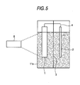
- a sealed cell 11a for electrolysis such as that shown in Fig. 5 was used as an apparatus for conducting an experiment concerning hydrogen generation by a treatment of hydrogen sulfide with a photocatalyst.
- the anode side and the cathode side had been separated from each other by a cation-exchange membrane 3.
- the anode side was filled with the 0.09 mol/L hydrogen sulfide solution produced in the hydrogen sulfide dissolution step, and a photocatalyst electrode 1 was immersed therein.
- the cathode side was filled with 0.10 mol/L sulfuric acid solution and a metal electrode 2 was immersed therein.
- Numeral 8 denotes a xenon lamp for light irradiation and 4 denotes a lead wire which electrically connects the photocatalyst electrode 1 to the metal electrode 2.
- the photocatalyst electrode 1 was produced by fixing cadmium sulfide to a titanium plate by the method disclosed in JP-A-2003-181297 . This electrode was formed in a size of 100 mm ⁇ 100 mm in terms of electrode area. On the other hand, an electrode obtained by coating a titanium net with platinum was used as the metal electrode 2. This electrode had a size of 80 mm ⁇ 120 mm.
- a copper wire was used as the lead wire 4 to electrically connect the photocatalyst electrode 1 to the metal electrode 2.
- the vessel part of the cell 11a for electrolysis was produced using an acrylic resin.
- the photocatalyst electrode 1 vessel and the metal electrode 2 vessel each had a capacity of 200 mL.
- the apparatus having the constitution explained above was used and the photocatalyst electrode 1 was irradiated with xenon light emitted from the xenon lamp. As a result, the hydrogen generation amount increased almost in proportion to the irradiation time. At 10 minutes after initiation of the irradiation, a measurement of the amount of hydrogen generated was initiated.
- the amount of hydrogen generated in the period from the measurement initiation to 1 hour thereafter was 10.7 mL.
- the use of the xenon lamp 8 as a light source was intended to enable the experiment to proceed quantitatively. It is a matter of course that sunlight is practically usable as a light source.
- a second-embodiment apparatus was used for conducting an experiment concerning hydrogen generation by a treatment of hydrogen sulfide with a photocatalyst.
- this apparatus comprised: a cell 11 for electrolysis, as a first liquid tank, which contained a raw liquid prepared by dissolving hydrogen sulfide in an aqueous sodium hydroxide solution so as to result in an HS - concentration of 0.1 M and an OH - concentration of 1 M; and a photoelectrochemical cell 34, as a second liquid tank, which had been disposed so as to be immersed in the cell 11.
- This photoelectrochemical cell 34 had partition materials, one of which comprised: a titanium plate as an electrically conductive base 33; cadmium sulfide fixed as a photocatalyst 31 to the outer side of the titanium plate by the method disclosed in JP-A-2003-181297 to thereby form a photocatalyst electrode 1 having an electrode size of 100 mm ⁇ 100 mm; and platinum, as a metallic layer 32, deposited on the inner side, i.e., the side opposite to the photocatalyst layer, of the titanium base by electroplating to form a metal electrode 2.
- the other of the partition materials, which was disposed on the opposite side, was constituted of a cation-exchange membrane 3.
- the photoelectrochemical cell 34 was constituted as a sealed cell.
- An acrylic resin pipe for supplying/circulating sulfuric acid having a concentration of 0.5 M as an acidic solution was attached to an upper part of the cell 34.
- the cell 11 for electrolysis as a first liquid tank, was constituted of a transparent acrylic resin material.
- the cell 11 for electrolysis was irradiated from the outside with a light using a xenon lamp for light irradiation (not shown) so that the photocatalyst layer 31 had a light irradiation area of 15.9 cm 2 and a light irradiation intensity of 15.1 W.
- the cell 11 for electrolysis had a capacity of 1,750 mL and the photoelectrochemical cell 34 had a capacity of 175 mL.
- the apparatus having the constitution explained about was used and the photocatalyst layer 31 was irradiated with xenon light emitted from the xenon lamp.
- the hydrogen generation amount increased almost in proportion to the irradiation time as shown in Fig. 7.
- a measurement of the amount of hydrogen generated was initiated.
- the amount of hydrogen generated in the period from the measurement initiation to 6 hours thereafter was 53.1 mL.
- the value of photo current between the photocatalyst (CdS) layer 31 (photocatalyst electrode 1) and the metallic (Pt) layer 32 (metal electrode 2) during the photocatalytic reaction (light irradiation) was almost constant at 23 mA.
- the method of treating hydrogen sulfide, method of producing hydrogen, and photocatalytic-reaction apparatus of the invention have exceedingly hopeful applications in chemical industries such as the step of ammonia or methanol production which necessitates hydrogen and the sulfuric acid or insecticide production industry where sulfur is necessary and in the field of chemical industry in which natural gas, various industrial gases, and petroleum are produced or treated and hydrogen sulfide or the like generated in a desulfurization or another step is treated.
Landscapes
- Chemical & Material Sciences (AREA)
- Engineering & Computer Science (AREA)
- Organic Chemistry (AREA)
- Inorganic Chemistry (AREA)
- Chemical Kinetics & Catalysis (AREA)
- Health & Medical Sciences (AREA)
- Environmental & Geological Engineering (AREA)
- Analytical Chemistry (AREA)
- Biomedical Technology (AREA)
- General Chemical & Material Sciences (AREA)
- Oil, Petroleum & Natural Gas (AREA)
- Materials Engineering (AREA)
- General Health & Medical Sciences (AREA)
- Combustion & Propulsion (AREA)
- Electrochemistry (AREA)
- Metallurgy (AREA)
- Catalysts (AREA)
- Electrolytic Production Of Non-Metals, Compounds, Apparatuses Therefor (AREA)
Applications Claiming Priority (2)
| Application Number | Priority Date | Filing Date | Title |
|---|---|---|---|
| JP2005101849 | 2005-03-31 | ||
| PCT/JP2006/306570 WO2006106784A1 (fr) | 2005-03-31 | 2006-03-29 | Procede de traitement de sulfure d’hydrogene, procede de production d’hydrogene et reacteur de photocatalyseur |
Publications (2)
| Publication Number | Publication Date |
|---|---|
| EP1867390A1 true EP1867390A1 (fr) | 2007-12-19 |
| EP1867390A4 EP1867390A4 (fr) | 2010-11-24 |
Family
ID=37073342
Family Applications (1)
| Application Number | Title | Priority Date | Filing Date |
|---|---|---|---|
| EP06730518A Withdrawn EP1867390A4 (fr) | 2005-03-31 | 2006-03-29 | Procede de traitement de sulfure d hydrogene, procede de production d hydrogene et reacteur de photocatalyseur |
Country Status (5)
| Country | Link |
|---|---|
| US (1) | US7985397B2 (fr) |
| EP (1) | EP1867390A4 (fr) |
| KR (1) | KR20070118668A (fr) |
| CN (1) | CN101180127A (fr) |
| WO (1) | WO2006106784A1 (fr) |
Families Citing this family (5)
| Publication number | Priority date | Publication date | Assignee | Title |
|---|---|---|---|---|
| CN102369312B (zh) * | 2009-04-15 | 2014-11-05 | 松下电器产业株式会社 | 氢气生成装置 |
| IT1403892B1 (it) | 2010-12-29 | 2013-11-08 | Eni Spa | Cella fotoelettrolitica tandem per la foto-ossidazione di solfuri con produzione di idrogeno |
| US20130092549A1 (en) * | 2011-04-01 | 2013-04-18 | California Institute Of Technology | Proton exchange membrane electrolysis using water vapor as a feedstock |
| CN102329006B (zh) * | 2011-07-28 | 2015-05-20 | 西安交通大学 | 同时产电、产氢及污水处理的微生物光电化学系统 |
| CN106587280B (zh) * | 2016-11-11 | 2020-02-07 | 西安交通大学 | 协同处理有机废液和重金属废液并产电的光电化学方法和装置 |
Citations (1)
| Publication number | Priority date | Publication date | Assignee | Title |
|---|---|---|---|---|
| US3925212A (en) * | 1974-01-02 | 1975-12-09 | Dimiter I Tchernev | Device for solar energy conversion by photo-electrolytic decomposition of water |
Family Cites Families (12)
| Publication number | Priority date | Publication date | Assignee | Title |
|---|---|---|---|---|
| US4094751A (en) * | 1976-09-30 | 1978-06-13 | Allied Chemical Corporation | Photochemical diodes |
| CH644471A5 (fr) * | 1981-02-02 | 1984-07-31 | Michael Graetzel | Produit destine a etre utilise comme photocatalyseur, procede de preparation de ce produit et utilisation de ce produit. |
| NL8200897A (nl) | 1982-03-04 | 1983-10-03 | Tno | Foto-elektrochemische cel, werkwijze voor de foto-elektrolyse van water, alsmede werkwijze voor het opslaan respectievelijk benutten van de daarbij gevormde waterstof. |
| US4526774A (en) * | 1984-04-27 | 1985-07-02 | Standard Oil Company (Indiana) | Separation of hydrogen sulfide from gaseous and non-aqueous liquid streams |
| US5147620A (en) * | 1989-06-08 | 1992-09-15 | Linko Enterprises, Inc. | Process for the purification of gaseous streams |
| JP3602268B2 (ja) * | 1996-07-15 | 2004-12-15 | 日揮株式会社 | 天然ガス等に含まれる硫黄化合物の除去方法およびその装置 |
| US5908545A (en) * | 1997-08-19 | 1999-06-01 | Natural Resources Canada | Electrochemical process for decomposing hydrogen sulfide to produce hydrogen and sulfur |
| JP4496444B2 (ja) | 2000-01-06 | 2010-07-07 | 和幸 田路 | 光触媒及びその製造方法並びに該光触媒を用いた硫化水素の分解方法 |
| JP2003181297A (ja) * | 2001-12-19 | 2003-07-02 | Japan Science & Technology Corp | 薄膜状光触媒、その作製方法、およびその薄膜状光触媒を用いた硫化水素の処理方法と水素の製造方法 |
| JP4357801B2 (ja) * | 2002-06-25 | 2009-11-04 | 日鉄鉱業株式会社 | 高活性光触媒およびその製造方法 |
| JP2004256378A (ja) | 2003-02-27 | 2004-09-16 | National Institute Of Advanced Industrial & Technology | 水素及び酸素の製造方法及びその装置 |
| US20060196776A1 (en) * | 2005-03-04 | 2006-09-07 | World Hydrogen, Inc. | Apparatus and method for producing sulfur from hydrogen sulfide |
-
2006
- 2006-03-29 CN CNA2006800174647A patent/CN101180127A/zh active Pending
- 2006-03-29 US US11/910,026 patent/US7985397B2/en active Active
- 2006-03-29 KR KR1020077024921A patent/KR20070118668A/ko not_active Application Discontinuation
- 2006-03-29 WO PCT/JP2006/306570 patent/WO2006106784A1/fr active Application Filing
- 2006-03-29 EP EP06730518A patent/EP1867390A4/fr not_active Withdrawn
Patent Citations (1)
| Publication number | Priority date | Publication date | Assignee | Title |
|---|---|---|---|---|
| US3925212A (en) * | 1974-01-02 | 1975-12-09 | Dimiter I Tchernev | Device for solar energy conversion by photo-electrolytic decomposition of water |
Non-Patent Citations (2)
| Title |
|---|
| DATABASE WPI Week 198343 Thomson Scientific, London, GB; AN 1983-799057 XP002605310 -& NL 8 200 897 A (NEDERLAND ORG TNO) 3 October 1983 (1983-10-03) * |
| See also references of WO2006106784A1 * |
Also Published As
| Publication number | Publication date |
|---|---|
| US20080245655A1 (en) | 2008-10-09 |
| EP1867390A4 (fr) | 2010-11-24 |
| WO2006106784A1 (fr) | 2006-10-12 |
| CN101180127A (zh) | 2008-05-14 |
| KR20070118668A (ko) | 2007-12-17 |
| US7985397B2 (en) | 2011-07-26 |
Similar Documents
| Publication | Publication Date | Title |
|---|---|---|
| CN102482789B (zh) | 气体生成装置以及气体生成方法 | |
| EP1913965B1 (fr) | Appareil photolytique pour oxygéner et éliminer oxyde de carbon | |
| Xie et al. | Degradation of bisphenol A in aqueous solution by H2O2-assisted photoelectrocatalytic oxidation | |
| Luo et al. | Self-driven photoelectrochemical splitting of H2S for S and H2 recovery and simultaneous electricity generation | |
| EP1454036B1 (fr) | Oxygenateur photolytique a fixation et separation de dioxyde de carbone | |
| US7985397B2 (en) | Method of treating hydrogen sulfide, method of producing hydrogen, and photocatalytic-reaction apparatus | |
| CN105236628B (zh) | 光电协同催化降解污水装置 | |
| Mei et al. | Efficient SO2 removal and highly synergistic H2O2 production based on a novel dual-function photoelectrocatalytic system | |
| CN104630816B (zh) | 基于太阳能和海水电池协同驱动的光电降解有机污染物制氢的装置及工艺 | |
| JPH029850B2 (fr) | ||
| CN109160575A (zh) | 一种自偏压双光电极体系及应用 | |
| CN105293644B (zh) | 光电化学电解设备及用于该光电化学电解设备的电极板 | |
| EP1609886A1 (fr) | Procédé de production d'hydrogène | |
| EP3990395B1 (fr) | Systeme photo-electrique | |
| JP2010194472A (ja) | バイオマス・有機・無機化合物または廃棄物・廃液を高効率で光分解浄化し同時に電力を発生するバイオ光化学電池と、該バイオ光化学電池を用いて該化合物や液体を光分解浄化すると同時に電力を発生させる方法 | |
| Chowdhury | Solar and Visible Light Driven Photocatalysis for Sacrificial Hydrogen Generation and Water Detoxification with Chemically Modified Ti0 2 | |
| JP5194284B2 (ja) | 硫化水素の処理方法、水素の製造方法および光触媒反応装置 | |
| US7704914B2 (en) | Photocatalyst and process for producing the same | |
| JP2006182615A (ja) | 窒素含有化合物の光分解方法 | |
| CN206476851U (zh) | 一种含金电镀废水的资源化回收处理装置 | |
| JP2010090466A (ja) | 硫化水素含有液の処理方法及び処理装置。 | |
| KR101127874B1 (ko) | 해수 전해액을 이용한 광감응 소재의 제조방법 및 그 광감응 소재와 이를 활용한 광전기화학적 수소제조장치 및 6가 크롬 환원장치 | |
| JP3920737B2 (ja) | 硝酸性窒素の処理方法および処理装置 | |
| JP2020126712A (ja) | 水電池、水電池用活性化水の製造方法、水電池の連続使用方法 | |
| Guo et al. | Hydrogen generation from the atmospheric water |
Legal Events
| Date | Code | Title | Description |
|---|---|---|---|
| PUAI | Public reference made under article 153(3) epc to a published international application that has entered the european phase |
Free format text: ORIGINAL CODE: 0009012 |
|
| 17P | Request for examination filed |
Effective date: 20070927 |
|
| AK | Designated contracting states |
Kind code of ref document: A1 Designated state(s): AT BE BG CH CY CZ DE DK EE ES FI FR GB GR HU IE IS IT LI LT LU LV MC NL PL PT RO SE SI SK TR |
|
| DAX | Request for extension of the european patent (deleted) | ||
| A4 | Supplementary search report drawn up and despatched |
Effective date: 20101027 |
|
| RIC1 | Information provided on ipc code assigned before grant |
Ipc: C25B 1/00 20060101ALI20101019BHEP Ipc: B01J 35/02 20060101AFI20061018BHEP Ipc: B01D 53/86 20060101ALI20101019BHEP Ipc: C01B 3/04 20060101ALI20101019BHEP |
|
| RAP1 | Party data changed (applicant data changed or rights of an application transferred) |
Owner name: NITTETSU MINING CO., LTD. Owner name: TOHOKU UNIVERSITY |
|
| STAA | Information on the status of an ep patent application or granted ep patent |
Free format text: STATUS: THE APPLICATION IS DEEMED TO BE WITHDRAWN |
|
| 18D | Application deemed to be withdrawn |
Effective date: 20110526 |